EP3814918B1 - Asynchrone kommunikation - Google Patents
Asynchrone kommunikation Download PDFInfo
- Publication number
- EP3814918B1 EP3814918B1 EP19733774.4A EP19733774A EP3814918B1 EP 3814918 B1 EP3814918 B1 EP 3814918B1 EP 19733774 A EP19733774 A EP 19733774A EP 3814918 B1 EP3814918 B1 EP 3814918B1
- Authority
- EP
- European Patent Office
- Prior art keywords
- mutex
- status
- channel
- reverse
- flag
- Prior art date
- Legal status (The legal status is an assumption and is not a legal conclusion. Google has not performed a legal analysis and makes no representation as to the accuracy of the status listed.)
- Active
Links
Images




Classifications
-
- G—PHYSICS
- G06—COMPUTING OR CALCULATING; COUNTING
- G06F—ELECTRIC DIGITAL DATA PROCESSING
- G06F13/00—Interconnection of, or transfer of information or other signals between, memories, input/output devices or central processing units
- G06F13/38—Information transfer, e.g. on bus
- G06F13/40—Bus structure
- G06F13/4004—Coupling between buses
- G06F13/4027—Coupling between buses using bus bridges
- G06F13/405—Coupling between buses using bus bridges where the bridge performs a synchronising function
- G06F13/4054—Coupling between buses using bus bridges where the bridge performs a synchronising function where the function is bus cycle extension, e.g. to meet the timing requirements of the target bus
-
- G—PHYSICS
- G06—COMPUTING OR CALCULATING; COUNTING
- G06F—ELECTRIC DIGITAL DATA PROCESSING
- G06F13/00—Interconnection of, or transfer of information or other signals between, memories, input/output devices or central processing units
- G06F13/38—Information transfer, e.g. on bus
- G06F13/40—Bus structure
- G06F13/4004—Coupling between buses
- G06F13/4027—Coupling between buses using bus bridges
- G06F13/4031—Coupling between buses using bus bridges with arbitration
-
- G—PHYSICS
- G06—COMPUTING OR CALCULATING; COUNTING
- G06F—ELECTRIC DIGITAL DATA PROCESSING
- G06F13/00—Interconnection of, or transfer of information or other signals between, memories, input/output devices or central processing units
- G06F13/38—Information transfer, e.g. on bus
- G06F13/42—Bus transfer protocol, e.g. handshake; Synchronisation
- G06F13/4282—Bus transfer protocol, e.g. handshake; Synchronisation on a serial bus, e.g. I2C bus, SPI bus
- G06F13/4286—Bus transfer protocol, e.g. handshake; Synchronisation on a serial bus, e.g. I2C bus, SPI bus using a handshaking protocol, e.g. RS232C link
Definitions
- the present invention relates to asynchronous communication, in particular to the asynchronous transfer of data across clock and/or power domain crossings in an electronic device.
- Modern electronic devices for example radio transceiver devices arranged to carry out wireless communication such as Bluetooth ® or Wi-Fi ® communication, may have two or more different power and/or clock domains that may be required, at least sporadically, to communicate with each other.
- a clock domain refers to circuitry that is driven by a particular clock signal while a power domain refers to circuitry that driven by the same supply voltage.
- a central processor may run in a first clock domain at a relatively high frequency while one or more peripherals may run in a second clock domain at a relatively low frequency.
- an asynchronous crossing of signals across power and/or clock domain boundaries is required to pass from one domain to another.
- AHB Advanced High Performance Bus
- SoC system-on-chip
- An asynchronous AHB-AHB bridge may typically be used to facilitate the transfer of data from one AHB to the other, where the originating AHB is connected as a slave component to the bridge, (referred to herein as a 'slave') and the destination AHB has the same bridge connected as an AHB master component (referred to herein as a 'master').
- One type of handshaking procedure is a two-phase or two-step handshaking procedure.
- the initiator begins by toggling the state of its request signal (i.e. flipping the signal either from low to high or from high to low, changing its previous state to the opposite state as appropriate).
- the receiver then acknowledges this request by toggling the state of its acknowledgement signal to complete the handshake.
- this two-phase process is unsuitable for use when either side - i.e. the initiator or receiver - may reset (or even power off, such that isolation clamp values define the signal state observed by the other side) during the handshake as this reset can, in some circumstances, be seen as the completion of the handshake.
- the acknowledgement signal may change to low due to the reset rather than as an actual acknowledgement of the initiator's request.
- desynchronisation This issue of undesired state changes due to reset and/or losing power in a handshake is known as desynchronisation.
- US 5 692 137 A appears to disclose an interface between two buses in different clock domains.
- the interface includes a master buffer which is used for both master writes and slave reads.
- a control logic unit for each bus receives signals from a buffer manager which straddles the clock domains to gate latch pulses to the master buffer.
- US 2002/052999 A1 discloses a multiple transaction advanced high performance bus AHB system comprising two AHB buses capable of simultaneous activity. The two buses are separated by and synchronised with an AHB-to-HTB bus bridge.
- the present invention provides a method of transferring data from a first bus to a second bus across an asynchronous interface between said first and second buses according to claim 1.
- This first aspect of the invention extends to an asynchronous bridge arranged to transfer data from a first bus to a second bus across an asynchronous interface between said first and second buses according to claim 11.
- the method further comprises:
- both sides of the asynchronous bridge are reset or lose power thereby giving rise to a desynchronisation, automatically performing a resynchronisation.
- said resynchronisation comprises said forward channel initiator toggling the control request flag or said reverse channel initiator toggling the reverse control request flag and the corresponding forward channel terminator toggling the control acknowledgement flag or the reverse channel terminator toggling the reverse control acknowledgment flag in response; the status mutex and/or the reverse status mutex thereby becoming locked.
- each toggle of a data-request signal indicates a request for the handshake and each toggle of a data-acknowledge signal indicates the completion of the handshake.
- control request flag and/or control acknowledgement flags change value
- one of the bus slave module and the bus master module which has detected said change in value changing all flags to corresponding reset values and the other of the bus slave module and the bus master module, when its reset completes before the other side can return to the reset value, waiting until all handshake flags across the boundary are their reset values again.
- an improved electronic device and method of operating the same in which an improved four-phase handshake is used to determine whether the slave and master modules have been desynchronised before completing the transfer of data across the asynchronous interface.
- the Applicant has appreciated that such an arrangement may result in a handshake protocol with the same number of phases as a conventional four-phase handshake when no status synchronisation is available (e.g. when one or both sides are not powered up and ready for use) - namely two steps dedicated to performing a status handshake and then two steps dedicated to performing a data transfer handshake, but then only requires the two-phase data transfer handshake for subsequent data transfers until either or both of the master and slave modules reset (and the status 'lock' is lost due to desynchronisation).
- an initial four-phase handshake is carried out for the first transaction, and the described handshake is used in order to monitor that neither the slave module nor the master module has reset and caused a desynchronisation (because if one or both of these modules resets, the semaphore/mutex has to reset i.e. loses its lock), which provides the robustness associated with some known four-phase handshake procedures as outlined above.
- subsequent transactions may advantageously occur at the speeds typically associated with two-phase handshake procedures, because the semaphore/ mutex is used to ensure that the synchronisation status established earlier in the initial four phase handshake procedure can still be trusted, removing the need to check the synchronisation status for every data transaction.
- the term 'desynchronisation' and derivatives thereof as used herein mean that the initiator and terminator modules, which are typically asynchronous from the point of view of their clock domains but communicate across the asynchronous interface through use of handshake arrangements to implement a mutex, become 'out of step' with one another, for example where the internal states of each module conflict with one another. This misalignment of states is thus more than merely a consequence of how the modules are clocked.
- the reverse data channel of the described bridge may only be used when the forward data channel is used to pass a request from a component with a bus master in one power and/or clock domain to a component with bus slave in another.
- the status part of the handshake as described may provide the same information for both the forward and reverse mutexes.
- the reverse channel can therefore use the status lock of the forward channel, as any desynchronisation happens for both channels at the same time.
- the described handshake may be seen as a composite of a status handshake or status mutex and a data handshake or data mutex.
- Embodiments may seek to mitigate these by any one of more of the following: delaying detected phase changes for the data mutex by one cycle, holding data after capture for enough cycles to detect whether captured data is valid (reducing throughput) or providing an early warning signal to the bridge component that the other side is bound to reset soon and any changes from the data mutex should be ignored to prevent a data hazard (best performance).
- Any unexpected reset of the receiving side may, in some arrangements, be detected and recovered from using only information from the 'control channels', where one channel, handled by the status mutex, carries status information (that both the slave module and the master module are ready to carry out transactions) and the second channel, handled by the semaphore or data mutex (e.g. the semaphore initiator and terminator pair), provides a transaction-specific handshake to guard data crossing the asynchronous interface, i.e. a power and/or clock boundary.
- the semaphore or data mutex e.g. the semaphore initiator and terminator pair
- an asynchronous bridge in accordance with embodiments of the present invention may support multiple independent power domains and resets, unlike conventional two-phase handshake procedures known in the art per se. Furthermore, because the power and reset status may be determined locally by such a bridge, there may advantageously be no need for a global power and clock manager.
- a mutex is typically an arrangement that provides for mutual exclusion concurrency control (i.e. control that ensures correct results for concurrent operations).
- the status mutex comprises a control request flag, a control acknowledgement flag, and a mutex lock flag, wherein the status mutex is arranged such that:
- the status mutex may be considered the implementation part of the described handshake which ensures both sides are ready for use.
- the semaphore referred to herein may have a value of 1 and thus may be considered to be a mutex or a data mutex.
- References herein to a semaphore initiator and a semaphore terminator may therefore be understood accordingly as references to a mutex initiator and a mutex terminator respectively or to a data mutex initiator and a data mutex terminator.
- the master module is arranged to determine that a desynchronisation event has occurred when the control request flag and the mutex lock flag are raised while the status mutex is not locked.
- the slave module may be arranged to determine that a desynchronisation event has not yet been detected by the master module, which is indicated by the control acknowledgement flag being raised even though the slave module has not raised the control request flag since the last reset of the slave module.
- the embodiments of the present invention described hereinabove provide for communication of data from the first bus to the second bus, such that the semaphore/data mutex initiator of the slave module and the semaphore/data mutex terminator of the master module form a transaction channel.
- the slave module comprises a return (reverse-channel) data mutex/semaphore terminator and the master module comprises a return data mutex/semaphore initiator, wherein the asynchronous bridge is further arranged such that:
- the slave module raises a valid flag when it has data to send to the master module, wherein the valid flag is cleared when the slave module is reset.
- the valid flag is cleared when either of the slave module and the master module is reset.
- the master module raises a further valid flag when it has data to send to the slave module, wherein the further valid flag is cleared when the master module is reset.
- the further valid flag is cleared when either of the slave module and the master module is reset.
- an asynchronous bridge operating in accordance with embodiments of the claimed invention may overcome issues with an unscheduled power off (or reset) occurring which causes erroneous behaviour in the master module and/or the slave module.
- power offs and resets might be known about in advance, i.e. they are scheduled, albeit not always a long time in advance - i.e. such a reset may be scheduled for a certain time or may be scheduled imminently in response to a particular event.
- the slave module is arranged to send a warning signal directly to the master module when the slave module has a power off event or reset event scheduled, wherein the master module is arranged to abort any current transaction of data across the asynchronous interface upon receiving said warning signal.
- the master module is arranged to send a warning signal directly to the slave module when the master module has a power off event or reset event scheduled, wherein the slave module is arranged to abort any current transaction of data across the asynchronous interface upon receiving said warning signal.
- the slave module and/or the master module may be warned in advance of an upcoming power off of the other module and abort any current transactions which may prevent errors.
- Fig. 1 is a schematic diagram of an asynchronous bridge 2 in accordance with an embodiment of the present invention.
- the asynchronous bridge 2 comprises a slave module 4 and a master module 6, which are separated by an asynchronous boundary 7.
- This asynchronous boundary 7 is a result of the slave module 4 and master module 6 being located within different power and clock domains. It will of course be appreciated that the slave module 4 and master module 6 could be in different clock domains but in the same power domain or vice versa, however in this exemplary embodiment, the modules 4, 6 are in both different clock and power domains.
- the slave module 4 comprises: a status mutex initiator 8; an AHB receiver 10; a data mutex initiator 12; and a data mutex terminator 14.
- the AHB receiver 10 comprises: a finite state machine (FSM) 16; and two multi-flip-flop synchronisers 18, 20.
- FSM finite state machine
- the AHB receiver 10 is known as a 'receiver', because it receives data from a first bus 11.
- the master module 6 comprises: a status mutex terminator 22; an AHB transmitter 24; a data mutex terminator 26; and a data mutex initiator 28.
- the AHB transmitter 24 comprises: an FSM 30; and two multi-flip-flop synchronisers 32, 34.
- the AHB transmitter 24 is known as a transmitter, because it transmits data to a second bus 13.
- the status mutex initiator 8 of the slave module 4 and the status mutex terminator 22 of the master module 6 together form a 'status mutex', i.e. a mutex that monitors the status of the connection between the slave module 4 and the master module 6 across the asynchronous interface 7 as will be described in further detail below.
- the data mutex initiator 12 of the slave module 4 and the data mutex terminator 26 of the master module 6 together form a transaction channel between the slave module 4 and the master module 6, while the data mutex terminator 14 of the slave module 4 and the data mutex initiator 28 of the master module 6 together form a return channel between the slave module 4 and the master module 6.
- Fig. 2 is a flowchart showing the handshaking and transfer procedure carried out by the asynchronous bridge 2 when the slave module 4 receives data via the first bus 11 that needs to be transferred to the second bus 13 across the asynchronous interface 7 (i.e. over the clock- and power-domain boundary).
- the procedure is initialised at step 100, and the slave module 4 determines whether the status mutex is currently locked at step 102. If the status mutex is not currently locked, the slave module determines whether the control acknowledgement flag 38 is raised or not. If the control acknowledgement flag 38 is not raised, the status mutex initiator 8 raises a control request flag 36 at step 106, which is detected by the status mutex terminator 22. However, if at step 104 the control acknowledgement flag 38 is raised despite the control request flag 36 not yet being raised, this indicates a desynchronisation 101 has occurred and that the asynchronous bridge 2 waits at step 103 until the desynchronisation 101 has been detected by both the slave module 4 and the master module 6 before returning to step 102 and checking whether the status mutex is locked.
- the master module 6 determines, at step 108, whether the locked flag 40 is raised. If the locked flag 40 is not currently raised, the status mutex terminator 22 then raises a control acknowledgement flag 38 in response to the control request flag 36 at step 110, which is detected by the status mutex initiator 8. If, however, at step 108 the locked flag 40 is raised before the control acknowledgement flag 38 has been, this indicates a desynchronisation 101. As outlined above, the asynchronous bridge 2 waits at step 103 until the desynchronisation 101 has been detected by both the slave module 4 and the master module 6 before returning to step 102 and checking whether the status mutex is locked.
- the status mutex initiator 8 raises a mutex locked flag 40 and the mutex formed by the status mutex initiator 8 and the status mutex terminator 22 is locked.
- This request-and-acknowledgement procedure essentially forms a first two-phase handshake.
- the procedure carried out using the mutex assures that the slave module 4 and the master module 6 are synchronised to (i.e. 'in step' with) each other and monitors this for desynchronisation throughout data transactions, as outlined below.
- the AHB receiver 10 may transfer data received via the first bus 11 to the master module 6 across the asynchronous interface 7.
- the data mutex initiator 12 of the transaction channel i.e. the data mutex initiator 12 of the slave module 4) toggles the value of a data request flag 42 at step 114. It will be appreciated that by toggling the value of the data request flag 42, this means changing the value to the logical negation of its current value, i.e. if it is currently a digital '1', it is changed to a digital '0' and vice versa.
- the AHB receiver 10 then transfers the data 43 across the asynchronous interface 7 through the multi-flip-flop synchroniser 18 and raises a valid flag 45.
- the data mutex terminator 26 of the transaction channel detects this change in the data request flag 42 and determines from the valid flag 45 that valid data 43 is present and ready to be transferred across to the second bus 13.
- the AHB transmitter 24 within the master module 6 receives the data 43 from the AHB receiver 10 (i.e. from the slave module 4) via the multi-flip-flop synchroniser 32.
- the data mutex terminator 26 then toggles the value of a data acknowledgement flag 44 so as to match the value of the data request flag 42, acknowledging the safe receipt of the data 43 at step 118.
- step 120 It is determined at step 120 whether more data is to be transferred across the asynchronous interface 7. If further data is to be transferred from the first bus 11 to the second bus 13, the procedure returns to step 102 and the process is repeated as outlined above. Otherwise, the procedure ends at step 122.
- the AHB transmitter 24 within the master module 6 may similarly transfer data to the AHB receiver 10 across the asynchronous interface 7 using the return channel, i.e. using the data mutex initiator 28 of the master module 6 and the data mutex terminator 14 of the slave module 4.
- the data mutex initiator 28 of the return channel toggles the value of a data request flag 46.
- the AHB transmitter 24 then transfers the data 47 across the asynchronous interface 7 through the multi-flip-flop synchroniser 34 and raises a valid flag 49.
- the data mutex terminator 14 of the return channel detects this change in the data request flag 46 and determines from the valid flag 49 that valid data 47 is present and ready to be transferred across to the first bus 11.
- the AHB receiver 10 within the slave module 4 receives the data 47 from the AHB transmitter 24 (i.e. from the master module 6) via the multi-flip-flop synchroniser 20.
- the data mutex terminator 14 then toggles the value of a data acknowledgement flag 48 so as to match the value of the data request flag 46, acknowledging the safe receipt of the data 47.
- Fig. 3 is a timing diagram showing the status mutex locking operation used in the asynchronous bridge of Fig. 1 .
- the slave module 4 is held in reset by its asynchronous reset signal arst_slave being held at logic high.
- the asynchronous reset signal arst_slave of the slave module 4 is set to logic low, allowing the slave module 4 out of reset.
- the slave module 4 starts the process of locking the status mutex by setting an internal signal getLock_slave high, and also initiates a clock signal ck_slave which clocks components within the slave module 4, including the multi-flip-flop synchronisers 18, 20 that are used for transferring data from the first bus 11.
- the status mutex initiator 8 raises a control request flag 36 as outlined previously above. In this case, no desynchronisation takes place and the status mutex terminator 22 determines that it should acknowledge the request. Before it does so, a clock signal ck_master used by components of the master is initialised at t 4 . The master module 6 subsequently determines that no desynchronisation has taken place and so can set an internal signal hasLock_master to logic high at t 5 , indicating that the master module 6 considers the status mutex to be locked (pending the slave module 4 doing the same).
- the status mutex terminator 22 subsequently raises the control acknowledgement flag 38 at t 6 , which is detected by the status mutex initiator 8.
- the status mutex initiator 8 sets an internal signal hasLock_slave to logic high at t 7 , indicating that the slave module 4 considers the status mutex to be locked.
- the status mutex initiator 8 then sets the locked flag 40 to logic high at t 8 , indicating that the status mutex is locked.
- Fig. 4 is a timing diagram showing the desynchronisation operation of the asynchronous bridge of Fig. 1 when the slave module resets before the master module is provided with its clock.
- the status mutex initiator 8 will keep the locked flag 40 low and pull the control request flag 36 high, but only if the control acknowledgement flag 38 is low, as outlined previously.
- the slave module 4 After an initial idle period 50, at time t 9 , the slave module 4 is reset by pulsing its asynchronous reset signal arst_slave to logic high. The reset of the slave module 50 also pulls the control request flag 36 and the locked flag 40 to logic low. Once the asynchronous reset signal arst_slave of the slave module 4 returns to logic low, the slave module 4 is allowed out of reset and the slave module enters a 'bootstrapping' period 52, during which time the slave module 4 attempts to start locking the status mutex as outlined above with reference to Fig. 3 , setting the internal signal getLock_slave high and initiating the clock signal ck_slave as outlined above.
- the control acknowledgement flag 38 is already high when attempting to lock the status mutex, this indicates that the master module 6 has not yet detected the desynchronisation.
- the slave module 4 then enters a wait period 54 until the master module 6 detects that the desynchronisation has occurred (i.e. the master module 6 determines that the slave module 4 has been reset).
- the master module 6 detects the loss of the lock of the status mutex at time t 11 , and sets its internal signal hasLock_master to logic low and pulses a further internal signal lostLock_master, that indicates the status mutex having lost its lock, to logic high.
- the status mutex enters a locking period 56 at time t 12 in which the status mutex initiator 8 and terminator 22 undergo the locking procedure outlined above such that the status mutex is locked.
- the status mutex then enters a locked state 58 at time t 13 thereafter until the lock is lost at a later time (not shown).
- Fig. 5 is a timing diagram showing the operation of the asynchronous bridge of Fig. 1 when the slave module 4 breaks the status mutex lock.
- the slave module 4 is reset by pulling its asynchronous reset signal arst_slave to logic high.
- the status mutex control signals managed by the status mutex initiator 8 i.e. the control request flag 36 and the locked flag 40 are pulled to logic low.
- the master module 6 detects the loss of the lock at t 15 and sets its internal signal hasLock_master to logic low and pulses lostLock_master to logic high.
- the status mutex terminator 22 then sets the control acknowledgement flag 38 to logic low at t 16 .
- Fig. 6 is a timing diagram showing the operation of the asynchronous bridge of Fig. 1 when the master module 6 breaks the status mutex lock.
- the master module 6 is reset by pulling its asynchronous reset signal arst_master to logic high.
- the status mutex control signal managed by the status mutex terminator 22, i.e. the control acknowledgement flag 38 is pulled to logic low.
- the slave module 4 detects the loss of the lock at t 18 and sets an internal signal hasLock_slave to logic low and pulses a signal lostLock_slave indicating that the mutex lock has been lost to logic high.
- the status mutex initiator 8 then sets the control request flag 36 and the locked flag 40 to logic low at t 19 .
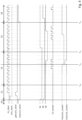
- Fig. 7 is a timing diagram showing the operation of the data mutex used in the asynchronous bridge of Fig. 1 .
- the master module 6 is released from reset by setting its asynchronous reset signal arst_master to logic low.
- the slave module 4 is also released from reset by setting its asynchronous reset signal arst_slave to logic low, and the data mutex initiator 12 pulses a signal newTrans(in) to logic high, which indicates to the FSM 16 of the slave module 4 that a data transaction event is to occur.
- the data mutex initiator also begins transferring the data 43 at this time t 21 .
- the data mutex initiator 12 toggles the value of the data request flag 42 at t 22 and the AHB receiver 10 then transfers the data 43 across the asynchronous interface 7 through the multi-flip-flop synchroniser 18. For correct operation, the data 43 must remain stable until it is received by the master module 6.
- the data mutex terminator 26 After the data mutex terminator 26 has synchronised the toggling of the data request flag 42, the data mutex terminator 26 pulses a signal newTrans(out) to logic high at t 23 , which indicates to the FSM 30 of the master module 6 that a transaction is occurring. After sampling the data 43, the FSM 30 of the master module 6 sets a further signal acceptTrans(in) to logic high at t 24 , which indicates that the transaction has been successfully accepted by the master module 6. The master module 6 then toggles the data acknowledgement flag 44 to match the value of the data request flag 42 at t 25 .
- the slave module 4 After detecting the toggling of the data request flag 42, at t 26 the slave module 4 pulses a further signal acceptTrans(out) to logic high, which indicates that the acknowledgement has been successfully accepted by the slave module 4, and sets the waiting signal to logic low at t 27 , concluding the transaction.
- embodiments of the present invention provide an improved electronic device including an oscillator circuit and an improved method for operating the same in which a four-phase handshake is used for an initial transaction in which a mutex is used to monitor the synchronisation status of the bridge, but that two-phase transactions are used for further transactions so long as the mutex remains locked.
- An asynchronous bridge in accordance with embodiments of the present invention may therefore be more robust against desynchronisation events than a conventional two-phase handshake while carrying out transactions faster than a conventional four-phase handshake. It will be appreciated by those skilled in the art that the embodiments described above are merely exemplary and are not limiting on the scope of the invention.
Landscapes
- Engineering & Computer Science (AREA)
- Theoretical Computer Science (AREA)
- General Engineering & Computer Science (AREA)
- Physics & Mathematics (AREA)
- General Physics & Mathematics (AREA)
- Computer Hardware Design (AREA)
- Information Transfer Systems (AREA)
- Power Sources (AREA)
Claims (11)
- Verfahren zum Übertragen von Daten von einem ersten Bus (11) an einen zweiten Bus (13) über eine asynchrone Schnittstelle (7) zwischen dem ersten und zweiten Bus (11, 13) unter Verwendung einer asynchronen Brücke (2), umfassend:ein mit dem ersten Bus (11) verbundenes Bus-Slave-Modul (4), das einen Vorwärtskanalinitiator (8) in einem ersten Leistungs- und/oder Taktbereich umfasst; undein mit dem zweiten Bus (13) verbundenes Bus-Master-Modul (6), das eine Vorwärtskanalabschlussschaltung (22) in einem zweiten Leistungs- und/oder Taktbereich umfasst; wobei der Vorwärtskanalinitiator (8) und die Vorwärtskanalabschlussschaltung (22) in Kommunikation sind, um einen Status-Mutex zum Arbitrieren von Zugriff auf Signale zu bilden, die verwendet werden, um Daten von dem ersten Leistungs- und/oder Taktbereich an den zweiten Leistungs- und/oder Taktbereich zu übertragen, wobei der Status-Mutex ein Steuerungsanforderungsflag (36), ein Steuerungsanerkennungsflag (38) und ein Mutex-Sperrflag (40) umfasst, und wobei der Status-Mutex angeordnet ist, sodass:der Vorwärtskanalinitiator (8) die Steuerungsanforderungsflag (36) nur dann setzt, wenn die Steuerungsanerkennungsflag (38) nicht gesetzt ist;die Vorwärtskanalabschlussschaltung (22) die Steuerungsanerkennungsflag (38) als Reaktion darauf setzt, dass die Steuerungsanforderungsflag (36) nur dann gesetzt wird, wenn die Mutex-Sperrflag (40) nicht gesetzt ist;der Status-Mutex gesperrt ist und der Vorwärtskanalinitiator (8) die Mutex-Sperrflag (40) als Reaktion darauf setzt, dass die Steuerungsanerkennungsflag gesetzt ist;wobei das Verfahren umfasst:wenn der Status-Mutex gesperrt ist (40), Verwenden eines Vorwärtsdatenkanals (43) zum Übertragen von Daten zwischen dem ersten und zweiten Leistungs- und/oder Taktbereich;wenn der Status-Mutex entsperrt ist (40), Umschalten durch den Vorwärtskanalinitiator (8) des Steuerungsanforderungsflags (36) und als Reaktion darauf, Umschalten durch die Vorwärtskanalabschlussschaltung (22) des Steuerungsanerkennungsflags (38); wobei der Status-Mutex dadurch gesperrt wird;wobei, wenn eine der Seiten der asynchronen Brücke (2) zurückgesetzt wird oder Leistung verliert, wodurch eine Desynchronisierung des Status-Mutex auftritt, Erfassen der Desynchronisierung durch den Vorwärtskanalinitiator (8) oder die Vorwärtskanalabschlussschaltung (22) auf der anderen Seite.
- Verfahren nach Anspruch 1, wobei das Bus-Slave-Modul (4) eine Umkehrkanalabschlussschaltung umfasst und das Bus-Master-Modul (6) einen Umkehrkanalinitiator umfasst;
wobei der Umkehrkanalinitiator und die Umkehrkanalabschlussschaltung in Kommunikation sind, um einen Umkehrstatus-Mutex zum Arbitrieren von Zugriff auf Signale zu bilden, die verwendet werden, um Daten von dem zweiten Leistungs- und/oder Taktbereich an den ersten Leistungs- und/oder Taktbereich zu übertragen. - Verfahren nach Anspruch 2, weiter umfassend:wenn der Umkehrstatus-Mutex gesperrt ist, Verwenden eines Umkehrdatenkanals zum Übertragen von Daten zwischen dem zweiten und ersten Leistungs- und/oder Taktbereich;wenn der Umkehrstatus-Mutex entsperrt ist, Umschalten durch den Umkehrkanalinitiator eines Umkehrsteuerungsanforderungsflags und als Reaktion darauf, Umschalten durch die Umkehrkanalabschlussschaltung eines Umkehrsteuerungsanerkennungsflags; wobei der Umkehrstatus-Mutex dadurch gesperrt wird.
- Verfahren nach Anspruch 2 oder 3, weiter umfassend:
wenn eine der Seiten der asynchronen Brücke (2) zurückgesetzt wird oder Leistung verliert, wodurch eine Desynchronisierung des Umkehrstatus-Mutex auftritt, Erfassen der Desynchronisierung durch den Umkehrkanalinitiator oder die Umkehrkanalabschlussschaltung auf der anderen Seite. - Verfahren nach einem vorstehenden Anspruch, weiter umfassend:
wenn beide Seiten der asynchronen Brücke (2) zurückgesetzt werden oder Leistung verlieren, wodurch eine Desynchronisierung auftritt, automatisches Durchführen einer Neusynchronisierung. - Verfahren nach einem vorstehenden Anspruch, weiter umfassend:
wenn der Status-Mutex und/oder der Umkehrstatus-Mutex gesperrt ist/sind und das Steuerungsanforderungsflag oder das Steuerungsanerkennungsflag seinen Wert ändert und/oder ein Umkehrsteuerungsanforderungsflag oder ein Umkehrsteuerungsanerkennungsflag seinen Wert ändert, Durchführen einer Neusynchronisierung. - Verfahren nach Anspruch 5 oder 6, wobei die Neusynchronisierung Umschalten durch den Vorwärtskanalinitiator, des Steuerungsanforderungsflags oder Umschalten durch den Umkehrkanalinitiator, des Umkehrsteuerungsanforderungsflags und als Reaktion, Umschalten durch die entsprechende Vorwärtskanalabschlussschaltung des Steuerungsanerkennungsflags oder Umschalten durch die Umkehrkanalabschlussschaltung des Umkehrsteuerungsanerkennungsflags umfasst; wobei der Status-Mutex und/oder der Umkehrstatus-Mutex dadurch gesperrt wird/werden.
- Verfahren nach einem vorstehenden Anspruch, weiter umfassend:
wenn der Status-Mutex und/oder der Umkehrstatus-Mutex gesperrt ist/sind, wodurch eine Änderung der Steuerungsanforderungs- und der Steuerungsanerkennungsflags und/oder des Umkehrsteuerungsanforderungs- und der Umkehrsteuerungsanerkennungsflags verhindert wird. - Verfahren nach einem vorstehenden Anspruch, wobei, wenn der Status-Mutex und/oder der Umkehrstatus-Mutex gesperrt ist/sind, Verwenden von zwei Signalen zum Implementieren eines Handshakes, wobei jedes Umschalten eines Datenanforderungssignals (42, 46) eine Anforderung für den Handshake angibt, und jedes Umschalten eines Datenbestätigungssignals (44, 48) den Abschluss des Handshakes angibt.
- Verfahren nach einem vorstehenden Anspruch, weiter umfassend:
wenn während einer Datenübertragung das Steuerungsanforderungsflag (36) und/oder das Steuerungsanerkennungsflag (38) seinen Wert ändert, eines von dem Bus-Slave-Modul (4) und dem Bus-Master-Modul (6), das die Wertänderung erkannt hat, alle Flags auf entsprechende Rücksetzwerte ändert, und das andere von dem Bus-Slave-Modul (4) und dem Bus-Master-Modul (6), wenn dessen Rücksetzung abgeschlossen ist bevor die andere Seite zu den Rücksetzwerten zurückkehren kann, wartet, bis alle Handshake-Flags über die Grenze hinweg wieder ihre Rücksetzwerte aufweisen. - Asynchrone Brücke (2), die angeordnet ist, um Daten von einem ersten Bus (11) an einen zweiten Bus (13) über eine asynchrone Schnittstelle (7) zwischen dem ersten und dem zweiten Bus (11, 13) zu übertragen, wobei die asynchrone Brücke (2) umfasst:ein mit dem ersten Bus (11) verbundenes Bus-Slave-Modul 94), das einen Vorwärtskanalinitiator (8) in einem ersten Leistungs- und/oder Taktbereich umfasst; undein mit dem zweiten Bus (13) verbundenes Bus-Master-Modul (6), das eine Vorwärtskanalabschlussschaltung (22) in einem zweiten Leistungs- und/oder Taktbereich umfasst;dadurch gekennzeichnet, dassder Vorwärtskanalinitiator (8) und die Vorwärtskanalabschlussschaltung (22) in Kommunikation sind, um einen Status-Mutex zum Arbitrieren von Zugriff auf Signale zu bilden, die verwendet werden, um Daten von dem ersten Leistungs- und/oder Taktbereich an den zweiten Leistungs- und/oder Taktbereich zu übertragen, wobei der Status-Mutex ein Steuerungsanforderungsflag, ein Steuerungsanerkennungsflag und ein Mutex-Sperrflag umfasst, wobei der Status-Mutex angeordnet ist, sodass:der Vorwärtskanalinitiator (8) die Steuerungsanforderungsflag (36) nur dann setzt, wenn die Steuerungsanerkennungsflag (38) nicht gesetzt ist;die Vorwärtskanalabschlussschaltung (22) die Steuerungsanerkennungsflag (38) als Reaktion darauf setzt, dass die Steuerungsanforderungsflag (36) nur dann gesetzt wird, wenn die Mutex-Sperrflag (40) nicht gesetzt ist;der Status-Mutex gesperrt ist und der Vorwärtskanalinitiator (8) das Mutex-Sperrflag (40) als Reaktion darauf setzt, dass das Steuerungsanerkennungsflag (38) gesetzt ist;wobei die asynchrone Brücke angeordnet ist, sodass:wenn der Status-Mutex gesperrt (40) ist, die asynchrone Brücke einen Vorwärtsdatenkanal (43) verwendet, um Daten zwischen dem ersten und zweiten Leistungs- und/oder Taktbereich zu übertragen;wenn der Status-Mutex entsperrt ist (40), der Vorwärtskanalinitiator (8) das Steuerungsanforderungsflag (36) umschaltet, und als Reaktion darauf, die Vorwärtskanalabschlussschaltung (22) das Steuerungsanerkennungsflag (38) umschaltet; wobei der Status-Mutex dadurch gesperrt wird;wobei, wenn eine der Seiten der asynchronen Brücke (2) zurückgesetzt wird oder Leistung verliert, wodurch eine Desynchronisierung des Status-Mutex auftritt, Erfassen der Desynchronisierung durch den Vorwärtskanalinitiator (8) oder die Vorwärtskanalabschlussschaltung (22) auf der anderen Seite.
Applications Claiming Priority (2)
| Application Number | Priority Date | Filing Date | Title |
|---|---|---|---|
| GBGB1810785.4A GB201810785D0 (en) | 2018-06-29 | 2018-06-29 | Asynchronous communication |
| PCT/EP2019/067013 WO2020002433A1 (en) | 2018-06-29 | 2019-06-26 | Asynchronous communication |
Publications (2)
| Publication Number | Publication Date |
|---|---|
| EP3814918A1 EP3814918A1 (de) | 2021-05-05 |
| EP3814918B1 true EP3814918B1 (de) | 2025-03-26 |
Family
ID=63143788
Family Applications (1)
| Application Number | Title | Priority Date | Filing Date |
|---|---|---|---|
| EP19733774.4A Active EP3814918B1 (de) | 2018-06-29 | 2019-06-26 | Asynchrone kommunikation |
Country Status (5)
| Country | Link |
|---|---|
| US (1) | US11321265B2 (de) |
| EP (1) | EP3814918B1 (de) |
| CN (1) | CN112585592B (de) |
| GB (1) | GB201810785D0 (de) |
| WO (1) | WO2020002433A1 (de) |
Families Citing this family (1)
| Publication number | Priority date | Publication date | Assignee | Title |
|---|---|---|---|---|
| GB202105365D0 (en) * | 2021-04-15 | 2021-06-02 | Nordic Semiconductor Asa | Handshake circuits |
Citations (1)
| Publication number | Priority date | Publication date | Assignee | Title |
|---|---|---|---|---|
| US20020052999A1 (en) * | 2000-09-08 | 2002-05-02 | Jahnke Steven R. | Multiple transaction bus system |
Family Cites Families (25)
| Publication number | Priority date | Publication date | Assignee | Title |
|---|---|---|---|---|
| US5088028A (en) | 1989-04-07 | 1992-02-11 | Tektronix, Inc. | Lock converting bus-to-bus interface system |
| US5255375A (en) * | 1992-01-10 | 1993-10-19 | Digital Equipment Corporation | High performance interface between an asynchronous bus and one or more processors or the like |
| US5710910A (en) * | 1994-09-30 | 1998-01-20 | University Of Washington | Asynchronous self-tuning clock domains and method for transferring data among domains |
| US5692137A (en) * | 1995-05-08 | 1997-11-25 | Apple Computer, Inc. | Master oriented bus bridge |
| US6141765A (en) * | 1997-05-19 | 2000-10-31 | Gigabus, Inc. | Low power, high speed communications bus |
| US6247082B1 (en) * | 1998-11-03 | 2001-06-12 | 3Com Corporation | Method and circuit for providing handshaking to transact information across multiple clock domains |
| US7117496B1 (en) * | 2001-05-09 | 2006-10-03 | Ncr Corporation | Event-based synchronization |
| GB0204144D0 (en) | 2002-02-22 | 2002-04-10 | Koninkl Philips Electronics Nv | Transferring data between differently clocked busses |
| US7694312B2 (en) * | 2004-09-10 | 2010-04-06 | Pleora Technologies Inc. | Methods and apparatus for enabling bus connectivity over a data network |
| CN101133597A (zh) * | 2005-03-04 | 2008-02-27 | 皇家飞利浦电子股份有限公司 | 用于仲裁共享资源的电子设备和方法 |
| WO2006120470A2 (en) | 2005-05-12 | 2006-11-16 | Cambridge Consultants Limited | Processor and interface |
| CN100483377C (zh) * | 2006-05-17 | 2009-04-29 | 华为技术有限公司 | 一种异步桥及数据传输方法 |
| US8996152B2 (en) * | 2006-06-28 | 2015-03-31 | Nvidia Corporation | Operating system aware hardware mutex |
| TWI376605B (en) | 2006-09-04 | 2012-11-11 | Novatek Microelectronics Corp | Method and apparatus for enhancing data rate of advanced micro-controller bus architecture |
| WO2009069094A1 (en) * | 2007-11-30 | 2009-06-04 | Nxp B.V. | Method and device for routing data between components |
| KR101039782B1 (ko) * | 2009-11-26 | 2011-06-09 | 한양대학교 산학협력단 | 능동 메모리 프로세서를 포함하는 네트워크-온-칩 시스템 |
| US8433875B2 (en) * | 2010-02-24 | 2013-04-30 | Esilicon Corporation | Asynchronous scheme for clock domain crossing |
| KR101699784B1 (ko) * | 2010-10-19 | 2017-01-25 | 삼성전자주식회사 | 버스 시스템 및 그것의 동작 방법 |
| WO2012125718A1 (en) * | 2011-03-16 | 2012-09-20 | The Trustees Of Columbia University In The City Of New York | Bi-modal arbitration nodes for a low-latency adaptive asynchronous interconnection network and methods for using the same |
| KR101861769B1 (ko) | 2011-11-24 | 2018-05-29 | 삼성전자주식회사 | 비동기식 브릿지 및 이의 동작 방법, 및 이를 포함하는 SoC |
| US9489307B2 (en) | 2012-10-24 | 2016-11-08 | Texas Instruments Incorporated | Multi domain bridge with auto snoop response |
| US9880961B2 (en) | 2013-11-27 | 2018-01-30 | Arm Limited | Asynchronous bridge circuitry and a method of transferring data using asynchronous bridge circuitry |
| JP6338114B2 (ja) | 2015-06-25 | 2018-06-06 | 京セラドキュメントソリューションズ株式会社 | Icチップ |
| CN106909524B (zh) | 2017-03-17 | 2019-09-10 | 数据通信科学技术研究所 | 一种片上系统及其通信交互方法 |
| CN108345564B (zh) | 2018-01-19 | 2020-04-14 | 深圳云天励飞技术有限公司 | 中断矩阵模块、芯片及电子设备 |
-
2018
- 2018-06-29 GB GBGB1810785.4A patent/GB201810785D0/en not_active Ceased
-
2019
- 2019-06-26 WO PCT/EP2019/067013 patent/WO2020002433A1/en not_active Ceased
- 2019-06-26 US US17/255,865 patent/US11321265B2/en active Active
- 2019-06-26 CN CN201980054316.XA patent/CN112585592B/zh active Active
- 2019-06-26 EP EP19733774.4A patent/EP3814918B1/de active Active
Patent Citations (1)
| Publication number | Priority date | Publication date | Assignee | Title |
|---|---|---|---|---|
| US20020052999A1 (en) * | 2000-09-08 | 2002-05-02 | Jahnke Steven R. | Multiple transaction bus system |
Also Published As
| Publication number | Publication date |
|---|---|
| EP3814918A1 (de) | 2021-05-05 |
| US11321265B2 (en) | 2022-05-03 |
| CN112585592B (zh) | 2024-12-20 |
| GB201810785D0 (en) | 2018-08-15 |
| WO2020002433A1 (en) | 2020-01-02 |
| CN112585592A (zh) | 2021-03-30 |
| US20210263876A1 (en) | 2021-08-26 |
Similar Documents
| Publication | Publication Date | Title |
|---|---|---|
| TWI582603B (zh) | 偵測輸入/輸出裝置連接的方法及週邊輸入/輸出裝置與其主計算裝置 | |
| US9146610B2 (en) | Throttling integrated link | |
| CN104850524A (zh) | 一种跨时钟域的ahb总线桥接方法和装置 | |
| US8132036B2 (en) | Reducing latency in data transfer between asynchronous clock domains | |
| US20210357352A1 (en) | A method and a mirrored serial interface (msi) for transferring data | |
| EP3814918B1 (de) | Asynchrone kommunikation | |
| JP6356669B2 (ja) | クロック・ドメイン間のデータ転送 | |
| US6067629A (en) | Apparatus and method for pseudo-synchronous communication between clocks of different frequencies | |
| US12118133B2 (en) | Handshake circuits | |
| CN113190479B (zh) | 处理器与1553b总线控制器的数据交互方法 | |
| JP5926583B2 (ja) | 情報処理装置、シリアル通信システムおよびそれらの通信初期化の方法、並びにシリアル通信装置 | |
| CN115378935A (zh) | 通信方法、安全芯片、终端设备和存储介质 | |
| US8185678B1 (en) | Method and apparatus for controlling a data bus | |
| CN119892881B (zh) | 应用于车辆的通信方法、装置和控制器 | |
| JP5921264B2 (ja) | シリアル通信システムおよびその通信初期化の方法、並びにシリアル通信装置およびその通信初期化の方法 | |
| JP3361107B2 (ja) | ダウンロード方法 | |
| US12461581B2 (en) | Method for an electronic device in a power mode change operation, electronic device, and communication system | |
| JP2002269036A (ja) | 非同期転送装置および非同期転送方法 | |
| JP4950534B2 (ja) | クロックデータリカバリ制御回路 | |
| EP1242897B1 (de) | Verfahren und anordnung für differentielle selektierung in einem übertragungsbus | |
| US12248365B2 (en) | Error handling for a mixed mode RFFE bus | |
| KR101276837B1 (ko) | 서로 다른 동작 주파수로 동작하는 프로세서 시스템 간의 통신을 지원하기 위한 장치 | |
| CN120129040A (zh) | 用于电子装置进行功耗模式变更操作的方法、电子装置及通信系统 | |
| US20020099890A1 (en) | Apparatus and method for processing interruptions in a data transmission over a bus | |
| CN119882965A (zh) | 一种多时钟域复位数据处理方法及系统 |
Legal Events
| Date | Code | Title | Description |
|---|---|---|---|
| STAA | Information on the status of an ep patent application or granted ep patent |
Free format text: STATUS: UNKNOWN |
|
| STAA | Information on the status of an ep patent application or granted ep patent |
Free format text: STATUS: THE INTERNATIONAL PUBLICATION HAS BEEN MADE |
|
| PUAI | Public reference made under article 153(3) epc to a published international application that has entered the european phase |
Free format text: ORIGINAL CODE: 0009012 |
|
| STAA | Information on the status of an ep patent application or granted ep patent |
Free format text: STATUS: REQUEST FOR EXAMINATION WAS MADE |
|
| 17P | Request for examination filed |
Effective date: 20210127 |
|
| AK | Designated contracting states |
Kind code of ref document: A1 Designated state(s): AL AT BE BG CH CY CZ DE DK EE ES FI FR GB GR HR HU IE IS IT LI LT LU LV MC MK MT NL NO PL PT RO RS SE SI SK SM TR |
|
| DAV | Request for validation of the european patent (deleted) | ||
| DAX | Request for extension of the european patent (deleted) | ||
| STAA | Information on the status of an ep patent application or granted ep patent |
Free format text: STATUS: EXAMINATION IS IN PROGRESS |
|
| 17Q | First examination report despatched |
Effective date: 20221014 |
|
| GRAP | Despatch of communication of intention to grant a patent |
Free format text: ORIGINAL CODE: EPIDOSNIGR1 |
|
| STAA | Information on the status of an ep patent application or granted ep patent |
Free format text: STATUS: GRANT OF PATENT IS INTENDED |
|
| INTG | Intention to grant announced |
Effective date: 20241018 |
|
| GRAS | Grant fee paid |
Free format text: ORIGINAL CODE: EPIDOSNIGR3 |
|
| GRAA | (expected) grant |
Free format text: ORIGINAL CODE: 0009210 |
|
| STAA | Information on the status of an ep patent application or granted ep patent |
Free format text: STATUS: THE PATENT HAS BEEN GRANTED |
|
| AK | Designated contracting states |
Kind code of ref document: B1 Designated state(s): AL AT BE BG CH CY CZ DE DK EE ES FI FR GB GR HR HU IE IS IT LI LT LU LV MC MK MT NL NO PL PT RO RS SE SI SK SM TR |
|
| REG | Reference to a national code |
Ref country code: GB Ref legal event code: FG4D |
|
| REG | Reference to a national code |
Ref country code: CH Ref legal event code: EP |
|
| REG | Reference to a national code |
Ref country code: DE Ref legal event code: R096 Ref document number: 602019067765 Country of ref document: DE |
|
| REG | Reference to a national code |
Ref country code: IE Ref legal event code: FG4D |
|
| PG25 | Lapsed in a contracting state [announced via postgrant information from national office to epo] |
Ref country code: RS Free format text: LAPSE BECAUSE OF FAILURE TO SUBMIT A TRANSLATION OF THE DESCRIPTION OR TO PAY THE FEE WITHIN THE PRESCRIBED TIME-LIMIT Effective date: 20250626 |
|
| PG25 | Lapsed in a contracting state [announced via postgrant information from national office to epo] |
Ref country code: FI Free format text: LAPSE BECAUSE OF FAILURE TO SUBMIT A TRANSLATION OF THE DESCRIPTION OR TO PAY THE FEE WITHIN THE PRESCRIBED TIME-LIMIT Effective date: 20250326 |
|
| PGFP | Annual fee paid to national office [announced via postgrant information from national office to epo] |
Ref country code: DE Payment date: 20250620 Year of fee payment: 7 |
|
| PGFP | Annual fee paid to national office [announced via postgrant information from national office to epo] |
Ref country code: GB Payment date: 20250523 Year of fee payment: 7 |
|
| REG | Reference to a national code |
Ref country code: LT Ref legal event code: MG9D |
|
| PG25 | Lapsed in a contracting state [announced via postgrant information from national office to epo] |
Ref country code: NO Free format text: LAPSE BECAUSE OF FAILURE TO SUBMIT A TRANSLATION OF THE DESCRIPTION OR TO PAY THE FEE WITHIN THE PRESCRIBED TIME-LIMIT Effective date: 20250626 |
|
| PG25 | Lapsed in a contracting state [announced via postgrant information from national office to epo] |
Ref country code: HR Free format text: LAPSE BECAUSE OF FAILURE TO SUBMIT A TRANSLATION OF THE DESCRIPTION OR TO PAY THE FEE WITHIN THE PRESCRIBED TIME-LIMIT Effective date: 20250326 |
|
| PG25 | Lapsed in a contracting state [announced via postgrant information from national office to epo] |
Ref country code: LV Free format text: LAPSE BECAUSE OF FAILURE TO SUBMIT A TRANSLATION OF THE DESCRIPTION OR TO PAY THE FEE WITHIN THE PRESCRIBED TIME-LIMIT Effective date: 20250326 |
|
| PGFP | Annual fee paid to national office [announced via postgrant information from national office to epo] |
Ref country code: FR Payment date: 20250602 Year of fee payment: 7 |
|
| PG25 | Lapsed in a contracting state [announced via postgrant information from national office to epo] |
Ref country code: BG Free format text: LAPSE BECAUSE OF FAILURE TO SUBMIT A TRANSLATION OF THE DESCRIPTION OR TO PAY THE FEE WITHIN THE PRESCRIBED TIME-LIMIT Effective date: 20250326 Ref country code: GR Free format text: LAPSE BECAUSE OF FAILURE TO SUBMIT A TRANSLATION OF THE DESCRIPTION OR TO PAY THE FEE WITHIN THE PRESCRIBED TIME-LIMIT Effective date: 20250627 |
|
| REG | Reference to a national code |
Ref country code: NL Ref legal event code: MP Effective date: 20250326 |
|
| PG25 | Lapsed in a contracting state [announced via postgrant information from national office to epo] |
Ref country code: NL Free format text: LAPSE BECAUSE OF FAILURE TO SUBMIT A TRANSLATION OF THE DESCRIPTION OR TO PAY THE FEE WITHIN THE PRESCRIBED TIME-LIMIT Effective date: 20250326 |
|
| PG25 | Lapsed in a contracting state [announced via postgrant information from national office to epo] |
Ref country code: SE Free format text: LAPSE BECAUSE OF FAILURE TO SUBMIT A TRANSLATION OF THE DESCRIPTION OR TO PAY THE FEE WITHIN THE PRESCRIBED TIME-LIMIT Effective date: 20250326 |
|
| REG | Reference to a national code |
Ref country code: AT Ref legal event code: MK05 Ref document number: 1779621 Country of ref document: AT Kind code of ref document: T Effective date: 20250326 |
|
| PG25 | Lapsed in a contracting state [announced via postgrant information from national office to epo] |
Ref country code: SM Free format text: LAPSE BECAUSE OF FAILURE TO SUBMIT A TRANSLATION OF THE DESCRIPTION OR TO PAY THE FEE WITHIN THE PRESCRIBED TIME-LIMIT Effective date: 20250326 |
|
| PG25 | Lapsed in a contracting state [announced via postgrant information from national office to epo] |
Ref country code: PT Free format text: LAPSE BECAUSE OF FAILURE TO SUBMIT A TRANSLATION OF THE DESCRIPTION OR TO PAY THE FEE WITHIN THE PRESCRIBED TIME-LIMIT Effective date: 20250728 Ref country code: ES Free format text: LAPSE BECAUSE OF FAILURE TO SUBMIT A TRANSLATION OF THE DESCRIPTION OR TO PAY THE FEE WITHIN THE PRESCRIBED TIME-LIMIT Effective date: 20250326 |
|
| PG25 | Lapsed in a contracting state [announced via postgrant information from national office to epo] |
Ref country code: PL Free format text: LAPSE BECAUSE OF FAILURE TO SUBMIT A TRANSLATION OF THE DESCRIPTION OR TO PAY THE FEE WITHIN THE PRESCRIBED TIME-LIMIT Effective date: 20250326 Ref country code: IT Free format text: LAPSE BECAUSE OF FAILURE TO SUBMIT A TRANSLATION OF THE DESCRIPTION OR TO PAY THE FEE WITHIN THE PRESCRIBED TIME-LIMIT Effective date: 20250326 |
|
| PG25 | Lapsed in a contracting state [announced via postgrant information from national office to epo] |
Ref country code: AT Free format text: LAPSE BECAUSE OF FAILURE TO SUBMIT A TRANSLATION OF THE DESCRIPTION OR TO PAY THE FEE WITHIN THE PRESCRIBED TIME-LIMIT Effective date: 20250326 |
|
| PG25 | Lapsed in a contracting state [announced via postgrant information from national office to epo] |
Ref country code: EE Free format text: LAPSE BECAUSE OF FAILURE TO SUBMIT A TRANSLATION OF THE DESCRIPTION OR TO PAY THE FEE WITHIN THE PRESCRIBED TIME-LIMIT Effective date: 20250326 |
|
| PG25 | Lapsed in a contracting state [announced via postgrant information from national office to epo] |
Ref country code: RO Free format text: LAPSE BECAUSE OF FAILURE TO SUBMIT A TRANSLATION OF THE DESCRIPTION OR TO PAY THE FEE WITHIN THE PRESCRIBED TIME-LIMIT Effective date: 20250326 |
|
| PG25 | Lapsed in a contracting state [announced via postgrant information from national office to epo] |
Ref country code: SK Free format text: LAPSE BECAUSE OF FAILURE TO SUBMIT A TRANSLATION OF THE DESCRIPTION OR TO PAY THE FEE WITHIN THE PRESCRIBED TIME-LIMIT Effective date: 20250326 |
|
| PG25 | Lapsed in a contracting state [announced via postgrant information from national office to epo] |
Ref country code: IS Free format text: LAPSE BECAUSE OF FAILURE TO SUBMIT A TRANSLATION OF THE DESCRIPTION OR TO PAY THE FEE WITHIN THE PRESCRIBED TIME-LIMIT Effective date: 20250726 |
|
| REG | Reference to a national code |
Ref country code: DE Ref legal event code: R097 Ref document number: 602019067765 Country of ref document: DE |
|
| PG25 | Lapsed in a contracting state [announced via postgrant information from national office to epo] |
Ref country code: DK Free format text: LAPSE BECAUSE OF FAILURE TO SUBMIT A TRANSLATION OF THE DESCRIPTION OR TO PAY THE FEE WITHIN THE PRESCRIBED TIME-LIMIT Effective date: 20250326 |
|
| PG25 | Lapsed in a contracting state [announced via postgrant information from national office to epo] |
Ref country code: CZ Free format text: LAPSE BECAUSE OF FAILURE TO SUBMIT A TRANSLATION OF THE DESCRIPTION OR TO PAY THE FEE WITHIN THE PRESCRIBED TIME-LIMIT Effective date: 20250326 |
|
| REG | Reference to a national code |
Ref country code: CH Ref legal event code: H13 Free format text: ST27 STATUS EVENT CODE: U-0-0-H10-H13 (AS PROVIDED BY THE NATIONAL OFFICE) Effective date: 20260127 |
|
| PG25 | Lapsed in a contracting state [announced via postgrant information from national office to epo] |
Ref country code: MC Free format text: LAPSE BECAUSE OF FAILURE TO SUBMIT A TRANSLATION OF THE DESCRIPTION OR TO PAY THE FEE WITHIN THE PRESCRIBED TIME-LIMIT Effective date: 20250326 |
|
| PLBE | No opposition filed within time limit |
Free format text: ORIGINAL CODE: 0009261 |
|
| STAA | Information on the status of an ep patent application or granted ep patent |
Free format text: STATUS: NO OPPOSITION FILED WITHIN TIME LIMIT |
|
| REG | Reference to a national code |
Ref country code: CH Ref legal event code: L10 Free format text: ST27 STATUS EVENT CODE: U-0-0-L10-L00 (AS PROVIDED BY THE NATIONAL OFFICE) Effective date: 20260211 |
|
| PG25 | Lapsed in a contracting state [announced via postgrant information from national office to epo] |
Ref country code: LU Free format text: LAPSE BECAUSE OF NON-PAYMENT OF DUE FEES Effective date: 20250626 |
|
| REG | Reference to a national code |
Ref country code: BE Ref legal event code: MM Effective date: 20250630 |
|
| 26N | No opposition filed |
Effective date: 20260105 |
|
| PG25 | Lapsed in a contracting state [announced via postgrant information from national office to epo] |
Ref country code: IE Free format text: LAPSE BECAUSE OF NON-PAYMENT OF DUE FEES Effective date: 20250626 |
|
| PG25 | Lapsed in a contracting state [announced via postgrant information from national office to epo] |
Ref country code: BE Free format text: LAPSE BECAUSE OF NON-PAYMENT OF DUE FEES Effective date: 20250630 |
|
| PG25 | Lapsed in a contracting state [announced via postgrant information from national office to epo] |
Ref country code: CH Free format text: LAPSE BECAUSE OF NON-PAYMENT OF DUE FEES Effective date: 20250630 |