EP3814019B1 - Distributeur de produit fluide - Google Patents
Distributeur de produit fluide Download PDFInfo
- Publication number
- EP3814019B1 EP3814019B1 EP19749774.6A EP19749774A EP3814019B1 EP 3814019 B1 EP3814019 B1 EP 3814019B1 EP 19749774 A EP19749774 A EP 19749774A EP 3814019 B1 EP3814019 B1 EP 3814019B1
- Authority
- EP
- European Patent Office
- Prior art keywords
- reservoir
- fluid
- applicator
- air pump
- module
- Prior art date
- Legal status (The legal status is an assumption and is not a legal conclusion. Google has not performed a legal analysis and makes no representation as to the accuracy of the status listed.)
- Active
Links
- 239000012530 fluid Substances 0.000 title claims description 77
- 238000004873 anchoring Methods 0.000 description 6
- 239000000463 material Substances 0.000 description 6
- 210000003811 finger Anatomy 0.000 description 5
- 208000031968 Cadaver Diseases 0.000 description 3
- 239000000470 constituent Substances 0.000 description 3
- 239000012780 transparent material Substances 0.000 description 3
- 238000013016 damping Methods 0.000 description 2
- 230000000694 effects Effects 0.000 description 2
- 229920001971 elastomer Polymers 0.000 description 2
- 239000000806 elastomer Substances 0.000 description 2
- 238000002347 injection Methods 0.000 description 2
- 239000007924 injection Substances 0.000 description 2
- 210000003813 thumb Anatomy 0.000 description 2
- 238000013022 venting Methods 0.000 description 2
- 238000007664 blowing Methods 0.000 description 1
- 238000011109 contamination Methods 0.000 description 1
- 239000002537 cosmetic Substances 0.000 description 1
- 230000006866 deterioration Effects 0.000 description 1
- 230000009977 dual effect Effects 0.000 description 1
- 235000021183 entrée Nutrition 0.000 description 1
- 235000013305 food Nutrition 0.000 description 1
- 238000004519 manufacturing process Methods 0.000 description 1
- 239000011148 porous material Substances 0.000 description 1
- 230000002035 prolonged effect Effects 0.000 description 1
- 230000001681 protective effect Effects 0.000 description 1
Images


Classifications
-
- B—PERFORMING OPERATIONS; TRANSPORTING
- B05—SPRAYING OR ATOMISING IN GENERAL; APPLYING FLUENT MATERIALS TO SURFACES, IN GENERAL
- B05B—SPRAYING APPARATUS; ATOMISING APPARATUS; NOZZLES
- B05B11/00—Single-unit hand-held apparatus in which flow of contents is produced by the muscular force of the operator at the moment of use
- B05B11/0005—Components or details
- B05B11/0035—Pen-like sprayers
-
- B—PERFORMING OPERATIONS; TRANSPORTING
- B05—SPRAYING OR ATOMISING IN GENERAL; APPLYING FLUENT MATERIALS TO SURFACES, IN GENERAL
- B05B—SPRAYING APPARATUS; ATOMISING APPARATUS; NOZZLES
- B05B11/00—Single-unit hand-held apparatus in which flow of contents is produced by the muscular force of the operator at the moment of use
- B05B11/01—Single-unit hand-held apparatus in which flow of contents is produced by the muscular force of the operator at the moment of use characterised by the means producing the flow
- B05B11/06—Gas or vapour producing the flow, e.g. from a compressible bulb or air pump
- B05B11/061—Gas or vapour producing the flow, e.g. from a compressible bulb or air pump characterised by the means producing the gas or vapour pressure
Definitions
- the present invention relates to a fluid product dispenser comprising a fluid product reservoir, an applicator, and a dispensing module disposed between the reservoir and the applicator.
- a fluid product dispenser comprising a fluid product reservoir, an applicator, and a dispensing module disposed between the reservoir and the applicator.
- the preferred field of application of the present invention is of course that of cosmetics, but it can also be implemented in pharmacy, in household products or in food.
- dispensers that use a pump mounted on a reservoir of fluid product and supporting an applicator, the function of the pump being to draw fluid product by suction from the reservoir and to convey it under pressure to the applicator.
- the pump comprises a pump chamber provided with an inlet valve and an outlet valve, the fluid entering the pump chamber through the inlet valve and leaving the pump chamber through the outlet valve .
- the document FR2978684 is a perfect example.
- the pump In order to take the fluid product from the reservoir, the pump must be equipped with a dip tube or the reservoir must include a follower piston. In both cases, this is visible when the tank is made of a transparent material.
- the pressurized air flow descends into the reservoir and part of the fluid product pressurized in the reservoir by the injection of pressurized air rises into the fluid product conduit which passes through the distribution module to supply the 'applicator. It can be said that the flows of air and of fluid product intersect within the dispensing module, which is arranged centrally, medianly or in between between the reservoir and the applicator.
- an air pump also generates a kind of damping at the level of the distribution of the fluid product, given that the air is compressible and acts on the fluid product. The user perceives a certain softness, given that the pressure he exerts to actuate the air pump is not directly transmitted to the fluid product.
- the fluid dispenser can have an elongated configuration along a longitudinal axis X, the reservoir, the applicator and the dispensing module extending along the longitudinal axis X, with the dispensing module interposed between the reservoir and the 'applicator. We are then typically in a “pen” configuration.
- the air pump connects the tank through a one-way outlet valve.
- the air pump can connect the outside through a one-way inlet valve.
- the one-way outlet valve and the one-way inlet valve are formed by a one-piece valve member.
- the air pump comprises a deformable actuation wall.
- the air pump may comprise a one-piece air flush forming a pump chamber and a deformable actuation wall.
- the module body forms valve seats for a one-piece valve member respectively forming a one-way outlet valve connecting the air pump to the tank and a one-way inlet valve connecting the outside to the air pump.
- all the constituent elements of the dispenser are mounted along a single axis, namely the longitudinal axis X.
- the air pump extends alongside or all around the fluid conduit.
- the spirit of the invention resides in the fact of using an air pump to put the tank under pressure, this air pump being integrated into a module on which is mounted both the tank and the applicator, so that the fluid product from the reservoir passes through this module to reach the applicator.
- This air pump being integrated into a module on which is mounted both the tank and the applicator, so that the fluid product from the reservoir passes through this module to reach the applicator.
- the use of a “dual flow” valve to manage the air inlet and the air outlet of the air pump is particularly advantageous.
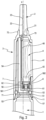
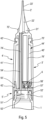
- the dispenser has a generally elongated shape along a longitudinal axis X.
- the dispenser generally resembles a pen or a felt-tip pen.
- the distributor is wider on the figure 1 that on the figure 2 , so that its cross section is oblong, ovoid or ellipsoidal.
- the dispenser generally comprises three parts, namely a reservoir 1 located in the lower part, an applicator 2 located in the upper part and a dispensing module 3 which is located axially between the reservoir 1 and the applicator 2. More specifically, reservoir 1 is connected to module 3 at its upper part and applicator 2 is also connected to module 3 at its lower part.
- the distribution module 3 it can be noted that it comprises a deformable actuation wall 41, which is located at the level of the greatest curvature of the distributor.
- the fluid reservoir 1 can be made from any suitable material, and preferably from a transparent or translucent material, so that the fluid it contains can be seen.
- Reservoir 1 has an elongated configuration along the longitudinal axis X and defines a closed bottom on one side and a neck 11 on the other side.
- the applicator 2 is here in the form of an elongated end piece along the longitudinal axis X.
- the applicator 2 comprises a fixing heel 21 which engages with the dispensing module, as will be seen below.
- the applicator 2 also comprises an internal channel 22 which ends in a dispensing orifice 23 located at the upper end of the applicator. It is possible to use any appropriate material to make the applicator 2, and advantageously a flexible material which confers a certain deformability on the applicator. This is only a particular, non-limiting embodiment. Indeed, the applicator can be of any kind, without departing from the scope of the invention.
- the applicator could also be in the form a piece of porous material, a spatula or even a brush. In itself, the nature and function of the applicator 2 is not critical for the present invention, insofar as it comprises a fixing heel 21 capable of coming into engagement with the dispensing module 3.
- the distribution module 3, in this first embodiment of the invention, comprises four constituent elements, namely an air pump 4, a module body 5, a one-piece valve member 6 and a cap 7.
- the air pump 4 is, in this embodiment, in the form of a one-piece air flush, which can for example be produced by injection blowing.
- the pump 4 defines at its lower end an opening 42 and laterally provided with a deformable actuation wall 41, which advantageously projects.
- Pump 4 internally forms a pump chamber 40.
- the module body 5 can advantageously be made in one piece and comprises at its lower end a fixing skirt 51 intended to come into leaktight engagement with the neck 11 of the reservoir 1. Inside this fixing skirt 51, the body module 5 defines an air outlet channel 52 and a fluid inlet well 53, which are arranged substantially side by side.
- the air outlet channel 51 communicates at its upper end with a valve housing 56 in which the one-piece valve member 6 is received. More specifically, with reference to the picture 3 , it can be seen that the valve housing 56 defines two separate valve seats 561 and 562, which cooperate with the one-piece valve member 6 so as to define an air outlet valve and an air inlet valve .
- the two valve seats 561 and 562 of the valve housing 56 are substantially concentric and the one-piece valve member 6 comprises an outer movable lip 62 and an inner movable lip 61.
- the inner movable lip 61 in cooperation with the inner valve seat 561 constitute the air outlet valve, while the outer movable lip 62 together with the outer valve seat 562 form the air inlet valve which is supplied with outside air from a venting passage 57.
- outlet well 53 communicates downstream with a fluid conduit 54 which leads to the applicator 2, as will be seen below.
- the cap 7 is in the form of a one-piece hollow body which houses the module body 5, the pump 4 and the one-piece valve member 6.
- the cap 7 defines at its lower end a receiving housing 71, in which is received, advantageously by snap-fastening, the neck 11 of the reservoir 1.
- the cap 7 defines an anchoring housing 72 in which is fixedly received the anchoring heel 21 of the applicator 2, advantageously by snap-fastening.
- the anchoring housing 72 At the bottom of the anchoring housing 72 is formed a passage hole 73 which communicates the fluid conduit 54 with the outlet channel 22 of the applicator 2.
- the cap 7 defines a large window 74 in which comes house the deformable actuation wall 41 of the pump 4, as can be seen in the figures 1, 2 And 3 .
- the dispenser includes a protective cap 8, which can snap in a removable manner on the cap 7, to hide and protect the applicator 2.
- This dispenser operates as follows: the user first grasps the dispenser with one hand, holding the cap 7 between the thumb and the middle finger, so as to be able to position his index finger on the wall of the dispenser. deformable actuation 41.
- the reservoir 1 is located higher than the applicator 2, so that the fluid product is present at the level of the outlet well 53.
- the air contained in the pump 4 is discharged through the opening 42, then forces the opening of the air outlet valve to be discharged through the air outlet channel 52 in the tank 1.
- the user By pressing on the deformable actuation wall 41, the user is not even aware that he is pushing air into the reservoir, with the consequence of pushing fluid product back through the conduit 54. At most, he may notice that air bubbles are released in the fluid product contained in the reservoir. This is particularly the case when the reservoir is made of a transparent material. It can also be noted that the reservoir does not include either a dip tube or a follower piston. The pressurized air thus rises in the reservoir 1 and the fluid product under pressure descends from the reservoir towards the applicator 2 through the conduit 54. The distribution module 3 thus makes it possible to cross the flow of air and the flow of product fluid.
- FIG. 5 And 6 one can see a second embodiment, in which the tank 1 and the one-piece valve member 6 can be strictly identical to those of the first embodiment of the figures 1 to 4 .
- the applicator 2' also has a somewhat different configuration, in the form of a spatula with a dispensing orifice 23' opening laterally.
- the essential difference with respect to the first embodiment resides in an architecture of the dispensing module 3′, and in particular the air pump 4′ and the fluid conduit which connects the reservoir to the applicator.
- This dispensing module 3' also comprises a module body 5' defining an attachment skirt 51' in engagement, advantageously snapped, with the neck 11 of the tank. Internally, the skirt 51' also defines an air outlet channel 52' and a fluid product outlet well 53'. The body 5' also defines a housing 56' for the one-piece valve member 6. In addition, the body 5' defines a sealed fixing flange 55', the function of which will be given below. Finally, the body 5' comprises a section of tube 58' which defines the lower part of a fluid product conduit 54' which extends from the well 53' upwards to the applicator 2'.
- the cap 7' also defines an anchoring housing 72' in which the anchoring heel 21' of the applicator 2' is received, advantageously by snap-fastening.
- the cap defines a watertight fastening flange 75', the function of which will be defined below.
- the cap 7' forms a tube 74' which defines the upper part of the fluid conduit 54'.
- the tubing 74' is fitted around the tube section 58'.
- the tubing 74' opens into the anchoring housing 72'.
- the tubing 74' with the section of tube 58' together form the fluid conduit 54' which connects the well 53' to the housing 72'.
- the cap 7' forms a tube 76' which extends around the tubing 74', or alternatively, the tubing 74' extends inside the tube 76'. The function of this tube 76' will be given below.
- the dispensing module 3' also comprises a flexible sleeve 4' whose lower end 42' is in tight engagement with the flange 55' and whose upper end 43' is in tight engagement with the flange 75'.
- the flexible sleeve 4' forms between its two ends a deformable actuation wall 41'.
- the flexible sleeve 4' surrounds the tubing 74' and the tube 76'.
- An air pump 44' is thus defined by the sleeve 4', the module body 5' and the cap 7'. This pump 44' defines a chamber 40' which is of annular cylindrical shape.
- this dispenser is globally as for that of the first embodiment. Indeed, when a user presses on the deformable actuation wall 41', air is pressurized inside the cuff 4'. The air outlet valve opens, so that the air flow passes through the outlet channel 52' and reaches the tank 1. Consequently, the pressure of the fluid product stored in reservoir 1 increases and part of this fluid product is discharged through well 53, then through section of tube 58', tubing 74' to reach outlet channel 22' of applicator 2' . The dispensed fluid product exits through the dispensing orifice 23', and the user can apply the fluid product to the desired surface. As soon as he releases the pressure on the deformable actuation wall 41', outside air enters the distributor through the vent hole 57' and opens the air inlet valve to restore atmospheric pressure to inside the 4' flexible sleeve.
- a fluid product dispenser/applicator which can take the form of a pen or a felt-tip pen, with a side actuation wall which does not act directly on the fluid product. , but through air, which is pressurized in an air pump.
- the air chamber of this air pump can extend alongside the fluid product channel which connects the reservoir to the applicator, or alternatively, it can extend all around this duct, as in the second mode of realization of the invention.
- the advantage of this air pump also lies in the fact that the reservoir 1 can only contain fluid product, and does not need a dip tube or a follower piston.
- the dispensing module 3 or 3' of the invention can be placed between any reservoir and any applicator.
Landscapes
- Containers And Packaging Bodies Having A Special Means To Remove Contents (AREA)
- Coating Apparatus (AREA)
- Nozzles (AREA)
Applications Claiming Priority (2)
| Application Number | Priority Date | Filing Date | Title |
|---|---|---|---|
| FR1855972A FR3083146B1 (fr) | 2018-06-29 | 2018-06-29 | Distributeur de produit fluide. |
| PCT/FR2019/051606 WO2020002854A1 (fr) | 2018-06-29 | 2019-06-28 | Distributeur de produit fluide |
Publications (2)
| Publication Number | Publication Date |
|---|---|
| EP3814019A1 EP3814019A1 (fr) | 2021-05-05 |
| EP3814019B1 true EP3814019B1 (fr) | 2023-08-16 |
Family
ID=63834168
Family Applications (1)
| Application Number | Title | Priority Date | Filing Date |
|---|---|---|---|
| EP19749774.6A Active EP3814019B1 (fr) | 2018-06-29 | 2019-06-28 | Distributeur de produit fluide |
Country Status (6)
| Country | Link |
|---|---|
| US (1) | US11292020B2 (zh) |
| EP (1) | EP3814019B1 (zh) |
| KR (1) | KR20210025053A (zh) |
| CN (1) | CN112384306B (zh) |
| FR (1) | FR3083146B1 (zh) |
| WO (1) | WO2020002854A1 (zh) |
Family Cites Families (37)
| Publication number | Priority date | Publication date | Assignee | Title |
|---|---|---|---|---|
| US248983A (en) * | 1881-11-01 | Sylvester w | ||
| US206653A (en) * | 1878-07-30 | Improvement in syringe apparatus | ||
| US1577539A (en) * | 1922-08-28 | 1926-03-23 | Polk Alexander Hamilton | Dispensing device |
| US1776489A (en) * | 1928-03-12 | 1930-09-23 | Carolus M Cobb | Powder distributor |
| US1808662A (en) * | 1928-04-20 | 1931-06-02 | Kline Max | Atomizer |
| US2223256A (en) * | 1938-12-27 | 1940-11-26 | Mark R Kross | Liquid separating device |
| US3940030A (en) * | 1974-08-16 | 1976-02-24 | Hirosi Kondo | Dispenser device for taking out contents |
| JPS61133Y2 (zh) * | 1977-10-20 | 1986-01-07 | ||
| FR2586233B1 (fr) * | 1985-08-13 | 1987-11-27 | Oreal | Dispositif de distribution en quantites dosees d'au moins un produit relativement visqueux |
| DE8601783U1 (de) * | 1986-01-24 | 1986-06-05 | Tunap Deutschland Vertriebs GmbH + Co KG, 8190 Wolfratshausen | Druckluftbetriebene Versprüheinrichtung für Flüssigkeiten |
| IT1230221B (it) * | 1989-05-29 | 1991-10-18 | Vasapollo Giuseppe Pietrasanta | Nebulizzatore ecologico ad aria compressa ad azionamento manuale. |
| DE3928156A1 (de) * | 1989-08-25 | 1991-02-28 | Bayer Ag | Vorrichtung und verfahren zum aufspruehen einer zahnaerztlichen abformmasse |
| DK302890D0 (da) * | 1990-12-21 | 1990-12-21 | Novo Nordisk As | Dispenser |
| CN2159217Y (zh) * | 1993-03-20 | 1994-03-23 | 刘波 | 医用多功能抽吸器 |
| FR2765560B1 (fr) * | 1997-07-02 | 1999-08-13 | Oreal | Distributeur pour un produit liquide ou pateux comportant des moyens de pompage ameliores |
| US6200055B1 (en) * | 1999-06-18 | 2001-03-13 | Stephen Gould Corporation | Dispenser device for dispensing metered doses of viscous material |
| FR2852933B1 (fr) | 2003-03-24 | 2005-05-13 | Airlessystems | Distributeur de produit fluide. |
| US7140522B2 (en) * | 2003-06-26 | 2006-11-28 | Spencer Forrest, Inc. | Applicator for hair building solids |
| FR2863938B1 (fr) * | 2003-12-19 | 2006-03-03 | Bic Soc | Instrumentd'ecriture a jet de liquide |
| JP2008514310A (ja) * | 2004-09-27 | 2008-05-08 | メディカル・インスティル・テクノロジーズ・インコーポレイテッド | 物質の貯蔵および定量分注用の一方向弁を有する横方向作動分注器 |
| TWI391301B (zh) * | 2005-04-25 | 2013-04-01 | Advanced Tech Materials | 物料儲存及配送包裝及方法 |
| WO2007040133A1 (ja) * | 2005-10-03 | 2007-04-12 | Mika Watanabe | 手動ポンプ及び手動ポンプ付き液体容器 |
| US7841494B2 (en) * | 2007-03-16 | 2010-11-30 | Randall Batinkoff | Pump dispenser |
| JP4309443B2 (ja) * | 2007-08-29 | 2009-08-05 | 株式会社トンボ鉛筆 | 加圧ペン |
| JP5785755B2 (ja) * | 2010-04-02 | 2015-09-30 | 花王株式会社 | 内容物押出容器 |
| US9321064B2 (en) * | 2010-09-24 | 2016-04-26 | Blake Vanier | Drinking vessel with pump and methods |
| DE102011007405A1 (de) * | 2011-04-14 | 2012-10-18 | Ing. Erich Pfeiffer Gmbh | Kosmetik-Spender |
| FR2978684B1 (fr) | 2011-08-01 | 2013-08-23 | Valois Sas | Tete de distribution et d'application. |
| US9393583B2 (en) * | 2012-08-30 | 2016-07-19 | Zhejiang Jm Industry Co., Ltd. | Powder dispenser |
| CN104058180B (zh) * | 2013-03-18 | 2017-03-01 | F·霍尔泽有限责任公司 | 药剂分配器 |
| WO2015003762A1 (de) * | 2013-07-09 | 2015-01-15 | Gerhard Brugger | Dosierspender für das austragen eines insbesondere pastösen oder viskosen materials, wie etwa kosmetikcremes, klebemittel und dergleichen |
| FR3020748B1 (fr) * | 2014-05-07 | 2020-10-30 | Aptar France Sas | Ensemble de distribution et d'application de produit fluide |
| AU2014409667B2 (en) * | 2014-10-28 | 2018-04-19 | Ya-Man Limited | Airbrush |
| CA2885599A1 (en) * | 2015-03-20 | 2016-09-20 | Vincent Cheng | Wall paint repair tool |
| CN205849001U (zh) * | 2016-07-29 | 2017-01-04 | 江阴和盛塑胶有限公司 | 一种侧压式真空瓶 |
| CN107605899A (zh) * | 2017-09-25 | 2018-01-19 | 天津市凌宇金属制品制造有限公司 | 胶液注射式强力铁钉 |
| EP3704448B1 (en) | 2017-11-02 | 2022-06-01 | F. Hoffmann-La Roche AG | Droplet dispensing device and system |
-
2018
- 2018-06-29 FR FR1855972A patent/FR3083146B1/fr active Active
-
2019
- 2019-06-28 CN CN201980044198.4A patent/CN112384306B/zh active Active
- 2019-06-28 WO PCT/FR2019/051606 patent/WO2020002854A1/fr active Application Filing
- 2019-06-28 EP EP19749774.6A patent/EP3814019B1/fr active Active
- 2019-06-28 US US17/252,027 patent/US11292020B2/en active Active
- 2019-06-28 KR KR1020217001412A patent/KR20210025053A/ko not_active Application Discontinuation
Also Published As
| Publication number | Publication date |
|---|---|
| US20210252537A1 (en) | 2021-08-19 |
| CN112384306B (zh) | 2023-11-10 |
| WO2020002854A1 (fr) | 2020-01-02 |
| FR3083146A1 (fr) | 2020-01-03 |
| KR20210025053A (ko) | 2021-03-08 |
| CN112384306A (zh) | 2021-02-19 |
| EP3814019A1 (fr) | 2021-05-05 |
| US11292020B2 (en) | 2022-04-05 |
| FR3083146B1 (fr) | 2020-06-19 |
Similar Documents
| Publication | Publication Date | Title |
|---|---|---|
| EP1313568B1 (fr) | Distributeur a pompe integree | |
| EP1814672B1 (fr) | Piece souple formant le clapet de sortie et le ressort de rappel d'un organe de distribution | |
| EP2838667B1 (fr) | Reservoir de produit fluide et distributeur utilisant un tel reservoir. | |
| EP2442914B1 (fr) | Distributeur de produit fluide | |
| EP2004333A1 (fr) | Pompe de distribution de produit fluide | |
| EP1626813A2 (fr) | Distributeur de produit fluide et procede de montage d'un tel distributeur | |
| EP3451870B1 (fr) | Dispositif pour le conditionnement et la distribution d'un produit, notamment d'un produit cosmétique | |
| EP3592470B1 (fr) | Dispositif de distribution d'un produit avec amorçage amélioré | |
| FR2884157A1 (fr) | Tete de distribution | |
| EP2036617A1 (fr) | Pompe distributrice pour récipient de stockage et de distribution de produit et récipient pourvu d'une telle pompe | |
| EP2069077B1 (fr) | Dispositif de distribution de produit fluide | |
| EP3743210B1 (fr) | Procédé de montage d'un distributeur de produit fluide | |
| EP3814019B1 (fr) | Distributeur de produit fluide | |
| WO2003018208A1 (fr) | Tete de distribution pour distributeur de produit fluide | |
| EP3953054B1 (fr) | Distributeur de produit fluide rechargeable | |
| EP2874757B1 (fr) | Distributeur de produit fluide | |
| EP4064927B1 (fr) | Dispositif de distribution de produit liquide ou pâteux | |
| WO2017129883A1 (fr) | Distributeur de produit fluide rechargeable. | |
| WO2004054724A1 (fr) | Pompe manuelle pour la distribution de liquides pulverises a etancheite optimisee |
Legal Events
| Date | Code | Title | Description |
|---|---|---|---|
| STAA | Information on the status of an ep patent application or granted ep patent |
Free format text: STATUS: UNKNOWN |
|
| STAA | Information on the status of an ep patent application or granted ep patent |
Free format text: STATUS: THE INTERNATIONAL PUBLICATION HAS BEEN MADE |
|
| STAA | Information on the status of an ep patent application or granted ep patent |
Free format text: STATUS: THE INTERNATIONAL PUBLICATION HAS BEEN MADE |
|
| PUAI | Public reference made under article 153(3) epc to a published international application that has entered the european phase |
Free format text: ORIGINAL CODE: 0009012 |
|
| STAA | Information on the status of an ep patent application or granted ep patent |
Free format text: STATUS: REQUEST FOR EXAMINATION WAS MADE |
|
| 17P | Request for examination filed |
Effective date: 20210125 |
|
| AK | Designated contracting states |
Kind code of ref document: A1 Designated state(s): AL AT BE BG CH CY CZ DE DK EE ES FI FR GB GR HR HU IE IS IT LI LT LU LV MC MK MT NL NO PL PT RO RS SE SI SK SM TR |
|
| DAV | Request for validation of the european patent (deleted) | ||
| DAX | Request for extension of the european patent (deleted) | ||
| STAA | Information on the status of an ep patent application or granted ep patent |
Free format text: STATUS: EXAMINATION IS IN PROGRESS |
|
| 17Q | First examination report despatched |
Effective date: 20221005 |
|
| GRAP | Despatch of communication of intention to grant a patent |
Free format text: ORIGINAL CODE: EPIDOSNIGR1 |
|
| STAA | Information on the status of an ep patent application or granted ep patent |
Free format text: STATUS: GRANT OF PATENT IS INTENDED |
|
| INTG | Intention to grant announced |
Effective date: 20230315 |
|
| GRAS | Grant fee paid |
Free format text: ORIGINAL CODE: EPIDOSNIGR3 |
|
| GRAA | (expected) grant |
Free format text: ORIGINAL CODE: 0009210 |
|
| STAA | Information on the status of an ep patent application or granted ep patent |
Free format text: STATUS: THE PATENT HAS BEEN GRANTED |
|
| AK | Designated contracting states |
Kind code of ref document: B1 Designated state(s): AL AT BE BG CH CY CZ DE DK EE ES FI FR GB GR HR HU IE IS IT LI LT LU LV MC MK MT NL NO PL PT RO RS SE SI SK SM TR |
|
| RIN1 | Information on inventor provided before grant (corrected) |
Inventor name: MOREAU, FRANCIS Inventor name: DUQUET, FREDERIC |
|
| REG | Reference to a national code |
Ref country code: CH Ref legal event code: EP Ref country code: DE Ref legal event code: R096 Ref document number: 602019035154 Country of ref document: DE |
|
| REG | Reference to a national code |
Ref country code: IE Ref legal event code: FG4D Free format text: LANGUAGE OF EP DOCUMENT: FRENCH |
|
| P01 | Opt-out of the competence of the unified patent court (upc) registered |
Effective date: 20230913 |
|
| REG | Reference to a national code |
Ref country code: LT Ref legal event code: MG9D |
|
| REG | Reference to a national code |
Ref country code: NL Ref legal event code: MP Effective date: 20230816 |
|
| REG | Reference to a national code |
Ref country code: AT Ref legal event code: MK05 Ref document number: 1599516 Country of ref document: AT Kind code of ref document: T Effective date: 20230816 |
|
| PG25 | Lapsed in a contracting state [announced via postgrant information from national office to epo] |
Ref country code: GR Free format text: LAPSE BECAUSE OF FAILURE TO SUBMIT A TRANSLATION OF THE DESCRIPTION OR TO PAY THE FEE WITHIN THE PRESCRIBED TIME-LIMIT Effective date: 20231117 |
|
| PG25 | Lapsed in a contracting state [announced via postgrant information from national office to epo] |
Ref country code: IS Free format text: LAPSE BECAUSE OF FAILURE TO SUBMIT A TRANSLATION OF THE DESCRIPTION OR TO PAY THE FEE WITHIN THE PRESCRIBED TIME-LIMIT Effective date: 20231216 |
|
| PG25 | Lapsed in a contracting state [announced via postgrant information from national office to epo] |
Ref country code: SE Free format text: LAPSE BECAUSE OF FAILURE TO SUBMIT A TRANSLATION OF THE DESCRIPTION OR TO PAY THE FEE WITHIN THE PRESCRIBED TIME-LIMIT Effective date: 20230816 Ref country code: RS Free format text: LAPSE BECAUSE OF FAILURE TO SUBMIT A TRANSLATION OF THE DESCRIPTION OR TO PAY THE FEE WITHIN THE PRESCRIBED TIME-LIMIT Effective date: 20230816 Ref country code: PT Free format text: LAPSE BECAUSE OF FAILURE TO SUBMIT A TRANSLATION OF THE DESCRIPTION OR TO PAY THE FEE WITHIN THE PRESCRIBED TIME-LIMIT Effective date: 20231218 Ref country code: NO Free format text: LAPSE BECAUSE OF FAILURE TO SUBMIT A TRANSLATION OF THE DESCRIPTION OR TO PAY THE FEE WITHIN THE PRESCRIBED TIME-LIMIT Effective date: 20231116 Ref country code: NL Free format text: LAPSE BECAUSE OF FAILURE TO SUBMIT A TRANSLATION OF THE DESCRIPTION OR TO PAY THE FEE WITHIN THE PRESCRIBED TIME-LIMIT Effective date: 20230816 Ref country code: LV Free format text: LAPSE BECAUSE OF FAILURE TO SUBMIT A TRANSLATION OF THE DESCRIPTION OR TO PAY THE FEE WITHIN THE PRESCRIBED TIME-LIMIT Effective date: 20230816 Ref country code: LT Free format text: LAPSE BECAUSE OF FAILURE TO SUBMIT A TRANSLATION OF THE DESCRIPTION OR TO PAY THE FEE WITHIN THE PRESCRIBED TIME-LIMIT Effective date: 20230816 Ref country code: IS Free format text: LAPSE BECAUSE OF FAILURE TO SUBMIT A TRANSLATION OF THE DESCRIPTION OR TO PAY THE FEE WITHIN THE PRESCRIBED TIME-LIMIT Effective date: 20231216 Ref country code: HR Free format text: LAPSE BECAUSE OF FAILURE TO SUBMIT A TRANSLATION OF THE DESCRIPTION OR TO PAY THE FEE WITHIN THE PRESCRIBED TIME-LIMIT Effective date: 20230816 Ref country code: GR Free format text: LAPSE BECAUSE OF FAILURE TO SUBMIT A TRANSLATION OF THE DESCRIPTION OR TO PAY THE FEE WITHIN THE PRESCRIBED TIME-LIMIT Effective date: 20231117 Ref country code: FI Free format text: LAPSE BECAUSE OF FAILURE TO SUBMIT A TRANSLATION OF THE DESCRIPTION OR TO PAY THE FEE WITHIN THE PRESCRIBED TIME-LIMIT Effective date: 20230816 Ref country code: AT Free format text: LAPSE BECAUSE OF FAILURE TO SUBMIT A TRANSLATION OF THE DESCRIPTION OR TO PAY THE FEE WITHIN THE PRESCRIBED TIME-LIMIT Effective date: 20230816 |
|
| PG25 | Lapsed in a contracting state [announced via postgrant information from national office to epo] |
Ref country code: PL Free format text: LAPSE BECAUSE OF FAILURE TO SUBMIT A TRANSLATION OF THE DESCRIPTION OR TO PAY THE FEE WITHIN THE PRESCRIBED TIME-LIMIT Effective date: 20230816 |
|
| PG25 | Lapsed in a contracting state [announced via postgrant information from national office to epo] |
Ref country code: ES Free format text: LAPSE BECAUSE OF FAILURE TO SUBMIT A TRANSLATION OF THE DESCRIPTION OR TO PAY THE FEE WITHIN THE PRESCRIBED TIME-LIMIT Effective date: 20230816 |
|
| PG25 | Lapsed in a contracting state [announced via postgrant information from national office to epo] |
Ref country code: SM Free format text: LAPSE BECAUSE OF FAILURE TO SUBMIT A TRANSLATION OF THE DESCRIPTION OR TO PAY THE FEE WITHIN THE PRESCRIBED TIME-LIMIT Effective date: 20230816 Ref country code: RO Free format text: LAPSE BECAUSE OF FAILURE TO SUBMIT A TRANSLATION OF THE DESCRIPTION OR TO PAY THE FEE WITHIN THE PRESCRIBED TIME-LIMIT Effective date: 20230816 Ref country code: ES Free format text: LAPSE BECAUSE OF FAILURE TO SUBMIT A TRANSLATION OF THE DESCRIPTION OR TO PAY THE FEE WITHIN THE PRESCRIBED TIME-LIMIT Effective date: 20230816 Ref country code: EE Free format text: LAPSE BECAUSE OF FAILURE TO SUBMIT A TRANSLATION OF THE DESCRIPTION OR TO PAY THE FEE WITHIN THE PRESCRIBED TIME-LIMIT Effective date: 20230816 Ref country code: DK Free format text: LAPSE BECAUSE OF FAILURE TO SUBMIT A TRANSLATION OF THE DESCRIPTION OR TO PAY THE FEE WITHIN THE PRESCRIBED TIME-LIMIT Effective date: 20230816 Ref country code: CZ Free format text: LAPSE BECAUSE OF FAILURE TO SUBMIT A TRANSLATION OF THE DESCRIPTION OR TO PAY THE FEE WITHIN THE PRESCRIBED TIME-LIMIT Effective date: 20230816 Ref country code: SK Free format text: LAPSE BECAUSE OF FAILURE TO SUBMIT A TRANSLATION OF THE DESCRIPTION OR TO PAY THE FEE WITHIN THE PRESCRIBED TIME-LIMIT Effective date: 20230816 |