EP3808420B1 - Spannhebel als stanz- oder schnittteil - Google Patents
Spannhebel als stanz- oder schnittteil Download PDFInfo
- Publication number
- EP3808420B1 EP3808420B1 EP20200244.0A EP20200244A EP3808420B1 EP 3808420 B1 EP3808420 B1 EP 3808420B1 EP 20200244 A EP20200244 A EP 20200244A EP 3808420 B1 EP3808420 B1 EP 3808420B1
- Authority
- EP
- European Patent Office
- Prior art keywords
- tensing
- lever
- ski binding
- front jaw
- moulded
- Prior art date
- Legal status (The legal status is an assumption and is not a legal conclusion. Google has not performed a legal analysis and makes no representation as to the accuracy of the status listed.)
- Active
Links
Images


Classifications
-
- A—HUMAN NECESSITIES
- A63—SPORTS; GAMES; AMUSEMENTS
- A63C—SKATES; SKIS; ROLLER SKATES; DESIGN OR LAYOUT OF COURTS, RINKS OR THE LIKE
- A63C9/00—Ski bindings
- A63C9/08—Ski bindings yieldable or self-releasing in the event of an accident, i.e. safety bindings
- A63C9/0807—Ski bindings yieldable or self-releasing in the event of an accident, i.e. safety bindings for both towing and downhill skiing
-
- A—HUMAN NECESSITIES
- A63—SPORTS; GAMES; AMUSEMENTS
- A63C—SKATES; SKIS; ROLLER SKATES; DESIGN OR LAYOUT OF COURTS, RINKS OR THE LIKE
- A63C9/00—Ski bindings
- A63C9/08—Ski bindings yieldable or self-releasing in the event of an accident, i.e. safety bindings
- A63C9/085—Ski bindings yieldable or self-releasing in the event of an accident, i.e. safety bindings with sole hold-downs, e.g. swingable
- A63C9/08507—Ski bindings yieldable or self-releasing in the event of an accident, i.e. safety bindings with sole hold-downs, e.g. swingable with a plurality of mobile jaws
- A63C9/08528—Ski bindings yieldable or self-releasing in the event of an accident, i.e. safety bindings with sole hold-downs, e.g. swingable with a plurality of mobile jaws pivoting about a longitudinal axis
-
- A—HUMAN NECESSITIES
- A63—SPORTS; GAMES; AMUSEMENTS
- A63C—SKATES; SKIS; ROLLER SKATES; DESIGN OR LAYOUT OF COURTS, RINKS OR THE LIKE
- A63C9/00—Ski bindings
- A63C9/08—Ski bindings yieldable or self-releasing in the event of an accident, i.e. safety bindings
- A63C9/085—Ski bindings yieldable or self-releasing in the event of an accident, i.e. safety bindings with sole hold-downs, e.g. swingable
- A63C9/08557—Details of the release mechanism
- A63C9/08578—Details of the release mechanism using a plurality of biasing elements
-
- A—HUMAN NECESSITIES
- A63—SPORTS; GAMES; AMUSEMENTS
- A63C—SKATES; SKIS; ROLLER SKATES; DESIGN OR LAYOUT OF COURTS, RINKS OR THE LIKE
- A63C9/00—Ski bindings
- A63C9/08—Ski bindings yieldable or self-releasing in the event of an accident, i.e. safety bindings
- A63C9/085—Ski bindings yieldable or self-releasing in the event of an accident, i.e. safety bindings with sole hold-downs, e.g. swingable
- A63C9/08557—Details of the release mechanism
- A63C9/08585—Details of the release mechanism using transverse biasing element
-
- A—HUMAN NECESSITIES
- A63—SPORTS; GAMES; AMUSEMENTS
- A63C—SKATES; SKIS; ROLLER SKATES; DESIGN OR LAYOUT OF COURTS, RINKS OR THE LIKE
- A63C9/00—Ski bindings
- A63C9/08—Ski bindings yieldable or self-releasing in the event of an accident, i.e. safety bindings
- A63C9/086—Ski bindings yieldable or self-releasing in the event of an accident, i.e. safety bindings using parts which are fixed on the shoe of the user and are releasable from the ski binding
Definitions
- the invention relates to a toe piece for a touring ski binding, which has a clamping device for holding a ski boot in the touring ski binding, wherein the clamping device comprises a clamping lever which is at least partially a punched part punched out of a material plate.
- Touring ski bindings are used not only for downhill skiing but also primarily for ascending slopes. In addition to the weight of the touring ski binding, price is also a factor that influences the customer's purchasing decision. Potential savings in manufacturing costs can be realized, for example, by reducing the production time for individual touring ski binding components. This time saving can be achieved, for example, by replacing a standard manufacturing process with a different, more cost-effective, simpler, and/or faster manufacturing process. This means that the manufacturer is tasked with reviewing the costs incurred at every manufacturing step of each touring ski binding component and seeking more cost-effective manufacturing methods.
- the touring ski binding "Plum R150" for example, has a generic toe piece (URL: https://www.fixation-plum.com/de/our-bindings/1210-race-150.html).
- the subject of the invention is a toe piece for a touring ski binding, comprising a base and a bearing arrangement which is designed to pivotably hold a ski boot about a transverse ski axis running transversely to a ski binding longitudinal axis, so that the ski boot can be moved between a first pivot position in which a heel section of the ski boot is closer to the ski, and a second pivot position in which the heel section of the ski boot is further away from the ski, wherein the toe piece has a clamping device with which the The bearing arrangement can be locked in such a way that pivoting of the ski boot is possible, but detachment of the ski boot from the bearing arrangement is prevented even when a fall-triggering force is exerted.
- the tensioning device comprises a tensioning element and a tensioning lever, the tensioning lever being connectable to the base in a pivot joint.
- the tensioning lever has a free end in the lever's longitudinal direction, which end comprises a tensioning lever head with a tensioning lever mouth.
- the tensioning lever mouth is adapted to be coupled to a mechanism of the toe piece, the mechanism tensioning and releasing the bearing arrangement of the toe piece.
- the clamping lever or at least a portion of the clamping lever, is punched out of a sheet of material as a stamped part.
- the stamped part can be single-layered or composed of multiple layers, each of which is manufactured as a stamped part. Two or more layers can be joined to form the aforementioned part of the clamping lever following the stamping process.
- the touring ski binding also comprises a heel piece, in which the ski boot is held at a rear end or heel end during downhill skiing.
- the heel piece can be moved linearly relative to the ski, for example, or pivoted about an axis that is directed upwards substantially perpendicular to a ski surface, in order to transfer the touring ski binding from downhill mode to touring mode.
- the heel piece can be a known heel piece, for example with an automatic mechanism that presses against a surface of a rear end of the ski boot sole, or a heel piece with at least one engagement element that engages with at least one counter-engagement element formed in the ski boot sole in the region of the heel end, or another known heel piece.
- the heel piece can form at least one climbing aid and/or comprise at least one climbing aid that is adjustable relative to the heel piece.
- the bearing arrangement can be two engagement elements opposite one another with respect to a ski central longitudinal axis, which are each connected in the region of a first free end of a first or second arm, wherein a second free end of the first and second arms are pivotally held in the toe piece.
- the first and second arms can be pivoted synchronously into a first position and a second position by means of the mechanism.
- the two engagement elements are at a maximum distance from one another so that a user can step into the toe piece with a ski boot.
- the two engagement elements are at a distance from one another which is smaller than the maximum distance in the first position.
- the two engagement elements define a pivot axis for the pivoting movement of the ski boot.
- the engagement elements can engage in openings formed in a ski boot sole and thereby connect the ski boot to the ski at the front end or toe end in touring mode. Ski bindings with such toe pieces are also referred to as pin bindings.
- touring ski bindings have tensioning devices to lock the bearing assembly during ascent, allowing the ski boot to pivot, but preventing the ski boot from detaching from the bearing assembly even when a fall-triggering force is applied.
- the unlocked state of the bearing assembly is desirable during downhill skiing, allowing the touring ski binding to open when a fall-triggering force is sufficiently high, releasing the ski boot and thus preventing injury.
- the release of the ski boot from the touring ski binding in the event of a fall, lateral load or load in or against the direction of travel above an adjustable limit can be achieved by the front piece and/or the rear piece.
- the material of the material plate or plates can be a plastic, in particular a reinforced plastic, steel, aluminum, magnesium, or an alloy comprising at least one of these materials.
- Alternative materials are possible as long as they have the necessary strength under the expected environmental conditions for a touring ski binding. This means that in a multi-layer construction, the aforementioned part of the tensioning lever can be formed from layers of one material or from layers of different materials. If multiple layers connected to one another, not all layers have to be fully bonded, which can save material and weight.
- At least one layer can consist of a solid material, in particular a metal, while at least one of the other layers, for example of plastic, can have a skeletal structure, preferably with a closed outer side, which can form a lateral surface of the tensioning lever. It can also be advantageous, for example, to arrange a corrosion-prone material between two layers where no corrosion problems are expected for the lifetime of the product.
- the manufacturing technique chosen for producing the clamping lever, in particular the at least one solid material part is punching out of the material plate by means of a punching device or punch.
- the clamping lever can be connected to the clamping element in a further swivel joint, particularly in a captive manner.
- a rivet can form a rotation axis of the further swivel joint. The rivet can hold the clamping lever in the further swivel joint in a rotatable or pivotable manner and captive in the clamping element.
- the tensioning lever can be elongated and has a free end in the tensioning lever or lever longitudinal direction, which encompasses the tensioning lever head with the tensioning lever mouth.
- a tensioning lever longitudinal axis can run parallel to the ski binding longitudinal axis, at least in one pivot position, possibly in a pivot position of the tensioning lever that is only theoretically achievable.
- the clamping lever mouth is designed to be coupled to a mechanism of the toe piece or to engage with this mechanism.
- a pivoting movement of the clamping lever can preferably be transmitted to the mechanism.
- the mechanism can be designed to tension the bearing arrangement of the toe piece so that the ski boot is held in the bearing arrangement, and to relax it to release the ski boot from the bearing arrangement.
- the clamping lever can be formed solely by the at least one stamped part.
- the clamping lever can be constructed in a sandwich design, wherein the stamped part is arranged between at least one first mold plate and at least one second mold plate, such that one of the mold plates forms a left outer side and another of the mold plates forms a right outer side of the clamping lever.
- the first mold plate and the second mold plate can be separate mold plates that are individually joined to the stamped part.
- the first mold plate and the second mold plate can be connected to one another, preferably molded in one piece, and form a clamping lever housing that at least partially encompasses the stamped part.
- the first mold plate and the second mold plate, or the clamping lever housing can be made of a plastic, preferably using a plastic injection molding or deep-drawing process. They can be three-dimensional, for example, as a hollow body with a molded reinforcement structure, and have a printable surface so that they can be adapted to any design.
- the mold plates can also be made of a clear or transparent material or plastic, which can be printed on its inside, for example.
- the mold plates can have sections made of different materials, for example, they can be manufactured using a two- or multi-component plastic injection molding process or they can include inserts that are overmolded with plastic.
- the first mold plate and the second mold plate are joined to the punched part, preferably by positive and/or material bonding.
- Material bonding can be understood, for example, as a connection by means of an adhesive.
- An outer peripheral shape of the support surface of the first and second mold plates, which bears against the punched part, can essentially correspond to the outer peripheral shape of the punched part.
- the form-fitting and/or material-locking connection connects the punched part to the first mold plate and the second mold plate, preferably elastically, so that, for example, a temperature-dependent, different expansion between the punched part can be compensated by the elastic connection. It is preferred if the material of the stamped part and the material of the first and second mold plate, or of the clamping lever housing, has a similar, preferably substantially identical, coefficient of linear expansion in a temperature range between -30°C to +40°C, preferably between -25°C and +35°C and particularly preferably -20°C and +30°C.
- the first mold plate and the second mold plate have a longitudinal extent that is smaller than a longitudinal extent of the punched part, so that the clamping lever mouth, or a tongue of the clamping lever mouth, protrudes at least partially beyond the first and the second mold plate in the direction of the mechanism for clamping and releasing the clamping device.
- the stamped part is preferably positively connected to the tension lever housing.
- the stamped part can be connected to the tension lever housing and secured to the tension lever housing, in particular by means of one or more riveted connections.
- the rivet can be part of the first pivot joint and/or the second pivot joint.
- the stamped part can be glued to the molded parts or the tension lever housing.
- the tension lever housing can be connected to the stamped part via a screw body and/or by means of an adhesive.
- one of the stamped part and the tension lever housing can comprise an engagement element that engages with a counter-engagement element of the other of the stamped part and the tension lever housing.
- the counter-engagement element can, for example, be a slot or a through-opening in the stamped part, which is already created during the stamping process, so that no further processing step is necessary. However, the counter-engagement element can also be created in a subsequent processing step. Accordingly, the engagement element can be formed by the tension lever housing.
- the clamping element can be connected to the clamping lever in a pivot joint, preferably in a captive manner, and can be pivoted relative to the clamping lever in the pivot joint.
- the clamping lever can be located within the clamping element, at least in one pivot position, with one end facing away from the clamping lever head, meaning that it can be at least partially surrounded by the clamping element.
- the clamping lever can be connected to the base via an additional pivot joint and can be pivoted relative to the base.
- the pivot joint in which the clamping element is connected to the clamping lever, can be positioned after or behind the additional pivot joint in the longitudinal direction of the ski, i.e., closer to the tip of the ski.
- the base can be designed to be connected directly to a ski or via one or more intermediate elements.
- the tensioning element can have a contact device which, when the tensioning element is pivoted about the pivot joint connecting the tensioning element to the tensioning lever, is brought into and out of contact with a contact surface of the base.
- the contact surface serves, for example, as a stop for the contact device of the tensioning element and, in the locked position—i.e., when there is contact between the contact device and the contact surface—limits the movement of the tensioning lever.
- the bearing arrangement is locked by the coupling of the tensioning lever to the bearing arrangement via a mechanism, so that a ski boot located in the toe piece cannot detach from the bearing arrangement, even when a force is exerted that could trigger a fall. This condition is desirable and advantageous when ascending with touring ski bindings.
- the stamped part can have at least three clearly defined sections: a first section, which comprises a receptacle or an opening for a joint axis of the swivel joint that connects the clamping lever to the clamping element; a second section adjoining the first section, which can be designed to allow the required mobility of the clamping lever in the front jaw and/or to form a locking mechanism for the contact device in at least one pivoting position; and a third section adjoining the second section, which comprises a receptacle or an opening for the joint axis of the swivel joint, which preferably connects the stamped part to the base, and the clamping lever head with the clamping lever mouth.
- the mold plates or the clamping lever housing can also have these sections. with the exception that the clamping lever head with the clamping lever mouth is not or at least only partially covered by the mold plates or the clamping lever housing.
- the first and/or second mold plate or the clamping lever housing can have at least three regions: a first region comprising a receptacle for the pivot joint that connects the clamping lever to the clamping element; a second region adjoining the first region and designed to form a latch for the contact device when the contact device is in a pivoting position; and a third region adjoining the second region and comprising a receptacle for a pivot joint that preferably connects the stamped part to the base.
- the stamped part comprises the clamping lever head with the clamping lever mouth; and at least one tongue or part of the tongue of the clamping lever mouth can protrude beyond one end of the first and second mold plates in the longitudinal direction of the front jaw.
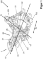
- the Figure 1 shows a toe piece 100 for a touring ski binding.
- the toe piece 100 comprises a base 103, via which the toe piece 100 can be connected to a ski (not shown).
- the toe piece 100 comprises a Bearing arrangement 101, which in the exemplary embodiment consists of two pins that are intended to engage in receptacles of a ski boot (not shown).
- the bearing arrangement 101 or the pins firmly connect the toe piece 100 to the ski boot in a first position and form an axis that runs in a transverse direction Q to a longitudinal axis L of the toe piece 100.
- the ski boot can be pivoted about the axis from a first position, in which the ski boot sole runs substantially parallel to an upper side of the ski and the heel section of the ski boot is closer to the ski, to a second position, in which the ski boot sole forms an acute angle with the upper side of the ski and the heel section of the ski boot is further away from the ski.
- the toe piece 100 comprises a clamping device 1 with a clamping element 10 and a clamping lever 20.
- the clamping element 10 and the clamping lever 20 are connected to one another at a pivot joint D1.
- the clamping lever 20 is connected to the base 103 at a pivot joint D2.
- the clamping lever 20 acts on a mechanism 102 that is connected to the bearing arrangement 101, or rather the pins, in order to move them into the first position, in which the bearing arrangement 101 is connected to the ski boot, and from the first position into a second position, in which the ski boot can be removed from the toe piece 100.
- the clamping lever 20 consists of several parts that are joined together.
- the clamping lever 20 consists of a central part or core that is punched out of a sheet material and is therefore also referred to as a punched part 21.
- the stamped part 21 is preferably formed from a metal, for example from aluminum, steel, magnesium, another suitable metal, or from an alloy comprising at least one of the aforementioned metals.
- the middle part can also consist of more than one stamped part 21, which are joined together to form the middle part. If the middle part consists of more than one stamped part 21, the stamped parts can 21 may be made of different materials, for example different metals or metal alloys.
- the mold plates 24, 25 are joined to the stamped part 21, forming a right and a left side of the clamping lever 20.
- the mold plates 24, 25 can also be made of metal, but they are preferably plastic parts, which are produced, for example, by injection molding, deep-drawing, or another suitable manufacturing process. Suitable plastics include, without claiming to be exhaustive, polypropylene, polyethylene, polystyrene, PMMA, ABS, or ASA/ABS.
- the punched part 21 can, for example, have a longitudinal slot in the central area to save weight. This slot is created during the punching process, for example, since this does not require additional time, unlike cutting, for example. Openings at other locations are conceivable, and their suitability can easily be verified by a specialist through testing.
- the mold plates 24, 25 can be shell-shaped, partially shell-shaped, or made of solid material.
- Shell-shaped or partially shell-shaped mold plates 24, 25 can have integrated reinforcing structures, such as reinforcing ribs, reinforcing studs, etc., to prevent the shell from collapsing or being dented when subjected to force from the side.
- the mold plates 24, 25 can be made of different materials in certain areas, for example, different plastics or partially of natural materials, such as compostable natural fibers, to provide a further advantage for the application.
- the Figure 2 shows a section through the toe piece 100 along a ski binding longitudinal axis L.
- the punched part 21 is clearly visible.
- the punched part 21 has an opening or a receptacle 52, which is part of the pivot joint D1 or at least accommodates the pivot joint D1, in which the clamping element 10 can be rotatably connected to the clamping lever 20.
- an opening or a Recess 53 is formed in the stamped part 21, which forms part of the pivot joint D2 or at least accommodates the pivot joint D2, in which the clamping lever 20 can be rotatably connected to the base 103.
- the stamped part 21 comprises, at its end facing the mechanism 102, a clamping lever head 22 with a clamping lever mouth 23.
- the clamping lever mouth 23 couples with the mechanism 102, so that a movement of the clamping lever 20 is transmitted directly to the mechanism 102.
- the tensioning lever 20 presses the mechanism 102 downwards close to the base 103, whereby the contact device 11, or the pins, are pressed against the ski boot (not shown) or into recesses in the ski boot sole.
- the clamping element 10 comprises a contact device 11, which interacts with a contact surface 104 and provides support and security for the clamping element 10, at least in the first position and in the second position.
- the contact surface 104 is connected to the base 103 or can be part of the base 103, for example, molded in one piece with the base 103.
- the clamping lever 20 has a recess 28 in a central region, viewed in the lever's longitudinal direction HL, on its side facing the ski. This recess forms a locking mechanism for the contact device 11 and thus also for the clamping element 10 when the clamping element 10 is in a pivoted position.
- the recess 28 can also be due solely to the design of the toe piece and enable the required mobility of the clamping lever 20 in the toe piece.
- the Figure 3 shows four detailed views of the clamping device 1 consisting of the clamping device 10 and the clamping lever 20 (Fig. a), a longitudinal section through the clamping device 1 (Fig. b), the clamping lever 20 (Fig. c) and a longitudinal section through the clamping lever 20 (Fig. d).
- Fig. a shows an embodiment of the clamping device 1 with a clamping element 10 and a clamping lever 20.
- the clamping element 10 is frame-shaped and comprises a part of the rotary joint D1 and the contact device 11, which in the illustration is located in the recess 28 of the clamping lever 20.
- the clamping lever 20 comprises the stamped part 21 with the clamping lever head 22, the clamping lever mouth 23, and a tongue 27, which is an extension of a lower part of the clamping lever mouth 23 facing the base 103. Furthermore, the clamping lever 20 comprises the mold plate 24 and the mold plate 25, which form the outer sides of the clamping lever 20 and are joined to the stamped part 21.
- the mold plates 24, 25 can be releasably joined to the stamped part 21 so that they can be replaced, or they can be firmly joined so that they cannot be separated from the stamped part 21 without causing damage.
- Fig. b shows a longitudinal section through the clamping device of Fig. a).
- the punched part 21 contains the recess 52, in which the clamping element 10 and the clamping lever 20 are connected to each other in the pivot joint D1, and the recess 53, in which the clamping lever 20 can be connected to the base 103 in the pivot joint D2.
- Fig. c) shows only the clamping lever 20, with the punched part 21 as the central part and the two mold plates 24, 25, which are joined to the punched part 21 on a right and left longitudinal side of the punched part 21, respectively, which are perpendicular to a lever longitudinal axis HL of the punched part 21.
- the punched part 21 forms a clamping lever head 22 and a clamping lever mouth 23 at one of its ends in the lever longitudinal direction HL, and the clamping lever mouth 23 comprises a tongue 27 on its side facing the base 103.
- the mold plates 24, 25 cover the entire side surface of the punched part 21 with the exception of the tongue 27. This means that an outer peripheral shape of the mold plates 24, 25 corresponds to an outer peripheral shape of the punched part 21, but without the tongue 27.
- the tongue 27 protrudes forward beyond the mold plates 24, 25 in the exemplary embodiment.
- Fig. d shows a longitudinal section through the clamping lever of Fig. c).
- Fig. d) shows that the recesses 52 and 53 for the swivel joints D1 and D2 are through holes.
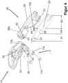
- the Figure 4 is an exploded view of the clamping device 1, consisting of the clamping element 10 and the clamping lever 20 and a clamping lever housing 26.
- the clamping element 10 is frame-shaped and includes an opening 52 through which an axle 30 can be inserted, forming part of the pivot joint D1 in which the clamping element 10 is rotatably connected to the clamping lever 20.
- the axle 30 can, for example, be a rivet that simultaneously connects the clamping element 10 to the clamping lever 20 in a captive manner.
- the clamping element 10 further comprises the contact device 11, which in the exemplary embodiment comprises a contact device axis 11b and a contact device support 11a.
- the contact device axis 11b is inserted through the opening 54 and then through the contact device support 11a, so that the contact device support 11a is arranged between the two at least partially free ends of the clamping element arms 10a, 10b.
- the stamped part 21 is divided into three sections A1, A2, and A3. The same applies, mutatis mutandis, to the mold plates 24, 25 and the clamping lever housing 26.
- the first section A1 comprises the receptacle 52 and forms an end of the stamped part 21 facing away from the ski boot, which can be connected or is connected to the clamping element 10 in the pivot joint D1. Near its free end, the section A1 has an upwardly projecting nose that forms a first stop 29a for the clamping lever housing 26.
- the second section A2 comprises the recess 28 and, in this embodiment, has a step on its upper side facing away from the base 103, which step forms a second stop 29b for the clamping lever housing 26.
- the third section A3 comprises the receptacle 53, the clamping lever head 22 and the clamping lever mouth 23 with the tongue 27.
- the Figure 4 a clamping lever housing 26, which comprises the two mold plates 24, 25, wherein the two mold plates 24, 25 are connected to one another in a connecting region 26a and form a type of sleeve for the stamped part 21, which partially surrounds the stamped part 21 on the sides and on its upper side facing away from the base 103.
- the connecting region 26a is designed such that its underside facing the base 103, with the first stop 29a and the second stop 29b, positively secures the clamping lever housing 26 at least in the lever longitudinal direction HL.
- Further connections of the clamping lever housing 26 to the stamped part 21 can be formed by the rotation axes D1, D2, or the axes 30 of these rotary joints D1, D2, which extend through the lever arm 20 or engage in the lever arm.
Landscapes
- Footwear And Its Accessory, Manufacturing Method And Apparatuses (AREA)
Description
- Die Erfindung betrifft einen Vorderbacken für eine Tourenskibindung, der eine Spannvorrichtung zum Festhalten eines Skischuhs in der Tourenskibindung aufweist, wobei die Spannvorrichtung einen Spannhebel umfasst, der zumindest teilweise ein aus einer Materialplatte ausgestanztes Stanzteil ist.
- Tourenskibindungen werden neben einer Abfahrt mit einem Ski auch primär dazu genutzt, mit dem Ski Hänge aufzusteigen. Neben dem Gewicht der Tourenskibindung ist auch der Preis ein Faktor, der die Kaufentscheidung des Kunden beeinflusst. Dabei kann ein Einsparpotential bei den Herstellungskosten zum Beispiel dadurch realisiert werden, dass die Herstellungszeit von Einzelteilen der Tourenskibindung reduziert wird. Diese Zeitersparnis kann beispielsweise dadurch realisiert werden, dass ein als Standard hingenommenes Herstellungsverfahren durch ein anderes, kostengünstigeres, einfacheres und/oder schnelleres Herstellungsverfahren ersetzt wird. Das heißt, dem Hersteller stellt sich die Aufgabe, bei jedem Herstellungsschritt jedes Tourenskibindungsteils die anfallenden Kosten zu überprüfen und nach kostengünstigeren Wegen für die Herstellung zu suchen.
- Diese Aufgabe wird durch den Gegenstand des Anspruchs 1 gelöst. Vorteilhafte Weiterbildungen sind in den von Anspruch 1 abhängigen Ansprüchen beschrieben.
- Einen gattungsgemäßen Vorderbacken weist beispielsweise die Tourenskibindung "Plum R150" auf (URL: https:l/www.fixation-plum.com/de/our-bindings/1210-race-150.html).
- Gegenstand der Erfindung ist ein Vorderbacken für eine Tourenskibindung, umfassend eine Basis und eine Lageranordnung, welche dafür eingerichtet ist, einen Skischuh um eine quer zu einer Skibindungslängsachse verlaufende Skiquerachse verschwenkbar zu halten, so dass der Skischuh bewegbar zwischen einer ersten Schwenkstellung, in der ein Fersenabschnitt des Skischuhs an den Ski angenähert ist, und einer zweiten Schwenkstellung, in der der Fersenabschnitt des Skischuhs von dem Ski entfernt ist, wobei der Vorderbacken eine Spannvorrichtung aufweist, mit welcher die Lageranordnung so verriegelbar ist, dass ein Verschwenken des Skischuhs möglich ist, ein Lösen des Skischuhs von der Lageranordnung jedoch auch bei Ausübung einer Sturzauslösekraft verhindert ist, wobei die Spannvorrichtung ein Spannelement und einen Spannhebel umfasst, wobei der Spannhebel in einem Drehgelenk mit der Basis verbindbar ist. Der Spannhebel weist in Hebellängsrichtung ein freies Ende auf, das einen Spannhebelkopf mit einem Spannhebelmaul umfasst. Das Spannhebelmaul ist hergerichtet, mit einer Mechanik des Vorderbackens zu koppeln, wobei die Mechanik die Lageranordnung des Vorderbackens spannt und entspannt.
- Nach der Erfindung ist der Spannhebel oder zumindest ein Teil des Spannhebels aus einer Materialplatte als Stanzteil ausgestanzt. Dabei kann das Stanzteil einlagig sein, oder es kann aus mehreren Schichten aufgebaut sein, von denen jede Schicht als Stanzteil hergestellt wurde. Zwei oder mehr Schichten können im Abschluss an das Stanzen zu dem genannten Teil des Spannhebels gefügt werden.
- Die Tourenskibindung umfasst neben dem Vorderbacken auch einen Hinterbacken, in dem der Skischuh während der Abfahrt an einem hinteren Ende oder Fersenende gehalten wird. Der Hinterbacken kann relativ zum Ski beispielsweise linear bewegt oder um eine Achse, die im Wesentlichen senkrecht zu einer Skioberfläche nach oben gerichtet ist, verschwenkt werden, um die Tourenskibindung aus dem Abfahrtsmodus in den Tourenmodus zu überführen. Bei dem Hinterbacken kann es sich um einen bekannten Hinterbacken zum Beispiel mit einem Automaten handeln, der auf eine Oberfläche eines hinteren Endes der Skischuhsohle drückt, oder einen Hinterbacken mit wenigstens einem Eingriffselement, das in wenigstens ein Gegeneingriffselement, das in der Skischuhsohle im Bereich des Fersenendes gebildet ist, eingreift, oder einen anderen bekannten Hinterbacken. Der Hinterbacken kann im Tourenmodus der Tourenskibindung wenigstens eine Aufstiegshilfe bilden und/oder wenigstens eine relativ zum Hinterbacken verstellbare Aufstiegshilfe umfassen.
- Bei der Lageranordnung kann es sich um zwei sich bezüglich einer Skimittellängsachse gegenüberliegende Eingriffselemente handeln, die jeweils im Bereich eines ersten freien Endes eines ersten respektive zweiten Arms verbunden sind, wobei ein zweites freie Ende des ersten und des zweiten Arms schwenkbar in dem Vorderbacken gehalten wird. Der erste und der zweite Arm können mittels der Mechanik synchron in eine erste Position und in eine zweite Position verschwenkt werden. In der ersten Position weisen die beiden Eingriffselemente einen maximalen Abstand zueinander auf, so dass ein Nutzer mit einem Skischuh in den Vorderbacken einsteigen kann. In der zweiten Position weisen die beiden Eingriffselemente einen Abstand zueinander auf, der kleiner ist als der maximale Abstand der ersten Position. Die beiden Eingriffselemente definieren in der zweiten Position eine Schwenkachse für die Schwenkbewegung des Skischuhs. In der zweiten Position können die Eingriffselemente in Öffnungen eingreifen, die in einer Skischuhsohle des Skischuhs gebildet sind und den Skischuh dadurch am vorderen Ende oder Zehenende im Tourenmodus mit dem Ski verbinden. Skibindungen mit derartige Vorderbacken werden auch als Pin-Bindungen bezeichnet.
- Die meisten Tourenskibindungen weisen Spannvorrichtungen auf, um die Lageranordnung bei einem Aufstieg mit dem Ski zu verriegeln, sodass ein Verschwenken des Skischuhs möglich ist, ein Lösen des Skischuhs von der Lageranordnung jedoch auch bei Ausübung einer Sturzauslösekraft verhindert ist. Der unverriegelte Zustand der Lageranordnung ist bei einer Abfahrt mit dem Ski gewünscht, sodass sich die Tourenskibindung bei genügend hoher Sturzauslösekraft öffnen, den Skischuh freigeben und damit Verletzungen vermeiden kann.
- Das Lösen des Skischuhs aus der Tourenskibindung bei einem Sturz, bei einer Seitenbelastung oder Belastung in oder gegen die Fahrtrichtung über einem einstellbaren Grenzwert, kann durch den Vorderbacken und/oder durch den Hinterbacken erfolgen.
- Das Material der Materialplatte oder der Materialplatten kann ein Kunststoff, insbesondere ein verstärkter Kunststoff, ein Stahl, ein Aluminium, ein Magnesium oder eine Legierung, die wenigstens eines dieser Materiale umfasst, sein. Alternative Materialien sind möglich, solange sie die notwendige Festigkeit bei den zu erwartenden Umweltbedingungen für eine Tourenskibindung haben. Das heißt, dass bei einem Aufbau aus mehreren Schichten, das genannte Teil des Spannhebels aus Schichten eines Materials oder aus Schichten unterschiedlicher Materialien gebildet sein kann. Werden mehrere Schichten miteinander verbunden, müssen nicht alle Schichten vollflächig sein, wodurch Material und Gewicht eingespart werden kann. Zum Beispiel kann bei einem mehrschichtigen Aufbau des Spannhebels wenigstens eine Schicht aus einem Vollmaterial, insbesondere einem Metall, bestehen, während wenigstens eine der weiteren Schichten, zum Beispiel aus Kunststoff, eine Skelettstruktur aufweisen kann, mit bevorzugt einer geschlossenen Außenseite, die eine seitliche Oberfläche des Spannhebels bilden kann. Vorteilhaft kann es beispielsweise auch sein, ein korrosionsanfälliges Material zwischen zwei Schichten anzuordnen, bei den für die Lebenszeit des Produkts keine Korrosionsprobleme zu erwarten sind.
- Als Herstellungstechnik für die Herstellung des Spannhebels, insbesondere des wenigstens einen Vollmaterialteils, wird das Ausstanzen aus der Materialplatte mittels einer Stanzvorrichtung oder Stanze gewählt.
- Der Spannhebel kann zusätzlich zu der Verbindung in dem Drehgelenk mit der Basis in einem weiteren Drehgelenk mit dem Spannelement insbesondere verliersicher verbindbar oder verbunden sein. Dabei kann ein Niet eine Drehachse des weiteren Drehgelenks bilden. Der Niet kann den Spannhebel in dem weiteren Drehgelenk dreh- oder schwenkbar und verliersicher in dem Spannelement halten.
- Der Spannhebel kann länglich sein und weist in Spannhebel- oder Hebellängsrichtung das freie Ende auf, das den Spannhebelkopf mit dem Spannhebelmaul umfasst. Eine Spannhebellängsachse kann zumindest in einer Schwenkposition, eventuell in einer nur theoretisch erreichbaren Schwenkposition des Spannhebels parallel zu der Skibindungslängsachse verlaufen.
- Das Spannhebelmaul ist hergerichtet, mit einer Mechanik des Vorderbackens zu koppeln, oder in diese Mechanik einzugreifen. Eine Schwenkbewegung des Spannhebels kann bevorzugt auf die Mechanik übertragen werden. Die Mechanik kann dafür vorgesehen sein, die Lageranordnung des Vorderbackens zu spannen, so dass der Skischuh in der Lageranordnung gehalten wird, und zu entspannen, um den Skischuh aus der Lageranordnung frei zu geben.
- Der Spannhebel kann allein durch das wenigstens eine Stanzteil gebildet sein. Alternativ kann der Spannhebel in Sandwichbauweise aufgebaut sein, wobei das Stanzteil zwischen wenigstens einer ersten Formplatte und wenigstens einer zweiten Formplatte angeordnet ist, so dass eine der Formplatten eine linke Außenseite und eine andere der Formplatten eine rechte Außenseite des Spannhebels bildet. Dabei können die erste Formplatte und die zweite Formplatte separate Formplatten sein, die einzeln mit dem Stanzteil gefügt werden. Alternativ können die erste Formplatte und die zweite Formplatte miteinander verbunden, bevorzugt in einem Stück urgeformt sein und ein Spannhebelgehäuse bilden, das das Stanzteil zumindest teilweise umgreift.
- Die erste Formplatte und die zweite Formplatte, respektive das Spannhebelgehäuse, können aus einem Kunststoff, bevorzugt in einem Kunststoffspritz- oder Tiefziehverfahren, hergestellt sein. Sie können dreidimensional ausgebildet sein, zum Beispiel als Hohlkörper mit einer formenden Verstärkungsstruktur, und eine bedruckbare Oberfläche haben, so dass sie an ein beliebiges Design angepasst werden können. Die Formplatten können auch aus einem durchsichtigen oder transparenten Material oder Kunststoff gebildet sein, der zum Beispiel an seiner Innenseite bedruckbar ist. Schließlich können die Formplatten Abschnitte unterschiedlicher Materialen haben, zum Beispiel in einem Zwei- oder Mehrkomponentenkunststoffspritzverfahren hergestellt sein oder Einlegeteile umfassen, die mit Kunststoff umspritzt sind.
- Bevorzugt sind die erste Formplatte und die zweite Formplatte mit dem Stanzteil gefügt, bevorzugt form- und/oder stoffschlüssig gefügt. Unter Stoffschluss kann beispielsweise die Verbindung mittels eines Klebstoffes verstanden werden. Eine Außenumfangsform der Auflagefläche der ersten und zweiten Formplatte, die an dem Stanzteil anliegt, kann im Wesentlichen der Außenumfangsform des Stanzteils entsprechen.
- Die form- und/oder stoffschlüssigen Verbindung verbindet das Stanzteil mit der ersten Formplatte und der zweiten Formplatter bevorzugt elastisch, so dass zum Beispiel eine temperaturabhängige, unterschiedliche Ausdehnung zwischen dem Stanzteil durch die elastische Verbindung ausgeglichen werden kann. Bevorzugt ist es, wenn das Material des Stanzteils und das Material der ersten und zweiten Formplatte, respektive des Spannhebelgehäuses, in einem Temperaturbereich zwischen -30°C bis + 40°C, bevorzugt zwischen -25°C und + 35°C und besonders bevorzugt -20°C und +30°C einen ähnlichen, bevorzugt im Wesentlichen gleichen, Längenausdehnungskoeffizienten hat.
- Vorzugsweise weisen die erste Formplatte und die zweite Formplatte eine Längserstreckung auf, die kleiner ist, als eine Längserstreckung des Stanzteils, so dass das Spannhebelmaul, respektive eine Zunge des Spannhebelmauls zumindest teilweise über die erste und die zweite Formplatte in Richtung auf die Mechanik zum Spannen und Entspannen der Spannvorrichtung vorsteht.
- Das Stanzteil ist mit dem Spannhebelgehäuse bevorzugt formschlüssig verbunden. Das Stanzteil kann insbesondere mittels einer oder mehreren Nietverbindungen mit dem Spannhebelgehäuse verbunden und an dem Spannhebelgehäuse gesichert sein. Bei dem Niet kann es sich um einen Teil des ersten Drehgelenks und/oder des zweiten Drehgelenks handeln. Zusätzlich kann das Stanzteil mit den Formteilen oder dem Spannhebelgehäuse verklebt sein. Alternativ kann das Spannhebelgehäuse mit dem Stanzteil über einen Schraubenkörper und/oder mittels eines Adhäsivs verbunden sein. Schließlich kann eines von Stanzteil und Spannhebelgehäuse ein Eingriffselement umfassen, das in ein Gegeneingriffselement von dem anderen von Stanzteil und Spannhebelgehäuse eingreift. Das Gegeneingriffselement kann beispielsweise ein Schlitz oder eine Durchgangsöffnung in dem Stanzteil sein, das bereits beim Stanzenmit erzeugt wird, so dass kein weiterer Bearbeitungsschritt nötig ist. Das Gegeneingriffselement kann aber auch in einem anschließenden Bearbeitungsschritt erzeugt werden. Entsprechend kann das Eingriffselement von dem Spannhebelgehäuse gebildet werden.
- Das Spannelement kann in einem Drehgelenk mit dem Spannhebel bevorzugt verliersicher verbunden und in dem Drehgelenk relativ zu dem Spannhebel verschwenkbar sein. Dabei kann der Spannhebel zumindest in einer Schwenkposition mit einem vom Spannhebelkopf abgewandten Ende innerhalb des Spannelements liegen, soll heißen, zumindest teilweise vom Spannelement umgeben sein.
- Wie bereits beschrieben, kann der Spannhebel in einem weiteren Drehgelenk mit der Basis verbunden und relativ zur Basis verschwenkbar sein. Dabei kann das Drehgelenk, in dem das Spannelement mit dem Spannhebel verbunden ist, in Skilängsrichtung gesehen nach oder hinter dem weiteren Drehgelenk, das heißt, näher an der Skispitze, angeordnet sein. Die Basis kann dabei geeignet sein, direkt mit einem Ski verbunden zu werden oder aber über ein oder weitere Zwischenelemente mit dem Ski verbunden zu werden.
- Das Spannelement kann eine Kontakteinrichtung aufweisen, welche bei einem Verschwenken des Spannelements um das Drehgelenk, welches das Spannelement mit dem Spannhebel verbindet, in und außer Kontakt mit einer Kontaktfläche der Basis gebracht wird. Die Kontaktfläche dient zum Beispiel als Anschlag für die Kontakteinrichtung des Spannelements und begrenzt in der verrasteten Stellung, d.h. bei Kontakt zwischen Kontakteinrichtung und Kontaktfläche, die Bewegung des Spannhebels. Über die Kopplung des Spannhebels über eine Mechanik mit der Lageranordnung ist die Lageranordnung verriegelt, sodass sich ein im Vorderbacken befindlicher Skischuh auch bei Ausübung einer Sturzauslösekraft nicht von der Lageranordnung lösen kann. Dieser Zustand ist bei Aufstieg mit der Tourenskibindung gewünscht und vorteilhaft.
- Das Stanzteil kann wenigstens drei klar voneinander abgegrenzte Abschnitte aufweisen: einen ersten Abschnitt, der eine Aufnahme respektive eine Öffnung für eine Gelenkachse des Drehgelenks, welches den Spannhebel mit dem Spannelement verbindet, umfasst, einen sich an den ersten Abschnitt anschließenden zweiten Abschnitt, der so gestaltet sein kann, dass er eine erforderliche Beweglichkeit des Spannhebels in dem Vorderbacken ermöglicht und/oder in wenigstens einer Schwenkposition der Kontakteinrichtung eine Verrastung für die Kontakteinrichtung bilden kann, und einen an den zweiten Abschnitt anschließenden dritten Abschnitt, der eine Aufnahme respektive eine Öffnung für die Gelenkachse des Drehgelenks, welches das Stanzteil bevorzugt mit der Basis verbindet, und den Spannhebelkopf mit dem Spannhebelmaul umfasst. Die Formplatten oder das Spannhebelgehäuse können ebenfalls diese Abschnitte aufweisen, mit der Ausnahme, dass der Spannhebelkopf mit dem Spannhebelmaul nicht oder zumindest nur teilweise von den Formplatten oder dem Spannhebelgehäuse überdeckt wird.
- Mit anderen Worten können die erste und/oder die zweite Formplatte oder das Spannhebelgehäuse wenigstens drei Bereiche aufweisen, einen ersten Bereich, der eine Aufnahme für das Drehgelenk, welches den Spannhebel mit dem Spannelement verbindet, umfasst, einen sich an den ersten Bereich anschließenden zweiten Bereich, der so gestaltet ist, dass er in einer Schwenkposition der Kontakteinrichtung eine Verrastung für die Kontakteinrichtung bilden kann, und einen an den zweiten Bereich anschließenden dritten Bereich, der eine Aufnahme für ein Drehgelenk, welches das Stanzteil bevorzugt mit der Basis verbindet, umfasst. Dabei umfasst das Stanzteil den Spannhebelkopf mit dem Spannhebelmaul, und wenigstens eine Zunge oder ein Teil der Zunge des Spannhebelmauls kann in Längsrichtung des Vorderbackens über ein Ende der ersten und der zweiten Formplatte vorstehen.
- In Folgenden wird der Gegenstand der Anmeldung anhand eines Ausführungsbeispiels weiter erläutert, ohne dass die Erfindung dadurch auf das gezeigte Ausführungsbeispiel beschränkt werden soll. Technische Merkmale, die erfindungswesentlich sind und nur den Figuren zu entnehmen sind, zählen zum Umfang der Offenbarung und können den Gegenstand vorteilhaft weiterbilden. Die Figuren zeigen im Einzelnen:
- Figur 1:
- Perspektivische Ansicht eines Vorderbackens;
- Figur 2:
- Schnitt entlang einer Längsachse durch den Vorderbacken der
Figur 1 ; - Figur 3:
- vier Detaildarstellungen der Spannvorrichtung des Vorderbackens der
Figur 1 ; - Figur 4:
- Explosionszeichnung des Vorderbackens der
Figur 1 mit Spannhebelgehäuse. - Die
Figur 1 zeigt einen Vorderbacken 100 für eine Tourenskibindung. Der Vorderbacken 100 umfasst eine Basis 103, über die der Vorderbacken 100 mit einem nicht gezeigten Ski verbunden werden kann. Des Weiteren umfasst der Vorderbacken 100 eine Lageranordnung 101, die im Ausführungsbeispiel aus zwei Pins besteht, die dafür vorgesehen sind, in Aufnahmen eines nicht gezeigten Skischuhs einzugreifen. Die Lageranordnung 101 oder die Pins verbinden in einer ersten Position den Vorderbacken 100 fest mit dem Skischuh und bilden eine Achse, die in eine Querrichtung Q zu einer Längsachse L des Vorderbackens 100 verläuft. Der Skischuh kann um die Achse aus einer ersten Position, in der die Skischuhsohle im Wesentlichen parallel zu einer Oberseite des Skis verläuft und der Fersenabschnitt des Skischuhs an den Ski angenähert ist, in eine zweite Position, in der die Skischuhsohle einen spitzen Winkel mit der Oberseite des Skis bildet, der Fersenabschnitt des Skischuhs vom Ski entfernt ist, verschwenkt werden. - Um die Lageranordnung von der ersten Position in die zweite Position zu bewegen und bevorzugt in der jeweiligen Position zu sichern, umfasst der Vorderbacken 100 eine Spannvorrichtung 1 mit einem Spannelement 10 und einem Spannhebel 20. Das Spannelement 10 und der Spannhebel 20 sind in einem Drehgelenk D1 miteinander verbunden. Der Spannhebel 20 ist in einem Drehgelenk D2 mit der Basis 103 verbunden. Der Spannhebel 20 wirkt auf eine Mechanik 102 ein, die mit der Lageranordnung 101, respektive den Pins, verbunden ist, um diese in die erste Position zu bewegen, in der die Lageranordnung 101 mit dem Skischuh verbunden ist, und aus der ersten Position in eine zweite Position, in der der Skischuh aus dem Vorderbacken 100 herausgenommen werden kann.
- Der Spannhebel 20 besteht aus mehreren Teilen, die miteinander gefügt sind. Im Ausführungsbeispiel besteht der Spannhebel 20 aus einem Mittelteil oder einer Seele, die aus einem Plattenmaterial ausgestanzt ist, und daher auch als Stanzteil 21 bezeichnet wird.
- Das Stanzteil 21 ist bevorzugt aus einem Metall, beispielsweise aus Aluminium, Stahl, Magnesium, einem anderen geeigneten Metall oder aus einer Legierung, die wenigstens eines der genannten Metalle umfasst, gebildet. Das Mittelteil kann aber auch aus mehr als einem Stanzteil 21 bestehen, die miteinander gefügt werden, um das Mittelteil zu bilden. Besteht das Mittelteil aus mehr als einem Stanzteil 21, so können die Stanzteile 21 aus unterschiedlichen Materialen gebildet sein, zum Beispiel aus unterschiedlichen Metallen oder Metalllegierungen.
- Mit dem Stanzteil 21 sind zwei Formplatten 24, 25 gefügt, die eine rechte und eine linke Seite des Spannhebels 20 bilden. Die Formplatten 24, 25 können ebenfalls aus Metall gebildet sein, bevorzugt handelt es sich aber um Kunststoffteile, die zum Beispiel in einem Spritzguss-, einem Tiefzieh- oder einem anderen geeigneten Herstellungsverfahren hergestellt werden. Als geeignete Kunststoff können, ohne Anspruch auf Vollständigkeit der Aufzählung, zum Beispiel Polypropylen, Polyethylen, Polystyrol, PMMA, ABS oder ASA/ABS verwendet werden.
- Da bei der Entwicklung neuer Skibindungen das Gewicht immer ein Faktor ist, der mit berücksichtig wird, kann zum Gewichteinsparen, das Stanzteil 21 zum Beispiel einen Längsschlitz im Zentralbereich aufweisen, der beispielsweise bei der Stanzung gleich mit eingebracht wird, da hierdurch kein zusätzlicher Zeitaufwand nötig ist, anders als beispielsweise beim Schneiden. Durchbrüche an anderer Stelle sind denkbar und ihre Eignung vom Fachmann durch Versuche leicht zu überprüfen.
- Die Formplatten 24, 25 können schalenförmig, teilweise schalenförmig oder aus Vollmaterial gebildet sein. Schalenförmige, respektive teilschalenförmige Formplatten 24, 25 können integrierte Verstärkungsstrukturen, wie Verstärkungsrippen, Verstärkungsnoppen, etc. aufweisen, um ein Kollabieren oder Eindrücken der Schale bei Krafteinwirkung von der Seite zu verhindern. Schließlich können die Formplatten 24, 25 bereichsweise aus unterschiedlichen Materialen bestehen, zum Beispiel aus unterschiedlichen Kunststoffen oder teilweise aus Naturstoffen, wie kompostierbaren Naturfasern, um ein weiteres Argument für die Bewerbung zu haben.
- Die
Figur 2 zeigt einen Schnitt durch den Vorderbacken 100 entlang einer Skibindungslängsachse L. Das Stanzteil 21 ist gut zu sehen. Das Stanzteil 21 weist einen Durchbruch oder eine Aufnahme 52 auf, die Teil des Drehgelenks D1 ist oder das Drehgelenk D1 zumindest aufnimmt, in dem des Spannelement 10 drehbeweglich mit dem Spannhebel 20 verbunden werden kann. Weiterhin ist ein Durchbruch oder eine Ausnehmung 53 in dem Stanzteil 21 gebildet, die Teil des Drehgelenks D2 bildet oder das Drehgelenk D2 zumindest aufnimmt, in dem der Spannhebel 20 drehbar mit der Basis 103 verbunden werden kann. - Das Stanzteil 21 umfasst an seinem der Mechanik 102 zugewandten Ende einen Spannhebelkopf 22 mit einem Spannhebelmaul 23. Das Spannhebelmaul 23 koppelt mit der Mechanik 102, so dass eine Bewegung des Spannhebels 20 direkt auf die Mechanik 102 übertragen wird. In der
Figur 2 drückt der Spannhebel 20 die Mechanik 102 nach unten nahe an die Basis 103, wodurch die Kontakteinrichtung 11, respektive die Pins, an den nichtgezeigten Skischuh angedrückt respektive in Ausnehmungen in der Skischuhsohle hineingedrückt werden. - Das Spannelement 10 umfasst eine Kontakteinrichtung 11, die mit einer Kontaktfläche 104 zusammenwirkt, und eine Abstützung und Sicherung für das Spannelement 10 zumindest in der ersten Position und in der zweiten Position bildet. Die Kontaktfläche 104 ist mit der Basis 103 verbunden oder kann Teil der Basis 103 sein, zum Beispiel mit der Basis 103 in einem Stück urgeformt sein. Der Spannhebel 20 weist in einem in Hebellängsrichtung HL gesehen mittleren Bereich an seiner dem Ski zugewandten Seite eine Ausnehmung 28 auf, welche in einer Schwenkposition des Spannelements 10 eine Verrastung für die Kontakteinrichtung 11 und damit auch für das Spannelement 10 bildet. Die Ausnehmung 28 kann aber auch nur dem Aufbau des Vorderbackens geschuldet sein und die erforderliche Beweglichkeit des Spannhebels 20 im Vorderbacken ermöglichen.
- Die
Figur 3 zeigt vier Detaildarstellungen der Spannvorrichtung 1 bestehend aus der Spannvorrichtung 10 und dem Spannhebel 20 (Abb. a), einen Längsschnitt durch die Spannvorrichtung 1 (Abb. b), den Spannhebel 20 (Abb. c) und einen Längsschnitt durch den Spannhebel 20 (Abb. d). - Abb. a) zeigt ein Ausführungsbeispiel der Spannvorrichtung 1 mit einem Spannelement 10 und einem Spannhebel 20. Das Spannelement 10 ist rahmenförmig ausgebildet und umfasst einen Teil des Drehgelenks D1 und die Kontakteinrichtung 11, die in der Abbildung in der Ausnehmung 28 des Spannhebels 20 liegt.
- Der Spannhebel 20 umfasst das Stanzteil 21 mit dem Spannhebelkopf 22 mit dem Spannhebelmaul 23 und einer Zunge 27, die eine Verlängerung eines der Basis 103 zugewandten unteren Teils des Spannhebelmauls 23 ist. Ferner umfasst der Spannhebel 20 die Formplatte 24 und die Formplatte 25, die die Außenseiten des Spannhebels 20 bilden und mit dem Stanzteil 21 gefügt sind. Dabei können die Formplatten 24, 25 mit dem Stanzteil 21 lösbar gefügt sein, so dass sie ausgetauscht werden können, oder fest gefügt sein, so dass sie zerstörungsfrei nicht von dem Stanzteil 21 getrennt werden können.
- Abb. b) zeigt einen Längsschnitt durch die Spannvorrichtung der Abb. a). In dem Stanzteil 21 sind die Ausnehmung 52 gebildet, in der das Spannelement 10 und der Spannhebel 20 in dem Drehgelenk D1 miteinander verbunden sind, und die Ausnehmung 53, in der der Spannhebel 20 mit der Basis 103 in dem Drehgelenk D2 verbunden werden kann.
- Abb. c) zeigt nur noch den Spannhebel 20, mit dem Stanzteil 21 als Mittelteil und den beiden Formplatten 24, 25, die an einer rechten, respektive linken Längsseite des Stanzteils 21, die senkrecht zu einer Hebellängsachse HL des Stanzteils 21 stehen, mit dem Stanzteil 21 gefügt sind. In der Abb. c) ist gut zu erkennen, dass das Stanzteil 21 an einem seiner Enden in Hebellängsrichtung HL einen Spannhebelkopf 22 und ein Spannhebelmaul 23 ausbildet und das Spannhebelmaul 23 an seiner der Basis 103 zugewandten Seite eine Zunge 27 umfasst. Die Formplatten 24, 25 überdecken im Ausführungsbeispiel die gesamte Seitenfläche des Stanzteils 21 mit Ausnahme der Zunge 27. Das heißt, eine Außenumfangsform der Formplatten 24, 25 entspricht einer Außenumfangsform des Stanzteils 21, jedoch ohne die Zunge 27. Die Zunge 27 steht im Ausführungsbeispiel nach vorne über die Formplatten 24, 25 vor.
- Abb. d) zeigt einen Längsschnitt durch den Spannhebel der Abb. c). In der Abb. d) ist zu erkennen, dass es sich bei den Ausnehmungen 52 und 53 für die Drehgelenke D1 und D2 um Durchgangsöffnungen handelt.
- Die
Figur 4 ist eine Explosionszeichnung der Spannvorrichtung 1, bestehend aus dem Spannelement 10 und dem Spannhebel 20 und einem Spannhebelgehäuse 26. - Das Spannelement 10 ist rahmenförmig gebildet und umfasst eine Öffnung 52, durch die eine Achse 30 gesteckt werden kann, die einen Teil des Drehgelenks D1 bildet, in dem das Spannelement 10 mit dem Spannhebel 20 drehbar verbunden ist. Bei der Achse 30 kann es sich beispielweise um einen Niet handeln, der gleichzeitig das Spannelement 10 mit dem Spannhebel 20 verliersicher verbindet.
- Das Spannelement 10 umfasst ferner die Kontakteinrichtung 11, die im Ausführungsbeispiel eine Kontakteinrichtungsachse 11b und eine Kontakteinrichtungsauflage 11a umfasst. Die Kontakteinrichtungsachse 11b wird durch die Öffnung 54 und anschließend durch die Kontakteinrichtungsauflage 11a gesteckt, so dass die Kontakteinrichtungsauflage 11a zwischen den beiden zumindest teilweise freien Enden der Spannelementarme 10a, 10b angeordnet ist.
- Das Stanzteil 21 ist in drei Abschnitte A1, A2, A3 unterteilt. Gleiches gilt mutatis mutandis für die Formplatten 24, 25 und das Spannhebelgehäuse 26.
- Der erste Abschnitt A1 umfasst die Aufnahme 52 und bildet ein von dem Skischuh abgewandtes Ende des Stanzteils 21, welches in dem Drehgelenkt D1 mit dem Spannelement 10 verbunden werden kann oder verbunden ist. Der Abschnitt A1 weist nahe seinem freien Ende eine nach oben vorstehende Nase auf, die einen ersten Anschlag 29a für das Spannhebelgehäuse 26 bildet.
- Der zweite Abschnitt A2 umfasst die Ausnehmung 28 und weist in diesem Ausführungsbeispiel an seiner von der Basis 103 abgewandten Oberseite eine Stufe auf, die einen zweiten Anschlag 29b für das Spannhebelgehäuse 26 bildet.
- Der dritte Abschnitt A3 umfasst die Aufnahme 53, den Spannhebelkopf 22 und das Spannhebelmaul 23 mit der Zunge 27.
- Schließlich zeigt die
Figur 4 eine Spannhebelgehäuse 26, das die beiden Formplatten 24, 25 umfasst, wobei die beiden Formplatten 24, 25 in einem Verbindungsbereich 26a miteinander verbunden sind, und eine Art Hülle für das Stanzteil 21 bilden, die das Stanzteil 21 teilweise an den Seiten und an seiner von der Basis 103 abgewandten Oberseite umfasst. Der Verbindungsbereich 26a ist im Ausführungsbeispiel so ausgebildet, dass seine der Basis 103 zugewandte Unterseite mit dem ersten Anschlag 29a und dem zweiten Anschlag 29b das Spannhebelgehäuse 26 zumindest in die Hebellängsrichtung HL formschlüssig festlegt. Weitere Verbindungen des Spannhebelgehäuses 26 mit dem Stanzteil 21 können die Drehachsen D1, D2, respektive die den Hebelarm 20 durchgreifenden oder in den Hebelarm eingreifenden Achsen 30 dieser Drehgelenke D1, D2 bilden. -
- 1
- Spannvorrichtung
- 10
- Spannelement
- 10a
- Spannelementarm
- 10b
- Spannelementarm
- 11
- Kontakteinrichtung
- 11a
- Kontakteinrichtungsauflage
- 11b
- Kontakteinrichtungsachse
- 20
- Spannhebel
- 21
- Stanzteil
- 22
- Spannhebelkopf
- 23
- Spannhebelmaul
- 24
- Formplatte
- 25
- Formplatte
- 26
- Spannhebelgehäuse
- 26a
- Verbindungsbereich
- 27
- Zunge
- 28
- Ausnehmung
- 29a
- Anschlag
- 29b
- Anschlag
- 30
- Achse
- 52
- Aufnahme
- 53
- Aufnahme
- 54
- Aufnahme
- 100
- Vorderbacken
- 101
- Lageranordnung, Pin
- 102
- Mechanik
- 103
- Basis
- 104
- Kontaktfläche
- A1
- Abschnitt
- A2
- Abschnitt
- A3
- Abschnitt
- D1
- Drehgelenk
- D2
- Drehgelenk
- L
- Skibindungslängsachse
- Q
- Skibindungsquerachse
- HL
- Hebellängsrichtung
- SL
- Skilängsrichtung
Claims (16)
- Vorderbacken (100) für eine Tourenskibindung,1.1 umfassend eine Basis (103) und eine Lageranordnung (101), welche dafür eingerichtet ist, einen Skischuh um eine quer zu einer Skibindungslängsachse (L) verlaufende Skiquerachse (Q) verschwenkbar zu halten, so dass der Skischuh bewegbar ist zwischen einer ersten Schwenkstellung, in der ein Fersenabschnitt des Skischuhs an den Ski angenähert ist, und einer zweiten Schwenkstellung, in der der Fersenabschnitt des Skischuhs von dem Ski entfernt ist, wobei1.2 der Vorderbacken (100) eine Spannvorrichtung (1) aufweist, mit welcher die Lageranordnung (101) so verriegelbar ist, dass ein Verschwenken des Skischuhs möglich ist, ein Lösen des Skischuhs von der Lageranordnung (101)jedoch auch bei Ausübung einer Sturzauslösekraft verhindert ist,1.3 die Spannvorrichtung (1) ein Spannelement (10) und einen Spannhebel (20) umfasst,1.4 der Spannhebel (20) in einem Drehgelenk (D2) mit der Basis (103) verbindbar ist,1.5 der Spannhebel (20) in Hebellängsrichtung (HL) ein freies Ende aufweist, das einen Spannhebelkopf (22) mit einem Spannhebelmaul (23) umfasst, und1.6 das Spannhebelmaul (23) hergerichtet ist, mit einer Mechanik (102) des Vorderbackens (100) zu koppeln, wobei die Mechanik (102) die Lageranordnung (101) des Vorderbackens (100) spannt und entspannt,
dadurch gekennzeichnet, dass1.7 der Spannhebel (20) oder zumindest ein Teil des Spannhebels (20) ein aus einer Materialplatte ausgestanztes Stanzteil (21) ist, das entlang einer Skibindungslängsachse (L) ausgerichtet ist und an einem der Mechanik (102) zugewandten Ende den Spannhebelkopf mit dem Spannhebelmaul aufweist. - Vorderbacken (100) für eine Tourenskibindung mit einer Spannvorrichtung (1) nach Anspruch 1, wobei das Material ein Kunststoff, ein Stahl, ein Aluminium, ein Magnesium oder eine Legierung, die wenigstens eines dieser Materialien umfasst, ist.
- Vorderbacken (100) für eine Tourenskibindung mit einer Spannvorrichtung (1) nach einem der vorhergehenden Ansprüche, wobei der Spannhebel (20) in einem weiteren Drehgelenk (D1) mit dem Spannelement (10) verbindbar ist.
- Vorderbacken (100) für eine Tourenskibindung mit einer Spannvorrichtung (1) nach einem der vorhergehenden Ansprüche, wobei das Stanzteil (21) entlang der Skibindungslängsachse (L) und/oder parallel zur Skibindungslängsachse (L) angeordnet ist.
- Vorderbacken (100) für eine Tourenskibindung mit einer Spannvorrichtung (1) nach einem der vorhergehenden Ansprüche, wobei der Spannhebel (20) in Sandwichbauweise aufgebaut ist, wobei das Stanzteil (21) zwischen einer ersten Formplatte (24, 25) und einer zweiten Formplatte (24, 25) angeordnet ist, so dass eine der Formplatten (24, 25) eine linke Außenseite und die andere der Formplatten (24, 25) eine rechte Außenseite des Spannhebels (20) bildet.
- Vorderbacken (100) für eine Tourenskibindung mit einer Spannvorrichtung (1) nach dem vorhergehenden Anspruch, wobei die erste Formplatte (24, 25) und die zweite Formplatte (24, 25) separate Formplatten (24, 25) sind, die einzeln mit dem Stanzteil (21) gefügt werden oder wobei die erste Formplatte (24, 25) und die zweite Formplatte (24, 25) miteinander verbunden, bevorzugt in einem Stück urgeformt sind, und ein Spannhebelgehäuse (26) bilden.
- Vorderbacken (100) für eine Tourenskibindung mit einer Spannvorrichtung (1) nach einem der zwei vorhergehenden Ansprüche, wobei die erste Formplatte (24, 25) und die zweite Formplatte (24, 25), respektive das Spannhebelgehäuse (26), aus Kunststoff, zum Beispiel in einem Kunststoffspritz- oder Tiefziehverfahren, hergestellt sind.
- Vorderbacken (100) für eine Tourenskibindung mit einer Spannvorrichtung (1) nach einem der drei vorhergehenden Ansprüche, wobei die erste Formplatte (24, 25) und die zweite Formplatte (24, 25), respektive das Spannhebelgehäuse (26), mit dem Stanzteil (21) gefügt sind, bevorzugt form- oder stoffschlüssig.
- Vorderbacken (100) für eine Tourenskibindung mit einer Spannvorrichtung (1) nach einem der vier vorhergehenden Ansprüche, wobei die erste Formplatte (24, 25) und die zweite Formplatte (24, 25) eine Längserstreckung aufweisen, die kleiner als eine Längserstreckung des Stanzteils (21) ist, so dass bevorzugt das Spannhebelmaul (23), respektive eine Zunge (27) des Spannhebelmauls (23), zumindest teilweise über die erste und die zweite Formplatte (24, 25) vorsteht.
- Vorderbacken (100) für eine Tourenskibindung mit einer Spannvorrichtung (1) nach einem der fünf vorhergehenden Ansprüche, wobei eine Außenumfangsform der Auflagefläche der ersten und zweiten Formplatte (24, 25), die an dem Stanzteil (21) anliegt, im Wesentlichen der Außenumfangsform des Stanzteils (21) entspricht.
- Vorderbacken (100) für eine Tourenskibindung mit einer Spannvorrichtung (1) nach einem der Ansprüche 5 bis 10, wobei eine stoffschlüssige und/oder eine formschlüssige Verbindung das Stanzteil (21) mit der ersten und zweiten Formplatte (24, 25), respektive dem Spannhebelgehäuse (26), elastisch verbindet, um unterschiedliche Ausdehnungen aufgrund von Wärme oder Kälte auszugleichen.
- Vorderbacken (100) für eine Tourenskibindung mit einer Spannvorrichtung (1) nach einem der sieben vorhergehenden Ansprüche, wobei das Material des Stanzteils (21) und das Material der ersten und zweiten Formplatte (24, 25), respektive des Spannhebelgehäuses (26), in einem Temperaturbereich zwischen -20°C und +30°C einen ähnlichen, bevorzugt im Wesentlichen gleichen, Längenausdehnungskoeffizienten hat.
- Vorderbacken (100) für eine Tourenskibindung mit einer Spannvorrichtung (1) nach einem der vorhergehenden Ansprüche, wobei das Spannelement (10) eine Kontakteinrichtung (11) aufweist, welche bei einem Verschwenken des Spannelements (10) um das Drehgelenk (D1) in und außer Kontakt mit einer Kontaktfläche (104) der Basis (103) bringbar ist.
- Vorderbacken (100) für eine Tourenskibindung mit einer Spannvorrichtung (1) nach dem vorhergehenden Anspruch, wobei der Schwenkhebel (20) wenigstens drei Abschnitte (A1, A2, A3) aufweist, einen ersten Abschnitt (A1), der eine Aufnahme (52) für eine Gelenkachse des Drehgelenks (D1) umfasst, einen sich an den ersten Abschnitt (A1) anschließenden zweiten Abschnitt (A2), der so gestaltet ist, dass er in einer Schwenkposition der Kontakteinrichtung (11) eine Verrastung für die Kontakteinrichtung (11) bilden kann, und einen an den zweiten Abschnitt (A2) anschließenden dritten Abschnitt (A3), der eine Aufnahme (53) für eine Gelenkachse des Drehgelenks (D2) und den Spannhebelkopf (22) mit dem Spannhebelmaul (23) umfasst.
- Vorderbacken (100) für eine Tourenskibindung mit einer Spannvorrichtung (1) nach einem der vorhergehenden Ansprüche, wobei das Stanzteil (21) einen Durchbruch oder eine Aufnahme (52) aufweist, die Teil des Drehgelenks (D1) ist oder das Drehgelenk (D1) zumindest aufnimmt, in dem des Spannelement (10) drehbeweglich mit dem Spannhebel (20) verbindbar ist.
- Vorderbacken (100) für eine Tourenskibindung mit einer Spannvorrichtung (1) nach einem der vorhergehenden Ansprüche, wobei in dem Stanzteil (21) ein Durchbruch oder eine Ausnehmung (53) gebildet ist, die Teil des Drehgelenks (D2) bildet oder das Drehgelenk (D2) zumindest aufnimmt, in dem der Spannhebel (20) drehbar mit der Basis (103) verbindbar ist.
Applications Claiming Priority (1)
| Application Number | Priority Date | Filing Date | Title |
|---|---|---|---|
| DE102019127792.2A DE102019127792A1 (de) | 2019-10-15 | 2019-10-15 | Spannhebel als Stanz- oder Schnittteil |
Publications (2)
| Publication Number | Publication Date |
|---|---|
| EP3808420A1 EP3808420A1 (de) | 2021-04-21 |
| EP3808420B1 true EP3808420B1 (de) | 2025-06-04 |
Family
ID=72752748
Family Applications (1)
| Application Number | Title | Priority Date | Filing Date |
|---|---|---|---|
| EP20200244.0A Active EP3808420B1 (de) | 2019-10-15 | 2020-10-06 | Spannhebel als stanz- oder schnittteil |
Country Status (2)
| Country | Link |
|---|---|
| EP (1) | EP3808420B1 (de) |
| DE (1) | DE102019127792A1 (de) |
Citations (1)
| Publication number | Priority date | Publication date | Assignee | Title |
|---|---|---|---|---|
| EP0199098B1 (de) * | 1985-03-25 | 1990-02-28 | Fritz Dipl.-Ing. Barthel | Tourenskibindung |
Family Cites Families (2)
| Publication number | Priority date | Publication date | Assignee | Title |
|---|---|---|---|---|
| FR2997022B1 (fr) * | 2012-10-22 | 2015-01-02 | Salomon Sas | Butee avant d'un engin de glisse et engin de glisse equipe d'une telle fixation |
| DE102016102999A1 (de) * | 2016-02-19 | 2017-08-24 | Marker Deutschland Gmbh | Vorderbacken mit Sicherungsbügel |
-
2019
- 2019-10-15 DE DE102019127792.2A patent/DE102019127792A1/de active Pending
-
2020
- 2020-10-06 EP EP20200244.0A patent/EP3808420B1/de active Active
Patent Citations (1)
| Publication number | Priority date | Publication date | Assignee | Title |
|---|---|---|---|---|
| EP0199098B1 (de) * | 1985-03-25 | 1990-02-28 | Fritz Dipl.-Ing. Barthel | Tourenskibindung |
Non-Patent Citations (2)
| Title |
|---|
| BROVARONE SOPHIE ET AL: "Procès verbal de constat - date de publication sur internet, factures de ventes et bordereaux de livraison", 22 November 2009 (2009-11-22), pages 1 - 19, XP093052274, Retrieved from the Internet <URL:http://www.skitour.fr/matos/fixations/plum-by-felisaz-touring-plum> [retrieved on 20230606] * |
| MONTAGNESHOP: "Fixation de Ski de Randonnée Plum", 12 September 2011 (2011-09-12), XP093052250, Retrieved from the Internet <URL:https://www.youtube.com/watch?v=j2gljr8skCk> [retrieved on 20230606] * |
Also Published As
| Publication number | Publication date |
|---|---|
| EP3808420A1 (de) | 2021-04-21 |
| DE102019127792A1 (de) | 2021-04-15 |
Similar Documents
| Publication | Publication Date | Title |
|---|---|---|
| DE69500858T2 (de) | Schwenkbares Handschneidegerät | |
| DE69723239T2 (de) | Verstärktes gestell für rollschuhe | |
| DE69804950T2 (de) | Gelenkverbindung | |
| DE2725972A1 (de) | Verfahren zum herstellen eines skistiefels mit einem system zum halten des fusses und nach diesem verfahren hergestellter skistiefel | |
| EP1748827B1 (de) | Langlauf- oder telemarkbindung | |
| DE202010010435U1 (de) | Schuhpositionierplatte für Fahrradschuhe | |
| DE102013111882B4 (de) | Fahrradpedal | |
| DE102011118911A1 (de) | Fahrradpedal | |
| DE69621402T2 (de) | Rollschuhgestell und Verfahren zu seiner Herstellung | |
| DE69010283T2 (de) | Reissverschlussschieber. | |
| DE2815637A1 (de) | Skibremsvorrichtung | |
| EP2353670A2 (de) | Schneegleitbrett | |
| EP3808420A1 (de) | Spannhebel als stanz- oder schnittteil | |
| DE19652558C2 (de) | Halter für ein Windschutzscheiben-Wischerblatt | |
| DE2042145A1 (de) | Brillengestell | |
| DE112011102898T5 (de) | Handschuhfacheinrichtung | |
| DE102015105341B4 (de) | Insertverbundstruktur | |
| DE10223547A1 (de) | Ski, Verfahren zur Montage einer Skibindung an dem Ski und Verfahren zur Herstellung des Skis | |
| DE69926371T2 (de) | Schliess- und Spannvorrichtung für Sportschuh | |
| DE102009043802A1 (de) | Skibindung mit Gerippestruktur | |
| DE102005048995B4 (de) | Bindungsbauteil | |
| EP1382861B1 (de) | Vorrichtung zum Schliessen zweier Bauteile | |
| DE602005004880T2 (de) | Verbindungsstück für Bauteile | |
| EP0854455A1 (de) | Münzersatz zur Betätigung eines Münzpfandschlosses | |
| DE69500595T2 (de) | Schuhbindungselement für ein Gleitbrett |
Legal Events
| Date | Code | Title | Description |
|---|---|---|---|
| PUAI | Public reference made under article 153(3) epc to a published international application that has entered the european phase |
Free format text: ORIGINAL CODE: 0009012 |
|
| STAA | Information on the status of an ep patent application or granted ep patent |
Free format text: STATUS: THE APPLICATION HAS BEEN PUBLISHED |
|
| AK | Designated contracting states |
Kind code of ref document: A1 Designated state(s): AL AT BE BG CH CY CZ DE DK EE ES FI FR GB GR HR HU IE IS IT LI LT LU LV MC MK MT NL NO PL PT RO RS SE SI SK SM TR |
|
| AX | Request for extension of the european patent |
Extension state: BA ME |
|
| STAA | Information on the status of an ep patent application or granted ep patent |
Free format text: STATUS: REQUEST FOR EXAMINATION WAS MADE |
|
| 17P | Request for examination filed |
Effective date: 20211012 |
|
| RBV | Designated contracting states (corrected) |
Designated state(s): AL AT BE BG CH CY CZ DE DK EE ES FI FR GB GR HR HU IE IS IT LI LT LU LV MC MK MT NL NO PL PT RO RS SE SI SK SM TR |
|
| STAA | Information on the status of an ep patent application or granted ep patent |
Free format text: STATUS: EXAMINATION IS IN PROGRESS |
|
| STAA | Information on the status of an ep patent application or granted ep patent |
Free format text: STATUS: REQUEST FOR EXAMINATION WAS MADE |
|
| STAA | Information on the status of an ep patent application or granted ep patent |
Free format text: STATUS: EXAMINATION IS IN PROGRESS |
|
| 17Q | First examination report despatched |
Effective date: 20230605 |
|
| 17Q | First examination report despatched |
Effective date: 20230615 |
|
| GRAP | Despatch of communication of intention to grant a patent |
Free format text: ORIGINAL CODE: EPIDOSNIGR1 |
|
| STAA | Information on the status of an ep patent application or granted ep patent |
Free format text: STATUS: GRANT OF PATENT IS INTENDED |
|
| INTG | Intention to grant announced |
Effective date: 20250110 |
|
| GRAS | Grant fee paid |
Free format text: ORIGINAL CODE: EPIDOSNIGR3 |
|
| GRAA | (expected) grant |
Free format text: ORIGINAL CODE: 0009210 |
|
| STAA | Information on the status of an ep patent application or granted ep patent |
Free format text: STATUS: THE PATENT HAS BEEN GRANTED |
|
| P01 | Opt-out of the competence of the unified patent court (upc) registered |
Free format text: CASE NUMBER: APP_18752/2025 Effective date: 20250417 |
|
| AK | Designated contracting states |
Kind code of ref document: B1 Designated state(s): AL AT BE BG CH CY CZ DE DK EE ES FI FR GB GR HR HU IE IS IT LI LT LU LV MC MK MT NL NO PL PT RO RS SE SI SK SM TR |
|
| REG | Reference to a national code |
Ref country code: GB Ref legal event code: FG4D Free format text: NOT ENGLISH |
|
| REG | Reference to a national code |
Ref country code: CH Ref legal event code: EP |
|
| REG | Reference to a national code |
Ref country code: DE Ref legal event code: R096 Ref document number: 502020011150 Country of ref document: DE |
|
| REG | Reference to a national code |
Ref country code: IE Ref legal event code: FG4D Free format text: LANGUAGE OF EP DOCUMENT: GERMAN |
|
| REG | Reference to a national code |
Ref country code: NL Ref legal event code: MP Effective date: 20250604 |
|
| PG25 | Lapsed in a contracting state [announced via postgrant information from national office to epo] |
Ref country code: FI Free format text: LAPSE BECAUSE OF FAILURE TO SUBMIT A TRANSLATION OF THE DESCRIPTION OR TO PAY THE FEE WITHIN THE PRESCRIBED TIME-LIMIT Effective date: 20250604 Ref country code: ES Free format text: LAPSE BECAUSE OF FAILURE TO SUBMIT A TRANSLATION OF THE DESCRIPTION OR TO PAY THE FEE WITHIN THE PRESCRIBED TIME-LIMIT Effective date: 20250604 |
|
| REG | Reference to a national code |
Ref country code: LT Ref legal event code: MG9D |
|
| PG25 | Lapsed in a contracting state [announced via postgrant information from national office to epo] |
Ref country code: GR Free format text: LAPSE BECAUSE OF FAILURE TO SUBMIT A TRANSLATION OF THE DESCRIPTION OR TO PAY THE FEE WITHIN THE PRESCRIBED TIME-LIMIT Effective date: 20250905 Ref country code: NO Free format text: LAPSE BECAUSE OF FAILURE TO SUBMIT A TRANSLATION OF THE DESCRIPTION OR TO PAY THE FEE WITHIN THE PRESCRIBED TIME-LIMIT Effective date: 20250904 |
|
| PG25 | Lapsed in a contracting state [announced via postgrant information from national office to epo] |
Ref country code: PL Free format text: LAPSE BECAUSE OF FAILURE TO SUBMIT A TRANSLATION OF THE DESCRIPTION OR TO PAY THE FEE WITHIN THE PRESCRIBED TIME-LIMIT Effective date: 20250604 |
|
| PG25 | Lapsed in a contracting state [announced via postgrant information from national office to epo] |
Ref country code: BG Free format text: LAPSE BECAUSE OF FAILURE TO SUBMIT A TRANSLATION OF THE DESCRIPTION OR TO PAY THE FEE WITHIN THE PRESCRIBED TIME-LIMIT Effective date: 20250604 |
|
| PG25 | Lapsed in a contracting state [announced via postgrant information from national office to epo] |
Ref country code: HR Free format text: LAPSE BECAUSE OF FAILURE TO SUBMIT A TRANSLATION OF THE DESCRIPTION OR TO PAY THE FEE WITHIN THE PRESCRIBED TIME-LIMIT Effective date: 20250604 |
|
| PG25 | Lapsed in a contracting state [announced via postgrant information from national office to epo] |
Ref country code: RS Free format text: LAPSE BECAUSE OF FAILURE TO SUBMIT A TRANSLATION OF THE DESCRIPTION OR TO PAY THE FEE WITHIN THE PRESCRIBED TIME-LIMIT Effective date: 20250904 |
|
| PG25 | Lapsed in a contracting state [announced via postgrant information from national office to epo] |
Ref country code: LV Free format text: LAPSE BECAUSE OF FAILURE TO SUBMIT A TRANSLATION OF THE DESCRIPTION OR TO PAY THE FEE WITHIN THE PRESCRIBED TIME-LIMIT Effective date: 20250604 |
|
| REG | Reference to a national code |
Ref country code: CH Ref legal event code: U11 Free format text: ST27 STATUS EVENT CODE: U-0-0-U10-U11 (AS PROVIDED BY THE NATIONAL OFFICE) Effective date: 20251101 |
|
| PG25 | Lapsed in a contracting state [announced via postgrant information from national office to epo] |
Ref country code: NL Free format text: LAPSE BECAUSE OF FAILURE TO SUBMIT A TRANSLATION OF THE DESCRIPTION OR TO PAY THE FEE WITHIN THE PRESCRIBED TIME-LIMIT Effective date: 20250604 |
|
| PG25 | Lapsed in a contracting state [announced via postgrant information from national office to epo] |
Ref country code: PT Free format text: LAPSE BECAUSE OF FAILURE TO SUBMIT A TRANSLATION OF THE DESCRIPTION OR TO PAY THE FEE WITHIN THE PRESCRIBED TIME-LIMIT Effective date: 20251006 |
|
| PG25 | Lapsed in a contracting state [announced via postgrant information from national office to epo] |
Ref country code: IS Free format text: LAPSE BECAUSE OF FAILURE TO SUBMIT A TRANSLATION OF THE DESCRIPTION OR TO PAY THE FEE WITHIN THE PRESCRIBED TIME-LIMIT Effective date: 20251004 |
|
| PGFP | Annual fee paid to national office [announced via postgrant information from national office to epo] |
Ref country code: DE Payment date: 20251030 Year of fee payment: 6 |
|
| PG25 | Lapsed in a contracting state [announced via postgrant information from national office to epo] |
Ref country code: SM Free format text: LAPSE BECAUSE OF FAILURE TO SUBMIT A TRANSLATION OF THE DESCRIPTION OR TO PAY THE FEE WITHIN THE PRESCRIBED TIME-LIMIT Effective date: 20250604 |
|
| PGFP | Annual fee paid to national office [announced via postgrant information from national office to epo] |
Ref country code: AT Payment date: 20251023 Year of fee payment: 6 |
|
| PGFP | Annual fee paid to national office [announced via postgrant information from national office to epo] |
Ref country code: IT Payment date: 20251030 Year of fee payment: 6 |
|
| PGFP | Annual fee paid to national office [announced via postgrant information from national office to epo] |
Ref country code: FR Payment date: 20251024 Year of fee payment: 6 |
|
| PGFP | Annual fee paid to national office [announced via postgrant information from national office to epo] |
Ref country code: CH Payment date: 20251101 Year of fee payment: 6 |
|
| PG25 | Lapsed in a contracting state [announced via postgrant information from national office to epo] |
Ref country code: CZ Free format text: LAPSE BECAUSE OF FAILURE TO SUBMIT A TRANSLATION OF THE DESCRIPTION OR TO PAY THE FEE WITHIN THE PRESCRIBED TIME-LIMIT Effective date: 20250604 |
|
| PG25 | Lapsed in a contracting state [announced via postgrant information from national office to epo] |
Ref country code: EE Free format text: LAPSE BECAUSE OF FAILURE TO SUBMIT A TRANSLATION OF THE DESCRIPTION OR TO PAY THE FEE WITHIN THE PRESCRIBED TIME-LIMIT Effective date: 20250604 |
|
| PG25 | Lapsed in a contracting state [announced via postgrant information from national office to epo] |
Ref country code: RO Free format text: LAPSE BECAUSE OF FAILURE TO SUBMIT A TRANSLATION OF THE DESCRIPTION OR TO PAY THE FEE WITHIN THE PRESCRIBED TIME-LIMIT Effective date: 20250604 Ref country code: SK Free format text: LAPSE BECAUSE OF FAILURE TO SUBMIT A TRANSLATION OF THE DESCRIPTION OR TO PAY THE FEE WITHIN THE PRESCRIBED TIME-LIMIT Effective date: 20250604 |
|
| REG | Reference to a national code |
Ref country code: DE Ref legal event code: R097 Ref document number: 502020011150 Country of ref document: DE |
|
| PLBE | No opposition filed within time limit |
Free format text: ORIGINAL CODE: 0009261 |
|
| STAA | Information on the status of an ep patent application or granted ep patent |
Free format text: STATUS: NO OPPOSITION FILED WITHIN TIME LIMIT |
|
| PG25 | Lapsed in a contracting state [announced via postgrant information from national office to epo] |
Ref country code: DK Free format text: LAPSE BECAUSE OF FAILURE TO SUBMIT A TRANSLATION OF THE DESCRIPTION OR TO PAY THE FEE WITHIN THE PRESCRIBED TIME-LIMIT Effective date: 20250604 |
|
| REG | Reference to a national code |
Ref country code: CH Ref legal event code: L10 Free format text: ST27 STATUS EVENT CODE: U-0-0-L10-L00 (AS PROVIDED BY THE NATIONAL OFFICE) Effective date: 20260416 |
|
| 26N | No opposition filed |
Effective date: 20260305 |