EP3801862B1 - Vorrichtung und verfahren zur herstellung und behandlung von granulat mit einem adapterstutzen zur verbindung eines ein granulat erzeugenden granulators und eines fluidisierungsapparates - Google Patents
Vorrichtung und verfahren zur herstellung und behandlung von granulat mit einem adapterstutzen zur verbindung eines ein granulat erzeugenden granulators und eines fluidisierungsapparates Download PDFInfo
- Publication number
- EP3801862B1 EP3801862B1 EP19725709.0A EP19725709A EP3801862B1 EP 3801862 B1 EP3801862 B1 EP 3801862B1 EP 19725709 A EP19725709 A EP 19725709A EP 3801862 B1 EP3801862 B1 EP 3801862B1
- Authority
- EP
- European Patent Office
- Prior art keywords
- inflow base
- granulator
- granulate
- inflow
- adapter
- Prior art date
- Legal status (The legal status is an assumption and is not a legal conclusion. Google has not performed a legal analysis and makes no representation as to the accuracy of the status listed.)
- Active
Links
Images


Classifications
-
- B—PERFORMING OPERATIONS; TRANSPORTING
- B01—PHYSICAL OR CHEMICAL PROCESSES OR APPARATUS IN GENERAL
- B01J—CHEMICAL OR PHYSICAL PROCESSES, e.g. CATALYSIS OR COLLOID CHEMISTRY; THEIR RELEVANT APPARATUS
- B01J2/00—Processes or devices for granulating materials, e.g. fertilisers in general; Rendering particulate materials free flowing in general, e.g. making them hydrophobic
- B01J2/16—Processes or devices for granulating materials, e.g. fertilisers in general; Rendering particulate materials free flowing in general, e.g. making them hydrophobic by suspending the powder material in a gas, e.g. in fluidised beds or as a falling curtain
-
- B—PERFORMING OPERATIONS; TRANSPORTING
- B01—PHYSICAL OR CHEMICAL PROCESSES OR APPARATUS IN GENERAL
- B01J—CHEMICAL OR PHYSICAL PROCESSES, e.g. CATALYSIS OR COLLOID CHEMISTRY; THEIR RELEVANT APPARATUS
- B01J2/00—Processes or devices for granulating materials, e.g. fertilisers in general; Rendering particulate materials free flowing in general, e.g. making them hydrophobic
- B01J2/20—Processes or devices for granulating materials, e.g. fertilisers in general; Rendering particulate materials free flowing in general, e.g. making them hydrophobic by expressing the material, e.g. through sieves and fragmenting the extruded length
-
- B—PERFORMING OPERATIONS; TRANSPORTING
- B01—PHYSICAL OR CHEMICAL PROCESSES OR APPARATUS IN GENERAL
- B01J—CHEMICAL OR PHYSICAL PROCESSES, e.g. CATALYSIS OR COLLOID CHEMISTRY; THEIR RELEVANT APPARATUS
- B01J2208/00—Processes carried out in the presence of solid particles; Reactors therefor
- B01J2208/00796—Details of the reactor or of the particulate material
- B01J2208/00823—Mixing elements
- B01J2208/00831—Stationary elements
- B01J2208/0084—Stationary elements inside the bed, e.g. baffles
Definitions
- the invention relates to a device for the production and treatment of granules comprising a granulator producing the granules with an outlet for the granules produced, a fluidization apparatus treating the granules produced by the granulator with an inlet for the granules to be treated and an inflow base through which process air can flow the granulator is connected to the inlet for the granulate to be treated of the fluidization apparatus in such a way that the outlet of the granulator adjoins the inflow base or is arranged above the inflow base.
- the invention relates to a method for the production and treatment of granules comprising a granulator producing the granules with an outlet for the granules produced, a fluidization apparatus treating the granules produced by the granulator with an inlet for the granules to be treated and an inflow base through which process air can flow, wherein the granulator is connected to the inlet for the granulate to be treated of the fluidization apparatus in such a way that the outlet of the granulator adjoins the inflow base or is arranged above the inflow base.
- the patent specification DE 10 2013 102 133 B4 discloses a fluidized bed dryer for pharmaceutical granules, with several drying chambers which are arranged in a ring around a central axis and are rotatably mounted about the central axis, each drying chamber having a perforated bottom as an air inlet for drying air, and an air outlet, as well as a filling opening and an emptying opening for the granulate, and with an air inlet duct which leads the drying air into the drying chamber, and an exhaust air duct which leads the drying air that has come out of the drying chamber, a filling duct being arranged in a decentralized manner for guiding the granulate, such that each drying chamber with its filling opening into a is rotatable filling position adjoining the filling channel, and the emptying opening of each drying chamber is also arranged in a decentralized manner.
- the granulate flow supplying the drying chamber with granulate is guided from top to bottom, essentially driven by gravity.
- a filling channel which is connected to an intermediate store, for example, is used to ensure that the not yet dried granulate blanks can get from this intermediate store via the filling channel and a granulate nozzle into the dryer drum.
- EP 2 134 458 B1 describes a continuously operating congratulation and drying device with measuring units and a method for continuous congratulation and drying.
- the congratulation and drying device comprises a granulator, for example an extruder, for producing the granulate and a fluidization apparatus.
- the granules produced in the granulator are either driven by gravity from top to bottom via a transport line or conveyed into the drying device for post-treatment by a transport line charged with transport air.
- Another possibility for conveying the granules produced from a granulator into a fluidization apparatus is to convey the granules produced in a vacuum.
- a disadvantage of the technical solutions presented in the prior art for conveying the generated, moist granules from the granulator into the fluidization apparatus is that the moist granules that tend to agglomeration are at the outlet of the granulator, at the inlet of the fluidization apparatus and / or in the granulator and the fluidization apparatus connecting conveying line adheres or cakes to the inner wall. This clogs the outlet of the granulator, the inlet of the fluidization apparatus and / or the conveying line connecting the granulator and the fluidization apparatus, so that the production and treatment process in the device has to be interrupted and the device cleaned.
- a device for the production and treatment of granules of the type mentioned at the outset in that the granulator is connected to the fluidization apparatus via an adapter stub having a longitudinal axis AA, the two-part inflow base is arranged in the adapter stub and in the fluidization apparatus, a first part of the inflow base is arranged in the fluidization apparatus and a second part of the inflow base is arranged in the adapter stub.
- the invention advantageously prevents or at least significantly reduces agglomeration of the moist granules produced in the granulator.
- Blockages caused by agglomeration of granules for example in the outlet of the granulator, a conveyor line for the granules designed as an adapter nozzle and / or at the inlet of the fluidization apparatus, are prevented or at least significantly reduced.
- a process interruption associated with a considerable expenditure of time and a large loss of product for cleaning the device, in particular the outlet of the granulator, a conveyor line designed as an adapter nozzle for the granulate and / or the inlet of the fluidization apparatus is no longer necessary.
- Such process interruptions are costly and time-consuming, since the entire production and treatment process for the granulate must inevitably be interrupted and the device for the production and treatment process must be started up again after cleaning.
- the inflow base is arranged in the fluidization apparatus or is part of the fluidization apparatus. This has the advantage that a very compact, space-saving design of the device is achieved.
- the granulator producing the granulate is connected to the fluidization apparatus via an adapter stub having a longitudinal axis, the inflow base being arranged in the adapter stub and, if necessary, additionally in the fluidization apparatus.
- An adapter nozzle has the advantage that this makes it easier to connect the granulator to the fluidization apparatus.
- the inflow base is designed in two parts, a first part of the inflow base being arranged in the fluidization apparatus and a second part of the inflow base being arranged in the adapter socket. It is also advantageous that the device has two inflow bases, the first inflow base being arranged in the fluidization apparatus and a second inflow base being arranged in the adapter socket. This makes it possible to design the first part of the inflow base arranged in the fluidization apparatus or the first inflow base so that it can rotate about a central axis of the fluidization apparatus, so that in a continuous process for the production and treatment of granules, a defined dwell time for the granules can be set during the treatment process in the fluidization apparatus.
- the second part of the inflow base or the second inflow base is arranged at least partially in the adapter socket.
- Such an arrangement offers the advantage that the individual apparatuses, namely the granulator, adapter connector and fluidization apparatus, can be optimally coordinated or matched to one another, for example with respect to an outlet of the granulator protruding into the adapter connector.
- the second part of the inflow base or the second inflow base divides the adapter piece at least partially into a first chamber and a second chamber.
- the moist granules produced are immediately fluidized when they leave the outlet of the granulator by process air flowing through the second part of the inflow base or the second inflow base and in the direction of the fluidization apparatus promoted.
- a pretreatment of the granulates produced in the adapter nozzle for example a drying process, already starts as a result of fluidization in the adapter nozzle, so that undesired agglomeration of the granulates is prevented or at least significantly reduced.
- the second part of the inflow base or the second inflow base for fluidizing granules in the area of the adapter connector can or will be flowed through by process air of the fluidization apparatus.
- the advantage of this technical embodiment of the invention is that it makes it possible to use the process air of the fluidization apparatus also for fluidizing the granulate conveyed in the adapter nozzle.
- This also has the advantage that the process parameters set for the process air, such as gas temperature, gas humidity, etc., are identical for the first part of the inflow base arranged in the fluidization apparatus or the first inflow base and the second part of the inflow base arranged in the adapter nozzle or the second inflow base.
- the first part of the inflow tray and the second part of the inflow tray or the first and second inflow tray are constructed in such a way that a pressure loss when flowing through the two parts of the inflow tray or the two inflow trays is identical.
- Such a configuration of the two parts of the inflow base or the two inflow bases has the advantage that the process air immediately removes the granules entering the adapter nozzle fluidized, as the process air flows evenly through the entire surface of the inflow base.
- the adapter socket particularly preferably has a conically designed adapter socket housing.
- the conical design of the adapter connector in particular on the side of the fluidization apparatus, results in an improved flow of process air from the fluidization apparatus onto the second part of the inflow base arranged in the adapter connector due to an improved geometry of the inlet section area.
- the second part of the inflow base or the second inflow base has an at least partially horizontal alignment along the longitudinal axis of the adapter stub.
- the second part of the inflow base or the second inflow base is arranged at an angle to the longitudinal axis of the adapter stub.
- an end wall and / or side wall of the second part of the inflow base or of the second inflow base has a sealing element.
- the side wall of the second part of the inflow base or of the second inflow base is at least partially sealed against an inner wall of an adapter socket housing and / or an inner wall of the inlet for the granules into the fluidization apparatus.
- the inflow base of the adapter nozzle is preferably firmly connected to the inner wall of the adapter nozzle, i.e. connected to the inner wall so that it is impermeable to process air.
- the end wall of the second part of the inflow base or of the second inflow base is at least partially sealed off from the first part of the inflow base arranged in the fluidization apparatus or the first inflow base and / or the outlet for the granulate produced.
- the granulator producing the granules is preferably designed as an extruder, particularly preferably as a twin-screw extruder.
- the twin-screw extruder produces the granules evenly and at the same speed, so that the granules entering the adapter nozzle are of optimal quality.
- the outlet of the granulator is very particularly preferably designed as the end of the extruder screw or as the ends of the extruder screw.
- the first part of the inflow base arranged in the fluidization apparatus or the first inflow base arranged in the fluidization apparatus can be rotated about a vertical central axis of the fluidization apparatus.
- the first part of the inflow base arranged in the fluidization apparatus or the first inflow base arranged in the fluidization apparatus has at least a first and a second inflow base plate.
- the first part of the inflow base or the first inflow base of the fluidization apparatus particularly preferably has three inflow base plates.
- one of the inflow base plates has or forms a sealing element.
- the one inflow base plate and the sealing element are designed as two components.
- This object is achieved in a method for the production and treatment of granules of the type mentioned at the outset in that the granulator is connected to the fluidization apparatus via an adapter stub having a longitudinal axis AA, the two-part inflow base being arranged in the adapter stub and in the fluidization apparatus, with a The first part of the inflow base is arranged in the fluidization apparatus and a second part of the inflow base is arranged in the adapter nozzle, whereby granules are first produced by the granulator and then the granules produced when exiting the granulator by means of the inflow base adjacent to the outlet of the granulator or below the outlet of the granulator arranged inflow base is fluidized, so that a treatment of the granulate takes place.
- the process for producing and treating granules is particularly preferably a continuous process.
- a continuous production and treatment process further increases the production capacity of the process according to the invention.
- the device for the production and treatment of granules is very particularly preferably a device according to one of Claims 1 to 11.
- an adapter stub for connecting a granulator producing a granulate and a fluidization apparatus, the adapter stub having a longitudinal axis comprising an adapter stub housing and an inlet and an outlet, has an inflow base.
- the inflow base of the adapter stub is advantageously arranged at least partially in the adapter stub.
- Such an arrangement offers the advantage that the individual apparatus, namely granulator, adapter nozzle and fluidization apparatus are optimally coordinated or coordinated with one another, for example in relation to an outlet of the granulator protruding into the adapter nozzle.
- the adapter socket particularly preferably has a conically designed adapter socket housing.
- the conical design of the adapter stub results in an improved flow of process air from the fluidization apparatus onto the inflow base due to an improved geometry of the inlet section.
- the inflow base of the adapter stub has an at least partially horizontal alignment along the longitudinal axis of the adapter stub.
- the inflow base of the adapter stub is arranged at an angle to the longitudinal axis of the adapter stub.
- An angled arrangement of the inflow base improves the conveyance of the granules produced, since the granules in the fluidized state behave like a liquid and accordingly "flow" in the direction of the fluidization apparatus.
- An end wall and / or side wall of the inflow base of the adapter connector expediently has a sealing element. This makes it possible to seal the adapter stub having a second part of the inflow base or the second inflow base in an improved manner with respect to the apparatus connected to it, namely the fluidization apparatus and the granulator.
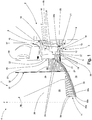
- Fig. 1 shows a perspective view of an adapter connector 3, connecting a fluidization apparatus 1 and a granulator 2, of a first exemplary embodiment of a device 4 according to the invention, in partial section.
- the granulator 2 producing the granules is designed as a twin-screw extruder.
- the granulator 2 comprises an outlet 5.
- the outlet 5 is designed in the form of two ends 6 of the extruder screws.
- the granulator 2 has a flange 7 for producing a connection 8 with a flange 10 of the adapter connector 3 arranged at the inlet 9 of the adapter connector 3.
- the adapter stub 3 of the device 4 is between the one first inflow base 11 arranged having fluidization apparatus 1 and the granulator 2 and connects them to one another.
- the adapter socket 3 comprises an adapter socket housing 13 formed from a pipe section 12 and a flange 10 adjoining it.
- the adapter socket housing 13 has an inner wall 15 having an inner surface 14.
- a second inflow base 16 is arranged on the inner surface 14 of the inner wall 15 of the adapter stub 3.
- the second inflow base 16 is arranged at least partially on the inner wall 15 of the adapter stub 3, that is to say firmly connected to the inner wall 15 of the adapter stub 3.
- the second inflow base 16 divides the adapter stub 3 at least partially into a lower first chamber 17 and an upper second chamber 18 Like. Have.
- the end wall 20a adjoining the granulator 2 and the side walls 19 of the second inflow base 16 arranged in the adapter nozzle 3 in the area of an inner wall 22 of an inlet 23 of the fluidization apparatus 1 are provided with a sealing element 21.
- the adapter stub 3 is sealed in a state connected to the fluidization apparatus 1 and the granulator 2 in such a way that a gaseous medium - also referred to as process air - exclusively through the openings 24 of the second inflow base 16 in the adapter stub 3 flows from the lower first chamber 17 into an upper second chamber 18.
- the second inflow base 16 of the adapter stub 3 can be a multi-part inflow base 16, in particular with multiple layers arranged inflow base plates, be formed.
- the second inflow base 16 of the adapter stub 3 is designed as a single-layer, second inflow base 16.
- the second inflow base 16 is preferably, as shown in the exemplary embodiment, arranged at an angle ⁇ to the longitudinal axis A-A of the adapter connector 3.
- the angle ⁇ is formed in such a way that a gradient is created from the granulator 2 towards the inlet 23 of the fluidization apparatus 1.
- the granules fluidized through the second inflow base 16 in the adapter stub 3 according to the invention which in the fluidized state behave like a liquid, “flow” from the granulator 2 into the fluidization apparatus 1.
- the fluidization apparatus 1 has a distribution chamber 25 and a swirl chamber 26, the distribution chamber 25 and the swirl chamber 26 being separated from one another by a first inflow base 11.
- a process air entering the distribution chamber 25 via an inlet opening (not shown) for the process air is distributed over the first inflow tray 11, in particular evenly, to the swirl chamber 26 and flows through both the first inflow tray 11 and the second inflow tray 16 arranged in the adapter connector 3 in the direction of the Vortex chamber 26.
- the process air is discharged from the fluidization apparatus 1 in an upper section (not shown here) and is preferably cleaned beforehand via a filter (not shown).
- the vortex chamber 26 comprises a displacement body 28 having partition walls 27.
- the vortex chamber 26 is divided into process chambers 29 by the partition walls 27.
- the partition walls 27 extend from the displacement body 28 to one Side wall 30 of the vortex chamber 26.
- the partition walls 27 comprise a sealing element 32 arranged at their outer end 31, in particular in the form of a sealing lip.
- the partition walls 27 also extend from the inflow base 26 at any desired height in the direction of a vertical central axis Z of the fluidization apparatus 1.
- the height of the partition walls 27 is changeable or adaptable and in particular depends on the granulate to be treated.
- the first inflow base 11 of the fluidization apparatus 1 has an upper inflow base plate 33a, a middle inflow base plate 33b and a lower inflow base plate 33c.
- the middle inflow base plate 33b preferably has a sealing element 34, in particular a sealing lip or the like, running around the first inflow base, or forms such a sealing element 34 itself.
- the middle inflow base plate 33b is preferably made of polytetrafluoroethylene (PTFE).
- PTFE polytetrafluoroethylene
- the sealing element 34 of the first inflow base 11 of the fluidization apparatus 1, in particular one of the inflow base plates 33a to 33c seals against the side wall 35 of the distributor chamber 25.
- the sealing element 34 of the first inflow base 11 seals against the second inflow base 16 of the adapter connector 3.
- the individual inflow base plates 33a, 33b and 33c have openings 36a, 36b and 36c.
- the openings 36a to 36c are designed in such a way that they generate a pressure loss for the process air across the two inflow bases 11, 16, this pressure loss being adjustable and set so that granules located in a process chamber 29 are always, that is, fluidization in each process chamber 29 takes place, are fluidized.
- the adapter stub 3 is arranged at the inlet 23 of the fluidization apparatus 1.
- the inlet 23 for the granulate to be treated is arranged in a side wall 35 of the distribution chamber 24.
- the inlet 23 of the fluidization apparatus 1 is arranged in a side wall 35 of the fluidization apparatus 1 in such a way that the inlet 23 has a connection to the distribution chamber 25 and to the swirl chamber 26.
- the side wall 35 of the distribution chamber 25 is connected to the side wall 30 of the vortex chamber 26 via a connection 37, in particular a flange connection.
- the granulate is produced in the granulator 2 by spraying or otherwise adding in particular binder liquid with powdery material, in particular particles, and simultaneous mixing.
- the granules produced in the granulator 2 then enter the upper, second chamber 18 of the adapter connector 3 via the two ends 6 of the granulator 2 in the form of a twin-screw extruder. There the generated, moist granulate is fluidized as it enters the upper, second chamber 18 of the adapter connector 3 by the process air flowing through the second inflow base 16 arranged in the adapter connector 3.
- the granules behave like a liquid and "flow" at an angle ⁇ to the longitudinal axis AA with a gradient from the granulator 2 to the inlet 23 of the fluidization apparatus 1 and the first inflow base 11 arranged in the fluidization apparatus 1 the granules at the outlet 5 of the granulator 2, in the adapter stub 3 and at the inlet 23 of the fluidization apparatus 1 is prevented or significantly reduced.
- the first inflow base 11 arranged on the displacement body 28 and its partition walls 27 rotates around a central axis Z of the fluidization apparatus 1 in the direction of rotation 38 fluidized state treated.
- the granules can, for example, be sprayed with a wide variety of liquids, emulsions, suspensions or the like by means of nozzles (not shown here) arranged in the fluidization apparatus 1 and treated in this way. Due to the constant speed of rotation of the process chambers 29 of the fluidization apparatus 1, the granules are always treated equally and optimally with a constant residence time and then discharged from the fluidization apparatus 1 via an outlet (not shown) of the fluidization apparatus 1.
- the first and the second inflow base 11, 16 can also be designed as a first part 11 of an inflow base and a second part 16 of an inflow base.
- both parts 11, 16 of the inflow base are preferably identical, ie, for example, made of the same material, with the same number of inflow base plates 33 and the same cross section of the openings 24, 36.
- the first and second inflow bases 11, 16 can also be designed identically.
- Fig. 2 shows a perspective illustration of a first exemplary embodiment of the adapter connector 3 according to the invention, which is arranged on the fluidization apparatus 1 and has a longitudinal axis AA, in full section. The section was made along a vertical plane through the longitudinal axis AA of the adapter connector 3.
- the adapter connector 3 is arranged at the inlet 23 of the fluidization apparatus 1 in the side wall 35 of the distribution chamber 25.
- the side wall 35 of the distribution chamber 25 is connected to the side wall 30 of the swirl chamber 26 by means of a connection 37, in particular a flange connection, a sealing element 39 being arranged between the two side walls 30, 35.
- the first inflow base 11, which separates the distribution chamber 25 and the swirl chamber 26 from one another and is arranged in the fluidization apparatus 1, is shown in FIG Fig. 2 not shown.
- the adapter socket 3 has an adapter socket housing 13 with a pipe section 12 and a flange 10 of the adapter socket 3 arranged on the pipe section 12.
- the flange 10 By means of the flange 10 at the inlet 9 of the adapter stub 3, the latter can be connected to a flange 7, not shown here, on the granulator 2.
- a sealing element (not shown), in particular an annular seal or a flat seal or the like, is arranged in the groove 40 of the flange 10.
- the second inflow base 16 which has openings 24 and is configured in a single layer, is partially arranged in the adapter stub 3.
- the side walls 19 of the second inflow base 16 are at least partially firmly connected to the inner surface 14 of the inner wall 15 of the adapter socket housing 13. These Connection is made using the in Fig. 2 dashed line shown there.
- the section 41 of the side wall 19 of the second inflow base 16 arranged in the area of the inner wall 22 of the inlet 23 is sealed off from the inner wall 22 of the inlet 23 of the fluidization apparatus 1 with a sealing element 21 (not shown).
- the seal 21 is arranged on the end wall 20a.
- the adapter stub 3 is arranged at the inlet 23 of the fluidization apparatus 1 in the side wall 35 of the distribution chamber 25.
- the side wall 35 of the distribution chamber 25 is connected to the side wall 30 of the swirl chamber 26 via the connection 37 having a sealing element 39.
- Fig. 3 shown that the single-layer or single-layered, openings 24 having second inflow base 16 of the adapter connector 3 is arranged along the longitudinal axis AA of the adapter connector 3 at an angle ⁇ to this.
- the inflow base 3 protrudes from the adapter socket 3 on the side of the fluidization apparatus 1 and, in the exemplary embodiment, protrudes slightly into the fluidization apparatus 1.
- Due to the angle ⁇ with respect to the longitudinal axis AA of the adapter connector 3, the second inflow base 16 has a gradient from the inlet 9 of the adapter connector 3 in the direction of the inlet 23 of the fluidization apparatus 1.
- the second inflow base 16 does not extend through the entire Adapter stub 3, but ends after about 3/4 of the length of the adapter stub 3 in this.
- a sealing element 42 preferably an annular seal, for example an O-ring, is arranged in the groove 40 of the pipe section 12 of the flange 10 of the adapter socket housing 13.
- the two Figs. 4 and 5 show a side view of a second or third exemplary embodiment of the adapter connector 3 according to FIG Fig. 2 in full cut.
- the second and third exemplary embodiments have a modified, optimized inlet section area 43 for process air flowing from the distributor chamber 25 of the fluidization apparatus 1 into the lower first chamber 17.
- the optimized inlet section area 43 leads to an improved fluidization of the granules entering the upper second chamber 18 from the outlet 5 of the granulator 2 (not shown).
- FIG. 6 a perspective illustration of a first inflow base 11 of the fluidization apparatus 1 having three inflow base plates 33a to 33c is shown in partial section.
- the vortex chamber 26 of the fluidization apparatus 1 is divided into process chambers 29 by the partition walls 27.
- the lower inflow base plate 33c has openings 36c which correspond to the openings 36b of the middle inflow base plate 33b.
- the lower inflow base plate 33c has the function of holding and stabilizing the central inflow base plate 33b designed as a sealing base.
- the lower inflow base plate 33c like the upper inflow base plate 33a, is preferably made of steel, in particular stainless steel.
- the inflow base plate 33b designed as a sealing base is preferably made from polytetrafluoroethylene (PTFE).
- the middle inflow base plate 33b can be used as a sealing base, it must either have a larger diameter compared to the lower and upper inflow base plates 33a or 33b or comprise a sealing element 34 (not shown) at its outer end 43.
- the middle inflow base plate 33b forms the sealing element 34 itself at its outer end 43 due to its larger diameter compared to the inflow base plates 33a and 33c.
- the upper inflow base plate 33a of the first inflow base 11 arranged in the fluidization apparatus 1 has, in the preferred embodiment shown in the exemplary embodiment, smaller openings 36a, in particular in the form of a slot with a width of 0.2 mm.
- the pressure loss generated above the first inflow base 11 is set through the openings 36a to 36c of the inflow base plates 33a to 33c, in particular through the upper inflow base plate 36a.
- the granulate to be treated is optimally fluidized, ie the process air also fluidizes the generated, moist granulate entering the process chamber 29.
- Such a configuration of the first inflow base 11 arranged in the fluidization apparatus, in particular with the middle inflow base plate 33b designed as a sealing base, allows it to be rotated in the fluidization apparatus 1 about a central axis Z and at the same time without showing any signs of wear the distribution chamber 25 of the vortex chamber 26 and that in the adapter nozzle 3, the second inflow base 16 arranged to be sealed off from the first inflow base 11.
- Fig. 7 shows a side view of a full section through a first inflow base 11 having three inflow base plates 33a to 33c and arranged in the fluidization apparatus 1.
- the middle inflow base plate 33b has a larger diameter compared to the upper and lower inflow base plates 33a and 33c. In the illustrated embodiment, the middle inflow base plate 33b thereby forms a sealing element 34 at its outer end 43.
- the openings 36a to 36c of the inflow base plates 33a to 33c are arranged one above the other in the exemplary embodiment, with FIG Fig. 6 the openings 36a of the inflow base plate 33a have a smaller width, not shown here, compared to the openings 36b and 36c.
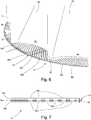
- FIG Fig. 8 A perspective illustration of the device 4 according to the invention, the fluidization apparatus 1 having the adapter nozzle 3 and the granulator 2 producing the granules being separated from one another in FIG Fig. 8 shown.
- Fig. 9 is a perspective view of the device 4 according to the invention, the fluidization apparatus 1 and the granulator 2 producing the granules being connected to one another by means of the adapter connector 3.
- the particulate material entering the granulator 2 via feed lines 47 is mixed with binder liquid in the granulator and the granulate is formed.
- the granulate emerging from the granulator 2 is fluidized in the adapter nozzle 3 and thereby conveyed into the fluidization apparatus 1.
- There the granulate is treated in the process chamber 29 (not shown).
- the process chambers 29 rotate about the central axis Z in the direction of rotation 38 having displacement body 28 together with the first inflow plate 11 is driven by a motor 48 having a gear, preferably an electric, servo or torque motor.
- the motor 48 preferably has a constant torque over its entire speed range. This sets a defined dwell time of the granules in the fluidization apparatus until the treated granules are discharged from the device 4 at the outlet 49 of the fluidization apparatus 1.
- Fig. 10 shows a perspective illustration of a second exemplary embodiment, not according to the invention, of a device 4 having a fluidization apparatus 1 and a granulator 2, in partial section.
- the second exemplary embodiment of the device 4 does not have an adapter connector 3.
- the granulator 2 is arranged directly on the fluidization apparatus 1, that is to say without a connecting part such as an adapter stub 3.
- the fluidization apparatus 1 comprises a swirl chamber 26 which is separated from a distributor chamber 25 by an inflow base 11.
- the inflow base 11 has three layers and has inflow base plates 33a to 33c.
- the inflow base plate 33b which has a larger diameter compared to the inflow base plates 33a and 33c, seals between the distributor chamber 25 and the vortex chamber 26 against a side wall 35 of the distributor chamber 26 and against the outlet 5 of the granulator 2 by means of the sealing element 34 formed by the inflow base plate 33b itself .
- the in the fluidization apparatus 1 on the displacement body 28 and the Inflow base 11 arranged on partition walls 27 rotates about central axis Z in direction of rotation 38.
- the granulator 2 is designed as a twin-screw extruder and has an outlet 5 for the moist granulate produced in the form of two ends 6 of the extruder screws.
- the granulator 2 is connected to the fluidization apparatus 1 in such a way that the outlet 5 of the granulator 2 directly adjoins the inflow base 11 arranged in the fluidization apparatus 1.
- An end wall 50 of the outlet 5 of the granulator 2 advantageously corresponds in its design, e.g. radius and curvature, to an inner wall 51 of the fluidization apparatus 1. This ensures continuous operation, since the partition walls 27 can rotate past the outlet 5 of the granulator 2.
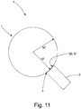
- Fig. 11 a schematic representation of the in Fig. 10 shown second embodiment of a device 4 is shown.
- Fig. 11 In their training (in Fig. 11 shown as a bold line) of the end wall 50 of the outlet 5 of the granulator 2 corresponding inner wall 51 of the fluidization apparatus 1 of the device 4 is identical in its radius 53 to the curvature of the end wall 50 with the radius 52, so that the outlet 5 forming The ends 6 of the extruder screws do not protrude into the swirl chamber 26.
Landscapes
- Chemical & Material Sciences (AREA)
- Organic Chemistry (AREA)
- Chemical Kinetics & Catalysis (AREA)
- Glanulating (AREA)
- Devices And Processes Conducted In The Presence Of Fluids And Solid Particles (AREA)
- Processing And Handling Of Plastics And Other Materials For Molding In General (AREA)
Applications Claiming Priority (2)
| Application Number | Priority Date | Filing Date | Title |
|---|---|---|---|
| DE102018208930.2A DE102018208930A1 (de) | 2018-06-06 | 2018-06-06 | Vorrichtung und Verfahren zur Herstellung und Behandlung von Granulat sowie Adapterstutzen zur Verbindung eines ein Granulat erzeugenden Granulators und eines Fluidisierungsapparates |
| PCT/EP2019/062946 WO2019233746A1 (de) | 2018-06-06 | 2019-05-20 | Vorrichtung und verfahren zur herstellung und behandlung von granulat sowie adapterstutzen zur verbindung eines ein granulat erzeugenden granulators und eines fluidisierungsapparates |
Publications (2)
| Publication Number | Publication Date |
|---|---|
| EP3801862A1 EP3801862A1 (de) | 2021-04-14 |
| EP3801862B1 true EP3801862B1 (de) | 2021-12-01 |
Family
ID=66625975
Family Applications (1)
| Application Number | Title | Priority Date | Filing Date |
|---|---|---|---|
| EP19725709.0A Active EP3801862B1 (de) | 2018-06-06 | 2019-05-20 | Vorrichtung und verfahren zur herstellung und behandlung von granulat mit einem adapterstutzen zur verbindung eines ein granulat erzeugenden granulators und eines fluidisierungsapparates |
Country Status (7)
| Country | Link |
|---|---|
| US (1) | US12145126B2 (https=) |
| EP (1) | EP3801862B1 (https=) |
| JP (1) | JP7377219B2 (https=) |
| CN (1) | CN112689534B (https=) |
| DE (1) | DE102018208930A1 (https=) |
| ES (1) | ES2906625T3 (https=) |
| WO (1) | WO2019233746A1 (https=) |
Families Citing this family (2)
| Publication number | Priority date | Publication date | Assignee | Title |
|---|---|---|---|---|
| DE102021200162A1 (de) * | 2021-01-11 | 2022-07-14 | Glatt Gesellschaft Mit Beschränkter Haftung | Fluidisierungsapparat zur Behandlung von partikelförmigem Material |
| EP4338829A1 (en) | 2022-09-14 | 2024-03-20 | SaltX Technology AB | A fluidization pad, and a fluidized bed apparatus comprising a fluidization pad |
Family Cites Families (26)
| Publication number | Priority date | Publication date | Assignee | Title |
|---|---|---|---|---|
| DE1556091A1 (de) * | 1967-09-21 | 1970-01-15 | Schloz Motor Condensator | Foerderrinne zum Foerdern von feinkoernigem und pulverfoermigem Gut mittels eines durch eine durchlaessige Platte eingefuehrten gasfoermigen Mediums |
| CH503641A (fr) * | 1969-05-14 | 1971-02-28 | Aerocoat Sa | Procédé de fluidisation et dispositif pour la mise en oeuvre de ce procédé |
| IT1016057B (it) | 1974-06-17 | 1977-05-30 | Centro Speriment Metallurg | Piastra di reattori a letto fluido |
| JPS53154587U (https=) * | 1977-05-11 | 1978-12-05 | ||
| JPS61110083U (https=) | 1984-12-20 | 1986-07-12 | ||
| DE4000572C1 (https=) * | 1990-01-10 | 1991-02-21 | Herbert 7853 Steinen De Huettlin | |
| DE4000571C1 (https=) * | 1990-01-10 | 1991-06-06 | Herbert 7853 Steinen De Huettlin | |
| JPH053891U (ja) | 1991-07-03 | 1993-01-22 | パウテツク株式会社 | 粉粒体の連続流動乾燥装置 |
| JP3417669B2 (ja) | 1994-07-14 | 2003-06-16 | 塩野義製薬株式会社 | 槽移動式流動乾燥装置 |
| DE10144747A1 (de) | 2001-09-11 | 2003-03-27 | Buehler Ag | Kontinuierliche thermische Behandlung von Schüttgütern |
| DE102004038003A1 (de) * | 2004-08-04 | 2006-03-16 | Spörl KG | Vorrichtung zur pneumatischen Förderung von Schüttgut |
| TWI440658B (zh) | 2005-08-31 | 2014-06-11 | Gala Inc | 用於水中粒化具減低含水量的聚合體生物材料複合物之方法及裝置 |
| EP1764320A1 (de) * | 2005-09-15 | 2007-03-21 | Claudius Peters Technologies GmbH | Förderrohr zur vereinfachten pneumatischen Förderung |
| ES2294741T3 (es) * | 2006-02-07 | 2008-04-01 | Ibau Hamburg Ingenieurgesellschaft | Dispositivo de transporte neumatico de material pulverulento. |
| ATE481164T1 (de) | 2007-02-27 | 2010-10-15 | Gea Pharma Systems Nv | Kontinuierlich arbeitende granulations- und trocknungsvorrichtung mit messeinheiten und verfahren zur kontinuierlichen granulation und trocknung |
| US7883039B2 (en) * | 2007-02-27 | 2011-02-08 | Collette Nv | Continuous granulating and drying apparatus including measurement units |
| WO2010016342A1 (ja) * | 2008-08-05 | 2010-02-11 | フロイント産業株式会社 | 流動層装置 |
| DE202010005876U1 (de) * | 2010-04-20 | 2011-08-10 | Hermann J. Linder | Vorrichtung zum Einspeisen oder Anlegen eines Druckmediums in eine Feststoffe fördernde Rohrleitung |
| CN203061148U (zh) * | 2013-01-10 | 2013-07-17 | 南京高正农用化工有限公司 | 一种可连续化自动生产的粉体挤压造粒系统 |
| DE102013102133B4 (de) | 2013-03-05 | 2014-10-09 | L.B. Bohle Maschinen + Verfahren Gmbh | Wirbelschicht-Trockner mit mehreren Kammern |
| DE102013005921A1 (de) * | 2013-04-03 | 2014-10-09 | Glatt Ingenieurtechnik Gmbh | Fluidisierungsapparat |
| DE102013015190A1 (de) | 2013-09-11 | 2015-03-12 | Automatik Plastics Machinery Gmbh | Verfahren zur Herstellung von oberflächig kristallinen sphärischen Granulaten mittelsTrockenheißabschlag und Vorrichtung zur Durchführung des Verfahrens |
| JP6234166B2 (ja) | 2013-10-29 | 2017-11-22 | フロイント産業株式会社 | 連続造粒装置 |
| DE102014202236A1 (de) * | 2014-02-07 | 2015-08-13 | Siemens Aktiengesellschaft | Hilfsgaselement zum Befördern von Staubströmen |
| JP6746685B2 (ja) | 2016-03-22 | 2020-08-26 | 株式会社日清製粉グループ本社 | 小麦粉組成物の製造方法 |
| CN206746480U (zh) | 2017-03-14 | 2017-12-15 | 广东和平君乐药业有限公司 | 一种沸腾干燥制粒机 |
-
2018
- 2018-06-06 DE DE102018208930.2A patent/DE102018208930A1/de not_active Withdrawn
-
2019
- 2019-05-20 JP JP2020567748A patent/JP7377219B2/ja active Active
- 2019-05-20 US US16/972,098 patent/US12145126B2/en active Active
- 2019-05-20 WO PCT/EP2019/062946 patent/WO2019233746A1/de not_active Ceased
- 2019-05-20 CN CN201980052208.9A patent/CN112689534B/zh active Active
- 2019-05-20 ES ES19725709T patent/ES2906625T3/es active Active
- 2019-05-20 EP EP19725709.0A patent/EP3801862B1/de active Active
Also Published As
| Publication number | Publication date |
|---|---|
| DE102018208930A1 (de) | 2019-12-12 |
| EP3801862A1 (de) | 2021-04-14 |
| JP7377219B2 (ja) | 2023-11-09 |
| US12145126B2 (en) | 2024-11-19 |
| WO2019233746A1 (de) | 2019-12-12 |
| CN112689534B (zh) | 2023-10-27 |
| JP2021525647A (ja) | 2021-09-27 |
| ES2906625T3 (es) | 2022-04-19 |
| US20210220786A1 (en) | 2021-07-22 |
| CN112689534A (zh) | 2021-04-20 |
Similar Documents
| Publication | Publication Date | Title |
|---|---|---|
| DE69427350T2 (de) | Extrusionsmatrize | |
| EP0436787B1 (de) | Fliessbettapparatur zum Herstellen und/oder Weiterbehandeln schüttfähigen Gutes | |
| EP2981352B1 (de) | Rotationstrocknerstern zur behandlung von feststoffpartikeln | |
| EP1622711B1 (de) | Verfahren und vorrichtung zum aufbringen von flüssigkeiten in eine feststoffströmung eines strahlschichtapparates | |
| DE4118433C2 (de) | Fließbettapparatur zum Behandeln partikelförmigen Gutes | |
| DE19507281A1 (de) | Trogüberzugsvorrichtung | |
| EP3801862B1 (de) | Vorrichtung und verfahren zur herstellung und behandlung von granulat mit einem adapterstutzen zur verbindung eines ein granulat erzeugenden granulators und eines fluidisierungsapparates | |
| DE10122675B4 (de) | Strangpressvorrichtung für Keramikformprodukte | |
| EP0545044A2 (de) | Vorrichtung zum Dragieren von stückigen Produkten, insbesondere Pillen und Tabletten | |
| EP3120092A1 (de) | Trocknungsanlage mit mehreren ortsfesten kammern | |
| DE10232863A1 (de) | Zerstäubungsdüse mit rotativem Ringspalt | |
| DE10125732B4 (de) | Filter zum Entstauben von ein partikelförmiges Gut enthaltende Prozeßluft in einer Prozeßapparatur sowie derartige Prozeßapparatur | |
| DE10138333C2 (de) | Vorrichtung zum Auspressen fließfähiger Substanzen | |
| EP0744212B1 (de) | Trommelcoater | |
| DE10104047B4 (de) | Vorrichtung zur Trockenbeleimung von Teilchen in Form von Fasern und Spänen | |
| EP1893327A1 (de) | Einrichtung zur führung eines gases für vorrichtungen zum behandeln körnigen gutes durch trocknen, filmcoaten oder beschichten, insbesondere zulufteinheit und vorrichtung mit einer derartigen einrichtung | |
| EP3051241B1 (de) | Aufgabevorrichtung für pastöse produkte auf ein band | |
| DE4237419C2 (de) | Rohrweiche für pneumatisch zu fördernde Schüttgüter | |
| EP4274675B1 (de) | Verfahren zur behandlung von partikelförmigem material in einem fluidisierungsapparat | |
| WO1998040294A1 (de) | Vorrichtung zum fluidisieren und transportieren von feinkörnigen, pulverförmigen oder kurzfaserigen materialien innerhalb eines schlauches, rohres oder behälters | |
| DE4343289A1 (de) | Extruder | |
| DE102004046248B4 (de) | Vorrichtung zur variablen Gaszufuhr für Strahlschichtapparaturen | |
| EP4041515A1 (de) | Anordnung zum granulieren von extrudiertem material | |
| DE20307558U1 (de) | Wirbelschichtapparat |
Legal Events
| Date | Code | Title | Description |
|---|---|---|---|
| STAA | Information on the status of an ep patent application or granted ep patent |
Free format text: STATUS: UNKNOWN |
|
| STAA | Information on the status of an ep patent application or granted ep patent |
Free format text: STATUS: THE INTERNATIONAL PUBLICATION HAS BEEN MADE |
|
| PUAI | Public reference made under article 153(3) epc to a published international application that has entered the european phase |
Free format text: ORIGINAL CODE: 0009012 |
|
| STAA | Information on the status of an ep patent application or granted ep patent |
Free format text: STATUS: REQUEST FOR EXAMINATION WAS MADE |
|
| 17P | Request for examination filed |
Effective date: 20201120 |
|
| AK | Designated contracting states |
Kind code of ref document: A1 Designated state(s): AL AT BE BG CH CY CZ DE DK EE ES FI FR GB GR HR HU IE IS IT LI LT LU LV MC MK MT NL NO PL PT RO RS SE SI SK SM TR |
|
| AX | Request for extension of the european patent |
Extension state: BA ME |
|
| GRAP | Despatch of communication of intention to grant a patent |
Free format text: ORIGINAL CODE: EPIDOSNIGR1 |
|
| STAA | Information on the status of an ep patent application or granted ep patent |
Free format text: STATUS: GRANT OF PATENT IS INTENDED |
|
| INTG | Intention to grant announced |
Effective date: 20210629 |
|
| DAV | Request for validation of the european patent (deleted) | ||
| DAX | Request for extension of the european patent (deleted) | ||
| GRAS | Grant fee paid |
Free format text: ORIGINAL CODE: EPIDOSNIGR3 |
|
| GRAA | (expected) grant |
Free format text: ORIGINAL CODE: 0009210 |
|
| STAA | Information on the status of an ep patent application or granted ep patent |
Free format text: STATUS: THE PATENT HAS BEEN GRANTED |
|
| AK | Designated contracting states |
Kind code of ref document: B1 Designated state(s): AL AT BE BG CH CY CZ DE DK EE ES FI FR GB GR HR HU IE IS IT LI LT LU LV MC MK MT NL NO PL PT RO RS SE SI SK SM TR |
|
| REG | Reference to a national code |
Ref country code: GB Ref legal event code: FG4D Free format text: NOT ENGLISH |
|
| REG | Reference to a national code |
Ref country code: AT Ref legal event code: REF Ref document number: 1451235 Country of ref document: AT Kind code of ref document: T Effective date: 20211215 Ref country code: CH Ref legal event code: EP |
|
| REG | Reference to a national code |
Ref country code: IE Ref legal event code: FG4D Free format text: LANGUAGE OF EP DOCUMENT: GERMAN |
|
| REG | Reference to a national code |
Ref country code: DE Ref legal event code: R096 Ref document number: 502019002927 Country of ref document: DE |
|
| REG | Reference to a national code |
Ref country code: SE Ref legal event code: TRGR |
|
| REG | Reference to a national code |
Ref country code: LT Ref legal event code: MG9D |
|
| REG | Reference to a national code |
Ref country code: NL Ref legal event code: MP Effective date: 20211201 |
|
| REG | Reference to a national code |
Ref country code: ES Ref legal event code: FG2A Ref document number: 2906625 Country of ref document: ES Kind code of ref document: T3 Effective date: 20220419 |
|
| PG25 | Lapsed in a contracting state [announced via postgrant information from national office to epo] |
Ref country code: RS Free format text: LAPSE BECAUSE OF FAILURE TO SUBMIT A TRANSLATION OF THE DESCRIPTION OR TO PAY THE FEE WITHIN THE PRESCRIBED TIME-LIMIT Effective date: 20211201 Ref country code: LT Free format text: LAPSE BECAUSE OF FAILURE TO SUBMIT A TRANSLATION OF THE DESCRIPTION OR TO PAY THE FEE WITHIN THE PRESCRIBED TIME-LIMIT Effective date: 20211201 Ref country code: FI Free format text: LAPSE BECAUSE OF FAILURE TO SUBMIT A TRANSLATION OF THE DESCRIPTION OR TO PAY THE FEE WITHIN THE PRESCRIBED TIME-LIMIT Effective date: 20211201 Ref country code: BG Free format text: LAPSE BECAUSE OF FAILURE TO SUBMIT A TRANSLATION OF THE DESCRIPTION OR TO PAY THE FEE WITHIN THE PRESCRIBED TIME-LIMIT Effective date: 20220301 |
|
| PG25 | Lapsed in a contracting state [announced via postgrant information from national office to epo] |
Ref country code: PL Free format text: LAPSE BECAUSE OF FAILURE TO SUBMIT A TRANSLATION OF THE DESCRIPTION OR TO PAY THE FEE WITHIN THE PRESCRIBED TIME-LIMIT Effective date: 20211201 Ref country code: NO Free format text: LAPSE BECAUSE OF FAILURE TO SUBMIT A TRANSLATION OF THE DESCRIPTION OR TO PAY THE FEE WITHIN THE PRESCRIBED TIME-LIMIT Effective date: 20220301 Ref country code: LV Free format text: LAPSE BECAUSE OF FAILURE TO SUBMIT A TRANSLATION OF THE DESCRIPTION OR TO PAY THE FEE WITHIN THE PRESCRIBED TIME-LIMIT Effective date: 20211201 Ref country code: HR Free format text: LAPSE BECAUSE OF FAILURE TO SUBMIT A TRANSLATION OF THE DESCRIPTION OR TO PAY THE FEE WITHIN THE PRESCRIBED TIME-LIMIT Effective date: 20211201 Ref country code: GR Free format text: LAPSE BECAUSE OF FAILURE TO SUBMIT A TRANSLATION OF THE DESCRIPTION OR TO PAY THE FEE WITHIN THE PRESCRIBED TIME-LIMIT Effective date: 20220302 |
|
| PG25 | Lapsed in a contracting state [announced via postgrant information from national office to epo] |
Ref country code: NL Free format text: LAPSE BECAUSE OF FAILURE TO SUBMIT A TRANSLATION OF THE DESCRIPTION OR TO PAY THE FEE WITHIN THE PRESCRIBED TIME-LIMIT Effective date: 20211201 |
|
| PG25 | Lapsed in a contracting state [announced via postgrant information from national office to epo] |
Ref country code: SM Free format text: LAPSE BECAUSE OF FAILURE TO SUBMIT A TRANSLATION OF THE DESCRIPTION OR TO PAY THE FEE WITHIN THE PRESCRIBED TIME-LIMIT Effective date: 20211201 Ref country code: SK Free format text: LAPSE BECAUSE OF FAILURE TO SUBMIT A TRANSLATION OF THE DESCRIPTION OR TO PAY THE FEE WITHIN THE PRESCRIBED TIME-LIMIT Effective date: 20211201 Ref country code: RO Free format text: LAPSE BECAUSE OF FAILURE TO SUBMIT A TRANSLATION OF THE DESCRIPTION OR TO PAY THE FEE WITHIN THE PRESCRIBED TIME-LIMIT Effective date: 20211201 Ref country code: PT Free format text: LAPSE BECAUSE OF FAILURE TO SUBMIT A TRANSLATION OF THE DESCRIPTION OR TO PAY THE FEE WITHIN THE PRESCRIBED TIME-LIMIT Effective date: 20220401 Ref country code: EE Free format text: LAPSE BECAUSE OF FAILURE TO SUBMIT A TRANSLATION OF THE DESCRIPTION OR TO PAY THE FEE WITHIN THE PRESCRIBED TIME-LIMIT Effective date: 20211201 |
|
| REG | Reference to a national code |
Ref country code: DE Ref legal event code: R097 Ref document number: 502019002927 Country of ref document: DE |
|
| PG25 | Lapsed in a contracting state [announced via postgrant information from national office to epo] |
Ref country code: IS Free format text: LAPSE BECAUSE OF FAILURE TO SUBMIT A TRANSLATION OF THE DESCRIPTION OR TO PAY THE FEE WITHIN THE PRESCRIBED TIME-LIMIT Effective date: 20220401 |
|
| PLBE | No opposition filed within time limit |
Free format text: ORIGINAL CODE: 0009261 |
|
| STAA | Information on the status of an ep patent application or granted ep patent |
Free format text: STATUS: NO OPPOSITION FILED WITHIN TIME LIMIT |
|
| PG25 | Lapsed in a contracting state [announced via postgrant information from national office to epo] |
Ref country code: DK Free format text: LAPSE BECAUSE OF FAILURE TO SUBMIT A TRANSLATION OF THE DESCRIPTION OR TO PAY THE FEE WITHIN THE PRESCRIBED TIME-LIMIT Effective date: 20211201 Ref country code: AL Free format text: LAPSE BECAUSE OF FAILURE TO SUBMIT A TRANSLATION OF THE DESCRIPTION OR TO PAY THE FEE WITHIN THE PRESCRIBED TIME-LIMIT Effective date: 20211201 |
|
| 26N | No opposition filed |
Effective date: 20220902 |
|
| PG25 | Lapsed in a contracting state [announced via postgrant information from national office to epo] |
Ref country code: MC Free format text: LAPSE BECAUSE OF FAILURE TO SUBMIT A TRANSLATION OF THE DESCRIPTION OR TO PAY THE FEE WITHIN THE PRESCRIBED TIME-LIMIT Effective date: 20211201 Ref country code: LU Free format text: LAPSE BECAUSE OF NON-PAYMENT OF DUE FEES Effective date: 20220520 |
|
| P01 | Opt-out of the competence of the unified patent court (upc) registered |
Effective date: 20230519 |
|
| PG25 | Lapsed in a contracting state [announced via postgrant information from national office to epo] |
Ref country code: MK Free format text: LAPSE BECAUSE OF FAILURE TO SUBMIT A TRANSLATION OF THE DESCRIPTION OR TO PAY THE FEE WITHIN THE PRESCRIBED TIME-LIMIT Effective date: 20211201 Ref country code: CY Free format text: LAPSE BECAUSE OF FAILURE TO SUBMIT A TRANSLATION OF THE DESCRIPTION OR TO PAY THE FEE WITHIN THE PRESCRIBED TIME-LIMIT Effective date: 20211201 |
|
| PG25 | Lapsed in a contracting state [announced via postgrant information from national office to epo] |
Ref country code: HU Free format text: LAPSE BECAUSE OF FAILURE TO SUBMIT A TRANSLATION OF THE DESCRIPTION OR TO PAY THE FEE WITHIN THE PRESCRIBED TIME-LIMIT; INVALID AB INITIO Effective date: 20190520 |
|
| PG25 | Lapsed in a contracting state [announced via postgrant information from national office to epo] |
Ref country code: MT Free format text: LAPSE BECAUSE OF FAILURE TO SUBMIT A TRANSLATION OF THE DESCRIPTION OR TO PAY THE FEE WITHIN THE PRESCRIBED TIME-LIMIT Effective date: 20211201 |
|
| PGFP | Annual fee paid to national office [announced via postgrant information from national office to epo] |
Ref country code: DE Payment date: 20250324 Year of fee payment: 7 |
|
| PGFP | Annual fee paid to national office [announced via postgrant information from national office to epo] |
Ref country code: GB Payment date: 20250522 Year of fee payment: 7 Ref country code: ES Payment date: 20250616 Year of fee payment: 7 |
|
| PGFP | Annual fee paid to national office [announced via postgrant information from national office to epo] |
Ref country code: BE Payment date: 20250520 Year of fee payment: 7 Ref country code: IT Payment date: 20250530 Year of fee payment: 7 |
|
| PGFP | Annual fee paid to national office [announced via postgrant information from national office to epo] |
Ref country code: FR Payment date: 20250526 Year of fee payment: 7 |
|
| PGFP | Annual fee paid to national office [announced via postgrant information from national office to epo] |
Ref country code: CH Payment date: 20250601 Year of fee payment: 7 |
|
| PGFP | Annual fee paid to national office [announced via postgrant information from national office to epo] |
Ref country code: AT Payment date: 20250519 Year of fee payment: 7 |
|
| PGFP | Annual fee paid to national office [announced via postgrant information from national office to epo] |
Ref country code: TR Payment date: 20250514 Year of fee payment: 7 |
|
| PGFP | Annual fee paid to national office [announced via postgrant information from national office to epo] |
Ref country code: CZ Payment date: 20250507 Year of fee payment: 7 |
|
| PGFP | Annual fee paid to national office [announced via postgrant information from national office to epo] |
Ref country code: IE Payment date: 20250522 Year of fee payment: 7 |
|
| PGFP | Annual fee paid to national office [announced via postgrant information from national office to epo] |
Ref country code: SE Payment date: 20250522 Year of fee payment: 7 |
|
| PG25 | Lapsed in a contracting state [announced via postgrant information from national office to epo] |
Ref country code: SI Free format text: LAPSE BECAUSE OF FAILURE TO SUBMIT A TRANSLATION OF THE DESCRIPTION OR TO PAY THE FEE WITHIN THE PRESCRIBED TIME-LIMIT Effective date: 20211201 |