EP3800310A1 - Serrure du véhicule automobile - Google Patents
Serrure du véhicule automobile Download PDFInfo
- Publication number
- EP3800310A1 EP3800310A1 EP20197436.7A EP20197436A EP3800310A1 EP 3800310 A1 EP3800310 A1 EP 3800310A1 EP 20197436 A EP20197436 A EP 20197436A EP 3800310 A1 EP3800310 A1 EP 3800310A1
- Authority
- EP
- European Patent Office
- Prior art keywords
- motor vehicle
- lever
- drive
- vehicle lock
- electric motor
- Prior art date
- Legal status (The legal status is an assumption and is not a legal conclusion. Google has not performed a legal analysis and makes no representation as to the accuracy of the status listed.)
- Granted
Links
- 230000000903 blocking effect Effects 0.000 claims abstract description 41
- 230000007246 mechanism Effects 0.000 claims abstract description 35
- 230000003993 interaction Effects 0.000 description 4
- 238000000034 method Methods 0.000 description 3
- 230000007704 transition Effects 0.000 description 3
- 230000000694 effects Effects 0.000 description 2
- 230000009471 action Effects 0.000 description 1
- 230000008569 process Effects 0.000 description 1
Images


Classifications
-
- E—FIXED CONSTRUCTIONS
- E05—LOCKS; KEYS; WINDOW OR DOOR FITTINGS; SAFES
- E05B—LOCKS; ACCESSORIES THEREFOR; HANDCUFFS
- E05B77/00—Vehicle locks characterised by special functions or purposes
- E05B77/02—Vehicle locks characterised by special functions or purposes for accident situations
-
- E—FIXED CONSTRUCTIONS
- E05—LOCKS; KEYS; WINDOW OR DOOR FITTINGS; SAFES
- E05B—LOCKS; ACCESSORIES THEREFOR; HANDCUFFS
- E05B81/00—Power-actuated vehicle locks
- E05B81/12—Power-actuated vehicle locks characterised by the function or purpose of the powered actuators
- E05B81/14—Power-actuated vehicle locks characterised by the function or purpose of the powered actuators operating on bolt detents, e.g. for unlatching the bolt
-
- E—FIXED CONSTRUCTIONS
- E05—LOCKS; KEYS; WINDOW OR DOOR FITTINGS; SAFES
- E05B—LOCKS; ACCESSORIES THEREFOR; HANDCUFFS
- E05B81/00—Power-actuated vehicle locks
- E05B81/54—Electrical circuits
- E05B81/90—Manual override in case of power failure
-
- E—FIXED CONSTRUCTIONS
- E05—LOCKS; KEYS; WINDOW OR DOOR FITTINGS; SAFES
- E05B—LOCKS; ACCESSORIES THEREFOR; HANDCUFFS
- E05B81/00—Power-actuated vehicle locks
- E05B81/12—Power-actuated vehicle locks characterised by the function or purpose of the powered actuators
- E05B81/16—Power-actuated vehicle locks characterised by the function or purpose of the powered actuators operating on locking elements for locking or unlocking action
Definitions
- the invention relates to a motor vehicle lock, in particular motor vehicle door lock, with a locking mechanism consisting essentially of rotary latch and pawl, and with an electromotive drive for the locking mechanism and a safety lever, the electromotive drive working on the locking mechanism to open in an opening direction and in an unlocking direction deviating therefrom acts on the safety lever to take an unlocked position, and a stop for the electromotive drive is provided, which limits the movement of the drive at least when it is acted upon in the opening direction to cancel the unlocked position and thereby prevents the locking mechanism from opening.
- Motor vehicle locks are used in various forms on and in motor vehicles, for example as motor vehicle door locks in or on a motor vehicle door, tailgate locks, bonnet locks, tank flap locks, but also as locks for a seat lock, a glove box, etc.
- motor vehicle locks are often used these days with electric opening drive, which effect a motorized opening of the locking mechanism consisting essentially of rotary latch and pawl.
- the electromotive drive for the locking mechanism and for opening the locking mechanism is in the prior art according to the DE 10 2012 003 743 A1 also used for other functions.
- the electromotive drive in the above teaching also ensures that mechanical opening of the locking mechanism is guaranteed in emergency operation.
- a locking lever maintains its "locked" position throughout normal operation.
- the well-known electrical resp. electric motor drive equipped with an unlocking lock In this way, the functional reliability is to be increased.
- the stop ensures that the movement of the electromotive drive is limited in the opening direction for releasing the unlocked position.
- the temporary stop ensures that this prevents the locking mechanism from opening electrically.
- the temporarily acting stop is, for example, a pin with a drive, with the aid of which a temporary blockage of an output element is implemented as part of the electromotive drive.
- the said pin interacts with an outer circumference of the output element.
- the well-known motor vehicle door lock has basically proven itself, but still offers room for further improvements. Because the pin for temporarily blocking the output element of the electric motor drive not only has an associated actuator. Instead, the pen is also moved in accordance with signals transmitted to a control unit by at least one sensor. As a result, the design effort is relatively high. The invention aims to provide a remedy here overall.
- the invention is based on the technical problem of adding such a motor vehicle lock and in particular motor vehicle door lock develop that a structurally simple solution is made available.
- a generic motor vehicle lock and in particular motor vehicle door lock is characterized within the scope of the invention in that the stop is arranged on the electric motor drive and interacts with a blocking element.
- the blocking element can in turn be arranged on the safety lever.
- the procedure is usually such that the blocking element is mounted on the same axis as the safety lever.
- the design is usually such that the safety lever is usually designed as a locking lever.
- the safety lever or locking lever is in its "secured” or “locked” position in normal operation.
- An actuating lever mechanism additionally provided in this context consequently goes empty or is blocked so that the locking mechanism cannot be opened. If, on the other hand, the motor vehicle lock and with it the safety lever or locking lever are in their "unlocked” or “unlocked” position, mechanical loading of the actuating lever system usually means that the locking mechanism can be opened mechanically and manually. In this way, the operating lever mechanism can be used redundantly for opening the locking mechanism. An emergency opening or an emergency opening may correspond to this.
- the safety lever which is designed as a locking lever, assumes its “locked” position throughout. Only in the case of special situations, such as in the event of a crash, if the vehicle body is undervoltage or if it fails completely, is the electric motor drive applied in the different unlocking direction to unlock the locking lever. As soon as the safety lever or locking lever has assumed its “unlocked” or “unlocked” position, the motor vehicle lock according to the invention can be opened mechanically redundantly.
- the invention ensures that the motor vehicle lock is still in its initial state and that this initial state has been restored. This is because the stop on the drive, in interaction with the blocking element, prevents the movement of the drive from being limited with the help of the stop in order to cancel the unlocked position. At the same time, this procedure prevents the locking mechanism from opening. Only with a second and renewed application of the electric motor drive following the restoration of the The initial state should then come to the usual electrical opening, which is ensured according to the invention by the interplay between the stop and the blocking element.
- the stop is arranged on an output disk of the drive.
- the drive typically has an electric motor with an output worm on its output shaft.
- the output worm engages on the outside with a toothing of the output disk and ensures that this - and thus the electromotive drive as a whole - can be acted upon both in the opening direction and in the unlocking direction.
- the opening direction corresponds, for example, to a clockwise rotation of the output disk, whereas the unlocking direction is associated with a counterclockwise movement of the output disk.
- the stop generally has a U-shaped receptacle for the blocking element.
- the invention is based on the knowledge that the blocking element, which is typically designed as a blocking lever acted upon by the spring, can interact particularly advantageously with such a U-shaped receptacle. In fact, the end of the blocking lever remote from the axis engages in the receptacle in question to block the drive.
- the blocking lever can be returned to the starting position by its spring-loaded design. In this initial position and to restore the initial state, the safety lever or locking lever again assumes its "secured” or “locked” position.
- the safety lever In order to move the safety lever from its “secured” position to the “unlocked” position, the safety lever generally has an adjusting contour that interacts with a pin on the drive.
- the adjusting contour is usually a U-shaped recess into which the pin in question can move in and out to act on the safety lever.
- the design is also made such that the drive, in addition to the pin and the stop, also has an actuating cam for electrically opening the locking mechanism.
- the stop, the pin and also the actuating cam are generally located on a matching side of the driven pulley as part of the electromotive drive.
- the result is a structurally strikingly simple motor vehicle lock and in particular a motor vehicle door lock which is particularly suitable and set up for realizing the temporary crash redundancy already described in the introduction.
- an emergency opening can still be effected.
- the safety lever is acted upon with the aid of the electric motor drive and opposite to the opening direction, namely in the unlocking direction.
- the safety lever assumes its unlocked position, in which an additional for example provided operating lever mechanism can be acted upon manually and mechanically for emergency opening.
- the drive ensures that when the safety lever is returned to its "secured” position and in the opening direction then completed, a Opening of the locking mechanism is prevented. This ensures the interaction between the stop on the drive and the blocking element.
- a motor vehicle lock is shown, which is a motor vehicle door lock.
- the motor vehicle door lock only has a Figure 1C indicated locking mechanism 1, 2 from rotary latch 1 and pawl 2.
- an indicated release lever 3 is pivoted about its axis in the counterclockwise direction and the pawl 2 in engagement with the rotary latch 1 in the Figure 1C indicated pivoted clockwise.
- the pivoting of the pawl 2 ensures that the rotary latch 1 pivots clockwise about its axis and releases a locking bolt that was previously caught and not shown.
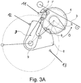
- An electromotive drive 4, 5, 6, 7 provides for the counterclockwise movement of the release lever 3 during the described "electrical opening" of the motor vehicle lock and in particular motor vehicle door lock.
- the electromotive drive 4, 5, 6, 7 does not explicitly have one electric motor shown, which acts on an output pulley 4 shown via a worm on its output shaft.
- the output disk 4 can rotate around its axis both in, for example, in the Figure 1B and 1C as well as 3A and 3B indicated counterclockwise (opening direction ⁇ ) as well as movements in Carry out clockwise as you would in the Figure 2A and 2 B and 4 are shown (direction of development E).
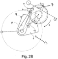
- the electric motor drive 4, 5, 6, 7 also ensures that an additionally provided safety lever 8 is acted upon in the unlocking direction E which deviates from the opening direction ⁇ .
- this unlocking direction E corresponds to the already mentioned movement of the driven pulley 4 in the clockwise direction.
- the safety lever 8 is now acted upon with the help of the electric motor drive 4, 5, 6, 7 to assume an unlocked position, as in the end effect in the functional sequence in the Figure 2A and 2 B is shown.
- the securing lever 8 is a locking lever 8.
- the assumption of the unlocking position as shown in FIG Figure 2B now corresponds to the fact that the safety lever or locking lever 8 is "unlocked” or "unlocked” according to the functional position according to the Figure 2B occupies.
- Such an emergency operation or the emergency opening described can take place, among other things, following a crash or a voltage drop or even the complete failure of a motor vehicle battery, at least when the locking mechanism 1, 2 cannot (no longer) be opened electrically, as shown in FIG the Figures 1A to 1C is shown.
- the motor vehicle door lock can now start from the "unlocked" position of the locking lever 8 in the position according to the Figure 2B be transferred back to its starting position.
- the electromotive drive 4, 5, 6, 7 is acted upon in the opening direction ⁇ in order to transfer the locking lever 8 back into the "locked” position, as it is in the normal state and also for electrical opening in the Figures 1A to 1C occupies.
- a stop 7 is provided according to the invention on the electric motor drive 4, 5, 6, 7, which interacts with a blocking element 9.
- the stop 7 is arranged on the output disk 4 of the electric motor drive 4, 5, 6, 7.
- the output disk 4 also has a pin 6.
- the pin 6, the previously mentioned actuating cam 5 and the stop 7 are all and together on a matching surface, according to the embodiment of the upper side, the output disk 4 and connected to the output disk 4 so that they follow the rotary movements of the output disk 4.
- the safety lever or locking lever 8 is “locked” starting from the position according to FIG Figure 2A in the "unlocked” position after the Figure 2B convicted.
- the securing lever or locking lever 8 has an adjusting contour 10 that interacts with the pin 6.
- the adjusting contour 10 for its part, has a U-shaped recess into which the pin 6 at the transition from the Figure 2A to Figure 2B immersed and thereby moves to the rear edge of the U-shaped recess in the actuation direction or unlocking direction E.
- the locking lever 8 is “locked” starting from its position in the Figure 2A in the "unlocked” position after the Figure 2B convicted.
- the locking lever 8 rotates clockwise about its axis, as indicated by an arrow in FIG Figure 2A is indicated.
- the blocking element or the blocking lever 9 is mounted coaxially to the safety lever or locking lever 8.
- the stop 7 has a U-shaped receptacle 7 'for the blocking element or the blocking lever 9.
- the blocking of the electric motor drive 4, 5, 6, 7 is in accordance with the functional position in the Figure 3B dimensioned in such a way that opening of the locking mechanism 1, 2 is prevented because the actuating cam 5 almost moves against the release lever 3, but does not act upon it in the pawl 2 lifting away from the rotary latch 1.
- Another stop 12 ensures in this context that the locking lever 8 securely in the Figure 2B position shown "unlocked” assumes.
- an additional toggle spring (not shown) ensures that both positions “unlocked” and “locked” of the locking lever 8 are assumed in a bistable manner.
Applications Claiming Priority (1)
| Application Number | Priority Date | Filing Date | Title |
|---|---|---|---|
| DE102019126596.7A DE102019126596A1 (de) | 2019-10-02 | 2019-10-02 | Kraftfahrzeug-Schloss |
Publications (2)
| Publication Number | Publication Date |
|---|---|
| EP3800310A1 true EP3800310A1 (fr) | 2021-04-07 |
| EP3800310B1 EP3800310B1 (fr) | 2022-04-27 |
Family
ID=72615575
Family Applications (1)
| Application Number | Title | Priority Date | Filing Date |
|---|---|---|---|
| EP20197436.7A Active EP3800310B1 (fr) | 2019-10-02 | 2020-09-22 | Serrure du véhicule automobile |
Country Status (2)
| Country | Link |
|---|---|
| EP (1) | EP3800310B1 (fr) |
| DE (1) | DE102019126596A1 (fr) |
Cited By (6)
| Publication number | Priority date | Publication date | Assignee | Title |
|---|---|---|---|---|
| EP3832056A1 (fr) * | 2019-12-03 | 2021-06-09 | Kiekert AG | Fermeture de véhicule automobile, en particulier fermeture de porte de véhicule automobile |
| WO2023232179A1 (fr) | 2022-06-03 | 2023-12-07 | Kiekert Ag | Serrure de véhicule automobile, en particulier serrure de portière de véhicule automobile |
| WO2024012616A1 (fr) * | 2022-07-13 | 2024-01-18 | Kiekert Aktiengesellschaft | Serrure de véhicule à moteur, en particulier serrure de portière de véhicule à moteur |
| WO2024041699A1 (fr) | 2022-08-26 | 2024-02-29 | Kiekert Aktiengesellschaft | Serrure de véhicule automobile |
| DE102022121657A1 (de) | 2022-08-26 | 2024-02-29 | Kiekert Aktiengesellschaft | Kraftfahrzeug-Schloss |
| WO2024041701A1 (fr) | 2022-08-26 | 2024-02-29 | Kiekert Aktiengesellschaft | Serrure de véhicule automobile |
Families Citing this family (3)
| Publication number | Priority date | Publication date | Assignee | Title |
|---|---|---|---|---|
| DE102021126641A1 (de) | 2021-10-14 | 2023-04-20 | Kiekert Aktiengesellschaft | Kraftfahrzeug-Schloss insbesondere Kraftfahrzeug-Türschloss |
| DE102021128448A1 (de) | 2021-11-02 | 2023-05-04 | Kiekert Aktiengesellschaft | Kraftfahrzeug-Schloss insbesondere Kraftfahrzeug-Türschloss |
| DE102021132141A1 (de) | 2021-12-07 | 2023-06-07 | Kiekert Aktiengesellschaft | Kraftfahrzeug-Schloss |
Citations (3)
| Publication number | Priority date | Publication date | Assignee | Title |
|---|---|---|---|---|
| DE102012003743A1 (de) | 2012-02-28 | 2013-08-29 | Kiekert Aktiengesellschaft | Kraftfahrzeugtürverschluss |
| DE102017124520A1 (de) * | 2017-10-20 | 2019-04-25 | Kiekert Ag | Kraftfahrzeugtürschloss |
| DE102017124529A1 (de) | 2017-10-20 | 2019-04-25 | Kiekert Ag | Kraftfahrzeugtürschloss |
-
2019
- 2019-10-02 DE DE102019126596.7A patent/DE102019126596A1/de active Pending
-
2020
- 2020-09-22 EP EP20197436.7A patent/EP3800310B1/fr active Active
Patent Citations (3)
| Publication number | Priority date | Publication date | Assignee | Title |
|---|---|---|---|---|
| DE102012003743A1 (de) | 2012-02-28 | 2013-08-29 | Kiekert Aktiengesellschaft | Kraftfahrzeugtürverschluss |
| DE102017124520A1 (de) * | 2017-10-20 | 2019-04-25 | Kiekert Ag | Kraftfahrzeugtürschloss |
| DE102017124529A1 (de) | 2017-10-20 | 2019-04-25 | Kiekert Ag | Kraftfahrzeugtürschloss |
Cited By (10)
| Publication number | Priority date | Publication date | Assignee | Title |
|---|---|---|---|---|
| EP3832056A1 (fr) * | 2019-12-03 | 2021-06-09 | Kiekert AG | Fermeture de véhicule automobile, en particulier fermeture de porte de véhicule automobile |
| WO2023232179A1 (fr) | 2022-06-03 | 2023-12-07 | Kiekert Ag | Serrure de véhicule automobile, en particulier serrure de portière de véhicule automobile |
| DE102022114103A1 (de) | 2022-06-03 | 2023-12-14 | Kiekert Aktiengesellschaft | Kraftfahrzeug-Schloss insbesondere Kraftfahrzeug-Türschloss |
| WO2024012616A1 (fr) * | 2022-07-13 | 2024-01-18 | Kiekert Aktiengesellschaft | Serrure de véhicule à moteur, en particulier serrure de portière de véhicule à moteur |
| WO2024041699A1 (fr) | 2022-08-26 | 2024-02-29 | Kiekert Aktiengesellschaft | Serrure de véhicule automobile |
| DE102022121657A1 (de) | 2022-08-26 | 2024-02-29 | Kiekert Aktiengesellschaft | Kraftfahrzeug-Schloss |
| WO2024041701A1 (fr) | 2022-08-26 | 2024-02-29 | Kiekert Aktiengesellschaft | Serrure de véhicule automobile |
| WO2024041700A1 (fr) | 2022-08-26 | 2024-02-29 | Kiekert Aktiengesellschaft | Serrure de véhicule à moteur |
| DE102022121658A1 (de) | 2022-08-26 | 2024-02-29 | Kiekert Aktiengesellschaft | Kraftfahrzeug-Schloss |
| DE102022121653A1 (de) | 2022-08-26 | 2024-02-29 | Kiekert Aktiengesellschaft | Kraftfahrzeug-Schloss |
Also Published As
| Publication number | Publication date |
|---|---|
| DE102019126596A1 (de) | 2021-04-08 |
| EP3800310B1 (fr) | 2022-04-27 |
Similar Documents
| Publication | Publication Date | Title |
|---|---|---|
| EP3800310B1 (fr) | Serrure du véhicule automobile | |
| EP3697989B1 (fr) | Serrure pour véhicule automobile | |
| DE102017124531A1 (de) | Kraftfahrzeugtürschloss | |
| DE102019111936A1 (de) | Kraftfahrzeugtürschloss | |
| DE102019132764A1 (de) | Kraftfahrzeugschloss, insbesondere Kraftfahrzeugtürschloss | |
| WO2019141314A1 (fr) | Serrure de portière de véhicule automobile | |
| WO2014169889A1 (fr) | Système de verrouillage de porte de véhicule à moteur | |
| EP3994324B1 (fr) | Serrure de porte de véhicule à moteur | |
| WO2009003465A1 (fr) | Fermeture de portière de véhicule automobile | |
| EP3847328B1 (fr) | Unité d'entraînement pour des applications en automobile | |
| EP3870785B1 (fr) | Serrure de véhicule automobile, en particulier serrure de porte de véhicule automobile | |
| EP3697990B1 (fr) | Serrure de véhicule automobile | |
| DE102016108417A1 (de) | Kraftfahrzeugtürschloss | |
| WO2020078507A1 (fr) | Serrure de véhicule automobile | |
| DE102019128699A1 (de) | Kraftfahrzeug-schloss, insbesondere fahrzeug-heckklappe | |
| DE10141310A1 (de) | Kraftfahrzeugtürverschluss | |
| EP3768542B1 (fr) | Actionneur pour un élément de clapet de véhicule automobile | |
| DE102022122496A1 (de) | Kraftfahrzeug-Schloss | |
| WO2024056125A1 (fr) | Serrure de véhicule à moteur | |
| DE102022117167A1 (de) | Kraftfahrzeug-Schloss | |
| WO2024041701A1 (fr) | Serrure de véhicule automobile | |
| WO2023104237A1 (fr) | Serrure de véhicule automobile | |
| WO2023061534A1 (fr) | Serrure de véhicule automobile, en particulier serrure de portière de véhicule automobile | |
| WO2023186205A1 (fr) | Verrou de véhicule automobile, en particulier verrou de portière de véhicule automobile | |
| DE102018125137A1 (de) | Elektromotorische Kraftfahrzeug-Antriebseinheit |
Legal Events
| Date | Code | Title | Description |
|---|---|---|---|
| PUAI | Public reference made under article 153(3) epc to a published international application that has entered the european phase |
Free format text: ORIGINAL CODE: 0009012 |
|
| STAA | Information on the status of an ep patent application or granted ep patent |
Free format text: STATUS: REQUEST FOR EXAMINATION WAS MADE |
|
| 17P | Request for examination filed |
Effective date: 20201016 |
|
| AK | Designated contracting states |
Kind code of ref document: A1 Designated state(s): AL AT BE BG CH CY CZ DE DK EE ES FI FR GB GR HR HU IE IS IT LI LT LU LV MC MK MT NL NO PL PT RO RS SE SI SK SM TR |
|
| AX | Request for extension of the european patent |
Extension state: BA ME |
|
| RIC1 | Information provided on ipc code assigned before grant |
Ipc: E05B 81/16 20140101ALN20211130BHEP Ipc: E05B 81/90 20140101ALI20211130BHEP Ipc: E05B 81/14 20140101ALI20211130BHEP Ipc: E05B 77/02 20140101AFI20211130BHEP |
|
| GRAP | Despatch of communication of intention to grant a patent |
Free format text: ORIGINAL CODE: EPIDOSNIGR1 |
|
| STAA | Information on the status of an ep patent application or granted ep patent |
Free format text: STATUS: GRANT OF PATENT IS INTENDED |
|
| RIC1 | Information provided on ipc code assigned before grant |
Ipc: E05B 81/16 20140101ALN20211221BHEP Ipc: E05B 81/90 20140101ALI20211221BHEP Ipc: E05B 81/14 20140101ALI20211221BHEP Ipc: E05B 77/02 20140101AFI20211221BHEP |
|
| INTG | Intention to grant announced |
Effective date: 20220126 |
|
| GRAS | Grant fee paid |
Free format text: ORIGINAL CODE: EPIDOSNIGR3 |
|
| GRAA | (expected) grant |
Free format text: ORIGINAL CODE: 0009210 |
|
| STAA | Information on the status of an ep patent application or granted ep patent |
Free format text: STATUS: THE PATENT HAS BEEN GRANTED |
|
| AK | Designated contracting states |
Kind code of ref document: B1 Designated state(s): AL AT BE BG CH CY CZ DE DK EE ES FI FR GB GR HR HU IE IS IT LI LT LU LV MC MK MT NL NO PL PT RO RS SE SI SK SM TR |
|
| REG | Reference to a national code |
Ref country code: GB Ref legal event code: FG4D Free format text: NOT ENGLISH |
|
| REG | Reference to a national code |
Ref country code: CH Ref legal event code: EP |
|
| REG | Reference to a national code |
Ref country code: AT Ref legal event code: REF Ref document number: 1487050 Country of ref document: AT Kind code of ref document: T Effective date: 20220515 |
|
| REG | Reference to a national code |
Ref country code: DE Ref legal event code: R096 Ref document number: 502020001008 Country of ref document: DE |
|
| REG | Reference to a national code |
Ref country code: IE Ref legal event code: FG4D Free format text: LANGUAGE OF EP DOCUMENT: GERMAN |
|
| REG | Reference to a national code |
Ref country code: LT Ref legal event code: MG9D |
|
| REG | Reference to a national code |
Ref country code: NL Ref legal event code: MP Effective date: 20220427 |
|
| PG25 | Lapsed in a contracting state [announced via postgrant information from national office to epo] |
Ref country code: NL Free format text: LAPSE BECAUSE OF FAILURE TO SUBMIT A TRANSLATION OF THE DESCRIPTION OR TO PAY THE FEE WITHIN THE PRESCRIBED TIME-LIMIT Effective date: 20220427 |
|
| PG25 | Lapsed in a contracting state [announced via postgrant information from national office to epo] |
Ref country code: SE Free format text: LAPSE BECAUSE OF FAILURE TO SUBMIT A TRANSLATION OF THE DESCRIPTION OR TO PAY THE FEE WITHIN THE PRESCRIBED TIME-LIMIT Effective date: 20220427 Ref country code: PT Free format text: LAPSE BECAUSE OF FAILURE TO SUBMIT A TRANSLATION OF THE DESCRIPTION OR TO PAY THE FEE WITHIN THE PRESCRIBED TIME-LIMIT Effective date: 20220829 Ref country code: NO Free format text: LAPSE BECAUSE OF FAILURE TO SUBMIT A TRANSLATION OF THE DESCRIPTION OR TO PAY THE FEE WITHIN THE PRESCRIBED TIME-LIMIT Effective date: 20220727 Ref country code: LT Free format text: LAPSE BECAUSE OF FAILURE TO SUBMIT A TRANSLATION OF THE DESCRIPTION OR TO PAY THE FEE WITHIN THE PRESCRIBED TIME-LIMIT Effective date: 20220427 Ref country code: HR Free format text: LAPSE BECAUSE OF FAILURE TO SUBMIT A TRANSLATION OF THE DESCRIPTION OR TO PAY THE FEE WITHIN THE PRESCRIBED TIME-LIMIT Effective date: 20220427 Ref country code: GR Free format text: LAPSE BECAUSE OF FAILURE TO SUBMIT A TRANSLATION OF THE DESCRIPTION OR TO PAY THE FEE WITHIN THE PRESCRIBED TIME-LIMIT Effective date: 20220728 Ref country code: FI Free format text: LAPSE BECAUSE OF FAILURE TO SUBMIT A TRANSLATION OF THE DESCRIPTION OR TO PAY THE FEE WITHIN THE PRESCRIBED TIME-LIMIT Effective date: 20220427 Ref country code: BG Free format text: LAPSE BECAUSE OF FAILURE TO SUBMIT A TRANSLATION OF THE DESCRIPTION OR TO PAY THE FEE WITHIN THE PRESCRIBED TIME-LIMIT Effective date: 20220727 |
|
| PG25 | Lapsed in a contracting state [announced via postgrant information from national office to epo] |
Ref country code: RS Free format text: LAPSE BECAUSE OF FAILURE TO SUBMIT A TRANSLATION OF THE DESCRIPTION OR TO PAY THE FEE WITHIN THE PRESCRIBED TIME-LIMIT Effective date: 20220427 Ref country code: PL Free format text: LAPSE BECAUSE OF FAILURE TO SUBMIT A TRANSLATION OF THE DESCRIPTION OR TO PAY THE FEE WITHIN THE PRESCRIBED TIME-LIMIT Effective date: 20220427 Ref country code: LV Free format text: LAPSE BECAUSE OF FAILURE TO SUBMIT A TRANSLATION OF THE DESCRIPTION OR TO PAY THE FEE WITHIN THE PRESCRIBED TIME-LIMIT Effective date: 20220427 Ref country code: IS Free format text: LAPSE BECAUSE OF FAILURE TO SUBMIT A TRANSLATION OF THE DESCRIPTION OR TO PAY THE FEE WITHIN THE PRESCRIBED TIME-LIMIT Effective date: 20220827 |
|
| REG | Reference to a national code |
Ref country code: DE Ref legal event code: R097 Ref document number: 502020001008 Country of ref document: DE |
|
| PG25 | Lapsed in a contracting state [announced via postgrant information from national office to epo] |
Ref country code: SM Free format text: LAPSE BECAUSE OF FAILURE TO SUBMIT A TRANSLATION OF THE DESCRIPTION OR TO PAY THE FEE WITHIN THE PRESCRIBED TIME-LIMIT Effective date: 20220427 Ref country code: SK Free format text: LAPSE BECAUSE OF FAILURE TO SUBMIT A TRANSLATION OF THE DESCRIPTION OR TO PAY THE FEE WITHIN THE PRESCRIBED TIME-LIMIT Effective date: 20220427 Ref country code: RO Free format text: LAPSE BECAUSE OF FAILURE TO SUBMIT A TRANSLATION OF THE DESCRIPTION OR TO PAY THE FEE WITHIN THE PRESCRIBED TIME-LIMIT Effective date: 20220427 Ref country code: ES Free format text: LAPSE BECAUSE OF FAILURE TO SUBMIT A TRANSLATION OF THE DESCRIPTION OR TO PAY THE FEE WITHIN THE PRESCRIBED TIME-LIMIT Effective date: 20220427 Ref country code: EE Free format text: LAPSE BECAUSE OF FAILURE TO SUBMIT A TRANSLATION OF THE DESCRIPTION OR TO PAY THE FEE WITHIN THE PRESCRIBED TIME-LIMIT Effective date: 20220427 Ref country code: DK Free format text: LAPSE BECAUSE OF FAILURE TO SUBMIT A TRANSLATION OF THE DESCRIPTION OR TO PAY THE FEE WITHIN THE PRESCRIBED TIME-LIMIT Effective date: 20220427 |
|
| PLBE | No opposition filed within time limit |
Free format text: ORIGINAL CODE: 0009261 |
|
| STAA | Information on the status of an ep patent application or granted ep patent |
Free format text: STATUS: NO OPPOSITION FILED WITHIN TIME LIMIT |
|
| PG25 | Lapsed in a contracting state [announced via postgrant information from national office to epo] |
Ref country code: AL Free format text: LAPSE BECAUSE OF FAILURE TO SUBMIT A TRANSLATION OF THE DESCRIPTION OR TO PAY THE FEE WITHIN THE PRESCRIBED TIME-LIMIT Effective date: 20220427 |
|
| 26N | No opposition filed |
Effective date: 20230130 |
|
| PG25 | Lapsed in a contracting state [announced via postgrant information from national office to epo] |
Ref country code: MC Free format text: LAPSE BECAUSE OF FAILURE TO SUBMIT A TRANSLATION OF THE DESCRIPTION OR TO PAY THE FEE WITHIN THE PRESCRIBED TIME-LIMIT Effective date: 20220427 |
|
| REG | Reference to a national code |
Ref country code: BE Ref legal event code: MM Effective date: 20220930 |
|
| PG25 | Lapsed in a contracting state [announced via postgrant information from national office to epo] |
Ref country code: SI Free format text: LAPSE BECAUSE OF FAILURE TO SUBMIT A TRANSLATION OF THE DESCRIPTION OR TO PAY THE FEE WITHIN THE PRESCRIBED TIME-LIMIT Effective date: 20220427 |
|
| PG25 | Lapsed in a contracting state [announced via postgrant information from national office to epo] |
Ref country code: LU Free format text: LAPSE BECAUSE OF NON-PAYMENT OF DUE FEES Effective date: 20220922 |
|
| P01 | Opt-out of the competence of the unified patent court (upc) registered |
Effective date: 20230529 |
|
| PG25 | Lapsed in a contracting state [announced via postgrant information from national office to epo] |
Ref country code: IE Free format text: LAPSE BECAUSE OF NON-PAYMENT OF DUE FEES Effective date: 20220922 |
|
| PG25 | Lapsed in a contracting state [announced via postgrant information from national office to epo] |
Ref country code: BE Free format text: LAPSE BECAUSE OF NON-PAYMENT OF DUE FEES Effective date: 20220930 |
|
| PGFP | Annual fee paid to national office [announced via postgrant information from national office to epo] |
Ref country code: CZ Payment date: 20230911 Year of fee payment: 4 |
|
| PGFP | Annual fee paid to national office [announced via postgrant information from national office to epo] |
Ref country code: FR Payment date: 20230918 Year of fee payment: 4 Ref country code: DE Payment date: 20230919 Year of fee payment: 4 |
|
| PG25 | Lapsed in a contracting state [announced via postgrant information from national office to epo] |
Ref country code: IT Free format text: LAPSE BECAUSE OF FAILURE TO SUBMIT A TRANSLATION OF THE DESCRIPTION OR TO PAY THE FEE WITHIN THE PRESCRIBED TIME-LIMIT Effective date: 20220427 |
|
| PG25 | Lapsed in a contracting state [announced via postgrant information from national office to epo] |
Ref country code: CY Free format text: LAPSE BECAUSE OF FAILURE TO SUBMIT A TRANSLATION OF THE DESCRIPTION OR TO PAY THE FEE WITHIN THE PRESCRIBED TIME-LIMIT Effective date: 20220427 |
|
| REG | Reference to a national code |
Ref country code: CH Ref legal event code: PL |