EP3799987B1 - Vorrichtung und system zur drahtvorwärmung unter verwendung von mehrphasen-lichtbogenvorwärmung - Google Patents
Vorrichtung und system zur drahtvorwärmung unter verwendung von mehrphasen-lichtbogenvorwärmung Download PDFInfo
- Publication number
- EP3799987B1 EP3799987B1 EP20192102.0A EP20192102A EP3799987B1 EP 3799987 B1 EP3799987 B1 EP 3799987B1 EP 20192102 A EP20192102 A EP 20192102A EP 3799987 B1 EP3799987 B1 EP 3799987B1
- Authority
- EP
- European Patent Office
- Prior art keywords
- tungsten electrode
- welding
- wire
- welding wire
- preheating
- Prior art date
- Legal status (The legal status is an assumption and is not a legal conclusion. Google has not performed a legal analysis and makes no representation as to the accuracy of the status listed.)
- Active
Links
Images


Classifications
-
- B—PERFORMING OPERATIONS; TRANSPORTING
- B23—MACHINE TOOLS; METAL-WORKING NOT OTHERWISE PROVIDED FOR
- B23K—SOLDERING OR UNSOLDERING; WELDING; CLADDING OR PLATING BY SOLDERING OR WELDING; CUTTING BY APPLYING HEAT LOCALLY, e.g. FLAME CUTTING; WORKING BY LASER BEAM
- B23K9/00—Arc welding or cutting
- B23K9/10—Other electric circuits therefor; Protective circuits; Remote controls
- B23K9/1093—Consumable electrode or filler wire preheat circuits
-
- B—PERFORMING OPERATIONS; TRANSPORTING
- B23—MACHINE TOOLS; METAL-WORKING NOT OTHERWISE PROVIDED FOR
- B23K—SOLDERING OR UNSOLDERING; WELDING; CLADDING OR PLATING BY SOLDERING OR WELDING; CUTTING BY APPLYING HEAT LOCALLY, e.g. FLAME CUTTING; WORKING BY LASER BEAM
- B23K9/00—Arc welding or cutting
- B23K9/32—Accessories
-
- B—PERFORMING OPERATIONS; TRANSPORTING
- B23—MACHINE TOOLS; METAL-WORKING NOT OTHERWISE PROVIDED FOR
- B23K—SOLDERING OR UNSOLDERING; WELDING; CLADDING OR PLATING BY SOLDERING OR WELDING; CUTTING BY APPLYING HEAT LOCALLY, e.g. FLAME CUTTING; WORKING BY LASER BEAM
- B23K9/00—Arc welding or cutting
- B23K9/095—Monitoring or automatic control of welding parameters
- B23K9/0953—Monitoring or automatic control of welding parameters using computing means
-
- B—PERFORMING OPERATIONS; TRANSPORTING
- B23—MACHINE TOOLS; METAL-WORKING NOT OTHERWISE PROVIDED FOR
- B23K—SOLDERING OR UNSOLDERING; WELDING; CLADDING OR PLATING BY SOLDERING OR WELDING; CUTTING BY APPLYING HEAT LOCALLY, e.g. FLAME CUTTING; WORKING BY LASER BEAM
- B23K9/00—Arc welding or cutting
- B23K9/16—Arc welding or cutting making use of shielding gas
- B23K9/167—Arc welding or cutting making use of shielding gas and of a non-consumable electrode
-
- B—PERFORMING OPERATIONS; TRANSPORTING
- B23—MACHINE TOOLS; METAL-WORKING NOT OTHERWISE PROVIDED FOR
- B23K—SOLDERING OR UNSOLDERING; WELDING; CLADDING OR PLATING BY SOLDERING OR WELDING; CUTTING BY APPLYING HEAT LOCALLY, e.g. FLAME CUTTING; WORKING BY LASER BEAM
- B23K9/00—Arc welding or cutting
- B23K9/16—Arc welding or cutting making use of shielding gas
- B23K9/173—Arc welding or cutting making use of shielding gas and of a consumable electrode
-
- B—PERFORMING OPERATIONS; TRANSPORTING
- B23—MACHINE TOOLS; METAL-WORKING NOT OTHERWISE PROVIDED FOR
- B23K—SOLDERING OR UNSOLDERING; WELDING; CLADDING OR PLATING BY SOLDERING OR WELDING; CUTTING BY APPLYING HEAT LOCALLY, e.g. FLAME CUTTING; WORKING BY LASER BEAM
- B23K9/00—Arc welding or cutting
- B23K9/24—Features related to electrodes
- B23K9/28—Supporting devices for electrodes
- B23K9/29—Supporting devices adapted for making use of shielding means
- B23K9/291—Supporting devices adapted for making use of shielding means the shielding means being a gas
- B23K9/295—Supporting devices adapted for making use of shielding means the shielding means being a gas using consumable wire electrodes
-
- B—PERFORMING OPERATIONS; TRANSPORTING
- B23—MACHINE TOOLS; METAL-WORKING NOT OTHERWISE PROVIDED FOR
- B23K—SOLDERING OR UNSOLDERING; WELDING; CLADDING OR PLATING BY SOLDERING OR WELDING; CUTTING BY APPLYING HEAT LOCALLY, e.g. FLAME CUTTING; WORKING BY LASER BEAM
- B23K9/00—Arc welding or cutting
- B23K9/16—Arc welding or cutting making use of shielding gas
- B23K9/167—Arc welding or cutting making use of shielding gas and of a non-consumable electrode
- B23K9/1675—Arc welding or cutting making use of shielding gas and of a non-consumable electrode making use of several electrodes
Definitions
- the present disclosure relates to welding systems and, more particularly, to an apparatus for preheating welding wire, and to a system for preheating welding wire comprising the apparatus, see appended claims 1 and 10, for wire surface oxidation removal and/or wire preheating using a tungsten arc.
- Welding is a process that has increasingly become ubiquitous in all industries. A wide range of welding systems and welding control regimes have been implemented for various purposes.
- gas metal arc welding (GMAW) and submerged arc welding (SAW) techniques allow for formation of a continuing weld bead by feeding welding wire shielded by inert gas from a welding torch.
- GMAW gas metal arc welding
- SAW submerged arc welding
- Such wire feeding systems are available for other welding systems, such as tungsten inert gas (TIG) welding. Electrical power is applied to the welding wire and a circuit is completed through the workpiece to sustain a welding arc that melts the electrode wire and the workpiece to form the desired weld.
- TOG tungsten inert gas
- EP2666041 describes an example of a multi-stage fiber processing system which comprises first and second fiber holders configured to hold respective portions of at least one fiber and a plurality of heat sources arranged between the first and second fiber holders and configured to provide a heat zone that axially extends about the at least on fiber.
- An example welding torch includes: a welding assembly comprising: a first contact tip configured to conduct welding current to a consumable electrode; and a second contact tip configured to conduct preheating current to the consumable electrode; a neck having a bend, the neck configured to hold the welding assembly and to deliver the consumable electrode to the welding assembly; a torch body configured to hold the neck opposite the welding assembly; and a torch mounting assembly; wherein the welding assembly, the neck, the bend, the torch body, and the torch mounting assembly are dimensioned such that the welding torch provides a same tool center point distance, a same bend angle, and a same approach angle when used to replace a second welding torch having a single contact tip.
- an apparatus for preheating welding wire and a system for preheating welding wire comprising the apparatus are defined, respectively, in appended claims 1 and 10.
- Preferred embodiments of the present invention are defined in the appended claims.
- An inch corresponds to 25.4 mm.
- the power from the welding arc must be sufficient to both melt the base material and the ambient temperature welding wire.
- Systems in which welding wire is not preheated therefore may suffer from a low deposition rate and/or a low thermal efficiency. This low deposition rate and efficiency is due, in part, by the low energy transfer efficiency between the welding arc and the desired heated materials (i.e., a workpiece).
- excess energy is transferred to the workpiece, so that the weld pool has sufficient energy to melt the incoming filler.
- This excess energy is readily extracted from the desired location of heat application due to the high thermal diffusivity nature of metals. Addition of excess energy is undesirable, as the increased temperature can produce distortion, alter the metallurgical properties of the workpiece, increase atmospheric oxidation, and/or reduce efficiency of the welding electrical power.
- Direct Joule heating involves the conduction of current to a segment of the filler wire prior to the filler wire reaching the welding arc (or other application of the wire).
- Direct Joule heating can be performed by transferring current from work through the wire to a contact point and/or through a first contact point and through the wire to a second contact point.
- Direct Joule heating may involve using one or more additional cables to carry the preheating current, and the efficiency of direct Joule heating may depend on the electrical resistivity of the filler wire and the cable conductivity.
- a method to improve Joule heating involves decreasing the wire diameter and/or increasing wire feed speed to maintain the high deposition rates. Increasing wire feed speed is practical only to the point where processes can be stopped or corrected on a human timescale. If the wire has insufficient heat to melt at the weld puddle, a bird nest of hot wire can form around the welding torch. If the wire has excess heat, the wire can "burn back," in which case sparking and arcing is created, and material is not deposited where desired and/or the welding torch may be damaged.
- Electric arc wire heating is the application of an electrical arc to the welding wire.
- one or more nonconsumable electrodes e.g., tungsten or tungsten-alloy electrodes
- the power delivered via the arc preheats the welding wire to a desired temperature.
- An advantage of electric arc wire heating over Joule heating is the current requirement reduction.
- the arc voltage drop appreciably decreases both the current requirement and the subsequent cable/connection losses attributed with high current applications. Since the heat generation is primarily from the arc, the electrical conductivity of the filler wire does not have a significant role in overall system efficiency. Electric arc wire heating therefore maintains similar performance for all metals and alloys.
- the arc is stable at small arc lengths and slow wire feed speeds.
- the present disclosure relates to apparatus, systems, and methods of using electrical arc(s) to preheat welding wire.
- the disclosed preheating system achieves a greater deposition rate as compared to cold wire welding, or conventional preheating systems.
- TIG welding using the disclosed electric arc preheating system can achieve deposition rates of 200 inches per minute using 0.063" diameter wire.
- cold wire TIG welding achieves a deposition rate of 12 inches per minute using a 0.063" diameter wire.
- An advantage of the present disclosure is that electrical arc(s) can be used to remove the oxide layer of aluminum welding wire.
- Aluminum is highly reactive, and forms a surface oxide layer when exposed to atmospheric conditions.
- the oxide layer contains significant amounts of water from atmospheric humidity. The water provides a source of hydrogen, which can cause porosity in an aluminum weld. Therefore, it is advantageous to remove the oxide layer, and to reduce or prevent the re-formation of the oxide layer after cleaning.
- disclosed systems and methods may be configured to remove the oxide layer of aluminum welding (as well as any other surface contaminant) via electric arc preheating of the wire. Shielding gas is provided to prevent the re-formation of the oxide layer on the aluminum welding wire.
- disclosed example systems and methods remove organic contaminants (e.g., hydrocarbons) from welding wire during the preheating process. Removing organic contaminants prevents weld defects caused by "dirty" welding wire, which can include porosity in the weld.
- organic contaminants e.g., hydrocarbons
- disclosed preheating systems and methods can be retrofit into existing welding guns/torches.
- Existing welding torches may be modified to include one or more tungsten electrodes configured to preheat welding wire via arc preheating.
- Preheating systems that use multiple electrodes connected to a polyphase power source (e.g., three electrodes are connected to the three phases of a three-phase power source), provide additional advantages. For example, in disclosed example three-phase preheating systems, when three-phase power is applied to the preheating electrodes, at least two electric arcs will exist at all times to preheat the welding wire. The existing electric arcs also facilitate reignition of commutating arcs. Further, since polyphase systems utilize alternating current, when polyphase systems are utilized, at any given time at least one arc is electrode positive, which facilitates removal of contaminants from aluminum welding wire.
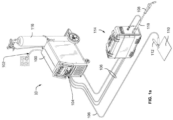
- FIG. 1a illustrates an exemplary welding-type system 10 including a welding power source 100.
- a source of power is provided to the welding power source 100 via an AC power cord 102.
- Typical ranges of AC power may be 115/230VAC or 208-575VAC, and may include single-phase or three-phase power.
- the welding power source 100 generally supplies power for the welding-type system 10.
- Weld output 104 provides welding output power via one or more weld cables 106 coupled to a modified welding torch 108 and a workpiece 110 using a clamp 112.
- Welding output power may be in the range of 10 Amps to 600 Amps or more, and range from 0 volts at short circuit to 44 volts or more into an open welding arc.
- Modern welding power sources and systems can provide welding-type power for various weld processes, which may include advanced waveform generation and control that is responsive to dynamic or static conditions at the welding arc.
- the illustrated welding-type system 10 includes a wire feeder 114 and a gas supply 116.
- the welding power source 100 may provide power and control to other equipment such as a wire feeder 114.
- the modified welding torch 108 is coupled to the wire feeder 114 via cable 118 in order to supply welding wire, shielding gas from the gas supply 116, and/or welding-type power to the welding torch 108 during operation of the welding-type system 10.
- the welding power source 100 may couple and/or directly supply welding-type power to the welding torch 108.
- the welding torch 108 is configured to preheat welding wire via polyphase electric arc preheating.
- the welding torch 108 contains three or more tungsten electrodes, which preheat the fed welding wire via arc wire heating.
- the three or more tungsten electrodes are connected to the welding power supply 100 to provide preheating power, and/or to a separate source of preheating power.
- the preheating power source (which may be the welding power supply 100) is configured to provide multi-phase power.
- the three electrodes are connected to three conductors which are connected to the three output phases of the preheating power source.
- the welding power source 100 may output welding-type power and also output three-phase heating power to the torch 108
- the three or more tungsten electrodes in the welding torch 108 may be connected to a dedicated polyphase preheating power source.
- the example welding-type system 10 of FIG. 1 has been described as a GMAW system, but the preheating system as disclosed can also be used, for example, to preheat Gas Tungsten Arc Welding ("GTAW") filler wire.
- GTAW Gas Tungsten Arc Welding
- the modified welding torch 108 may provide preheated welding filler wire for GTAW processes, flux-cored welding processes, metal-cored welding processes, submerged arc welding (SAW) processes, tandem welding processes, laser welding processes, hybrid welding processes, pulsed welding process, spray welding processes and/or any other processes involving adding wire filler metals.
- the preheating system may also be used to preheat wire electrode for deposition into a weld puddle in addition to conventional GMAW arc and electrode deposition, as a leading or trailing wire electrode deposition system.
- a die may be provided to curl preheated welding wire from the welding torch into a weld pool on the workpiece.
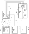
- FIG. 1b is a block diagram of the example welding system 10 of FIG 1a in which the system 10 includes a polyphase preheating power supply 130.
- the preheating power supply 130 is a three-phase power source which has three alternating current ("AC") outputs, output A 132, output B 134, and output C 136.
- Output A 132 is 120 degrees out of phase with output B 134 and output C 136
- output B 134 is 120 degrees of phase with output C 136.
- the three-phase power supply 130 is a regulated current power supply (e.g., the three-phase power supply 130 may be controlled to supply a consistent root mean square (“RMS”) current).
- RMS root mean square
- the AC outputs (132, 134, 136) operate at an RMS current between 1 and 100 Amps. In some examples, the RMS current may be less than 1 Amp. In some examples, the frequency of the AC outputs (132, 134, 136) is between 50 Hz and 20 kHz. High operating frequencies may be used to facilitate arc ignition and reignition and allows for lower operating currents.
- the preheating power supply 130 may be any power supply that is configured to provide a polyphase AC output at the desired frequency and current levels.
- Phase A 132 is connected via a conductor 138 to a first tungsten electrode 162 in the torch 108.
- Phase B 134 is connected via a conductor 140 to a second tungsten electrode 164 in the torch, and phase C 136 is connected via a conductor 142 to a third tungsten electrode 166 in the torch.
- the conductors 138, 140, and 142 connect to the torch 108 via the wire feeder 114.
- the conductors 138, 140, and 142 are included within the coupler 118, which also includes welding wire 152 fed by the wire feeder 114 from a welding wire source 150 as well as a power cable 106.
- Welding-type power provided by a welding-type power supply 100 is applied to the welding wire at the torch 108 via a contact tip 160.
- welding-type current arcs between the torch 108 and the workpiece 110, and the current returns from the workpiece 110 to the welding-type power supply 100 via a conductor 106.
- the contact tip 160 is closer to the torch tip 170 that the tungsten electrodes (162, 164, 166).
- the tungsten electrodes (162, 164, 166) are closer to the torch tip 170 that the contact tip 160.
- the three electrodes 162, 164, and 166 are physically arranged such that the electric arcs jump from an electrode (one of 162, 164, or 166) to the welding wire 152 and then to another electrode (one of 162, 164, or 166).
- the tungsten electrodes 162, 164, and 166 may be offset circumferentially by 120 degrees from each other and spaced along the length of the welding wire 152.
- a neutral line (not shown) is connected to the welding wire 152 (for example via the contact tip 160) and the preheating power supply 130 via a fourth conductor (not shown).
- a neutral conductor connects a fourth tungsten electrode to the preheating power supply 130.
- the preheating power supply 130 and the electrodes 162, 164, 166 may be configured in a delta configuration (e.g., without a neutral conductor) or in a Y configuration (e.g., using a neutral conductor).
- FIG. 2a shows an illustration of an isometric view of an example metal inert gas (“MIG") welding torch 200 configured to preheat welding wire.
- the welding torch 200 may implement the torch 108 of FIG. 1b .
- FIG. 2b shows a cross sectional view of the MIG welding torch 200.
- the handle of the MIG welding torch 200 is not shown in FIGs. 2a and 2b .
- the welding torch 200 includes a first tungsten electrode 202, a second tungsten electrode 204, and a third tungsten electrode 205 (which is not shown for ease of visibility).
- the first tungsten electrode 202 is connected to a first electric bus 206, and the second tungsten electrode 204 is connected to a second electric bus 208 (and the third tungsten electrode 205 is also connected to a third electric bus).
- the first electric bus 206 is connected to a power source (e.g., the power supply 130 of FIG. 1b ) via a first power cable 210, and the second electric bus is connected to a power source (e.g., the power supply 130 of FIG. 1b ) via a second power cable 212 (and the third electric bus is also connected to the power source).
- the welding torch 200 is supplied with shielding gas via shielding gas hose 214.
- the first tungsten electrode 202, the second tungsten electrode 204, and the third tungsten electrode 205 terminate in a chamber 216.
- the example chamber 216 is a ceramic tube, but may be another type of chamber configured to contain shielding gas adjacent the electrode wire traveling through the welding torch 200.
- the chamber 216 is supplied with shielding gas via the shielding gas hose 214.
- Welding wire is fed to the welding torch 200 via a wire liner 218.
- the wire liner 218 is connected to a connection block 220 via wire liner holder 222 and threaded wire liner holder 224.
- Fed welding wire enters a contact tip 226 from the wire liner 218, and then enters the chamber 216 via the contact tip 226.
- the contact tip 226 is connected to the connection block 220 via contact tip holder 228.
- the connection block 220 is connected to the preheating power source (e.g., the power supply 130 of FIG. 1b ) via a third power cable 230, which provides a neutral line for the preheating circuit.
- An insulator 232 insulates the connection block 220 from the first electric bus 206, the second electric bus 208, and the third electric bus.
- Preheated welding wire 238 exits the chamber 216 via a wire guide 234.
- Gas diffuser screens 236 diffuse shielding gas around the preheated welding wire 238 (e.g., the welding wire 152 of FIG. 1b ) that exits the chamber 216 via the wire guide 234.
- gas diffuser screen 236 diffuses shielding gas received from the chamber 216.
- gas diffuser screen is connected to a gas supply, for example gas supply 116 of FIG. 1a , via a dedicated shielding gas hose (not shown).
- the welding wire 152 is preheated inside the chamber 216 via electric arc preheating via arcs generated between the tungsten electrodes and the welding wire.
- Each tungsten electrode 202, 204 and 205 is connected to a separate phase of a polyphase (e.g., three-phase) preheating power source.
- preheating arcs may be between each tungsten electrode 202, 204, 205 and the welding wire.
- the welding wire is connected to a neutral line of the polyphase preheating power source.
- the contact tip 226 may be electrically coupled to a different terminal of the preheating power supply such that the tungsten electrode(s) 202, 204, 205, the arc(s), the welding wire, the contact tip 226, and the preheating power supply 130 form a preheating circuit (using appropriate electrical leads between the contact tip 226 and the preheating power supply 130 and between the tungsten electrode(s) 202, 204, 205 and the preheating power supply).
- FIG 3 illustrates an example preheating circuit, which may or may not include the contact tip 226.
- a separate neutral line is not used.
- the contact tip 226 may be connected to the preheating power source 130 as the neutral line and/or the electrodes 202, 204, 205 may be connected in a delta configuration without a neutral line.
- the distance between the tungsten electrodes (202, 204, and 205) and the welding wire is approximately 0.5 millimeters. In some examples, the positions of the tungsten electrodes 202, 204, and 205 are adjustable. In some examples, the arc gap is adjustable. In some examples, the distance between the tungsten electrodes 202, 204, and 205 and the welding wire is adjustable to accommodate different sizes of welding wire and/or to adjustments of the preheating arc voltage.
- Electrode positive polarity arc e.g., when the tungsten electrode (202, 204, or 205) has a positive voltage relative to the electrode wire
- Preheating aluminum welding wire with an electrode positive arc therefore removes the oxidation layer from the aluminum welding wire.
- the tungsten electrodes 202, 204 and 205 may be offset evenly circumferentially (e.g., each by 120 degrees from each other) in order to remove the oxide layer from all sides of the welding wire, as well as to evenly preheat the welding wire. In some examples, the tungsten electrodes 202, 204 and 205 may be evenly spaced around the circumference of the welding wire (e.g., each by 120 degrees from each other, plus or minus 30 degrees).
- the example chamber 216 is filled with shielding gas to prevent the re-oxidation of cleaned aluminum welding wire.
- the welding wire 238 may not be preheated inside of a chamber 216 (e.g., the preheating may be temporarily turned off or disabled).
- a nozzle may provide shielding gas to the preheated and cleaned aluminum welding wire to prevent the re-oxidation of the aluminum welding wire.
- the chamber 216 may include a nozzle portion (e.g., a taper at an end of the chamber 216 closest to the welding arc) to focus shielding gas flow toward the weld puddle.
- FIG. 3a is a block diagram of an exemplary electric arc preheating system 300, embodied, for example, in the welding torch 108 of FIG. 1b and 200 of FIGs. 2a and 2b .
- the preheating system 300 includes a first tungsten electrode 302 a second tungsten electrode 304, and a third tungsten electrode 306.
- the electrodes 302, 305, and 306 may implement the electrodes 162, 164, and 166 of FIG. 1b .
- the first tungsten electrode 302 is electrically connected to a first phase of the preheating power source 308, the second tungsten electrode 304 is electrically connected a second phase of the preheating power source 308, and the third tungsten electrode is electrically connected to a third phase of the preheating power source 308.
- the first, second, and third phases of the preheating power source 308 are 120 degrees out of phase with respect to each other.
- Welding wire 310 is fed through a contact tip 312 and delivered to a workpiece 314 via a wire guide 316.
- the contact tip 312 is electrically connected to a neutral line of the preheating power source 308.
- the contact tip is also electrically connected to a welding-type power source (not shown) in order to apply welding-type current to the welding wire 310.
- Welding wire 310 is preheated by electric arcs between the tungsten electrodes 302, 304, and 306 and the welding wire 310. At any given time, at least two arcs will exist between the electrodes 302, 304, and 306, and the wire 310.
- FIG. 3a shows the three arcs 322, 324, and 326, of which at least two will exist at any given time. The electric arcs 322, 324, and 326 jump from an electrode (302, 304, 306) to the welding wire 310 and then to another electrode (302, 304, 306).
- the two arcs (two of arcs 322, 324, and 326) that exist at any given time are in series, and therefore the total voltage drop across the arcs is equal to the sum of the voltage across each arc.
- using a three-phase system decreases the arc current by half while maintaining the same power level as compared to a preheating system which uses a single arc (e.g., between a single tungsten electrode and the wire 310).
- the tungsten electrodes 302, 304, and 306 are positioned between the contact tip 312 and the wire guide 316.
- the contact tip 312 may be closer to the wire guide 316 than the tungsten electrodes 302, 304, and 306.
- the electric arcs 322, 324, and 326 may occur inside of a chamber filled with shielding gas in order to prevent re-oxidation of the welding wire 310.
- FIG. 3b is an example scaled time plot 350 of the voltage at each electrode 302, 304, and 306 in a given cycle of the three phase power for.
- phase 1 is applied the first electrode 302
- phase 2 is applied to the second electrode 304
- phase 3 is applied to the third electrode 306.
- phase 1 connected to the first electrode 302 is commutating
- a first arc 326 exists from the third electrode 306 to the wire 310
- a second arc 324 exists from the wire 310 to the second electrode 304.
- Time T2 corresponds to the time when the phases of phase 1, phase 2, and phase 3, are 60 degrees in the periodic cycle.
- phase 3 connected to the third electrode 306 is commutating, a first arc 322 exists from the first electrode 302 to the wire 310, and a second arc 324 exists from the wire 310 to the second electrode 304.
- Time T3 corresponds to the time when the phases of phase 1, phase 2, and phase 3, are 120 degrees in the periodic cycle.
- phase 2 connected to the second electrode 304 is commutating, a first arc 322 exists from the first electrode 302 to the wire 310, and a second arc 326 exists from the wire 310 to the third electrode 306.
- Time T4 corresponds to the time when the phases of phase 1, phase 2, and phase 3, are 180 degrees in the periodic cycle.
- phase 1 connected to the first electrode 302 is commutating, a first arc 324 exists from the second electrode 304 to the wire 310, and a second arc 326 exists from the wire 310 to the third electrode 306.
- Time T5 corresponds to the time when the phases of phase 1, phase 2, and phase 3, are 240 degrees in the periodic cycle.
- phase 3 connected to the third electrode 306 is commutating, a first arc 324 exists from the second electrode 304 to the wire 310, and a second arc 322 exists from the wire 310 to the first electrode 302.
- Time T6 corresponds to the time when the phases of phase 1, phase 2, and phase 3, are 300 degrees in the periodic cycle.
- phase 2 connected to the second electrode 304 is commutating, a first arc 326 exists from the third electrode 306 to the wire 310, and a second arc 322 exists from the wire 310 to the first electrode 302.
- the power delivered to the wire 310 is the same (i.e., is uniform) across all time intervals.
- FIGs. 4a, 4b , 5a, and 5b illustrate views of example positioning of the preheating tungsten electrode(s) of the present disclosure.
- FIG. 4a shows a front view of a preheating system 400 using three preheating tungsten electrodes where each electrode is connected to a separate phase of a three-phase power supply.
- a first tungsten electrode 402, a second tungsten electrode 404, and a third tungsten electrode 406 are configured to preheat a welding wire 408.
- the first tungsten electrode 402, the second tungsten electrode 404, and the third tungsten electrode 406 are offset circumferentially (i.e. by 120 degrees) so as to evenly preheat the welding wire 408, as well as to evenly clean an aluminum welding wire 408.
- Preheating arcs occur between the three tungsten electrodes 402, 404, and 406, and the welding wire 408.
- An arc jumps from an electrode (402, 404, or 406) to the welding wire 408 and then to another electrode (402, 404, or 406).
- FIG. 4b shows that the tungsten electrodes 402, 404, and 406 are offset along the length of the welding wire 408.
- the tungsten electrodes 402, 404, and 406 are offset to ensure that the arcs jump from the electrodes (402, 404, or 406) to the welding wire 408 and then to another electrode (402, 404, or 406), rather than directly from electrode to electrode.
- FIG. 5a shows a front view of a preheating system 500 using four preheating tungsten electrodes where each electrode is connected to a separate phase of a four-phase power supply.
- a first tungsten electrode 502, a second tungsten electrode 504, a third tungsten electrode 506, and a fourth tungsten electrode 508 are configured to preheat a welding wire 510.
- the first tungsten electrode 502, the second tungsten electrode 504, the third tungsten electrode 506, and the fourth tungsten electrode 508 are offset circumferentially (i.e. by 90 degrees) so as to evenly preheat the welding wire 510, as well as to evenly clean an aluminum welding wire 510.
- Preheating arcs occur between the three tungsten electrodes 502, 504, 506, and 508, and the welding wire 510.
- An arc jumps from an electrode (502, 504, 506, or 508) to the welding wire 510 and then to another electrode (502, 504, 506, or 508).
- FIG. 5b shows that the tungsten electrodes 502, 504, 506, and 508 are offset along the length of the welding wire 510.
- the tungsten electrodes 502, 504, 506, and 508 are offset to ensure that the arcs jump from the electrodes (502, 504, 506, or 508) to the welding wire 510 and then to another electrode (502, 504, 506, or 508), rather than directly from electrode to electrode.
- Welding-type power supply and welding power source refers to any device capable of, when power is applied thereto, supplying welding, cladding, plasma cutting, induction heating, laser (including laser welding, laser hybrid, and laser cladding), carbon arc cutting or gouging and/or resistive preheating, including but not limited to transformer-rectifiers, inverters, converters, resonant power supplies, quasi-resonant power supplies, switch-mode power supplies, etc., as well as control circuitry and other ancillary circuitry associated therewith.
- Welding-type system includes any device capable of supplying power suitable for welding, plasma cutting, induction heating, CAC-A and/or hot wire welding/preheating (including laser welding and laser cladding), including inverters, converters, choppers, resonant power supplies, quasi-resonant power supplies, etc., as well as control circuitry and other ancillary circuitry associated therewith.
- Welding operation includes both actual welds (e.g., resulting in joining, such as welding or brazing) of two or more physical objects, an overlaying, texturing, and/or heat-treating of a physical object, and/or a cut of a physical object) and simulated or virtual welds (e.g., a visualization of a weld without a physical weld occurring).
- actual welds e.g., resulting in joining, such as welding or brazing
- simulated or virtual welds e.g., a visualization of a weld without a physical weld occurring.
- power is used throughout this specification for convenience, but also includes related measures such as energy, current, voltage, and enthalpy.
- controlling "power” may involve controlling voltage, current, energy, and/or enthalpy
- controlling based on “power” may involve controlling based on voltage, current, energy, and/or enthalpy.
- Electric power of the kind measured in watts as the product of voltage and current e.g., V*I power
- V*I power Electric power of the kind measured in watts as the product of voltage and current
- x and/or y means any element of the three-element set ⁇ (x), (y), (x, y) ⁇ . In other words, “x and/or y” means “one or both of x and y”.
- x, y, and/or z means any element of the seven-element set ⁇ (x), (y), (z), (x, y), (x, z), (y, z), (x, y, z) ⁇ . In other words, "x, y and/or z” means “one or more of x, y and z”.
- the term “exemplary” means serving as a non-limiting example, instance, or illustration.
- the terms “e.g.,” and “for example” set off lists of one or more non-limiting examples, instances, or illustrations.
Landscapes
- Engineering & Computer Science (AREA)
- Physics & Mathematics (AREA)
- Plasma & Fusion (AREA)
- Mechanical Engineering (AREA)
- Theoretical Computer Science (AREA)
- Arc Welding In General (AREA)
Claims (11)
- Vorrichtung zum Vorwärmen von Schweißdraht (152), wobei die Vorrichtung Folgendes aufweist:einen Eingang, der konfiguriert ist, Mehrphasenstrom zu empfangen;eine erste Wolframelektrode (162, 202), die über einen ersten Leiter (138, 206) mit dem Eingang verbunden ist, wobei der erste Leiter (138, 206) so konfiguriert ist, dass er eine erste Phase (132) des an dem Eingang empfangenen Mehrphasenstroms leitet;eine zweite Wolframelektrode (164, 204), die über einen zweiten Leiter (140, 208) mit dem Eingang verbunden ist, wobei der zweite Leiter (140, 208) so konfiguriert ist, dass er eine zweite Phase (134) des an dem Eingang empfangenen Mehrphasenstroms leitet;eine dritte Wolframelektrode (166, 205), die über einen dritten Leiter (142) mit dem Eingang verbunden ist, wobei der dritte Leiter (142) so konfiguriert ist, dass er eine dritte Phase (136) des an dem Eingang empfangenen Mehrphasenstroms leitet;einen ersten Bereich (216);eine Kontaktspitze (160, 226, 312), die so konfiguriert ist, dass sie den Schweißdraht (152) zum Vorwärmen dem ersten Bereich (216) zuführt;eine Drahtführung (234), die so konfiguriert ist, dass sie den vorgewärmten Schweißdraht (238) von dem ersten Bereich (216) zu einem Werkstück zuführt; undeinen Gasverbinder, der so konfiguriert ist, dass er Schutzgas an den ersten Bereich (216) um den vorgewärmten Schweißdraht (238), der dem Werkstück zugeführt wurde, herum abgibt;wobei die erste, die zweite und die dritte Elektrode so konfiguriert sind, dass sie Schweißdraht (152) über Lichtbogenvorwärmung vorwärmen, und wobei die Lichtbogenvorwärmung innerhalb des ersten Bereichs (216) erfolgt.
- Vorrichtung nach Anspruch 1, wobei der Mehrphasenstrom Dreiphasenstrom ist.
- Vorrichtung nach Anspruch 2, wobei die erste Wolframelektrode (162, 202) von der zweiten Wolframelektrode (164, 204) um einen Umfang des Schweißdrahts (152), der vorgewärmt wird, um 120 Grad versetzt ist, und die dritte Wolframelektrode (166, 205) in Umfangsrichtung von der zweiten Wolframelektrode (164, 204) um einen Umfang des Schweißdrahts (152) um 120 Grad versetzt ist, und wobei der Schweißdraht (152) im Allgemeinen zwischen die erste Wolframelektrode (162, 202), der zweiten Wolframelektrode (164, 204) und der dritten Wolframelektrode (166, 205) vorgeschoben wird, und
optional wobei die erste Wolframelektrode (162, 202) entlang einer Länge des Schweißdrahts (152) von der zweiten Wolframelektrode (164, 204) versetzt ist, die erste Wolframelektrode (162, 202) entlang einer Länge des Drahts (152) von der dritten Wolframelektrode (166, 205) versetzt ist und die zweite Wolframelektrode (164, 204) entlang einer Länge des Drahts (152) von der dritten Wolframelektrode (166, 205) versetzt ist. - Vorrichtung nach Anspruch 2, wobei, im Gebrauch, während einer Zeitdauer, in der Dreiphasenstrom an den Eingang angelegt wird, mindestens zwei Lichtbögen zwischen einem Schweißdraht (152) und mindestens zwei von der ersten Wolframelektrode (162, 202), der zweiten Wolframelektrode (164, 204) oder der dritten Wolframelektrode (166, 205) vorliegen.
- Vorrichtung nach Anspruch 1, wobei die erste Wolframelektrode (202), die zweite Wolframelektrode (204) und die dritte Wolframelektrode (205) ungefähr gleichmäßig um einen Umfang des Schweißdrahts (152), der vorgewärmt wird, beabstandet sind.
- Vorrichtung nach Anspruch 1, die ferner einen Neutralleiter aufweist, der elektrisch mit dem Schweißdraht (152) verbindbar ist und so konfiguriert ist, dass er über den Eingang mit einer Neutrallinie des Mehrphasenstroms verbunden ist.
- Vorrichtung nach Anspruch 1, wobei die Vorrichtung ein Brenner für Gas-Metall-Lichtbogenschweißen (GMAW) ist, und wobei die Kontaktspitze (160, 226) optional elektrisch mit dem Schweißdraht (152) und einer Schweißstromquelle (100) verbunden ist.
- Vorrichtung nach Anspruch 1, wobei der Mehrphasenstrom so konfiguriert ist, dass er eine geregelte Stromstärke bereitstellt.
- Vorrichtung nach Anspruch 1, wobei der Mehrphasenstrom so konfiguriert ist, dass er zwischen 50 und 20000 Hertz arbeitet.
- System zum Vorwärmen von Schweißdraht, wobei das System Folgendes aufweist:eine Mehrphasenstromquelle; unddadurch gekennzeichnet, dass das System eine Vorrichtung nach Anspruch 1 aufweist.
- System nach Anspruch 10, wobei der Mehrphasenstrom Dreiphasenstrom ist, und optional wobei die erste Wolframelektrode (162, 202) von der zweiten Wolframelektrode (165, 204) um einen Umfang des Schweißdrahts (152), der vorgewärmt wird, um 120 Grad versetzt ist, und die dritte Wolframelektrode (166, 205) in Umfangsrichtung von der zweiten Wolframelektrode (165, 204) um einen Umfang des Schweißdrahts (152) um 120 Grad versetzt ist, und wobei der Schweißdraht (152) im Allgemeinen zwischen die erste Wolframelektrode (162, 202), der zweiten Wolframelektrode (165, 204) und der dritten Wolframelektrode (166, 205) vorgeschoben wird.
Applications Claiming Priority (2)
| Application Number | Priority Date | Filing Date | Title |
|---|---|---|---|
| US201962892116P | 2019-08-27 | 2019-08-27 | |
| US16/936,070 US11745283B2 (en) | 2019-08-27 | 2020-07-22 | Methods for wire surface oxidation removal and/or wire preheating using polyphase electric arc preheating |
Publications (2)
| Publication Number | Publication Date |
|---|---|
| EP3799987A1 EP3799987A1 (de) | 2021-04-07 |
| EP3799987B1 true EP3799987B1 (de) | 2024-02-21 |
Family
ID=74681506
Family Applications (1)
| Application Number | Title | Priority Date | Filing Date |
|---|---|---|---|
| EP20192102.0A Active EP3799987B1 (de) | 2019-08-27 | 2020-08-21 | Vorrichtung und system zur drahtvorwärmung unter verwendung von mehrphasen-lichtbogenvorwärmung |
Country Status (3)
| Country | Link |
|---|---|
| US (1) | US11745283B2 (de) |
| EP (1) | EP3799987B1 (de) |
| CN (1) | CN112439983B (de) |
Families Citing this family (3)
| Publication number | Priority date | Publication date | Assignee | Title |
|---|---|---|---|---|
| US12202084B2 (en) | 2021-03-22 | 2025-01-21 | Lincoln Global, Inc. | Electrode metal preheating for arc start improvement |
| CN119897652A (zh) * | 2025-04-02 | 2025-04-29 | 格陆博科技有限公司 | 一种制动器生产加工用组装焊接装置 |
| CN120055543B (zh) * | 2025-04-28 | 2025-08-08 | 成都航空职业技术学院 | 一种钛合金焊接用高功率激光-空心钨极复合焊炬 |
Citations (1)
| Publication number | Priority date | Publication date | Assignee | Title |
|---|---|---|---|---|
| EP2666041B1 (de) * | 2011-01-19 | 2015-06-17 | 3SAE Technologies, Inc. | Mehrstufiges faserverarbeitungssystem und verfahren |
Family Cites Families (29)
| Publication number | Priority date | Publication date | Assignee | Title |
|---|---|---|---|---|
| US3274371A (en) * | 1965-06-01 | 1966-09-20 | Union Carbide Corp | Method of depositing metal |
| US4013867A (en) * | 1975-08-11 | 1977-03-22 | Westinghouse Electric Corporation | Polyphase arc heater system |
| JPS62207583A (ja) | 1986-03-10 | 1987-09-11 | Chiyoda Chem Eng & Constr Co Ltd | ホツトワイヤtig溶接法 |
| JP2837681B2 (ja) * | 1988-12-29 | 1998-12-16 | 亮拿 佐藤 | セラミックス製造用多相・多電極アーク炉 |
| JP3451791B2 (ja) * | 1995-05-25 | 2003-09-29 | 石川島播磨重工業株式会社 | アーク分割ワイヤ加熱装置 |
| NL1015649C1 (nl) * | 2000-07-07 | 2002-01-08 | Brabander Wilhelmus Antonius Joha | Lastoorts. |
| CN1285439C (zh) * | 2004-06-30 | 2006-11-22 | 哈尔滨工业大学 | 阴极雾化式铝合金焊丝焊前清理设备 |
| CN100335223C (zh) | 2005-04-26 | 2007-09-05 | 哈尔滨工业大学 | 氩弧预热焊丝的方法 |
| US9028158B2 (en) * | 2007-02-07 | 2015-05-12 | 3Sae Technologies, Inc. | Multi-stage fiber processing system and method |
| CN201134972Y (zh) * | 2007-11-30 | 2008-10-15 | 中国航天空气动力技术研究院 | 一种交流等离子电弧加热器 |
| CN201249331Y (zh) * | 2008-08-28 | 2009-06-03 | 宝山钢铁股份有限公司 | 加热温度自调节控制的激光热丝焊送丝装置 |
| JP5400696B2 (ja) * | 2010-04-26 | 2014-01-29 | 株式会社神戸製鋼所 | 消耗電極式ガスシールドアーク溶接方法および消耗電極式ガスシールドアーク溶接システム |
| CN102000903B (zh) | 2010-10-27 | 2012-07-11 | 哈尔滨工业大学 | Tig电源辅助的双tig复合热源焊接设备及方法 |
| CN102528243A (zh) | 2011-12-15 | 2012-07-04 | 哈尔滨工业大学 | 钛-铝异种合金tig电弧预热的电弧熔钎焊焊接方法 |
| JP5926589B2 (ja) * | 2012-01-10 | 2016-05-25 | 株式会社ダイヘン | プラズマミグ溶接方法 |
| US20140008354A1 (en) | 2012-07-06 | 2014-01-09 | Lincoln Global, Inc. | Method and system of using induction heating to heat consumable during hot wire process |
| JP2014176890A (ja) * | 2013-03-15 | 2014-09-25 | Daihen Corp | 溶接トーチおよびアーク溶接システム |
| US9937580B2 (en) | 2014-01-24 | 2018-04-10 | Lincoln Global, Inc. | Method and system for additive manufacturing using high energy source and hot-wire |
| US10675699B2 (en) | 2015-12-10 | 2020-06-09 | Illinois Tool Works Inc. | Systems, methods, and apparatus to preheat welding wire |
| US12194579B2 (en) | 2015-12-10 | 2025-01-14 | Illinois Tool Works Inc. | Systems, methods, and apparatus to preheat welding wire |
| PL3265263T3 (pl) | 2016-02-23 | 2019-06-28 | Fronius International Gmbh | Urządzenie spawalnicze z laserowym urządzeniem do wstępnego podgrzewania drutu dodatkowego |
| JP6552469B2 (ja) * | 2016-10-17 | 2019-07-31 | 福伸工業株式会社 | プラズマ発生装置及び方法並びにこれらを用いた微粒子製造装置及び方法 |
| CN206455281U (zh) * | 2016-12-14 | 2017-09-01 | 江苏阿斯美特精工科技有限公司 | 一种同轴多钨极共熔池tig焊装置及其焊枪 |
| WO2018227196A1 (en) * | 2017-06-09 | 2018-12-13 | Illinois Tool Works Inc. | Welding torch, with two contact tips and a plurality of liquid cooling assemblies for conducting currents to the contact tips |
| EP3634684B1 (de) | 2017-06-09 | 2022-10-05 | Illinois Tool Works Inc. | Schweissbrenner mit erster kontaktspitze zum vorwärmen von schweissdraht und einer zweiten kontaktspitze |
| CN107297561B (zh) * | 2017-06-22 | 2019-09-03 | 北京工业大学 | 一种热丝焊接设备 |
| CN107186323A (zh) * | 2017-07-21 | 2017-09-22 | 哈尔滨工业大学 | 用于热丝tig焊接的焊丝加热装置 |
| WO2019087386A1 (ja) * | 2017-11-06 | 2019-05-09 | Primetals Technologies Japan株式会社 | 溶接装置および溶接方法 |
| CN108581156A (zh) * | 2018-06-19 | 2018-09-28 | 哈尔滨工程大学 | 基于中心热丝的双钨极等离子弧焊接装置与焊接方法 |
-
2020
- 2020-07-22 US US16/936,070 patent/US11745283B2/en active Active
- 2020-08-21 EP EP20192102.0A patent/EP3799987B1/de active Active
- 2020-08-26 CN CN202010871102.6A patent/CN112439983B/zh active Active
Patent Citations (1)
| Publication number | Priority date | Publication date | Assignee | Title |
|---|---|---|---|---|
| EP2666041B1 (de) * | 2011-01-19 | 2015-06-17 | 3SAE Technologies, Inc. | Mehrstufiges faserverarbeitungssystem und verfahren |
Also Published As
| Publication number | Publication date |
|---|---|
| US20210060684A1 (en) | 2021-03-04 |
| CN112439983A (zh) | 2021-03-05 |
| US11745283B2 (en) | 2023-09-05 |
| CN112439983B (zh) | 2025-07-18 |
| EP3799987A1 (de) | 2021-04-07 |
Similar Documents
| Publication | Publication Date | Title |
|---|---|---|
| US3549857A (en) | Welding processes and apparatus | |
| EP2379271B1 (de) | Doppeldraht-gmaw-schweissbrenneranordnung und verfahren | |
| EP3799987B1 (de) | Vorrichtung und system zur drahtvorwärmung unter verwendung von mehrphasen-lichtbogenvorwärmung | |
| CN110621434A (zh) | 预热焊丝的系统和方法 | |
| EP3612338B1 (de) | Systeme und verfahren zur bereitstellung von schutz vor heizspannungrückführungsverlust | |
| CA3078063C (en) | Methods and apparatus to provide welding-type power and preheating power | |
| US11446756B2 (en) | Systems and methods for wire surface oxidation removal and/or wire preheating using a tungsten arc | |
| US20240342821A1 (en) | Systems and methods for gas control during welding wire pretreatments | |
| EP3838468B1 (de) | Verfahren und systeme zur gassteuerung bei schweissdrahtvorbehandlungen | |
| US11897062B2 (en) | Systems, methods, and apparatus to preheat welding wire | |
| US12240064B2 (en) | Methods and apparatus to provide welding-type power and preheating power | |
| EP4112216B1 (de) | Systeme und verfahren zum starten eines schweissverfahrens | |
| JPS5812108B2 (ja) | 熱イオン化ガス内で溶接する方法および溶接ト−チ |
Legal Events
| Date | Code | Title | Description |
|---|---|---|---|
| PUAI | Public reference made under article 153(3) epc to a published international application that has entered the european phase |
Free format text: ORIGINAL CODE: 0009012 |
|
| STAA | Information on the status of an ep patent application or granted ep patent |
Free format text: STATUS: THE APPLICATION HAS BEEN PUBLISHED |
|
| AK | Designated contracting states |
Kind code of ref document: A1 Designated state(s): AL AT BE BG CH CY CZ DE DK EE ES FI FR GB GR HR HU IE IS IT LI LT LU LV MC MK MT NL NO PL PT RO RS SE SI SK SM TR |
|
| AX | Request for extension of the european patent |
Extension state: BA ME |
|
| STAA | Information on the status of an ep patent application or granted ep patent |
Free format text: STATUS: REQUEST FOR EXAMINATION WAS MADE |
|
| 17P | Request for examination filed |
Effective date: 20210920 |
|
| RBV | Designated contracting states (corrected) |
Designated state(s): AL AT BE BG CH CY CZ DE DK EE ES FI FR GB GR HR HU IE IS IT LI LT LU LV MC MK MT NL NO PL PT RO RS SE SI SK SM TR |
|
| STAA | Information on the status of an ep patent application or granted ep patent |
Free format text: STATUS: EXAMINATION IS IN PROGRESS |
|
| 17Q | First examination report despatched |
Effective date: 20220211 |
|
| GRAP | Despatch of communication of intention to grant a patent |
Free format text: ORIGINAL CODE: EPIDOSNIGR1 |
|
| STAA | Information on the status of an ep patent application or granted ep patent |
Free format text: STATUS: GRANT OF PATENT IS INTENDED |
|
| INTG | Intention to grant announced |
Effective date: 20230818 |
|
| RIN1 | Information on inventor provided before grant (corrected) |
Inventor name: HOEGER, MICHAEL V. |
|
| GRAJ | Information related to disapproval of communication of intention to grant by the applicant or resumption of examination proceedings by the epo deleted |
Free format text: ORIGINAL CODE: EPIDOSDIGR1 |
|
| STAA | Information on the status of an ep patent application or granted ep patent |
Free format text: STATUS: EXAMINATION IS IN PROGRESS |
|
| GRAP | Despatch of communication of intention to grant a patent |
Free format text: ORIGINAL CODE: EPIDOSNIGR1 |
|
| STAA | Information on the status of an ep patent application or granted ep patent |
Free format text: STATUS: GRANT OF PATENT IS INTENDED |
|
| INTC | Intention to grant announced (deleted) | ||
| INTG | Intention to grant announced |
Effective date: 20231018 |
|
| P01 | Opt-out of the competence of the unified patent court (upc) registered |
Effective date: 20231124 |
|
| GRAS | Grant fee paid |
Free format text: ORIGINAL CODE: EPIDOSNIGR3 |
|
| GRAA | (expected) grant |
Free format text: ORIGINAL CODE: 0009210 |
|
| STAA | Information on the status of an ep patent application or granted ep patent |
Free format text: STATUS: THE PATENT HAS BEEN GRANTED |
|
| AK | Designated contracting states |
Kind code of ref document: B1 Designated state(s): AL AT BE BG CH CY CZ DE DK EE ES FI FR GB GR HR HU IE IS IT LI LT LU LV MC MK MT NL NO PL PT RO RS SE SI SK SM TR |
|
| REG | Reference to a national code |
Ref country code: GB Ref legal event code: FG4D |
|
| REG | Reference to a national code |
Ref country code: CH Ref legal event code: EP |
|
| REG | Reference to a national code |
Ref country code: DE Ref legal event code: R096 Ref document number: 602020025947 Country of ref document: DE |
|
| REG | Reference to a national code |
Ref country code: IE Ref legal event code: FG4D |
|
| REG | Reference to a national code |
Ref country code: LT Ref legal event code: MG9D |
|
| REG | Reference to a national code |
Ref country code: NL Ref legal event code: MP Effective date: 20240221 |
|
| PG25 | Lapsed in a contracting state [announced via postgrant information from national office to epo] |
Ref country code: IS Free format text: LAPSE BECAUSE OF FAILURE TO SUBMIT A TRANSLATION OF THE DESCRIPTION OR TO PAY THE FEE WITHIN THE PRESCRIBED TIME-LIMIT Effective date: 20240621 |
|
| PG25 | Lapsed in a contracting state [announced via postgrant information from national office to epo] |
Ref country code: LT Free format text: LAPSE BECAUSE OF FAILURE TO SUBMIT A TRANSLATION OF THE DESCRIPTION OR TO PAY THE FEE WITHIN THE PRESCRIBED TIME-LIMIT Effective date: 20240221 |
|
| PG25 | Lapsed in a contracting state [announced via postgrant information from national office to epo] |
Ref country code: GR Free format text: LAPSE BECAUSE OF FAILURE TO SUBMIT A TRANSLATION OF THE DESCRIPTION OR TO PAY THE FEE WITHIN THE PRESCRIBED TIME-LIMIT Effective date: 20240522 |
|
| REG | Reference to a national code |
Ref country code: AT Ref legal event code: MK05 Ref document number: 1658707 Country of ref document: AT Kind code of ref document: T Effective date: 20240221 |
|
| PG25 | Lapsed in a contracting state [announced via postgrant information from national office to epo] |
Ref country code: RS Free format text: LAPSE BECAUSE OF FAILURE TO SUBMIT A TRANSLATION OF THE DESCRIPTION OR TO PAY THE FEE WITHIN THE PRESCRIBED TIME-LIMIT Effective date: 20240521 Ref country code: NL Free format text: LAPSE BECAUSE OF FAILURE TO SUBMIT A TRANSLATION OF THE DESCRIPTION OR TO PAY THE FEE WITHIN THE PRESCRIBED TIME-LIMIT Effective date: 20240221 Ref country code: HR Free format text: LAPSE BECAUSE OF FAILURE TO SUBMIT A TRANSLATION OF THE DESCRIPTION OR TO PAY THE FEE WITHIN THE PRESCRIBED TIME-LIMIT Effective date: 20240221 |
|
| PG25 | Lapsed in a contracting state [announced via postgrant information from national office to epo] |
Ref country code: ES Free format text: LAPSE BECAUSE OF FAILURE TO SUBMIT A TRANSLATION OF THE DESCRIPTION OR TO PAY THE FEE WITHIN THE PRESCRIBED TIME-LIMIT Effective date: 20240221 |
|
| PG25 | Lapsed in a contracting state [announced via postgrant information from national office to epo] |
Ref country code: AT Free format text: LAPSE BECAUSE OF FAILURE TO SUBMIT A TRANSLATION OF THE DESCRIPTION OR TO PAY THE FEE WITHIN THE PRESCRIBED TIME-LIMIT Effective date: 20240221 |
|
| PG25 | Lapsed in a contracting state [announced via postgrant information from national office to epo] |
Ref country code: RS Free format text: LAPSE BECAUSE OF FAILURE TO SUBMIT A TRANSLATION OF THE DESCRIPTION OR TO PAY THE FEE WITHIN THE PRESCRIBED TIME-LIMIT Effective date: 20240521 Ref country code: NO Free format text: LAPSE BECAUSE OF FAILURE TO SUBMIT A TRANSLATION OF THE DESCRIPTION OR TO PAY THE FEE WITHIN THE PRESCRIBED TIME-LIMIT Effective date: 20240521 Ref country code: NL Free format text: LAPSE BECAUSE OF FAILURE TO SUBMIT A TRANSLATION OF THE DESCRIPTION OR TO PAY THE FEE WITHIN THE PRESCRIBED TIME-LIMIT Effective date: 20240221 Ref country code: LT Free format text: LAPSE BECAUSE OF FAILURE TO SUBMIT A TRANSLATION OF THE DESCRIPTION OR TO PAY THE FEE WITHIN THE PRESCRIBED TIME-LIMIT Effective date: 20240221 Ref country code: IS Free format text: LAPSE BECAUSE OF FAILURE TO SUBMIT A TRANSLATION OF THE DESCRIPTION OR TO PAY THE FEE WITHIN THE PRESCRIBED TIME-LIMIT Effective date: 20240621 Ref country code: HR Free format text: LAPSE BECAUSE OF FAILURE TO SUBMIT A TRANSLATION OF THE DESCRIPTION OR TO PAY THE FEE WITHIN THE PRESCRIBED TIME-LIMIT Effective date: 20240221 Ref country code: GR Free format text: LAPSE BECAUSE OF FAILURE TO SUBMIT A TRANSLATION OF THE DESCRIPTION OR TO PAY THE FEE WITHIN THE PRESCRIBED TIME-LIMIT Effective date: 20240522 Ref country code: FI Free format text: LAPSE BECAUSE OF FAILURE TO SUBMIT A TRANSLATION OF THE DESCRIPTION OR TO PAY THE FEE WITHIN THE PRESCRIBED TIME-LIMIT Effective date: 20240221 Ref country code: ES Free format text: LAPSE BECAUSE OF FAILURE TO SUBMIT A TRANSLATION OF THE DESCRIPTION OR TO PAY THE FEE WITHIN THE PRESCRIBED TIME-LIMIT Effective date: 20240221 Ref country code: BG Free format text: LAPSE BECAUSE OF FAILURE TO SUBMIT A TRANSLATION OF THE DESCRIPTION OR TO PAY THE FEE WITHIN THE PRESCRIBED TIME-LIMIT Effective date: 20240221 Ref country code: AT Free format text: LAPSE BECAUSE OF FAILURE TO SUBMIT A TRANSLATION OF THE DESCRIPTION OR TO PAY THE FEE WITHIN THE PRESCRIBED TIME-LIMIT Effective date: 20240221 |
|
| PG25 | Lapsed in a contracting state [announced via postgrant information from national office to epo] |
Ref country code: PT Free format text: LAPSE BECAUSE OF FAILURE TO SUBMIT A TRANSLATION OF THE DESCRIPTION OR TO PAY THE FEE WITHIN THE PRESCRIBED TIME-LIMIT Effective date: 20240621 Ref country code: PL Free format text: LAPSE BECAUSE OF FAILURE TO SUBMIT A TRANSLATION OF THE DESCRIPTION OR TO PAY THE FEE WITHIN THE PRESCRIBED TIME-LIMIT Effective date: 20240221 |
|
| PG25 | Lapsed in a contracting state [announced via postgrant information from national office to epo] |
Ref country code: SE Free format text: LAPSE BECAUSE OF FAILURE TO SUBMIT A TRANSLATION OF THE DESCRIPTION OR TO PAY THE FEE WITHIN THE PRESCRIBED TIME-LIMIT Effective date: 20240221 Ref country code: PT Free format text: LAPSE BECAUSE OF FAILURE TO SUBMIT A TRANSLATION OF THE DESCRIPTION OR TO PAY THE FEE WITHIN THE PRESCRIBED TIME-LIMIT Effective date: 20240621 Ref country code: PL Free format text: LAPSE BECAUSE OF FAILURE TO SUBMIT A TRANSLATION OF THE DESCRIPTION OR TO PAY THE FEE WITHIN THE PRESCRIBED TIME-LIMIT Effective date: 20240221 Ref country code: LV Free format text: LAPSE BECAUSE OF FAILURE TO SUBMIT A TRANSLATION OF THE DESCRIPTION OR TO PAY THE FEE WITHIN THE PRESCRIBED TIME-LIMIT Effective date: 20240221 |
|
| PG25 | Lapsed in a contracting state [announced via postgrant information from national office to epo] |
Ref country code: DK Free format text: LAPSE BECAUSE OF FAILURE TO SUBMIT A TRANSLATION OF THE DESCRIPTION OR TO PAY THE FEE WITHIN THE PRESCRIBED TIME-LIMIT Effective date: 20240221 |
|
| PG25 | Lapsed in a contracting state [announced via postgrant information from national office to epo] |
Ref country code: SM Free format text: LAPSE BECAUSE OF FAILURE TO SUBMIT A TRANSLATION OF THE DESCRIPTION OR TO PAY THE FEE WITHIN THE PRESCRIBED TIME-LIMIT Effective date: 20240221 |
|
| PG25 | Lapsed in a contracting state [announced via postgrant information from national office to epo] |
Ref country code: EE Free format text: LAPSE BECAUSE OF FAILURE TO SUBMIT A TRANSLATION OF THE DESCRIPTION OR TO PAY THE FEE WITHIN THE PRESCRIBED TIME-LIMIT Effective date: 20240221 Ref country code: CZ Free format text: LAPSE BECAUSE OF FAILURE TO SUBMIT A TRANSLATION OF THE DESCRIPTION OR TO PAY THE FEE WITHIN THE PRESCRIBED TIME-LIMIT Effective date: 20240221 |
|
| PG25 | Lapsed in a contracting state [announced via postgrant information from national office to epo] |
Ref country code: SK Free format text: LAPSE BECAUSE OF FAILURE TO SUBMIT A TRANSLATION OF THE DESCRIPTION OR TO PAY THE FEE WITHIN THE PRESCRIBED TIME-LIMIT Effective date: 20240221 |
|
| PG25 | Lapsed in a contracting state [announced via postgrant information from national office to epo] |
Ref country code: SM Free format text: LAPSE BECAUSE OF FAILURE TO SUBMIT A TRANSLATION OF THE DESCRIPTION OR TO PAY THE FEE WITHIN THE PRESCRIBED TIME-LIMIT Effective date: 20240221 Ref country code: SK Free format text: LAPSE BECAUSE OF FAILURE TO SUBMIT A TRANSLATION OF THE DESCRIPTION OR TO PAY THE FEE WITHIN THE PRESCRIBED TIME-LIMIT Effective date: 20240221 Ref country code: RO Free format text: LAPSE BECAUSE OF FAILURE TO SUBMIT A TRANSLATION OF THE DESCRIPTION OR TO PAY THE FEE WITHIN THE PRESCRIBED TIME-LIMIT Effective date: 20240221 Ref country code: EE Free format text: LAPSE BECAUSE OF FAILURE TO SUBMIT A TRANSLATION OF THE DESCRIPTION OR TO PAY THE FEE WITHIN THE PRESCRIBED TIME-LIMIT Effective date: 20240221 Ref country code: DK Free format text: LAPSE BECAUSE OF FAILURE TO SUBMIT A TRANSLATION OF THE DESCRIPTION OR TO PAY THE FEE WITHIN THE PRESCRIBED TIME-LIMIT Effective date: 20240221 Ref country code: CZ Free format text: LAPSE BECAUSE OF FAILURE TO SUBMIT A TRANSLATION OF THE DESCRIPTION OR TO PAY THE FEE WITHIN THE PRESCRIBED TIME-LIMIT Effective date: 20240221 |
|
| REG | Reference to a national code |
Ref country code: DE Ref legal event code: R097 Ref document number: 602020025947 Country of ref document: DE |
|
| PG25 | Lapsed in a contracting state [announced via postgrant information from national office to epo] |
Ref country code: IT Free format text: LAPSE BECAUSE OF FAILURE TO SUBMIT A TRANSLATION OF THE DESCRIPTION OR TO PAY THE FEE WITHIN THE PRESCRIBED TIME-LIMIT Effective date: 20240221 |
|
| PLBE | No opposition filed within time limit |
Free format text: ORIGINAL CODE: 0009261 |
|
| STAA | Information on the status of an ep patent application or granted ep patent |
Free format text: STATUS: NO OPPOSITION FILED WITHIN TIME LIMIT |
|
| PG25 | Lapsed in a contracting state [announced via postgrant information from national office to epo] |
Ref country code: IT Free format text: LAPSE BECAUSE OF FAILURE TO SUBMIT A TRANSLATION OF THE DESCRIPTION OR TO PAY THE FEE WITHIN THE PRESCRIBED TIME-LIMIT Effective date: 20240221 |
|
| 26N | No opposition filed |
Effective date: 20241122 |
|
| REG | Reference to a national code |
Ref country code: CH Ref legal event code: PL |
|
| PG25 | Lapsed in a contracting state [announced via postgrant information from national office to epo] |
Ref country code: LU Free format text: LAPSE BECAUSE OF NON-PAYMENT OF DUE FEES Effective date: 20240821 |
|
| GBPC | Gb: european patent ceased through non-payment of renewal fee |
Effective date: 20240821 |
|
| PG25 | Lapsed in a contracting state [announced via postgrant information from national office to epo] |
Ref country code: SI Free format text: LAPSE BECAUSE OF FAILURE TO SUBMIT A TRANSLATION OF THE DESCRIPTION OR TO PAY THE FEE WITHIN THE PRESCRIBED TIME-LIMIT Effective date: 20240221 Ref country code: MC Free format text: LAPSE BECAUSE OF FAILURE TO SUBMIT A TRANSLATION OF THE DESCRIPTION OR TO PAY THE FEE WITHIN THE PRESCRIBED TIME-LIMIT Effective date: 20240221 Ref country code: CH Free format text: LAPSE BECAUSE OF NON-PAYMENT OF DUE FEES Effective date: 20240831 |
|
| REG | Reference to a national code |
Ref country code: BE Ref legal event code: MM Effective date: 20240831 |
|
| PG25 | Lapsed in a contracting state [announced via postgrant information from national office to epo] |
Ref country code: GB Free format text: LAPSE BECAUSE OF NON-PAYMENT OF DUE FEES Effective date: 20240821 |
|
| PG25 | Lapsed in a contracting state [announced via postgrant information from national office to epo] |
Ref country code: BE Free format text: LAPSE BECAUSE OF NON-PAYMENT OF DUE FEES Effective date: 20240831 |
|
| PG25 | Lapsed in a contracting state [announced via postgrant information from national office to epo] |
Ref country code: FR Free format text: LAPSE BECAUSE OF NON-PAYMENT OF DUE FEES Effective date: 20240831 |
|
| PG25 | Lapsed in a contracting state [announced via postgrant information from national office to epo] |
Ref country code: IE Free format text: LAPSE BECAUSE OF NON-PAYMENT OF DUE FEES Effective date: 20240821 |
|
| PGFP | Annual fee paid to national office [announced via postgrant information from national office to epo] |
Ref country code: DE Payment date: 20250827 Year of fee payment: 6 |
|
| PG25 | Lapsed in a contracting state [announced via postgrant information from national office to epo] |
Ref country code: CY Free format text: LAPSE BECAUSE OF FAILURE TO SUBMIT A TRANSLATION OF THE DESCRIPTION OR TO PAY THE FEE WITHIN THE PRESCRIBED TIME-LIMIT; INVALID AB INITIO Effective date: 20200821 |
|
| PG25 | Lapsed in a contracting state [announced via postgrant information from national office to epo] |
Ref country code: HU Free format text: LAPSE BECAUSE OF FAILURE TO SUBMIT A TRANSLATION OF THE DESCRIPTION OR TO PAY THE FEE WITHIN THE PRESCRIBED TIME-LIMIT; INVALID AB INITIO Effective date: 20200821 |