EP3838468B1 - Verfahren und systeme zur gassteuerung bei schweissdrahtvorbehandlungen - Google Patents
Verfahren und systeme zur gassteuerung bei schweissdrahtvorbehandlungen Download PDFInfo
- Publication number
- EP3838468B1 EP3838468B1 EP20213486.2A EP20213486A EP3838468B1 EP 3838468 B1 EP3838468 B1 EP 3838468B1 EP 20213486 A EP20213486 A EP 20213486A EP 3838468 B1 EP3838468 B1 EP 3838468B1
- Authority
- EP
- European Patent Office
- Prior art keywords
- wire
- gas
- welding
- chamber
- electrode
- Prior art date
- Legal status (The legal status is an assumption and is not a legal conclusion. Google has not performed a legal analysis and makes no representation as to the accuracy of the status listed.)
- Active
Links
Images


Classifications
-
- B—PERFORMING OPERATIONS; TRANSPORTING
- B23—MACHINE TOOLS; METAL-WORKING NOT OTHERWISE PROVIDED FOR
- B23K—SOLDERING OR UNSOLDERING; WELDING; CLADDING OR PLATING BY SOLDERING OR WELDING; CUTTING BY APPLYING HEAT LOCALLY, e.g. FLAME CUTTING; WORKING BY LASER BEAM
- B23K9/00—Arc welding or cutting
- B23K9/12—Automatic feeding or moving of electrodes or work for spot or seam welding or cutting
- B23K9/133—Means for feeding electrodes, e.g. drums, rolls, motors
-
- B—PERFORMING OPERATIONS; TRANSPORTING
- B23—MACHINE TOOLS; METAL-WORKING NOT OTHERWISE PROVIDED FOR
- B23K—SOLDERING OR UNSOLDERING; WELDING; CLADDING OR PLATING BY SOLDERING OR WELDING; CUTTING BY APPLYING HEAT LOCALLY, e.g. FLAME CUTTING; WORKING BY LASER BEAM
- B23K9/00—Arc welding or cutting
- B23K9/235—Preliminary treatment
-
- B—PERFORMING OPERATIONS; TRANSPORTING
- B23—MACHINE TOOLS; METAL-WORKING NOT OTHERWISE PROVIDED FOR
- B23K—SOLDERING OR UNSOLDERING; WELDING; CLADDING OR PLATING BY SOLDERING OR WELDING; CUTTING BY APPLYING HEAT LOCALLY, e.g. FLAME CUTTING; WORKING BY LASER BEAM
- B23K9/00—Arc welding or cutting
- B23K9/10—Other electric circuits therefor; Protective circuits; Remote controls
- B23K9/1093—Consumable electrode or filler wire preheat circuits
-
- B—PERFORMING OPERATIONS; TRANSPORTING
- B23—MACHINE TOOLS; METAL-WORKING NOT OTHERWISE PROVIDED FOR
- B23K—SOLDERING OR UNSOLDERING; WELDING; CLADDING OR PLATING BY SOLDERING OR WELDING; CUTTING BY APPLYING HEAT LOCALLY, e.g. FLAME CUTTING; WORKING BY LASER BEAM
- B23K9/00—Arc welding or cutting
- B23K9/16—Arc welding or cutting making use of shielding gas
- B23K9/173—Arc welding or cutting making use of shielding gas and of a consumable electrode
-
- B—PERFORMING OPERATIONS; TRANSPORTING
- B23—MACHINE TOOLS; METAL-WORKING NOT OTHERWISE PROVIDED FOR
- B23K—SOLDERING OR UNSOLDERING; WELDING; CLADDING OR PLATING BY SOLDERING OR WELDING; CUTTING BY APPLYING HEAT LOCALLY, e.g. FLAME CUTTING; WORKING BY LASER BEAM
- B23K9/00—Arc welding or cutting
- B23K9/24—Features related to electrodes
- B23K9/26—Accessories for electrodes, e.g. ignition tips
-
- B—PERFORMING OPERATIONS; TRANSPORTING
- B23—MACHINE TOOLS; METAL-WORKING NOT OTHERWISE PROVIDED FOR
- B23K—SOLDERING OR UNSOLDERING; WELDING; CLADDING OR PLATING BY SOLDERING OR WELDING; CUTTING BY APPLYING HEAT LOCALLY, e.g. FLAME CUTTING; WORKING BY LASER BEAM
- B23K9/00—Arc welding or cutting
- B23K9/32—Accessories
-
- B—PERFORMING OPERATIONS; TRANSPORTING
- B23—MACHINE TOOLS; METAL-WORKING NOT OTHERWISE PROVIDED FOR
- B23K—SOLDERING OR UNSOLDERING; WELDING; CLADDING OR PLATING BY SOLDERING OR WELDING; CUTTING BY APPLYING HEAT LOCALLY, e.g. FLAME CUTTING; WORKING BY LASER BEAM
- B23K35/00—Rods, electrodes, materials, or media, for use in soldering, welding, or cutting
-
- B—PERFORMING OPERATIONS; TRANSPORTING
- B23—MACHINE TOOLS; METAL-WORKING NOT OTHERWISE PROVIDED FOR
- B23K—SOLDERING OR UNSOLDERING; WELDING; CLADDING OR PLATING BY SOLDERING OR WELDING; CUTTING BY APPLYING HEAT LOCALLY, e.g. FLAME CUTTING; WORKING BY LASER BEAM
- B23K9/00—Arc welding or cutting
- B23K9/24—Features related to electrodes
- B23K9/28—Supporting devices for electrodes
- B23K9/29—Supporting devices adapted for making use of shielding means
- B23K9/291—Supporting devices adapted for making use of shielding means the shielding means being a gas
- B23K9/295—Supporting devices adapted for making use of shielding means the shielding means being a gas using consumable wire electrodes
Definitions
- This disclosure relates generally to welding and, more particularly, to methods, systems, and apparatuses for pre-treating a wire of a welding implement to reduce the amount of hydrogen in solidified welds and to make such welds less susceptible to hydrogen induced cracking (HIC) and hydrogen embrittlement. More specifically, this disclosure relates to methods, systems, and apparatuses for controlling and utilizing gas flow during such pre-treating operations.
- HIC hydrogen induced cracking
- Welding is a process that has increasingly become ubiquitous in all industries. Welding is, at its core, simply a way of bonding two pieces of metal. A wide range of welding systems and welding control regimes have been implemented for various purposes.
- MIG metal inert gas
- SAW submerged arc welding
- Such wire feeding systems are available for other welding systems, such as tungsten inert gas (TIG) welding. Electrical power is applied to the welding wire and a circuit is completed through the workpiece to sustain a welding arc that melts the electrode wire and the workpiece to form the desired weld.
- US-2836701-A discloses a method of gas-shielded metal arc welding in which the electrode is heated away from the arc zone to dehydrogenate the electrode.
- JP-S60130475-A discloses a MIG welding method in which a welding wire is heated by a heat source and receives electricity from an electrode chip, by which air shielded arc welding is accomplished in a gaseous argon atmosphere.
- the vapor of the moisture adsorbed on the wire and the evaporating hydrogen molecules generated as a result of heating by the heat source are delivered to an outside part by gaseous argon admitted into the introducing part of the chip, by which the intrusion thereof into the arc weld zone is prevented.
- a first aspect of the present invention defines a method of removing hydrogen from a filler wire that is utilized in a welding operation according to claim 1.
- a second aspect of the present invention defines a welding system according to claim 7, comprising a torch having a distal end, through which a filler wire extends.
- the filler wire passes into and through the torch in a downstream direction toward the distal end.
- the pre-treatment chamber surrounds at least a portion of the wire and the shielding gas chamber surrounds at least a portion of the wire.
- the shielding gas chamber has a gas inlet and a gas outlet.
- the outlet of the shielding gas chamber is configured such that the shielding gas exiting the shielding gas chamber flows around the portion of the wire that extends from the distal end of the torch.
- the outlet of the shielding gas chamber may generally correspond with the distal end of the torch.
- the pre-treatment chamber also comprises a gas inlet and a gas outlet. The gas outlet of the pre-treatment chamber, however, is isolated from the shielding gas chamber.
- the gas outlet of the pre-treating chamber is configured so that the gas exiting the pre-treatment chamber is directed away from the weld pool, i.e. away from the portion of the wire extending from the distal end of the torch. This may involve venting the gas from the pre-treatment chamber to the atmosphere at a distance from the distal end of the torch and in a direction different from the downstream flow direction of the shielding gas. Alternatively, the gas exiting the pre-treatment chamber may be transported to a collection unit, recycled, or the like.
- the gas outlet of the pre-treatment chamber is isolated from the shielding gas chamber by the pre-treatment chamber being at least partially nested within at least a portion of the shielding gas chamber.
- the gas outlet of the pre-treating chamber may include one or more bypass ducts extending through the shielding gas chamber. In this way, the spent pre-treatment gas may be transported through the shielding gas chamber without the spent pre-treatment gas mixing with the shielding gas.
- the gas outlet of the pre-treatment chamber is isolated from the shielding gas chamber by the pre-treatment chamber being positioned upstream of the shielding gas chamber. The downstream end of the pre-treatment chamber may be separated from the upstream end of the shielding gas chamber by one or more baffles and/or by any other equipment which may serve to fluidly isolate the two chambers.
- the pre-treatment chamber and the shielding gas chamber may both be positioned within a body of the torch.
- the gas inlet of the pre-treatment chamber and the inlet of the shielding gas chamber may be operatively connected, e.g. fluidly connected, such that a gas line attached to a single connection port can supply gas to both chambers. In this way, a single gas supply may be used as both the pre-treatment gas and the shielding gas.
- the gas inlet of the pre-treatment chamber and the inlet of the shielding gas chamber may be distinct from one another, such that the gas supplied to the pre-treatment chamber may be of a different composition than the gas supplied to the shielding gas chamber.
- the gas inlet of the pre-treatment chamber may be configured to be connected to a first gas line and the inlet of the shielding gas chamber may be configured to be connected to a second gas line.
- the system may be configured so that a user may select whether to use a single gas attachment or two separate gas attachments.
- the pre-treatment chamber may be configured to resistively pre-heat an electrode wire, such as through a wire pre-heating circuit.
- the wire pre-heating circuit may comprise a first contact tip, a second contact tip, and a section of the electrode wire between the first and second contact tips.
- the pre-treatment chamber may be configured to etch a filler wire, such as an aluminum wire.
- the pre-treatment chamber may comprise one or more electrodes, e.g. tungsten electrodes, arranged and configured to etch a surface layer of the filler wire.
- the gas flowing through the pre-treatment chamber may be caused to have a Reynolds number of at least 2100, alternatively at least 2500, alternatively at least 2800, alternatively at least 3000, alternatively at least 3500, alternatively at least 4000.
- the gas flowing through the pre-treatment chamber may be acted upon in order to bring about a desired degree of turbulence by in any number of ways, including for example impinging the flow of gas at or near a gas inlet of the pre-treatment chamber, such as by flowing the gas through an area of decreased cross-section, placing one or more obstructions within the flow-path of the gas, passing the gas past one or more roughened or textured surfaces, or the like.
- the treating of the wire involves pre-heating the wire to remove hydrogen and/or other contaminants.
- the pre-heating may involve a resistive pre-heating, in which a wire pre-heating circuit is created.
- the wire pre-heating circuit may include the connection of first and second contact tips to the wire in a spaced apart relationship.
- the treating of the wire involves etching the surface of a wire, e.g. etching the surface of an aluminum wire, to remove hydrogen and/or other contaminants.
- the etching may involve the use of one or more electrodes, e.g. tungsten electrodes.
- Hydrogen embrittlement is a process by which metals lose toughness, become brittle, and/or fracture due to the presence and diffusion of hydrogen.
- the pressure on the workpiece caused at least in part by hydrogen introduced by a filler wire such as welding electrodes, can build up.
- the pressure exceeds a threshold level the workpiece can crack in a mechanism referred to as hydrogen-induced cracking.
- metals can pick up hydrogen through the usage of welding filler materials which have been exposed to moisture and/or otherwise forming hydrocarbons.
- Tubular welding wire generally provide more difficulties than solid welding wire in controlling the level of moisture during manufacture, and may have more tendency to pick up moisture during storage and/or field use.
- an operator and/or other material handling personnel must take extra care to avoid submitting filler material to sources which can increase risk of hydrogen cracking.
- Common seamed wires which are often used in applications such as shipbuilding, pipelines, and/or structural welding, which can be susceptible to hydrogen cracking include FabCO XI,550 (E71T-1CJ/-9CJ/-12CJ H4), Fabshield 81N1 (E71T8-Ni1 J H8), and FabCOR 86R (E70C-6M H4).
- Aluminum welding wire is highly reactive, and forms a surface oxide layer when exposed to atmospheric conditions.
- the oxide layer contains significant amounts of water from atmospheric humidity. The water provides a source of hydrogen, which can cause porosity in an aluminum weld.
- the welding systems described herein may form a weld (e.g., at a weld joint) between two components in a weldment by any known electric welding techniques.
- Known electric welding techniques include, inter alia, shielded metal arc welding (SMAW), MIG, flux-cored arc welding (FCAW), TIG, laser welding, sub-arc welding (SAW), stud welding, friction stir welding, and resistance welding.
- SMAW shielded metal arc welding
- MIG shielded metal arc welding
- FCAW flux-cored arc welding
- TIG laser welding
- SAW sub-arc welding
- stud welding stud welding
- friction stir welding and resistance welding.
- MIG, TIG, hot wire cladding, hot wire TIG, hot wire brazing, multiple arc applications, and SAW welding techniques, inter alia, may involve automated or semi-automated external metal filler (e.g., via a wire feeder).
- the welding equipment may be arc welding equipment having one or more power supplies, and associated circuitry, that provides a direct current (DC), alternating current (AC), or a combination thereof to an electrode wire of a welding tool.
- the welding tool may be, for example, a TIG torch, a MIG torch, or a flux cored torch (commonly called a MIG "gun").
- the electrode wire may be tubular-type electrode, a solid type wire, a flux-core wire, a seamless metal core wire, and/or any other type of electrode wire.
- a wire-fed welding system refers to a system capable of performing welding (e.g., gas metal arc welding (GMAW), gas tungsten arc welding (GTAW), submerged arc welding (SAW), etc.), brazing, cladding, hardfacing, and/or other processes, in which a filler metal is provided by a wire that is fed to a work location, such as an arc or weld puddle.
- welding e.g., gas metal arc welding (GMAW), gas tungsten arc welding (GTAW), submerged arc welding (SAW), etc.
- GMAW gas metal arc welding
- GTAW gas tungsten arc welding
- SAW submerged arc welding
- Embodiments of the present disclosure are directed to pretreatment of a welding wire, i.e., treatment of a filler wire in the travel path of the wire and prior to a welding arc and/or deposition.
- the pretreatment may include preheating, etching, or a combination thereof.
- preheating refers to heating a wire prior to a welding arc and/or deposition.
- etching refers to the removal of a surface layer of a wire, e.g. the removal of an oxide layer of an aluminum wire.
- the pretreatment may take place within a welding tool itself, e.g. within a torch or gun, or within a separate component, e.g. within a component that is independent of the welding tool. Because the pretreatment releases hydrogen from the wire, the pretreatment takes place in what is referred to herein as a cleaning chamber or a pre-cleaning chamber.
- Disclosed examples involve resistively preheating the electrode wire after unwinding from the wire spool and prior to the arc.
- the electrode wire may be preheated via contact points located at any two points between the wire source and the arc.
- the contact points may be implemented using any technique to establish electrical contact with the electrode wire, such as contact tips, conductive brushes, and/or conductive rollers.
- Some other disclosed examples involve resistively preheating the wire during the wire drawing (e.g., manufacturing) process to immediately reduce the hydrogen in the drawn wire.
- Disclosed examples therefore are capable of delivering wire to welding applications that substantially reduce risks of cracking and embrittlement in welds that use the preheated wire.
- Disclosed examples include one or more preheating circuits in addition to a welding circuit, which are controlled to provide current to preheat the electrode.
- Preheating a welding electrode provides a number of potential benefits, which are described in U.S. Patent Application No. 15/343,992, filed November 4, 2016 , and entitled "Systems, Methods, and Apparatus to Preheat Welding Wire.”
- disclosed examples use one or more preheating circuits to reduce the hydrogen content in a welding wire by increasing the rate of hydrogen diffusion from the wire.
- the preheating circuit includes multiple contact points (e.g., welding torch contact tips, and/or other contact points), which may be positioned in contact with the electrode wire at the welding torch, at a wire feeder, between the wire feeder and the welding torch, and/or any combination of the welding torch, the wire feeder, or between the welding torch and the wire feeder.
- a welding system includes multiple preheating circuits. Different preheating circuits may provide different levels of preheating current. For example, the electrode wire fed from a wire spool may be provided with a first, low preheating current to increase the temperature of the wire to encourage hydrogen diffusion, while maintaining sufficient column strength for feeding the wire without buckling.
- a higher preheating current is applied to increase the wire temperature closer to a melting point of the wire.
- the currents applied by each of the preheating circuits may be superimposed (e.g., additive or subtractive) in section(s) of the electrode wire, superimposed (e.g., additive or subtractive) at one or more contact tips or other contact points, or non-overlapping. Additionally or alternatively, the welding current may be superimposed on one or more preheating currents and/or non-overlapping with the preheating current(s).
- Disclosed examples control the preheating current in the wire via control loops (e.g., voltage-controlled loops, current-controlled loops, etc.) to reduce the level of hydrogen in a consistent manner over a relatively short period of time compared to conventional baking and compared to conventional extended stickout techniques.
- the preheating current is controlled based on aspects of the wire such as wire type, wire composition, and/or wire diameter, a length of the wire path from the wire feeder to the arc, wire feed speed, and/or any other control variables affecting hydrogen diffusion.
- a look-up table can be implemented to recall optimum preheat parameters for certain types of tubular wire and wire feed rate.
- a hydrogen sensor may be added to monitor the level of hydrogen.
- Palladium (Pd) based e.g., Pd-functionalized) carbon nanotube (CNT), a diode-based Schottky sensor with Pd-alloy gate, and/or a highly-ordered vertically oriented titanium dioxide (TiO2) nanotube microelectromechanical systems (MEMS) sensors can be incorporated in the welding torch to detect hydrogen levels and/or perform closed loop control of the preheat power source.
- a hydrogen sensor may also be placed near the preheat chamber as a measure of hydrogen level before depositing the consumable electrode into weld pool to form the weld metal.
- Some example apparatus further include an electrode preheating control circuit configured to control the preheating current based on at least one of a type of the welding-type electrode, a chemistry of the welding-type electrode, a wire diameter, or a gas composition.
- Some example apparatus further include a hydrogen sensor configured to measure hydrogen at least one of in the welding-type electrode or proximate the welding-type electrode, in which the electrode preheating control circuit is configured to control the preheating current based on a hydrogen measurement from the hydrogen sensor.
- the hydrogen sensor is at least one of a Palladium-based sensor, a diode-based Schottky sensor, or a micromechanical systems-based sensor.
- Some example apparatus further include a moisture sensor configured to measure moisture at least one of in the welding-type electrode or proximate the welding-type electrode, in which the electrode preheating control circuit is configured to control the preheating current based on a moisture measurement from the moisture sensor.
- the electrode preheating circuit is configured to provide the preheating current to the electrode preheating circuit via the first contact point and a second contact point.
- the preheating current and the welding-type current have respective polarities that reduce a net current at the second contact point to less than the preheating current and the welding-type current.
- Some example apparatus further include a wire cooler configured to cool the welding-type electrode following heating of the welding-type electrode.
- Some example apparatus further include an electrode preheating control circuit configured to control the preheating current to achieve at least one of a target current, a target voltage, a target power, a target resistance, a target temperature, or a target enthalpy in the welding-type electrode.
- the welding torch includes a vent system to remove hydrogen from a volume proximate the welding-type electrode conducting the preheating current.
- the electrode preheating circuit includes a second contact point located between the first contact point and the wire source.
- the second contact point is a drive roll of a wire feeder.
- the second contact point comprises a second contact tip in the welding torch.
- the electrode preheating circuit includes the first contact point and the second contact point.
- the electrode preheating circuit includes a third contact point located between the first contact point and the second contact point.
- Disclosed example methods to reduce hydrogen in a welding-type electrode include: providing, via a welding-type power source, welding-type current to a welding-type circuit, in which the welding-type circuit includes a welding-type electrode and a first contact point of a welding torch; and supplying, via an electrode preheating circuit, preheating current through a first portion of the welding-type electrode between a wire source of the welding-type electrode and the first contact point of the welding torch.
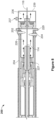
- FIG. 1 illustrates a functional diagram of an exemplary welding system 200 having a resistive pre-heat.
- the welding system 200 may comprise a torch body 204, a shielding gas inlet 206, a first contact tip 218, a ceramic guide 214, a gas nozzle 216, and a second contact tip 208.
- first contact tip 218 and/or the second contact tip 208 are modular and/or removable so as to be easily serviceable by a user of the welding system 200.
- first contact tip 218 and/or the second contact tip 208 may be implemented as replaceable cartridges.
- the welding equipment 110 monitors and indicates that the first contact tip 218 and/or the second contact tip 208 should be replaced, taking into account, for instance, measurements of the used time of the first contact tip 218 and/or the second contact tip 208, temperature(s) of the first contact tip 218 and/or the second contact tip 208, amperage in the first contact tip 218 and/or the second contact tip 208 and/or the wire, voltage between the first contact tip 218 and/or the second contact tip 208 and/or the wire, enthalpy in the wire, and/or any other data.
- the electrode wire 114 passes into the body of the torch 204 through a first contact tip 218 and a second contact tip 208, between which a second power supply 202b generates a preheat current to heat the electrode wire 114.
- the preheat current may enter the electrode wire 114 via the second contact tip 208 and exit via the first contact tip 218.
- a welding current may also enter the electrode wire 114.
- the welding current is generated, or otherwise provided by, a first power supply 202a.
- the welding current exits the electrode wire 114 via the workpiece 106, which in turn generates the welding arc 220. That is, the electrode wire 114, when energized for welding via a welding current, carries a high electrical potential.
- the electrode wire 114 makes contact with a target metal workpiece 106, an electrical circuit is completed and the welding current flows through the electrode wire 114, across the metal work piece(s) 106, and to ground.
- the welding current causes the electrode wire 114 and the parent metal of the work piece(s) 106 in contact with the electrode wire 114 to melt, thereby joining the work pieces as the melt solidifies.
- a welding arc 220 may be generated with drastically reduced arc energy.
- the preheat current can range from, for example, 25 A to 400 A.
- the preheat current is inversely proportional to the square root of the distance between the two contact tips and/or directly proportional to the electrode wire 114 size for a given rise in electrode temperature. That is, the smaller the distance, the more current needed to achieve a certain temperature rise.
- the preheat current may flow in either direction between the contact tips 208, 218.
- a guide 214 may be provided to guide the electrode wire 114 as it travels from the second contact tip 208 to the first contact tip 218.
- the guide 214 may be fabricated from ceramic, a dielectric material, a glass-ceramic polycrystalline material, and/or another non-conductive material.
- the contact tip assembly 200 may further comprise a spring-loaded device, or equivalent device, that reduces wire kinking, buckling, and jamming, while increasing wire contact efficiency by keeping the electrode wire 114 taught and/or straight.
- both the first contact tip 218 and the second contact tip 208 are present within the body 204 of a welding torch. In other embodiments, however, one or more of the second contact tip 208 and the first contact tip 218 may be positioned at a different location, e.g. outside the body 204 of a welding torch.
- the second contact tip 208 may be positioned at the wire feeder (e.g., at welding equipment 110) or another extended distance, to introduce the preheat current, in which case the preheat current may exit a contact tip in the torch 204.
- the contact tip in the torch 204 may be the same, or different, from the contact tip where the welding current is introduced to the electrode wire 114.
- the preheat contact tip(s) may be further positioned along the electrode wire 114 to facilitate use with Push-Pull Guns, such as those available from Miller Electric of Appleton, Wisconsin.
- the liner could be made from ceramic rollers so the preheat current could be injected back at the feeder and be a very low value due to the length of the liner.
- the first contact tip 218 and a second contact tip 208 may be positioned on each side of a gooseneck bend.
- a preheat section may be curved (e.g., non-straight). That is, wire is fed through a section of the torch that has a bend greater than 0 degrees or a neck that would be considered a "gooseneck".
- the second contact tip 208 may be positioned before the initial bend and the first contact tip 218 after the bend is complete.
- Such an arrangement may add the benefit to the connectivity of the heated wire moving through the portion of the neck between the two contact tips. Such an arrangement results in a more reliable connection between the two contact tips where an off axis, machined dielectric insert was previously needed.
- the welding current is generated, or otherwise provided by, a first power supply 202a
- the preheat current is generated, or otherwise provided by, a second power supply 202b.
- the first power supply 202a and the second power supply 202b may ultimately share a common power source (e.g., a common generator or line current connection), but the current from the common power source is converted, inverted, and/or regulated to yield the two separate currents - the preheat current and the welding current.
- the preheat operation may be facilitated with a single power source and associated converter circuitry. In which case, three leads may extend from the welding equipment 110 or an auxiliary power line in the welder, which could eliminate the need for the second power supply 202b.
- the preheat current and welding current may be DC, AC, pulsed DC, and/or a combination thereof.
- the welding current may be AC, while the preheat current may be DC, or vice versa.
- the welding current may be DC electrode negative (DCEN) or a variety of other power schemes.
- the welding current waveform may be further controlled, including constant voltage, constant current, and/or pulsed (e.g., AccuPulse).
- constant voltage and/or constant power, constant penetration, and/or constant enthalpy may be used to facilitate preheat instead of constant current. For example, it may be desirable to control the amount of penetration into the workpiece.
- the penetration/heat input can be advantageously controlled.
- penetration can be changed to reflect a desired weld bead/penetration profile.
- the preheat current may be changed into a plurality of waveforms, such as, but not limited to, a pulse type waveform to achieve the desired weld bead/penetration profile.
- the current could be line frequency AC delivered from a simple transformer with primary phase control. Controlling the current and voltage delivered to the preheat section may be simpler using a CC, CV, or constant power depending on how the control is implemented as well as the power supply configuration to do it.
- the welding power source for consumable arc welding may include regulating a constant welding current output and adapt wire speed to maintain arc length or arc voltage set-point (e.g., CC+V process control).
- the welding power source may include regulating a constant welding voltage output (or arc length) and adapt wire speed to maintain arc current set-point (e.g., CV+C process control).
- the CC+V and CV+C process controls allow for accommodation of wire stick-out variation and pre-heat current/temperature variation by adapting wire feed speed (or variable deposition).
- the power source may include regulating a constant welding current output, the feeder maintains constant deposition, and the pre-heat power source adapts preheat current (or pre-heat power) to maintain constant arc voltage (or arc length).
- pre-heat current/power adds a new degree of freedom to the wire welding processes (GMAW and SAW) that allows flexibility and controllability in maintaining constant weld penetration and weld width (arc current), deposition (wire speed) and process stability (arc length or voltage).
- the welding system 200 may be configured to monitor the exit temperature of the electrode wire 114 between the preheat contact tips (e.g., the preheat temperature), as illustrated, between the first contact tip 218 and the second contact tip 208.
- the preheat temperature may be monitored using one or more temperature determining devices, such as a thermometer, positioned adjacent the electrode wire 114, or otherwise operably positioned, to facilitate periodic or real-time feedback.
- Example thermometers may include both contact sensors and non-contact sensors, such as non-contact infrared temperature sensors, thermistors, and/or thermocouples. An infrared thermometer determines temperature from a portion of the thermal radiation emitted by the electrode wire 114 to yield a measured preheat temperature.
- the temperature determining device may, in addition to or in lieu of the thermometers, comprise one or more sensors and/or algorithms that calculate the preheat temperature of the electrode wire 114.
- the system may dynamically calculate temperature based on, for example, a current or voltage.
- the thermometer may measure the temperature of the dielectric guide or first contact tip to infer the wire temperature.
- the operator may set a target predetermined preheat temperature whereby the welding system 200 dynamically monitors the preheat temperature of the electrode wire 114 and adjusts the preheat current via the second power supply 102b to compensate for any deviation (or other difference) of the measured preheat temperature from the target predetermined preheat temperature.
- controls may be set such that a welding operation cannot be performed until the electrode wire 114 has been preheated to the predetermined preheat temperature.
- the example assembly 200 preheats a section of the electrode wire 114 to reduce the presence of hydrogen in the electrode wire 114 prior to welding.
- the assembly 200 may monitor hydrogen levels in the electrode wire 114 and preheat a section of the electrode wire 114 to reduce hydrogen prior to welding.
- the assembly 200 includes an electrode preheating control circuit 222.
- the electrode preheating control circuit 222 is operable to control the preheating power supplied by the power supply 202b to maintain a substantially constant heat input to a weld (e.g., a heat input within a range).
- the electrode preheating control circuit 222 controls the preheating power based on estimating the stickout heating of the electrode wire 114 and by modifying the preheating power provided by the power supply 202b based on changes in the estimated stickout heating.
- the electrode preheating control circuit 222 receives a hydrogen measurement signal from a hydrogen sensor and adjusts the preheat parameters (e.g., current, voltage, power, enthalpy, etc.) of the preheating power supply 202b and/or the welding parameters of the welding power supply 202a.
- preheat parameters e.g., current, voltage, power, enthalpy, etc.
- the assembly 200 By preheating the electrode wire 114 to a desired temperature at speed at which the electrode wire 114 is feeding out of the assembly 200, relative to the amount of hydrogen present or allowable, the assembly 200 more easily reduces and/or eliminates excess hydrogen than conventional methods of hydrogen reduction.
- the electrode preheating control circuit 222 controls the preheat parameters, such as preheat power, current, voltage and/or joule heating, based on observed baking effectiveness for the type of electrode wire to reduce moisture in the type of electrode wire, and based on the feed speed of the electrode wire 114. For instance, a higher feed rate of the electrode wire 114 may require higher preheat power. Welding with tubular electrodes on butt seams may require less preheat power than tubular electrodes with a joggle joint. Larger diameter tubular wire with more cross-sectional area may require higher preheat power.
- preheat power such as preheat power, current, voltage and/or joule heating
- the example electrode preheating control circuit 222 may use a look-up table or other memory structure to retrieve preheat parameters based on inputs to the electrode preheating control circuit 222 (e.g., via a user interface or another input method). For example, the electrode preheating control circuit 222 may use a wire feed speed, a wire type (e.g., tubular wire, solid wire, a wire name, etc.), and/or a wire diameter, to identify in the table one or more of a preheating current, a preheating voltage, a preheating enthalpy, a wire temperature, and/or a wire resistance (e.g., indicative of the temperature of the wire) to be used to control the preheating power supply 202b.
- a wire feed speed e.g., a wire type (e.g., tubular wire, solid wire, a wire name, etc.), and/or a wire diameter, to identify in the table one or more of a preheating current, a preheating
- the wire type may be identified, for example, using a model number, universal product code (UPC), and/or any a physical description of the wire.
- the resistance of the wire may also be included as a variable for determining the preheat.
- the sheath thickness of a tubular wire and/or a fill percentage e.g., the ratio of core material weight to sheath weight
- the preheating distance may be an input, fixed, and/or dynamically controllable and, therefore, may be used as an input variable for the look-up table.
- the data in the look-up tables may be determined empirically by testing different wire types to determine hydrogen content using different resistive heating levels and/or time periods.
- a hydrogen sensor monitors the level of hydrogen on and/or proximate to the electrode wire 114.
- the hydrogen sensor may be a Palladium (Pd) based sensor such as a Palladium-functionalized carbon nanotube (CNT).
- Pd Palladium
- CNT Palladium-functionalized carbon nanotube
- Another example implementation of the hydrogen sensor is as a diode-based Schottky sensor with a Pd-alloy gate.
- highly-ordered vertically oriented titanium dioxide (TiO2) nanotube microelectromechanical systems (MEMS) sensors may be incorporated in the welding torch to detect low levels (e.g., in parts per million, parts per billion, etc.) of hydrogen in or proximate to the electrode wire 114.
- TiO2 titanium dioxide
- MEMS microelectromechanical systems
- the electrode preheating control circuit 222 may perform closed-loop control of the preheating power supply 202b based on the hydrogen measurement received from the hydrogen sensor.
- a hydrogen sensor may also be placed near a preheat chamber as a measure of hydrogen level before depositing the electrode wire 114 into the weld pool at the workpiece 106 to form the weld metal.
- a moisture sensor may be used instead of or as a complement to the hydrogen sensor.
- the example assembly 200 allows a tubular electrode to be produced at low cost and yet achieve low hydrogen performance.
- the assembly 200 may also reduce the cost of reducing or preventing hydrogen pick up during production of the electrode wire 114, such as the costs associated with strip steel quality, drawing lube, flux sourcing and storage, and/or other production, storage and/or procurement costs can be minimized.
- the cost of packaging and/or storage against moisture pick up in the electrode wire 114 can be reduced and the shelf life of the electrode wire 114 can be extended.
- the preheat hydrogen reduction method further eliminates the need to pre-bake the electrode wire 114 for a significant period of time before using the wire 114.
- the preheat hydrogen reduction method can heat the electrode wire 114 more than possible when using a traditional extended stickout method, further reducing hydrogen levels prior to introduction to the weld than conventional methods.
- an electrical arc(s) can be used to remove the oxide layer of aluminum welding wire.
- Aluminum is highly reactive, and forms a surface oxide layer when exposed to atmospheric conditions.
- the oxide layer contains significant amounts of water from atmospheric humidity. The water provides a source of hydrogen, which can cause porosity in an aluminum weld. Therefore, it is advantageous to remove the oxide layer, and to reduce or prevent the re-formation of the oxide layer after cleaning.
- disclosed systems and methods may be configured to remove the oxide layer of aluminum welding wire (as well as any other surface contaminant) via electric arc preheating of the wire. Gas is flowed across the wire during the etching process in order to prevent the re-formation of the oxide layer on the aluminum welding wire.
- the disclosed systems and methods may be configured to remove organic contaminants from welding wire during the preheating process. Removing organic contaminants prevents weld defects caused by "dirty" welding wire, which can include porosity in the weld.
- Disclosed examples involve etching the wire after unwinding from the wire spool and prior to the arc.
- the wire may be etched via an electric arc, e.g. formed by one or more tungsten electrodes, located at any points between the wire source and the arc.
- Etching a welding wire provides a number of potential benefits, which are described in U.S. Patent Application No. 16/553,522, filed August 28, 2019 , and entitled "Systems and Methods for Wire Surface Oxidation Removal and/or Wire Preheating Using a Tungsten Arc".
- the system may be configured to etch a welding wire via electric arc preheating.
- the system contains one or more tungsten electrodes which preheat the fed welding wire via arc wire heating.
- the one or more tungsten electrodes may be connected to the welding power supply to provide preheating power and/or to a separate source of preheating power.
- the one or more tungsten electrodes in the welding torch may be connected to one or more dedicated preheating power sources.
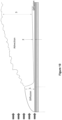
- FIG. 2 is a block diagram of an exemplary electric arc preheating system 1000 such as may be used for etching an aluminum wire.
- Preheating system 1000 includes a first tungsten electrode 1002 and a second tungsten electrode 1004. Each tungsten electrode 1002 and 1006 is electrically connected to the preheating power source 1006.
- the preheating power source 1006 is also a welding power source which provides welding power which provides power for a welding arc 1008 between welding wire 1010 and a workpiece 1012.
- one or more of tungsten electrodes 1002 and 1006 may instead be electrically connected to one or more dedicated preheating power sources.
- Welding wire 1010 is fed through a contact tip 1014 and delivered to a workpiece 1012.
- the contact tip 1014 is connected to the welding power source 1006 in order to provide power for a welding arc 1008 between the welding wire 1010 and the workpiece 1012.
- the workpiece 1012 is electrically connected to the power source 1006 in order to complete a circuit between the power source 1006, the contact tip 1014, and the welding wire 1010.
- the welding wire 1010 is preheated by an electric arc 1016 between the first tungsten electrode 1002 and the second tungsten electrode 1004 through which the welding wire 1010 passes.
- the electric arc 1016 includes a first arc from the first tungsten electrode 1002 to the welding wire 1010, and a second arc from the welding wire 1010 to the second tungsten electrode 1004, or vice versa.
- the tungsten electrodes 1002 and 1004 are positioned after the contact tip 1014 (i.e., the welding wire 1010 is preheated and etched downstream from the contact tip 1014). In other embodiments, however, the tungsten electrodes 1002 and 1004 may be positioned before the contact tip 1014 (i.e., the welding wire 1010 is preheated and etched upstream from the contact tip 1014).
- the first tungsten electrode 1002 and the second tungsten electrode 1004 may be offset circumferentially (i.e. by 180 degrees) so as to etch both sides of an aluminum welding wire 1010.
- the system 1000 may comprise greater than two electrodes.
- the system 1000 may further comprise a third tungsten electrode.
- the first tungsten electrode, the second tungsten electrode, and the third tungsten electrode may be offset circumferentially (i.e. by 120 degrees) so as to evenly etch an aluminum welding wire 1010.
- the system 1000 may further comprise a fourth tungsten electrode.
- the first tungsten electrode, the second tungsten electrode, the third tungsten electrode, and the fourth tungsten electrode may be offset circumferentially (i.e. by 90 degrees) so as to evenly etch an aluminum welding wire 1010.
- one or both of the tungsten electrodes may be set to be electrode positive.
- Arcs using electrode positive polarity e.g., the tungsten electrodes have a positive voltage relative to the electrode wire
- Preheating aluminum welding wire with an electrode positive arc therefore removes the oxidation layer from the aluminum welding wire.
- the electrodes may be connected to alternating current power sources. When connected to alternating current power sources, the electric arc(s) between the tungsten electrodes will have a positive component, and the positive component removes the surface oxidation of aluminum welding wire.
- tungsten electrodes can be connected to a power source with a positive time component.
- the preheating system may be connected to a polyphase power source (e.g., three electrodes are connected to the three phases of a three-phase power source). Since polyphase systems utilize alternating current, when polyphase systems are utilized, at any given time at least one arc is electrode positive, which facilitates removal of contaminants from aluminum welding wire
- a gas flow may be provided around the wire 114.
- this gas may be referred to herein as a pre-heating gas, regardless of whether the pre-treatment involves pre-heating, etching, or both.
- the shielding gas used in the welding operation is capable as operating as the pre-heating gas, the shielding gas for the welding operation has previously been used as the pre-heating gas.
- the shielding gas inlet 206 is positioned upstream of at least a portion of the pre-heating zone, e.g. upstream of the first contact tip 218.
- the shielding gas inlet 206 is positioned upstream of at least a portion of the pre-heating zone, e.g. upstream of the first contact tip 218.
- Embodiments of the present disclosure provide methods and systems by which the pre-treating gas can be separated from the shielding gas, such that the shielding gas that is directed toward the welding arc 220 does not contain hydrogen contaminants from the pre-treating step.
- Embodiments of the present disclosure thereby provide a multiple flowpaths for the shielding gas.
- the multiple flowpath system comprises a first flowpath by which a first portion of the shielding gas surrounds the electrode wire 114 during the pre-treating step and a second flowpath by which a second portion of the shielding gas surrounds the electrode wire 114 at the distal end of the torch 204.
- the first portion of the shielding gas i.e. the portion of the shielding gas that operates as the pre-treating gas, exits a pre-heating zone and is desirably directed away from the welding arc 220, e.g. away from the distal end of the torch.
- the second portion of the shielding gas i.e. the portion of the shielding gas that is used for the welding operation, exits through the distal end of the torch by any conventional manner (e.g., a nozzle) and is free from hydrogen contaminants released during the wire pre-treatment.
- inventions of the present disclosure utilize a pre-treating gas that is distinct from the shielding gas for the welding operation.
- Those embodiments utilize a multiple flowpath system that involves independent gas inlets.
- the system comprises a first gas flowpath by which a pre-treating gas surrounds the electrode wire 114 during the pre-treating step and a second gas flowpath by which a shielding gas surrounds the electrode wire 114 at the distal end of the torch 204.
- the gas inlet associated with the first gas flowpath is distinct from the gas inlet associated with the second gas flowpath, such that the pre-treating gas may be a distinct gas from the shielding gas.
- the pre-treating gas exiting the first flowpath is desirably directed away from the welding arc 220, e.g. away from the distal end of the torch.
- the shielding gas exits the second flowpath through the distal end of the torch by any conventional manner (e.g. nozzle) and is free from hydrogen contaminants released during the wire pre-treatment.
- the shielding gas can also be utilized as the pre-treating gas in a system having distinct gas inlets.
- a gas line supplying the shielding gas could simply be split into first and second shielding gas lines, with the first being attached to the distinct pre-treating gas inlet and the second being attached to the distinct shielding gas inlet.
- Embodiments of the present disclosure are directed to a welding system or assembly 200 or a welding torch 204 comprising a pre-heating gas chamber 226 and a shielding gas chamber 236.
- pre-heating gas chamber 226 will be used throughout, although it is to be understood that the term applies equally to the gas chamber in which wire etching is performed.
- the pre-heating gas chamber 226 surrounds at least a first portion of the electrode wire 114.
- the shielding gas chamber 236 surrounds at least a second portion of the electrode wire 114.
- the second portion of the electrode wire 114 is downstream from the first portion of the electrode wire, i.e. located closer to the distal end of the torch 224 and to the welding arc 220.
- the pre-heating gas chamber 226 and the shielding gas chamber 228 may both be positioned within the welding device, e.g. the torch 204.
- the first contact point 218 and the second contact point 208 of a resistive preheat system (or the first electrode 1002 and second electrode 1004 of an etching system) may be positioned within the torch body 204.
- Embodiments of the present disclosure are directed to a welding assembly 200 that includes a welding torch 204 comprising the pre-heating gas chamber 226 and the shielding gas chamber 228 positioned within the torch 204, as described herein. In other embodiments, at least a portion of the pre-heating gas chamber 226 may be external to the torch body 204.
- the second contact point 208 or both the second contact point and the first contact point 218 may be positioned upstream of the welding device, e.g. the torch body 204.
- Embodiments of the present disclosure are also directed to a welding assembly 200 that includes a pre-heating gas chamber 226, at least a portion of which is external to the welding device, e.g. torch body 204, itself.
- the pre-heating gas chamber 226 comprises a gas inlet 227 and a gas outlet 229.
- the shielding gas chamber 236 also comprises a gas inlet 237 and a gas outlet 239.
- the gas inlet 227 of the pre-heating chamber 226 may be fluidly connected to the gas inlet 237 of the shielding gas chamber 236.
- the gas inlet 227 of the pre-heating chamber 226 may not be fluidly connected to the gas inlet 237 of the shielding gas chamber 236.
- a single gas supply may be used as both the pre-heating gas and the shielding gas.
- a first gas supply may be provided for use as the pre-heating gas and a second, distinct, gas supply may be provided for use as the shielding gas.
- the shielding gas may be relatively expensive. Accordingly, by providing a user with the ability to utilize a pre-heating gas that is separate and distinct from the shielding gas, embodiments of the present disclosure provide significant benefits. In other embodiments, the ease of operation provided by a system having a single gas supply connection may be desired.
- a welding device may be configured so that a user may alternate between independent gas inlets 227, 237 and fluidly connected gas inlets. In that way, the system may be operated in either manner, depending on a variety of considerations including the economic considerations of the welding operation being performed, the experience of the user, the availability of a distinct pre-heating gas supply, and the like.
- the system may comprise a component, such as a controllable baffle, by which the inlet 227 of the pre-heating chamber 226 and the inlet 237 of the shielding gas chamber 236 may be brought into either a first orientation, in which the inlets 227, 237 are fluidly connected (allowing for a single gas supply), or a second orientation, in which the inlets are not fluidly connected (allowing for a distinct pre-heating gas supply).
- a component such as a controllable baffle, by which the inlet 227 of the pre-heating chamber 226 and the inlet 237 of the shielding gas chamber 236 may be brought into either a first orientation, in which the inlets 227, 237 are fluidly connected (allowing for a single gas supply), or a second orientation, in which the inlets are not fluidly connected (allowing for a distinct pre-heating gas supply).
- the outlet 229 of the pre-heating chamber 226 is desirably distinct from the outlet 239 of the shielding gas chamber 236.
- the outlet 239 of the shielding gas chamber 236 is configured so that the shielding gas that flows through the outlet 239 flows around a portion of the wire 114 that extends from the distal end 224 of the welding device 204. In this way, the shielding gas is directed toward the weld pool. In contrast, it is desirable to direct the pre-heating gas away from the weld pool.
- the outlet 227 of the pre-heating chamber 226 is desirably configured such that pre-heating gas that flows through the outlet is directed away from the distal end 224 of the welding implement 204.
- the outlet 227 of the pre-heating chamber 226 is configured such that pre-heating gas that flows through the outlet is directed away from the outlet 229 of the pre-heating chamber 226.
- the gas exiting the outlet 229 of the pre-heating chamber 226 may be vented to the atmosphere.
- the venting preferably occurs in a direction away from the portion of the wire extending from the distal end of the welding implement 204.
- the outlet 229 of the pre-heating chamber 226 must be positioned so that the gas flows out of a port in the body of the torch 204 at a distance from the distal end 224.
- the outlet 229 may also be oriented to direct the gas at an angle of least 25 degrees from the distal end of the torch 224, alternatively at least 35 degrees, alternatively at least 45 degrees, alternatively at least 60 degrees, alternatively at least 75 degrees, alternatively at least 90 degrees.
- the gas exiting the outlet 229 of the pre-heating chamber 226 may flow into a gas line, by which the used pre-heating gas may be transported into a collection container, recycled, or the like.
- the pre-heating chamber 226 may be at least partially nested within at least a portion of the shielding gas chamber 236.
- An example of such an embodiment is illustrated in Figure 4 .
- the outlet 229 of the pre-heating chamber 226 may comprise one or more bypass ducts 241 extending through the shielding gas chamber 236. In this manner, the pre-heating gas exiting the pre-heating chamber 226 may be prevented from mixing with the shielding gas flowing through the shielding gas chamber 236 and directed toward the weld.
- the inlet 227 of the pre-heating chamber 226 and the inlet 237 of the shielding gas chamber 236 are shown as being operatively connected so that a gas supply line can be connected to the torch 204 at a single connection port 206 in order to supply gas into both chambers.
- the inlet 227 of the pre-heating chamber 226 may be associated with a first gas supply connection port 245 and the inlet 237 of the shielding gas chamber 237 may be associated with a second, distinct gas supply connection port 246.
- the system may be configured to allow for the connection of both a single gas supply line and separate gas supply lines.
- the pre-heating chamber 226 may be positioned upstream from the shielding gas chamber 236.
- An example of such an embodiment is illustrated in Figure 6 .
- a downstream end of the pre-heating chamber 226 may be separated from an upstream end of the shielding gas chamber 236 by one or more baffles 242. In this manner, the pre-heating gas flowing through the outlet 229 of the pre-heating chamber 226 may be exit the welding device 204 upstream from the shielding gas chamber 236.
- the inlet 227 of the pre-heating chamber 226 and the inlet 237 of the shielding gas chamber 236 are shown as being operatively connected so that a gas supply line can be connected to the torch 204 at a single connection port 206 in order to supply gas into both chambers.
- the inlet 227 of the pre-heating chamber 226 may be associated with a first gas supply connection port 245 and the inlet 237 of the shielding gas chamber 237 may be associated with a second, distinct gas supply connection port 246.
- the system may be configured to allow for the connection of both a single gas supply line and separate gas supply lines.
- FIG. 8 shows an embodiment of a system for etching a filler wire 114 using electrodes 202 and 204 in which the pre-treating chamber 226 is isolated from the shielding gas chamber 236.
- the pre-treating chamber 226 is positioned upstream of the shielding gas chamber 236.
- the pre-treating chamber 226 may be at least partially nested within the shielding gas chamber 236.
- the operating parameters of the pre-treatment may also be altered in order to provide for a more efficient and effective removal of hydrogen from the wire. For instance, where the gas used during the pre-heating or etching process was then used as the shielding gas for the welding operation, one of skill in the art would have generally sought to prevent or minimize turbulence, since turbulence in shielding gas is undesirable. Because the flow of gas during (and after) the pre-treatment was generally relatively laminar, the hydrogen (and other contaminants) removed from the wire was transported away from the wire by diffusion.
- the pre-treatment gas is brought to a highly turbulent state.
- the turbulence of the gas promotes the movement of hydrogen away from the wire during (and after) the pre-treatment.
- embodiments of the present disclosure provide an enhanced wire cleaning process.
- a method of removing hydrogen from a filler wire involves pre-treating a wire to remove hydrogen, such as by the pre-heating or etching processes described herein, as the wire passes through a cleaning chamber 226.
- a gas is also passed through the cleaning chamber 226 from a gas inlet 227 to a gas outlet 229. The gas is caused to have a turbulent flow as it passes through the cleaning chamber 226.
- the gas passing through the wire pre-cleaning chamber 226 may be caused to have a Reynolds number of at least 2100, alternatively at least 2500, alternatively at least 2800, alternatively at least 3000, alternatively at least 3200, alternatively at least 3500, alternatively at least 3800, alternatively at least 4000.
- the system e.g. the cleaning chamber 226 and shielding gas chamber 2366
- the system may be arranged as in any of the above-described and illustrated embodiments, although the method is not limited to any specific arrangement of the system unless expressly stated.
Landscapes
- Engineering & Computer Science (AREA)
- Mechanical Engineering (AREA)
- Physics & Mathematics (AREA)
- Plasma & Fusion (AREA)
- Arc Welding In General (AREA)
Claims (10)
- Verfahren zum Entfernen von Wasserstoff aus einem Fülldraht (114), der in einem Schweißvorgang verwendet wird, das Verfahren aufweisend:Bereitstellen eines Schweißbrenners (204); undFühren des Drahtes (114) durch eine Vorbehandlungskammer (226), die einen Gaseinlass (227) und einen Gasauslass (229) aufweist,innerhalb der Vorbehandlungskammer (226),i. Behandeln des Drahtes (114), um Wasserstoff freizusetzen, undii. Erzeugen einer turbulenten Strömung von Vorbehandlungsgas durch die Vorbehandlungskammer (226), sodass das Vorbehandlungsgas den freigesetzten Wasserstoff von dem Draht (114) weg transportiert;dadurch gekennzeichnet, dass:das Verfahren ferner das Isolieren des Vorbehandlungsgases, das durch den Gasauslass (229) der Vorbehandlungskammer (226) strömt, von einem Schutzgas eines Schweißvorgangs aufweist;der Schritt des Erzeugens einer turbulenten Strömung von Vorbehandlungsgas durch die Vorbehandlungskammer (226) das Auftreffen der Strömung von Vorbehandlungsgas an oder nahe dem Gaseinlass (227) aufweist,sich ein Auslass (239) einer Schutzgaskammer (236) für das Schutzgas an einem distalen Ende (224) des Schweißbrenners (204) befindet, unddie Vorbehandlungskammer (226) innerhalb des Schweißbrenners (204) angeordnet ist und der Gasauslass (229) der Vorbehandlungskammer (226) in einem Abstand von dem distalen Ende (224) des Schweißbrenners (204) angeordnet ist und das Vorbehandlungsgas von dem distalen Ende (224) des Schweißbrenners (204) weg leitet.
- Verfahren nach Anspruch 1, wobei der Behandlungsschritt das Vorheizen des Drahts (114) zum Freisetzen von Wasserstoff aufweist.
- Verfahren nach Anspruch 2, wobei das Vorheizen des Drahts (114) das Erzeugen einer Drahtvorheizschaltung aufweist, die eine erste Kontaktspitze (218), eine zweite Kontaktspitze (208) und einen Abschnitt des Drahts (114) zwischen der ersten und der zweiten Kontaktspitze (218, 208) aufweist.
- Verfahren nach Anspruch 1, wobei der Behandlungsschritt das Ätzen des Drahts (114) zum Freisetzen von Wasserstoff aufweist; und wobei das Ätzen des Drahts (114) optional das Erzeugen eines Lichtbogens aufweist.
- Verfahren nach Anspruch 1, wobei das Gas in der Vorbehandlungskammer (226) eine Reynolds-Zahl von mindestens 2100, bevorzugt mindestens 2800, am bevorzugtesten mindestens 4000 aufweist.
- Verfahren nach Anspruch 1, wobei der Gaseinlass (227) einen verringerten Querschnitt, eine Strömungsbehinderung, eine strukturierte Oberfläche oder eine Kombination davon aufweist.
- Schweißsystem, aufweisend:einen Schweißbrenner (204);einen Fülldraht (114);eine Vorbehandlungskammer (226), die mindestens einen Teil des Drahts (114) umgibt, wobei die Vorbehandlungskammer (226) einen Gaseinlass (227) und einen Gasauslass (229) aufweist; undein oder mehrere Strömungsauftreffelemente an oder in der Nähe des Gaseinlasses (227), die so konfiguriert sind, dass sie eine turbulente Strömung von Vorbehandlungsgas innerhalb der Vorbehandlungskammer (226) erzeugen;dadurch gekennzeichnet, dass das Schweißsystemeine Schutzgaskammer (236) aufweist;dadurch, dass der Gasauslass (229) der Vorbehandlungskammer (226) von der Schutzgaskammer (236) isoliert ist, und wobei die Vorbehandlungskammer (226) innerhalb des Schweißbrenners (204) angeordnet ist; unddadurch, dass ein Auslass (239) der Schutzgaskammer (236) an einem distalen Ende (224) des Schweißbrenners (204) angeordnet ist und der Gasauslass (229) der Vorbehandlungskammer (226) in einem Abstand von dem distalen Ende (224) des Schweißbrenners (204) angeordnet ist und das Vorbehandlungsgas von dem distalen Ende (224) des Schweißbrenners (204) weg leitet.
- Schweißsystem nach Anspruch 7, wobei das eine oder die mehreren Strömungsauftreffelemente einen verringerten Querschnitt, eine Strömungsbehinderung, eine strukturierte Oberfläche oder eine Kombination davon aufweisen.
- Schweißsystem nach Anspruch 7, ferner aufweisend eine Drahtvorheizschaltung innerhalb der Vorbehandlungskammer (226); und wobei die Drahtvorheizschaltung optional eine erste Kontaktspitze (218), eine zweite Kontaktspitze (208) und einen Abschnitt des Drahts (114) zwischen der ersten und der zweiten Kontaktspitze (281, 208) aufweist.
- Schweißsystem nach Anspruch 7, ferner aufweisend Drahtätzelektroden (1002, 1004) innerhalb der Vorbehandlungskammer (226).
Applications Claiming Priority (1)
| Application Number | Priority Date | Filing Date | Title |
|---|---|---|---|
| US16/723,511 US20210187651A1 (en) | 2019-12-20 | 2019-12-20 | Systems and methods for gas control during welding wire pretreatments |
Publications (2)
| Publication Number | Publication Date |
|---|---|
| EP3838468A1 EP3838468A1 (de) | 2021-06-23 |
| EP3838468B1 true EP3838468B1 (de) | 2025-02-26 |
Family
ID=73834321
Family Applications (1)
| Application Number | Title | Priority Date | Filing Date |
|---|---|---|---|
| EP20213486.2A Active EP3838468B1 (de) | 2019-12-20 | 2020-12-11 | Verfahren und systeme zur gassteuerung bei schweissdrahtvorbehandlungen |
Country Status (3)
| Country | Link |
|---|---|
| US (1) | US20210187651A1 (de) |
| EP (1) | EP3838468B1 (de) |
| CN (1) | CN113000990A (de) |
Families Citing this family (1)
| Publication number | Priority date | Publication date | Assignee | Title |
|---|---|---|---|---|
| EP4194134A1 (de) * | 2021-12-09 | 2023-06-14 | Linde GmbH | Verfahren und vorrichtung zum entfernen von verunreinigungen aus einem einsatzdraht |
Family Cites Families (10)
| Publication number | Priority date | Publication date | Assignee | Title |
|---|---|---|---|---|
| US2836701A (en) * | 1956-08-28 | 1958-05-27 | Arthur A Bernard | Method and apparatus for gas-shielded metal arc welding |
| FR1131342A (fr) * | 1959-04-27 | 1957-02-20 | Electronique & Physique | Perfectionnements aux procédés de fabrication d'électrodes à émission d'électrons |
| US3526362A (en) * | 1968-01-16 | 1970-09-01 | Union Carbide Corp | Method for shielding a gas effluent |
| JPS60130475A (ja) * | 1983-12-16 | 1985-07-11 | Mitsubishi Heavy Ind Ltd | Mig溶接法 |
| US5611947A (en) * | 1994-09-07 | 1997-03-18 | Alliant Techsystems, Inc. | Induction steam plasma torch for generating a steam plasma for treating a feed slurry |
| US5811055A (en) * | 1996-02-06 | 1998-09-22 | Geiger; Michael B. | Torch mounted gas scavaging system for manual and robotic welding and cutting torches |
| CN1285439C (zh) * | 2004-06-30 | 2006-11-22 | 哈尔滨工业大学 | 阴极雾化式铝合金焊丝焊前清理设备 |
| CN101862886B (zh) * | 2010-06-10 | 2012-02-22 | 哈尔滨工业大学 | 热丝熔化极气体保护焊接方法及其实现装置 |
| US9821402B2 (en) * | 2012-03-27 | 2017-11-21 | Illinois Tool Works Inc. | System and method for submerged arc welding |
| DE102015001455A1 (de) * | 2014-07-15 | 2016-01-21 | Linde Aktiengesellschaft | Elektrode für einen Schweißbrenner zum Wolfram-Schutzgasschweißen und Schweißbrenner mit solcher Elektrode |
-
2019
- 2019-12-20 US US16/723,511 patent/US20210187651A1/en not_active Abandoned
-
2020
- 2020-12-11 EP EP20213486.2A patent/EP3838468B1/de active Active
- 2020-12-18 CN CN202011507190.8A patent/CN113000990A/zh active Pending
Also Published As
| Publication number | Publication date |
|---|---|
| CN113000990A (zh) | 2021-06-22 |
| EP3838468A1 (de) | 2021-06-23 |
| US20210187651A1 (en) | 2021-06-24 |
Similar Documents
| Publication | Publication Date | Title |
|---|---|---|
| US11819959B2 (en) | Systems, methods, and apparatus to preheat welding wire | |
| EP3634678B1 (de) | Verfahren und systeme zum erwärmen eines drahts zur verringerung des wasserstoffgehalts | |
| EP3612338B1 (de) | Systeme und verfahren zur bereitstellung von schutz vor heizspannungrückführungsverlust | |
| EP3634679B1 (de) | System und verfahren zur steuerung der vorwärmung einer schweisselektrode | |
| CN111491756A (zh) | 通过预加热焊丝并且感应加热工件进行焊接的系统、方法和设备 | |
| EP3774151B1 (de) | Systeme, verfahren und vorrichtung zum vorwärmen von schweissdraht | |
| US20240342821A1 (en) | Systems and methods for gas control during welding wire pretreatments | |
| EP3838468B1 (de) | Verfahren und systeme zur gassteuerung bei schweissdrahtvorbehandlungen |
Legal Events
| Date | Code | Title | Description |
|---|---|---|---|
| PUAI | Public reference made under article 153(3) epc to a published international application that has entered the european phase |
Free format text: ORIGINAL CODE: 0009012 |
|
| STAA | Information on the status of an ep patent application or granted ep patent |
Free format text: STATUS: THE APPLICATION HAS BEEN PUBLISHED |
|
| AK | Designated contracting states |
Kind code of ref document: A1 Designated state(s): AL AT BE BG CH CY CZ DE DK EE ES FI FR GB GR HR HU IE IS IT LI LT LU LV MC MK MT NL NO PL PT RO RS SE SI SK SM TR |
|
| STAA | Information on the status of an ep patent application or granted ep patent |
Free format text: STATUS: REQUEST FOR EXAMINATION WAS MADE |
|
| 17P | Request for examination filed |
Effective date: 20211214 |
|
| RBV | Designated contracting states (corrected) |
Designated state(s): AL AT BE BG CH CY CZ DE DK EE ES FI FR GB GR HR HU IE IS IT LI LT LU LV MC MK MT NL NO PL PT RO RS SE SI SK SM TR |
|
| STAA | Information on the status of an ep patent application or granted ep patent |
Free format text: STATUS: EXAMINATION IS IN PROGRESS |
|
| 17Q | First examination report despatched |
Effective date: 20231116 |
|
| GRAP | Despatch of communication of intention to grant a patent |
Free format text: ORIGINAL CODE: EPIDOSNIGR1 |
|
| STAA | Information on the status of an ep patent application or granted ep patent |
Free format text: STATUS: GRANT OF PATENT IS INTENDED |
|
| INTG | Intention to grant announced |
Effective date: 20240710 |
|
| GRAJ | Information related to disapproval of communication of intention to grant by the applicant or resumption of examination proceedings by the epo deleted |
Free format text: ORIGINAL CODE: EPIDOSDIGR1 |
|
| STAA | Information on the status of an ep patent application or granted ep patent |
Free format text: STATUS: EXAMINATION IS IN PROGRESS |
|
| GRAP | Despatch of communication of intention to grant a patent |
Free format text: ORIGINAL CODE: EPIDOSNIGR1 |
|
| STAA | Information on the status of an ep patent application or granted ep patent |
Free format text: STATUS: GRANT OF PATENT IS INTENDED |
|
| INTC | Intention to grant announced (deleted) | ||
| INTG | Intention to grant announced |
Effective date: 20241024 |
|
| P01 | Opt-out of the competence of the unified patent court (upc) registered |
Free format text: CASE NUMBER: APP_64820/2024 Effective date: 20241206 |
|
| GRAS | Grant fee paid |
Free format text: ORIGINAL CODE: EPIDOSNIGR3 |
|
| GRAA | (expected) grant |
Free format text: ORIGINAL CODE: 0009210 |
|
| STAA | Information on the status of an ep patent application or granted ep patent |
Free format text: STATUS: THE PATENT HAS BEEN GRANTED |
|
| AK | Designated contracting states |
Kind code of ref document: B1 Designated state(s): AL AT BE BG CH CY CZ DE DK EE ES FI FR GB GR HR HU IE IS IT LI LT LU LV MC MK MT NL NO PL PT RO RS SE SI SK SM TR |
|
| REG | Reference to a national code |
Ref country code: GB Ref legal event code: FG4D |
|
| REG | Reference to a national code |
Ref country code: CH Ref legal event code: EP |
|
| REG | Reference to a national code |
Ref country code: DE Ref legal event code: R096 Ref document number: 602020046683 Country of ref document: DE |
|
| REG | Reference to a national code |
Ref country code: IE Ref legal event code: FG4D |
|
| REG | Reference to a national code |
Ref country code: NL Ref legal event code: MP Effective date: 20250226 |
|
| PG25 | Lapsed in a contracting state [announced via postgrant information from national office to epo] |
Ref country code: RS Free format text: LAPSE BECAUSE OF FAILURE TO SUBMIT A TRANSLATION OF THE DESCRIPTION OR TO PAY THE FEE WITHIN THE PRESCRIBED TIME-LIMIT Effective date: 20250526 |
|
| PG25 | Lapsed in a contracting state [announced via postgrant information from national office to epo] |
Ref country code: FI Free format text: LAPSE BECAUSE OF FAILURE TO SUBMIT A TRANSLATION OF THE DESCRIPTION OR TO PAY THE FEE WITHIN THE PRESCRIBED TIME-LIMIT Effective date: 20250226 |
|
| PG25 | Lapsed in a contracting state [announced via postgrant information from national office to epo] |
Ref country code: PL Free format text: LAPSE BECAUSE OF FAILURE TO SUBMIT A TRANSLATION OF THE DESCRIPTION OR TO PAY THE FEE WITHIN THE PRESCRIBED TIME-LIMIT Effective date: 20250226 |
|
| PG25 | Lapsed in a contracting state [announced via postgrant information from national office to epo] |
Ref country code: ES Free format text: LAPSE BECAUSE OF FAILURE TO SUBMIT A TRANSLATION OF THE DESCRIPTION OR TO PAY THE FEE WITHIN THE PRESCRIBED TIME-LIMIT Effective date: 20250226 |
|
| REG | Reference to a national code |
Ref country code: LT Ref legal event code: MG9D |
|
| PG25 | Lapsed in a contracting state [announced via postgrant information from national office to epo] |
Ref country code: NO Free format text: LAPSE BECAUSE OF FAILURE TO SUBMIT A TRANSLATION OF THE DESCRIPTION OR TO PAY THE FEE WITHIN THE PRESCRIBED TIME-LIMIT Effective date: 20250526 Ref country code: IS Free format text: LAPSE BECAUSE OF FAILURE TO SUBMIT A TRANSLATION OF THE DESCRIPTION OR TO PAY THE FEE WITHIN THE PRESCRIBED TIME-LIMIT Effective date: 20250626 |
|
| PG25 | Lapsed in a contracting state [announced via postgrant information from national office to epo] |
Ref country code: NL Free format text: LAPSE BECAUSE OF FAILURE TO SUBMIT A TRANSLATION OF THE DESCRIPTION OR TO PAY THE FEE WITHIN THE PRESCRIBED TIME-LIMIT Effective date: 20250226 |
|
| PG25 | Lapsed in a contracting state [announced via postgrant information from national office to epo] |
Ref country code: HR Free format text: LAPSE BECAUSE OF FAILURE TO SUBMIT A TRANSLATION OF THE DESCRIPTION OR TO PAY THE FEE WITHIN THE PRESCRIBED TIME-LIMIT Effective date: 20250226 |
|
| PG25 | Lapsed in a contracting state [announced via postgrant information from national office to epo] |
Ref country code: PT Free format text: LAPSE BECAUSE OF FAILURE TO SUBMIT A TRANSLATION OF THE DESCRIPTION OR TO PAY THE FEE WITHIN THE PRESCRIBED TIME-LIMIT Effective date: 20250626 Ref country code: LV Free format text: LAPSE BECAUSE OF FAILURE TO SUBMIT A TRANSLATION OF THE DESCRIPTION OR TO PAY THE FEE WITHIN THE PRESCRIBED TIME-LIMIT Effective date: 20250226 |
|
| PG25 | Lapsed in a contracting state [announced via postgrant information from national office to epo] |
Ref country code: BG Free format text: LAPSE BECAUSE OF FAILURE TO SUBMIT A TRANSLATION OF THE DESCRIPTION OR TO PAY THE FEE WITHIN THE PRESCRIBED TIME-LIMIT Effective date: 20250226 Ref country code: GR Free format text: LAPSE BECAUSE OF FAILURE TO SUBMIT A TRANSLATION OF THE DESCRIPTION OR TO PAY THE FEE WITHIN THE PRESCRIBED TIME-LIMIT Effective date: 20250527 |
|
| REG | Reference to a national code |
Ref country code: AT Ref legal event code: MK05 Ref document number: 1770179 Country of ref document: AT Kind code of ref document: T Effective date: 20250226 |
|
| PG25 | Lapsed in a contracting state [announced via postgrant information from national office to epo] |
Ref country code: SE Free format text: LAPSE BECAUSE OF FAILURE TO SUBMIT A TRANSLATION OF THE DESCRIPTION OR TO PAY THE FEE WITHIN THE PRESCRIBED TIME-LIMIT Effective date: 20250226 |
|
| PG25 | Lapsed in a contracting state [announced via postgrant information from national office to epo] |
Ref country code: SM Free format text: LAPSE BECAUSE OF FAILURE TO SUBMIT A TRANSLATION OF THE DESCRIPTION OR TO PAY THE FEE WITHIN THE PRESCRIBED TIME-LIMIT Effective date: 20250226 |
|
| PG25 | Lapsed in a contracting state [announced via postgrant information from national office to epo] |
Ref country code: DK Free format text: LAPSE BECAUSE OF FAILURE TO SUBMIT A TRANSLATION OF THE DESCRIPTION OR TO PAY THE FEE WITHIN THE PRESCRIBED TIME-LIMIT Effective date: 20250226 |
|
| PG25 | Lapsed in a contracting state [announced via postgrant information from national office to epo] |
Ref country code: AT Free format text: LAPSE BECAUSE OF FAILURE TO SUBMIT A TRANSLATION OF THE DESCRIPTION OR TO PAY THE FEE WITHIN THE PRESCRIBED TIME-LIMIT Effective date: 20250226 |
|
| PG25 | Lapsed in a contracting state [announced via postgrant information from national office to epo] |
Ref country code: EE Free format text: LAPSE BECAUSE OF FAILURE TO SUBMIT A TRANSLATION OF THE DESCRIPTION OR TO PAY THE FEE WITHIN THE PRESCRIBED TIME-LIMIT Effective date: 20250226 Ref country code: CZ Free format text: LAPSE BECAUSE OF FAILURE TO SUBMIT A TRANSLATION OF THE DESCRIPTION OR TO PAY THE FEE WITHIN THE PRESCRIBED TIME-LIMIT Effective date: 20250226 |
|
| PG25 | Lapsed in a contracting state [announced via postgrant information from national office to epo] |
Ref country code: RO Free format text: LAPSE BECAUSE OF FAILURE TO SUBMIT A TRANSLATION OF THE DESCRIPTION OR TO PAY THE FEE WITHIN THE PRESCRIBED TIME-LIMIT Effective date: 20250226 |
|
| PG25 | Lapsed in a contracting state [announced via postgrant information from national office to epo] |
Ref country code: SK Free format text: LAPSE BECAUSE OF FAILURE TO SUBMIT A TRANSLATION OF THE DESCRIPTION OR TO PAY THE FEE WITHIN THE PRESCRIBED TIME-LIMIT Effective date: 20250226 |
|
| REG | Reference to a national code |
Ref country code: DE Ref legal event code: R097 Ref document number: 602020046683 Country of ref document: DE |
|
| PLBE | No opposition filed within time limit |
Free format text: ORIGINAL CODE: 0009261 |
|
| STAA | Information on the status of an ep patent application or granted ep patent |
Free format text: STATUS: NO OPPOSITION FILED WITHIN TIME LIMIT |
|
| PGFP | Annual fee paid to national office [announced via postgrant information from national office to epo] |
Ref country code: IT Payment date: 20251219 Year of fee payment: 6 |
|
| 26N | No opposition filed |
Effective date: 20251127 |
|
| PGFP | Annual fee paid to national office [announced via postgrant information from national office to epo] |
Ref country code: DE Payment date: 20251229 Year of fee payment: 6 |