EP3799987B1 - Apparatus and system for wire preheating using polyphase electric arc preheating - Google Patents
Apparatus and system for wire preheating using polyphase electric arc preheating Download PDFInfo
- Publication number
- EP3799987B1 EP3799987B1 EP20192102.0A EP20192102A EP3799987B1 EP 3799987 B1 EP3799987 B1 EP 3799987B1 EP 20192102 A EP20192102 A EP 20192102A EP 3799987 B1 EP3799987 B1 EP 3799987B1
- Authority
- EP
- European Patent Office
- Prior art keywords
- tungsten electrode
- welding
- wire
- welding wire
- preheating
- Prior art date
- Legal status (The legal status is an assumption and is not a legal conclusion. Google has not performed a legal analysis and makes no representation as to the accuracy of the status listed.)
- Active
Links
- 238000010891 electric arc Methods 0.000 title claims description 20
- 238000003466 welding Methods 0.000 claims description 188
- WFKWXMTUELFFGS-UHFFFAOYSA-N tungsten Chemical compound [W] WFKWXMTUELFFGS-UHFFFAOYSA-N 0.000 claims description 104
- 229910052721 tungsten Inorganic materials 0.000 claims description 104
- 239000010937 tungsten Substances 0.000 claims description 104
- 239000004020 conductor Substances 0.000 claims description 19
- 230000007935 neutral effect Effects 0.000 claims description 12
- 229910052751 metal Inorganic materials 0.000 claims description 6
- 239000002184 metal Substances 0.000 claims description 6
- 230000001105 regulatory effect Effects 0.000 claims description 2
- 239000007789 gas Substances 0.000 description 23
- 238000000034 method Methods 0.000 description 23
- 238000005493 welding type Methods 0.000 description 20
- 229910052782 aluminium Inorganic materials 0.000 description 14
- XAGFODPZIPBFFR-UHFFFAOYSA-N aluminium Chemical compound [Al] XAGFODPZIPBFFR-UHFFFAOYSA-N 0.000 description 14
- 238000010438 heat treatment Methods 0.000 description 13
- 230000008021 deposition Effects 0.000 description 10
- 239000000945 filler Substances 0.000 description 9
- 238000007254 oxidation reaction Methods 0.000 description 6
- 239000000835 fiber Substances 0.000 description 5
- 230000000737 periodic effect Effects 0.000 description 5
- 239000000356 contaminant Substances 0.000 description 4
- 230000001276 controlling effect Effects 0.000 description 4
- 238000010586 diagram Methods 0.000 description 4
- 230000001965 increasing effect Effects 0.000 description 4
- 239000000463 material Substances 0.000 description 4
- 238000005520 cutting process Methods 0.000 description 3
- 239000011261 inert gas Substances 0.000 description 3
- 150000002739 metals Chemical class 0.000 description 3
- 230000003647 oxidation Effects 0.000 description 3
- 230000007423 decrease Effects 0.000 description 2
- 229910052739 hydrogen Inorganic materials 0.000 description 2
- 239000001257 hydrogen Substances 0.000 description 2
- 230000006698 induction Effects 0.000 description 2
- 238000004372 laser cladding Methods 0.000 description 2
- XLYOFNOQVPJJNP-UHFFFAOYSA-N water Substances O XLYOFNOQVPJJNP-UHFFFAOYSA-N 0.000 description 2
- OKTJSMMVPCPJKN-UHFFFAOYSA-N Carbon Chemical compound [C] OKTJSMMVPCPJKN-UHFFFAOYSA-N 0.000 description 1
- UFHFLCQGNIYNRP-UHFFFAOYSA-N Hydrogen Chemical compound [H][H] UFHFLCQGNIYNRP-UHFFFAOYSA-N 0.000 description 1
- 229910001080 W alloy Inorganic materials 0.000 description 1
- 229910045601 alloy Inorganic materials 0.000 description 1
- 239000000956 alloy Substances 0.000 description 1
- 238000013459 approach Methods 0.000 description 1
- 239000011324 bead Substances 0.000 description 1
- 230000015572 biosynthetic process Effects 0.000 description 1
- 235000005770 birds nest Nutrition 0.000 description 1
- 238000005219 brazing Methods 0.000 description 1
- 229910052799 carbon Inorganic materials 0.000 description 1
- 239000000919 ceramic Substances 0.000 description 1
- 238000005253 cladding Methods 0.000 description 1
- 238000004140 cleaning Methods 0.000 description 1
- 230000003247 decreasing effect Effects 0.000 description 1
- 230000007547 defect Effects 0.000 description 1
- 230000020169 heat generation Effects 0.000 description 1
- 229930195733 hydrocarbon Natural products 0.000 description 1
- 150000002430 hydrocarbons Chemical class 0.000 description 1
- 150000002431 hydrogen Chemical class 0.000 description 1
- 230000001939 inductive effect Effects 0.000 description 1
- 239000012212 insulator Substances 0.000 description 1
- 238000005304 joining Methods 0.000 description 1
- 239000000155 melt Substances 0.000 description 1
- 238000012545 processing Methods 0.000 description 1
- 239000007921 spray Substances 0.000 description 1
- 230000003068 static effect Effects 0.000 description 1
- 238000010301 surface-oxidation reaction Methods 0.000 description 1
- 238000012546 transfer Methods 0.000 description 1
- 238000012800 visualization Methods 0.000 description 1
- 235000005765 wild carrot Nutrition 0.000 description 1
Images


Classifications
-
- B—PERFORMING OPERATIONS; TRANSPORTING
- B23—MACHINE TOOLS; METAL-WORKING NOT OTHERWISE PROVIDED FOR
- B23K—SOLDERING OR UNSOLDERING; WELDING; CLADDING OR PLATING BY SOLDERING OR WELDING; CUTTING BY APPLYING HEAT LOCALLY, e.g. FLAME CUTTING; WORKING BY LASER BEAM
- B23K9/00—Arc welding or cutting
- B23K9/10—Other electric circuits therefor; Protective circuits; Remote controls
- B23K9/1093—Consumable electrode or filler wire preheat circuits
-
- B—PERFORMING OPERATIONS; TRANSPORTING
- B23—MACHINE TOOLS; METAL-WORKING NOT OTHERWISE PROVIDED FOR
- B23K—SOLDERING OR UNSOLDERING; WELDING; CLADDING OR PLATING BY SOLDERING OR WELDING; CUTTING BY APPLYING HEAT LOCALLY, e.g. FLAME CUTTING; WORKING BY LASER BEAM
- B23K9/00—Arc welding or cutting
- B23K9/32—Accessories
-
- B—PERFORMING OPERATIONS; TRANSPORTING
- B23—MACHINE TOOLS; METAL-WORKING NOT OTHERWISE PROVIDED FOR
- B23K—SOLDERING OR UNSOLDERING; WELDING; CLADDING OR PLATING BY SOLDERING OR WELDING; CUTTING BY APPLYING HEAT LOCALLY, e.g. FLAME CUTTING; WORKING BY LASER BEAM
- B23K9/00—Arc welding or cutting
- B23K9/095—Monitoring or automatic control of welding parameters
- B23K9/0953—Monitoring or automatic control of welding parameters using computing means
-
- B—PERFORMING OPERATIONS; TRANSPORTING
- B23—MACHINE TOOLS; METAL-WORKING NOT OTHERWISE PROVIDED FOR
- B23K—SOLDERING OR UNSOLDERING; WELDING; CLADDING OR PLATING BY SOLDERING OR WELDING; CUTTING BY APPLYING HEAT LOCALLY, e.g. FLAME CUTTING; WORKING BY LASER BEAM
- B23K9/00—Arc welding or cutting
- B23K9/16—Arc welding or cutting making use of shielding gas
- B23K9/167—Arc welding or cutting making use of shielding gas and of a non-consumable electrode
-
- B—PERFORMING OPERATIONS; TRANSPORTING
- B23—MACHINE TOOLS; METAL-WORKING NOT OTHERWISE PROVIDED FOR
- B23K—SOLDERING OR UNSOLDERING; WELDING; CLADDING OR PLATING BY SOLDERING OR WELDING; CUTTING BY APPLYING HEAT LOCALLY, e.g. FLAME CUTTING; WORKING BY LASER BEAM
- B23K9/00—Arc welding or cutting
- B23K9/16—Arc welding or cutting making use of shielding gas
- B23K9/173—Arc welding or cutting making use of shielding gas and of a consumable electrode
-
- B—PERFORMING OPERATIONS; TRANSPORTING
- B23—MACHINE TOOLS; METAL-WORKING NOT OTHERWISE PROVIDED FOR
- B23K—SOLDERING OR UNSOLDERING; WELDING; CLADDING OR PLATING BY SOLDERING OR WELDING; CUTTING BY APPLYING HEAT LOCALLY, e.g. FLAME CUTTING; WORKING BY LASER BEAM
- B23K9/00—Arc welding or cutting
- B23K9/24—Features related to electrodes
- B23K9/28—Supporting devices for electrodes
- B23K9/29—Supporting devices adapted for making use of shielding means
- B23K9/291—Supporting devices adapted for making use of shielding means the shielding means being a gas
- B23K9/295—Supporting devices adapted for making use of shielding means the shielding means being a gas using consumable electrode-wire
-
- B—PERFORMING OPERATIONS; TRANSPORTING
- B23—MACHINE TOOLS; METAL-WORKING NOT OTHERWISE PROVIDED FOR
- B23K—SOLDERING OR UNSOLDERING; WELDING; CLADDING OR PLATING BY SOLDERING OR WELDING; CUTTING BY APPLYING HEAT LOCALLY, e.g. FLAME CUTTING; WORKING BY LASER BEAM
- B23K9/00—Arc welding or cutting
- B23K9/16—Arc welding or cutting making use of shielding gas
- B23K9/167—Arc welding or cutting making use of shielding gas and of a non-consumable electrode
- B23K9/1675—Arc welding or cutting making use of shielding gas and of a non-consumable electrode making use of several electrodes
Definitions
- the present disclosure relates to welding systems and, more particularly, to an apparatus for preheating welding wire, and to a system for preheating welding wire comprising the apparatus, see appended claims 1 and 10, for wire surface oxidation removal and/or wire preheating using a tungsten arc.
- Welding is a process that has increasingly become ubiquitous in all industries. A wide range of welding systems and welding control regimes have been implemented for various purposes.
- gas metal arc welding (GMAW) and submerged arc welding (SAW) techniques allow for formation of a continuing weld bead by feeding welding wire shielded by inert gas from a welding torch.
- GMAW gas metal arc welding
- SAW submerged arc welding
- Such wire feeding systems are available for other welding systems, such as tungsten inert gas (TIG) welding. Electrical power is applied to the welding wire and a circuit is completed through the workpiece to sustain a welding arc that melts the electrode wire and the workpiece to form the desired weld.
- TOG tungsten inert gas
- EP2666041 describes an example of a multi-stage fiber processing system which comprises first and second fiber holders configured to hold respective portions of at least one fiber and a plurality of heat sources arranged between the first and second fiber holders and configured to provide a heat zone that axially extends about the at least on fiber.
- An example welding torch includes: a welding assembly comprising: a first contact tip configured to conduct welding current to a consumable electrode; and a second contact tip configured to conduct preheating current to the consumable electrode; a neck having a bend, the neck configured to hold the welding assembly and to deliver the consumable electrode to the welding assembly; a torch body configured to hold the neck opposite the welding assembly; and a torch mounting assembly; wherein the welding assembly, the neck, the bend, the torch body, and the torch mounting assembly are dimensioned such that the welding torch provides a same tool center point distance, a same bend angle, and a same approach angle when used to replace a second welding torch having a single contact tip.
- an apparatus for preheating welding wire and a system for preheating welding wire comprising the apparatus are defined, respectively, in appended claims 1 and 10.
- Preferred embodiments of the present invention are defined in the appended claims.
- An inch corresponds to 25.4 mm.
- the power from the welding arc must be sufficient to both melt the base material and the ambient temperature welding wire.
- Systems in which welding wire is not preheated therefore may suffer from a low deposition rate and/or a low thermal efficiency. This low deposition rate and efficiency is due, in part, by the low energy transfer efficiency between the welding arc and the desired heated materials (i.e., a workpiece).
- excess energy is transferred to the workpiece, so that the weld pool has sufficient energy to melt the incoming filler.
- This excess energy is readily extracted from the desired location of heat application due to the high thermal diffusivity nature of metals. Addition of excess energy is undesirable, as the increased temperature can produce distortion, alter the metallurgical properties of the workpiece, increase atmospheric oxidation, and/or reduce efficiency of the welding electrical power.
- Direct Joule heating involves the conduction of current to a segment of the filler wire prior to the filler wire reaching the welding arc (or other application of the wire).
- Direct Joule heating can be performed by transferring current from work through the wire to a contact point and/or through a first contact point and through the wire to a second contact point.
- Direct Joule heating may involve using one or more additional cables to carry the preheating current, and the efficiency of direct Joule heating may depend on the electrical resistivity of the filler wire and the cable conductivity.
- a method to improve Joule heating involves decreasing the wire diameter and/or increasing wire feed speed to maintain the high deposition rates. Increasing wire feed speed is practical only to the point where processes can be stopped or corrected on a human timescale. If the wire has insufficient heat to melt at the weld puddle, a bird nest of hot wire can form around the welding torch. If the wire has excess heat, the wire can "burn back," in which case sparking and arcing is created, and material is not deposited where desired and/or the welding torch may be damaged.
- Electric arc wire heating is the application of an electrical arc to the welding wire.
- one or more nonconsumable electrodes e.g., tungsten or tungsten-alloy electrodes
- the power delivered via the arc preheats the welding wire to a desired temperature.
- An advantage of electric arc wire heating over Joule heating is the current requirement reduction.
- the arc voltage drop appreciably decreases both the current requirement and the subsequent cable/connection losses attributed with high current applications. Since the heat generation is primarily from the arc, the electrical conductivity of the filler wire does not have a significant role in overall system efficiency. Electric arc wire heating therefore maintains similar performance for all metals and alloys.
- the arc is stable at small arc lengths and slow wire feed speeds.
- the present disclosure relates to apparatus, systems, and methods of using electrical arc(s) to preheat welding wire.
- the disclosed preheating system achieves a greater deposition rate as compared to cold wire welding, or conventional preheating systems.
- TIG welding using the disclosed electric arc preheating system can achieve deposition rates of 200 inches per minute using 0.063" diameter wire.
- cold wire TIG welding achieves a deposition rate of 12 inches per minute using a 0.063" diameter wire.
- An advantage of the present disclosure is that electrical arc(s) can be used to remove the oxide layer of aluminum welding wire.
- Aluminum is highly reactive, and forms a surface oxide layer when exposed to atmospheric conditions.
- the oxide layer contains significant amounts of water from atmospheric humidity. The water provides a source of hydrogen, which can cause porosity in an aluminum weld. Therefore, it is advantageous to remove the oxide layer, and to reduce or prevent the re-formation of the oxide layer after cleaning.
- disclosed systems and methods may be configured to remove the oxide layer of aluminum welding (as well as any other surface contaminant) via electric arc preheating of the wire. Shielding gas is provided to prevent the re-formation of the oxide layer on the aluminum welding wire.
- disclosed example systems and methods remove organic contaminants (e.g., hydrocarbons) from welding wire during the preheating process. Removing organic contaminants prevents weld defects caused by "dirty" welding wire, which can include porosity in the weld.
- organic contaminants e.g., hydrocarbons
- disclosed preheating systems and methods can be retrofit into existing welding guns/torches.
- Existing welding torches may be modified to include one or more tungsten electrodes configured to preheat welding wire via arc preheating.
- Preheating systems that use multiple electrodes connected to a polyphase power source (e.g., three electrodes are connected to the three phases of a three-phase power source), provide additional advantages. For example, in disclosed example three-phase preheating systems, when three-phase power is applied to the preheating electrodes, at least two electric arcs will exist at all times to preheat the welding wire. The existing electric arcs also facilitate reignition of commutating arcs. Further, since polyphase systems utilize alternating current, when polyphase systems are utilized, at any given time at least one arc is electrode positive, which facilitates removal of contaminants from aluminum welding wire.
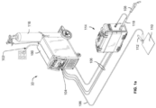
- FIG. 1a illustrates an exemplary welding-type system 10 including a welding power source 100.
- a source of power is provided to the welding power source 100 via an AC power cord 102.
- Typical ranges of AC power may be 115/230VAC or 208-575VAC, and may include single-phase or three-phase power.
- the welding power source 100 generally supplies power for the welding-type system 10.
- Weld output 104 provides welding output power via one or more weld cables 106 coupled to a modified welding torch 108 and a workpiece 110 using a clamp 112.
- Welding output power may be in the range of 10 Amps to 600 Amps or more, and range from 0 volts at short circuit to 44 volts or more into an open welding arc.
- Modern welding power sources and systems can provide welding-type power for various weld processes, which may include advanced waveform generation and control that is responsive to dynamic or static conditions at the welding arc.
- the illustrated welding-type system 10 includes a wire feeder 114 and a gas supply 116.
- the welding power source 100 may provide power and control to other equipment such as a wire feeder 114.
- the modified welding torch 108 is coupled to the wire feeder 114 via cable 118 in order to supply welding wire, shielding gas from the gas supply 116, and/or welding-type power to the welding torch 108 during operation of the welding-type system 10.
- the welding power source 100 may couple and/or directly supply welding-type power to the welding torch 108.
- the welding torch 108 is configured to preheat welding wire via polyphase electric arc preheating.
- the welding torch 108 contains three or more tungsten electrodes, which preheat the fed welding wire via arc wire heating.
- the three or more tungsten electrodes are connected to the welding power supply 100 to provide preheating power, and/or to a separate source of preheating power.
- the preheating power source (which may be the welding power supply 100) is configured to provide multi-phase power.
- the three electrodes are connected to three conductors which are connected to the three output phases of the preheating power source.
- the welding power source 100 may output welding-type power and also output three-phase heating power to the torch 108
- the three or more tungsten electrodes in the welding torch 108 may be connected to a dedicated polyphase preheating power source.
- the example welding-type system 10 of FIG. 1 has been described as a GMAW system, but the preheating system as disclosed can also be used, for example, to preheat Gas Tungsten Arc Welding ("GTAW") filler wire.
- GTAW Gas Tungsten Arc Welding
- the modified welding torch 108 may provide preheated welding filler wire for GTAW processes, flux-cored welding processes, metal-cored welding processes, submerged arc welding (SAW) processes, tandem welding processes, laser welding processes, hybrid welding processes, pulsed welding process, spray welding processes and/or any other processes involving adding wire filler metals.
- the preheating system may also be used to preheat wire electrode for deposition into a weld puddle in addition to conventional GMAW arc and electrode deposition, as a leading or trailing wire electrode deposition system.
- a die may be provided to curl preheated welding wire from the welding torch into a weld pool on the workpiece.
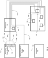
- FIG. 1b is a block diagram of the example welding system 10 of FIG 1a in which the system 10 includes a polyphase preheating power supply 130.
- the preheating power supply 130 is a three-phase power source which has three alternating current ("AC") outputs, output A 132, output B 134, and output C 136.
- Output A 132 is 120 degrees out of phase with output B 134 and output C 136
- output B 134 is 120 degrees of phase with output C 136.
- the three-phase power supply 130 is a regulated current power supply (e.g., the three-phase power supply 130 may be controlled to supply a consistent root mean square (“RMS”) current).
- RMS root mean square
- the AC outputs (132, 134, 136) operate at an RMS current between 1 and 100 Amps. In some examples, the RMS current may be less than 1 Amp. In some examples, the frequency of the AC outputs (132, 134, 136) is between 50 Hz and 20 kHz. High operating frequencies may be used to facilitate arc ignition and reignition and allows for lower operating currents.
- the preheating power supply 130 may be any power supply that is configured to provide a polyphase AC output at the desired frequency and current levels.
- Phase A 132 is connected via a conductor 138 to a first tungsten electrode 162 in the torch 108.
- Phase B 134 is connected via a conductor 140 to a second tungsten electrode 164 in the torch, and phase C 136 is connected via a conductor 142 to a third tungsten electrode 166 in the torch.
- the conductors 138, 140, and 142 connect to the torch 108 via the wire feeder 114.
- the conductors 138, 140, and 142 are included within the coupler 118, which also includes welding wire 152 fed by the wire feeder 114 from a welding wire source 150 as well as a power cable 106.
- Welding-type power provided by a welding-type power supply 100 is applied to the welding wire at the torch 108 via a contact tip 160.
- welding-type current arcs between the torch 108 and the workpiece 110, and the current returns from the workpiece 110 to the welding-type power supply 100 via a conductor 106.
- the contact tip 160 is closer to the torch tip 170 that the tungsten electrodes (162, 164, 166).
- the tungsten electrodes (162, 164, 166) are closer to the torch tip 170 that the contact tip 160.
- the three electrodes 162, 164, and 166 are physically arranged such that the electric arcs jump from an electrode (one of 162, 164, or 166) to the welding wire 152 and then to another electrode (one of 162, 164, or 166).
- the tungsten electrodes 162, 164, and 166 may be offset circumferentially by 120 degrees from each other and spaced along the length of the welding wire 152.
- a neutral line (not shown) is connected to the welding wire 152 (for example via the contact tip 160) and the preheating power supply 130 via a fourth conductor (not shown).
- a neutral conductor connects a fourth tungsten electrode to the preheating power supply 130.
- the preheating power supply 130 and the electrodes 162, 164, 166 may be configured in a delta configuration (e.g., without a neutral conductor) or in a Y configuration (e.g., using a neutral conductor).
- FIG. 2a shows an illustration of an isometric view of an example metal inert gas (“MIG") welding torch 200 configured to preheat welding wire.
- the welding torch 200 may implement the torch 108 of FIG. 1b .
- FIG. 2b shows a cross sectional view of the MIG welding torch 200.
- the handle of the MIG welding torch 200 is not shown in FIGs. 2a and 2b .
- the welding torch 200 includes a first tungsten electrode 202, a second tungsten electrode 204, and a third tungsten electrode 205 (which is not shown for ease of visibility).
- the first tungsten electrode 202 is connected to a first electric bus 206, and the second tungsten electrode 204 is connected to a second electric bus 208 (and the third tungsten electrode 205 is also connected to a third electric bus).
- the first electric bus 206 is connected to a power source (e.g., the power supply 130 of FIG. 1b ) via a first power cable 210, and the second electric bus is connected to a power source (e.g., the power supply 130 of FIG. 1b ) via a second power cable 212 (and the third electric bus is also connected to the power source).
- the welding torch 200 is supplied with shielding gas via shielding gas hose 214.
- the first tungsten electrode 202, the second tungsten electrode 204, and the third tungsten electrode 205 terminate in a chamber 216.
- the example chamber 216 is a ceramic tube, but may be another type of chamber configured to contain shielding gas adjacent the electrode wire traveling through the welding torch 200.
- the chamber 216 is supplied with shielding gas via the shielding gas hose 214.
- Welding wire is fed to the welding torch 200 via a wire liner 218.
- the wire liner 218 is connected to a connection block 220 via wire liner holder 222 and threaded wire liner holder 224.
- Fed welding wire enters a contact tip 226 from the wire liner 218, and then enters the chamber 216 via the contact tip 226.
- the contact tip 226 is connected to the connection block 220 via contact tip holder 228.
- the connection block 220 is connected to the preheating power source (e.g., the power supply 130 of FIG. 1b ) via a third power cable 230, which provides a neutral line for the preheating circuit.
- An insulator 232 insulates the connection block 220 from the first electric bus 206, the second electric bus 208, and the third electric bus.
- Preheated welding wire 238 exits the chamber 216 via a wire guide 234.
- Gas diffuser screens 236 diffuse shielding gas around the preheated welding wire 238 (e.g., the welding wire 152 of FIG. 1b ) that exits the chamber 216 via the wire guide 234.
- gas diffuser screen 236 diffuses shielding gas received from the chamber 216.
- gas diffuser screen is connected to a gas supply, for example gas supply 116 of FIG. 1a , via a dedicated shielding gas hose (not shown).
- the welding wire 152 is preheated inside the chamber 216 via electric arc preheating via arcs generated between the tungsten electrodes and the welding wire.
- Each tungsten electrode 202, 204 and 205 is connected to a separate phase of a polyphase (e.g., three-phase) preheating power source.
- preheating arcs may be between each tungsten electrode 202, 204, 205 and the welding wire.
- the welding wire is connected to a neutral line of the polyphase preheating power source.
- the contact tip 226 may be electrically coupled to a different terminal of the preheating power supply such that the tungsten electrode(s) 202, 204, 205, the arc(s), the welding wire, the contact tip 226, and the preheating power supply 130 form a preheating circuit (using appropriate electrical leads between the contact tip 226 and the preheating power supply 130 and between the tungsten electrode(s) 202, 204, 205 and the preheating power supply).
- FIG 3 illustrates an example preheating circuit, which may or may not include the contact tip 226.
- a separate neutral line is not used.
- the contact tip 226 may be connected to the preheating power source 130 as the neutral line and/or the electrodes 202, 204, 205 may be connected in a delta configuration without a neutral line.
- the distance between the tungsten electrodes (202, 204, and 205) and the welding wire is approximately 0.5 millimeters. In some examples, the positions of the tungsten electrodes 202, 204, and 205 are adjustable. In some examples, the arc gap is adjustable. In some examples, the distance between the tungsten electrodes 202, 204, and 205 and the welding wire is adjustable to accommodate different sizes of welding wire and/or to adjustments of the preheating arc voltage.
- Electrode positive polarity arc e.g., when the tungsten electrode (202, 204, or 205) has a positive voltage relative to the electrode wire
- Preheating aluminum welding wire with an electrode positive arc therefore removes the oxidation layer from the aluminum welding wire.
- the tungsten electrodes 202, 204 and 205 may be offset evenly circumferentially (e.g., each by 120 degrees from each other) in order to remove the oxide layer from all sides of the welding wire, as well as to evenly preheat the welding wire. In some examples, the tungsten electrodes 202, 204 and 205 may be evenly spaced around the circumference of the welding wire (e.g., each by 120 degrees from each other, plus or minus 30 degrees).
- the example chamber 216 is filled with shielding gas to prevent the re-oxidation of cleaned aluminum welding wire.
- the welding wire 238 may not be preheated inside of a chamber 216 (e.g., the preheating may be temporarily turned off or disabled).
- a nozzle may provide shielding gas to the preheated and cleaned aluminum welding wire to prevent the re-oxidation of the aluminum welding wire.
- the chamber 216 may include a nozzle portion (e.g., a taper at an end of the chamber 216 closest to the welding arc) to focus shielding gas flow toward the weld puddle.
- FIG. 3a is a block diagram of an exemplary electric arc preheating system 300, embodied, for example, in the welding torch 108 of FIG. 1b and 200 of FIGs. 2a and 2b .
- the preheating system 300 includes a first tungsten electrode 302 a second tungsten electrode 304, and a third tungsten electrode 306.
- the electrodes 302, 305, and 306 may implement the electrodes 162, 164, and 166 of FIG. 1b .
- the first tungsten electrode 302 is electrically connected to a first phase of the preheating power source 308, the second tungsten electrode 304 is electrically connected a second phase of the preheating power source 308, and the third tungsten electrode is electrically connected to a third phase of the preheating power source 308.
- the first, second, and third phases of the preheating power source 308 are 120 degrees out of phase with respect to each other.
- Welding wire 310 is fed through a contact tip 312 and delivered to a workpiece 314 via a wire guide 316.
- the contact tip 312 is electrically connected to a neutral line of the preheating power source 308.
- the contact tip is also electrically connected to a welding-type power source (not shown) in order to apply welding-type current to the welding wire 310.
- Welding wire 310 is preheated by electric arcs between the tungsten electrodes 302, 304, and 306 and the welding wire 310. At any given time, at least two arcs will exist between the electrodes 302, 304, and 306, and the wire 310.
- FIG. 3a shows the three arcs 322, 324, and 326, of which at least two will exist at any given time. The electric arcs 322, 324, and 326 jump from an electrode (302, 304, 306) to the welding wire 310 and then to another electrode (302, 304, 306).
- the two arcs (two of arcs 322, 324, and 326) that exist at any given time are in series, and therefore the total voltage drop across the arcs is equal to the sum of the voltage across each arc.
- using a three-phase system decreases the arc current by half while maintaining the same power level as compared to a preheating system which uses a single arc (e.g., between a single tungsten electrode and the wire 310).
- the tungsten electrodes 302, 304, and 306 are positioned between the contact tip 312 and the wire guide 316.
- the contact tip 312 may be closer to the wire guide 316 than the tungsten electrodes 302, 304, and 306.
- the electric arcs 322, 324, and 326 may occur inside of a chamber filled with shielding gas in order to prevent re-oxidation of the welding wire 310.
- FIG. 3b is an example scaled time plot 350 of the voltage at each electrode 302, 304, and 306 in a given cycle of the three phase power for.
- phase 1 is applied the first electrode 302
- phase 2 is applied to the second electrode 304
- phase 3 is applied to the third electrode 306.
- phase 1 connected to the first electrode 302 is commutating
- a first arc 326 exists from the third electrode 306 to the wire 310
- a second arc 324 exists from the wire 310 to the second electrode 304.
- Time T2 corresponds to the time when the phases of phase 1, phase 2, and phase 3, are 60 degrees in the periodic cycle.
- phase 3 connected to the third electrode 306 is commutating, a first arc 322 exists from the first electrode 302 to the wire 310, and a second arc 324 exists from the wire 310 to the second electrode 304.
- Time T3 corresponds to the time when the phases of phase 1, phase 2, and phase 3, are 120 degrees in the periodic cycle.
- phase 2 connected to the second electrode 304 is commutating, a first arc 322 exists from the first electrode 302 to the wire 310, and a second arc 326 exists from the wire 310 to the third electrode 306.
- Time T4 corresponds to the time when the phases of phase 1, phase 2, and phase 3, are 180 degrees in the periodic cycle.
- phase 1 connected to the first electrode 302 is commutating, a first arc 324 exists from the second electrode 304 to the wire 310, and a second arc 326 exists from the wire 310 to the third electrode 306.
- Time T5 corresponds to the time when the phases of phase 1, phase 2, and phase 3, are 240 degrees in the periodic cycle.
- phase 3 connected to the third electrode 306 is commutating, a first arc 324 exists from the second electrode 304 to the wire 310, and a second arc 322 exists from the wire 310 to the first electrode 302.
- Time T6 corresponds to the time when the phases of phase 1, phase 2, and phase 3, are 300 degrees in the periodic cycle.
- phase 2 connected to the second electrode 304 is commutating, a first arc 326 exists from the third electrode 306 to the wire 310, and a second arc 322 exists from the wire 310 to the first electrode 302.
- the power delivered to the wire 310 is the same (i.e., is uniform) across all time intervals.
- FIGs. 4a, 4b , 5a, and 5b illustrate views of example positioning of the preheating tungsten electrode(s) of the present disclosure.
- FIG. 4a shows a front view of a preheating system 400 using three preheating tungsten electrodes where each electrode is connected to a separate phase of a three-phase power supply.
- a first tungsten electrode 402, a second tungsten electrode 404, and a third tungsten electrode 406 are configured to preheat a welding wire 408.
- the first tungsten electrode 402, the second tungsten electrode 404, and the third tungsten electrode 406 are offset circumferentially (i.e. by 120 degrees) so as to evenly preheat the welding wire 408, as well as to evenly clean an aluminum welding wire 408.
- Preheating arcs occur between the three tungsten electrodes 402, 404, and 406, and the welding wire 408.
- An arc jumps from an electrode (402, 404, or 406) to the welding wire 408 and then to another electrode (402, 404, or 406).
- FIG. 4b shows that the tungsten electrodes 402, 404, and 406 are offset along the length of the welding wire 408.
- the tungsten electrodes 402, 404, and 406 are offset to ensure that the arcs jump from the electrodes (402, 404, or 406) to the welding wire 408 and then to another electrode (402, 404, or 406), rather than directly from electrode to electrode.
- FIG. 5a shows a front view of a preheating system 500 using four preheating tungsten electrodes where each electrode is connected to a separate phase of a four-phase power supply.
- a first tungsten electrode 502, a second tungsten electrode 504, a third tungsten electrode 506, and a fourth tungsten electrode 508 are configured to preheat a welding wire 510.
- the first tungsten electrode 502, the second tungsten electrode 504, the third tungsten electrode 506, and the fourth tungsten electrode 508 are offset circumferentially (i.e. by 90 degrees) so as to evenly preheat the welding wire 510, as well as to evenly clean an aluminum welding wire 510.
- Preheating arcs occur between the three tungsten electrodes 502, 504, 506, and 508, and the welding wire 510.
- An arc jumps from an electrode (502, 504, 506, or 508) to the welding wire 510 and then to another electrode (502, 504, 506, or 508).
- FIG. 5b shows that the tungsten electrodes 502, 504, 506, and 508 are offset along the length of the welding wire 510.
- the tungsten electrodes 502, 504, 506, and 508 are offset to ensure that the arcs jump from the electrodes (502, 504, 506, or 508) to the welding wire 510 and then to another electrode (502, 504, 506, or 508), rather than directly from electrode to electrode.
- Welding-type power supply and welding power source refers to any device capable of, when power is applied thereto, supplying welding, cladding, plasma cutting, induction heating, laser (including laser welding, laser hybrid, and laser cladding), carbon arc cutting or gouging and/or resistive preheating, including but not limited to transformer-rectifiers, inverters, converters, resonant power supplies, quasi-resonant power supplies, switch-mode power supplies, etc., as well as control circuitry and other ancillary circuitry associated therewith.
- Welding-type system includes any device capable of supplying power suitable for welding, plasma cutting, induction heating, CAC-A and/or hot wire welding/preheating (including laser welding and laser cladding), including inverters, converters, choppers, resonant power supplies, quasi-resonant power supplies, etc., as well as control circuitry and other ancillary circuitry associated therewith.
- Welding operation includes both actual welds (e.g., resulting in joining, such as welding or brazing) of two or more physical objects, an overlaying, texturing, and/or heat-treating of a physical object, and/or a cut of a physical object) and simulated or virtual welds (e.g., a visualization of a weld without a physical weld occurring).
- actual welds e.g., resulting in joining, such as welding or brazing
- simulated or virtual welds e.g., a visualization of a weld without a physical weld occurring.
- power is used throughout this specification for convenience, but also includes related measures such as energy, current, voltage, and enthalpy.
- controlling "power” may involve controlling voltage, current, energy, and/or enthalpy
- controlling based on “power” may involve controlling based on voltage, current, energy, and/or enthalpy.
- Electric power of the kind measured in watts as the product of voltage and current e.g., V*I power
- V*I power Electric power of the kind measured in watts as the product of voltage and current
- x and/or y means any element of the three-element set ⁇ (x), (y), (x, y) ⁇ . In other words, “x and/or y” means “one or both of x and y”.
- x, y, and/or z means any element of the seven-element set ⁇ (x), (y), (z), (x, y), (x, z), (y, z), (x, y, z) ⁇ . In other words, "x, y and/or z” means “one or more of x, y and z”.
- the term “exemplary” means serving as a non-limiting example, instance, or illustration.
- the terms “e.g.,” and “for example” set off lists of one or more non-limiting examples, instances, or illustrations.
Description
- The present disclosure relates to welding systems and, more particularly, to an apparatus for preheating welding wire, and to a system for preheating welding wire comprising the apparatus, see appended
claims - Welding is a process that has increasingly become ubiquitous in all industries. A wide range of welding systems and welding control regimes have been implemented for various purposes. In continuous welding operations, gas metal arc welding (GMAW) and submerged arc welding (SAW) techniques allow for formation of a continuing weld bead by feeding welding wire shielded by inert gas from a welding torch. Such wire feeding systems are available for other welding systems, such as tungsten inert gas (TIG) welding. Electrical power is applied to the welding wire and a circuit is completed through the workpiece to sustain a welding arc that melts the electrode wire and the workpiece to form the desired weld.
-
EP2666041 describes an example of a multi-stage fiber processing system which comprises first and second fiber holders configured to hold respective portions of at least one fiber and a plurality of heat sources arranged between the first and second fiber holders and configured to provide a heat zone that axially extends about the at least on fiber. -
US2018/354056 provides a starting point for the present invention and describes examples of systems, methods, and apparatus to preheat welding wire. An example welding torch includes: a welding assembly comprising: a first contact
tip configured to conduct welding current to a consumable electrode; and a second contact tip configured to conduct preheating current to the consumable electrode; a neck having a bend, the neck configured to hold the welding assembly and to deliver the consumable electrode to the welding assembly; a torch body configured to hold the neck opposite the welding assembly; and a torch mounting assembly; wherein the welding assembly, the neck, the bend, the torch body, and the torch mounting assembly are dimensioned such that the welding torch provides a same tool center point distance, a same bend angle, and a same approach angle when used to replace a second welding torch having a single contact tip. - According to the present invention, an apparatus for preheating welding wire, and a system for preheating welding wire comprising the apparatus are defined, respectively, in appended
claims -
-
FIG. 1a is an illustration of an example welding-type system in accordance with aspects of this disclosure. -
FIG. 1b is a block diagram of an example welding-type system in accordance with aspects of this disclosure. -
FIG. 2a is an illustration of an isometric view of a welding torch configured to preheat welding wire via electric arc preheating. -
FIG. 2b is an illustration of a cross-sectional view of the welding torch ofFIG. 2a , configured to preheat welding wire via electric arc preheating. -
FIG. 3a is a block diagram of an example electric arc preheating system illustrating a current path of the example electric arc preheating system. -
FIG. 3b is an example time plot of the voltages of the phases of three-phase power that may be applied to the electric arc preheating system ofFIG. 3a . -
FIG. 4a is an illustration of an example arrangement of an electric arc preheating system using three tungsten electrodes. -
FIG. 4b is a side view of the example electric arc preheating system ofFIG. 4a including three tungsten electrodes. -
FIG. 5a is an illustration of an example arrangement of an electric arc preheating system using four tungsten electrodes. -
FIG. 5b is a side view of the example electric arc preheating system ofFIG. 5a including four tungsten electrodes. - The figures are not necessarily to scale. Where appropriate, similar or identical reference numbers are used to refer to similar or identical components.
- An inch corresponds to 25.4 mm. In some welding applications, it is desirable to preheat the welding wire before the welding wire is deposited onto a workpiece. Preheating the welding wire can result in one or more advantages, such as reducing the heat to be applied to the workpiece via the welding arc, increasing deposition rates, and/or reducing hydrogen present in the weldment. For example, in systems in which welding wire is not preheated, the power from the welding arc must be sufficient to both
melt the base material and the ambient temperature welding wire. Systems in which welding wire is not preheated therefore may suffer from a low deposition rate and/or a low thermal efficiency. This low deposition rate and efficiency is due, in part, by the low energy transfer efficiency between the welding arc and the desired heated materials (i.e., a workpiece). - Additionally, in systems in which the welding wire is a filler material, excess energy is transferred to the workpiece, so that the weld pool has sufficient energy to melt the incoming filler. This excess energy is readily extracted from the desired location of heat application due to the high thermal diffusivity nature of metals. Addition of excess energy is undesirable, as the increased temperature can produce distortion, alter the metallurgical properties of the workpiece, increase atmospheric oxidation, and/or reduce efficiency of the welding electrical power.
- Conventional preheating methods use Joule, or resistive, preheating, inductive preheating, laser preheating, and/or infrared preheating. Direct Joule heating involves the conduction of current to a segment of the filler wire prior to the filler wire reaching the welding arc (or other application of the wire). Direct Joule heating can be performed by transferring current from work through the wire to a contact point and/or through a first contact point and through the wire to a second contact point. Direct Joule heating may involve using one or more additional cables to carry the preheating current, and the efficiency of direct Joule heating may depend on the electrical resistivity of the filler wire and the cable conductivity.
- A method to improve Joule heating involves decreasing the wire diameter and/or increasing wire feed speed to maintain the high deposition rates. Increasing wire feed speed is practical only to the point where processes can be stopped or corrected on a human timescale. If the wire has insufficient heat to melt at the weld puddle, a bird nest of hot wire can form around the welding torch. If the wire has excess heat, the wire can "burn back," in which case sparking and arcing is created, and material is not deposited where desired and/or the welding torch may be damaged.
- Electric arc wire heating is the application of an electrical arc to the welding wire. For example, one or more nonconsumable electrodes (e.g., tungsten or tungsten-alloy electrodes) may be used to create an arc between the nonconsumable electrode and the welding wire. The power delivered via the arc preheats the welding wire to a desired temperature. An advantage of electric arc wire heating over Joule heating is the current requirement reduction. The arc voltage drop appreciably decreases both the current requirement and the subsequent cable/connection losses attributed with high current applications. Since the heat generation is primarily from the arc, the electrical conductivity of the filler wire does not have a significant role in overall system efficiency. Electric arc wire heating therefore maintains similar performance for all metals and alloys. The arc is stable at small arc lengths and slow wire feed speeds. The present disclosure relates to apparatus, systems, and methods of using electrical arc(s) to preheat welding wire.
- Additionally, the disclosed preheating system achieves a greater deposition rate as compared to cold wire welding, or conventional preheating systems. For example, TIG welding using the disclosed electric arc preheating system can achieve deposition rates of 200 inches per minute using 0.063" diameter wire. Currently, cold wire TIG welding achieves a deposition rate of 12 inches per minute using a 0.063" diameter wire.
- An advantage of the present disclosure is that electrical arc(s) can be used to remove the oxide layer of aluminum welding wire. Aluminum is highly reactive, and forms a surface oxide layer when exposed to atmospheric conditions. The oxide layer contains significant amounts of water from atmospheric humidity. The water provides a source of hydrogen, which can cause porosity in an aluminum weld. Therefore, it is advantageous to remove the oxide layer, and to reduce or prevent the re-formation of the oxide layer after cleaning. Accordingly, disclosed systems and methods may be configured to remove the oxide layer of aluminum welding (as well as any other surface contaminant) via electric arc preheating of the wire. Shielding gas is provided to prevent the re-formation of the oxide layer on the aluminum welding wire.
- Additionally, disclosed example systems and methods remove organic contaminants (e.g., hydrocarbons) from welding wire during the preheating process. Removing organic contaminants prevents weld defects caused by "dirty" welding wire, which can include porosity in the weld.
- Additionally, disclosed preheating systems and methods can be retrofit into existing welding guns/torches. Existing welding torches may be modified to include one or more tungsten electrodes configured to preheat welding wire via arc preheating.
- Preheating systems that use multiple electrodes connected to a polyphase power source (e.g., three electrodes are connected to the three phases of a three-phase power source), provide additional advantages. For example, in disclosed example three-phase preheating systems, when three-phase power is applied to the preheating electrodes, at least two electric arcs will exist at all times to preheat the welding wire. The existing electric arcs also facilitate reignition of commutating arcs. Further, since polyphase systems utilize alternating current, when polyphase systems are utilized, at any given time at least one arc is electrode positive, which facilitates removal of contaminants from aluminum welding wire.
-
FIG. 1a illustrates an exemplary welding-type system 10 including awelding power source 100. A source of power is provided to thewelding power source 100 via anAC power cord 102. Typical ranges of AC power may be 115/230VAC or 208-575VAC, and may include single-phase or three-phase power. Thewelding power source 100 generally supplies power for the welding-type system 10.Weld output 104 provides welding output power via one ormore weld cables 106 coupled to a modifiedwelding torch 108 and aworkpiece 110 using aclamp 112. Welding output power may be in the range of 10 Amps to 600 Amps or more, and range from 0 volts at short circuit to 44 volts or more into an open welding arc. Modern welding power sources and systems can provide welding-type power for various weld processes, which may include advanced waveform generation and control that is responsive to dynamic or static conditions at the welding arc. - The illustrated welding-
type system 10 includes awire feeder 114 and agas supply 116. Thewelding power source 100 may provide power and control to other equipment such as awire feeder 114. In the illustrated example, the modifiedwelding torch 108 is coupled to thewire feeder 114 viacable 118 in order to supply welding wire, shielding gas from thegas supply 116, and/or welding-type power to thewelding torch 108 during operation of the welding-type system 10. In some examples, thewelding power source 100 may couple and/or directly supply welding-type power to thewelding torch 108. - As described in more detail below, the
welding torch 108 is configured to preheat welding wire via polyphase electric arc preheating. Thewelding torch 108 contains three or more tungsten electrodes, which preheat the fed welding wire via arc wire heating. In the welding-type system 100, the three or more tungsten electrodes are connected to thewelding power supply 100 to provide preheating power, and/or to a separate source of preheating power. Accordingly, the preheating power source (which may be the welding power supply 100) is configured to provide multi-phase power. For example, in a three-phase system, the three electrodes are connected to three conductors which are connected to the three output phases of the preheating power source. In some examples, thewelding power source 100 may output welding-type power and also output three-phase heating power to thetorch 108 As explained in more detail below, in some examples, the three or more tungsten electrodes in thewelding torch 108 may be connected to a dedicated polyphase preheating power source. - The example welding-
type system 10 ofFIG. 1 has been described as a GMAW system, but the preheating system as disclosed can also be used, for example, to preheat Gas Tungsten Arc Welding ("GTAW") filler wire. For example, the modifiedwelding torch 108 may provide preheated welding filler wire for GTAW processes, flux-cored welding processes, metal-cored welding processes, submerged arc welding (SAW) processes, tandem welding processes, laser welding processes, hybrid welding processes, pulsed welding process, spray welding processes and/or any other processes involving adding wire filler metals. The preheating system may also be used to preheat wire electrode for deposition into a weld puddle in addition to conventional GMAW arc and electrode deposition, as a leading or trailing wire electrode deposition system. In some examples, a die may be provided to curl preheated welding wire from the welding torch into a weld pool on the workpiece. -
FIG. 1b is a block diagram of theexample welding system 10 ofFIG 1a in which thesystem 10 includes a polyphasepreheating power supply 130. As illustrated, the preheatingpower supply 130 is a three-phase power source which has three alternating current ("AC") outputs,output A 132,output B 134, andoutput C 136.Output A 132 is 120 degrees out of phase withoutput B 134 andoutput C 136, andoutput B 134 is 120 degrees of phase withoutput C 136. In some examples, the three-phase power supply 130 is a regulated current power supply (e.g., the three-phase power supply 130 may be controlled to supply a consistent root mean square ("RMS") current). In some examples, the AC outputs (132, 134, 136) operate at an RMS current between 1 and 100 Amps. In some examples, the RMS current may be less than 1 Amp. In some examples, the frequency of the AC outputs (132, 134, 136) is between 50 Hz and 20 kHz. High operating frequencies may be used to facilitate arc ignition and reignition and allows for lower operating currents. The preheatingpower supply 130 may be any power supply that is configured to provide a polyphase AC output at the desired frequency and current levels. -
Phase A 132 is connected via aconductor 138 to afirst tungsten electrode 162 in thetorch 108.Phase B 134 is connected via aconductor 140 to asecond tungsten electrode 164 in the torch, andphase C 136 is connected via aconductor 142 to athird tungsten electrode 166 in the torch. Theconductors torch 108 via thewire feeder 114. In some examples, between thewire feeder 114 and thetorch 108, theconductors coupler 118, which also includeswelding wire 152 fed by thewire feeder 114 from awelding wire source 150 as well as apower cable 106. Welding-type power provided by a welding-type power supply 100 is applied to the welding wire at thetorch 108 via acontact tip 160. During a welding operation, welding-type current arcs between thetorch 108 and theworkpiece 110, and the current returns from theworkpiece 110 to the welding-type power supply 100 via aconductor 106. In some examples, thecontact tip 160 is closer to thetorch tip 170 that the tungsten electrodes (162, 164, 166). In some examples, the tungsten electrodes (162, 164, 166) are closer to thetorch tip 170 that thecontact tip 160. - The three
conductors tungsten electrodes tungsten electrodes electrodes welding wire 152 and then to another electrode (one of 162, 164, or 166). For example, thetungsten electrodes welding wire 152. In some examples a neutral line (not shown) is connected to the welding wire 152 (for example via the contact tip 160) and the preheatingpower supply 130 via a fourth conductor (not shown). In some examples, a neutral conductor connects a fourth tungsten electrode to the preheatingpower supply 130. The preheatingpower supply 130 and theelectrodes -
FIG. 2a shows an illustration of an isometric view of an example metal inert gas ("MIG")welding torch 200 configured to preheat welding wire. Thewelding torch 200 may implement thetorch 108 ofFIG. 1b .FIG. 2b shows a cross sectional view of theMIG welding torch 200. The handle of theMIG welding torch 200 is not shown inFIGs. 2a and2b . Thewelding torch 200 includes afirst tungsten electrode 202, asecond tungsten electrode 204, and a third tungsten electrode 205 (which is not shown for ease of visibility). Thefirst tungsten electrode 202 is connected to a firstelectric bus 206, and thesecond tungsten electrode 204 is connected to a second electric bus 208 (and the third tungsten electrode 205 is also connected to a third electric bus). The firstelectric bus 206 is connected to a power source (e.g., thepower supply 130 ofFIG. 1b ) via afirst power cable 210, and the second electric bus is connected to a power source (e.g., thepower supply 130 ofFIG. 1b ) via a second power cable 212 (and the third electric bus is also connected to the power source). Thewelding torch 200 is supplied with shielding gas via shieldinggas hose 214. - The
first tungsten electrode 202, thesecond tungsten electrode 204, and the third tungsten electrode 205 (which may implement theelectrodes chamber 216. Theexample chamber 216 is a ceramic tube, but may be another type of chamber configured to contain shielding gas adjacent the electrode wire traveling through thewelding torch 200. Thechamber 216 is supplied with shielding gas via the shieldinggas hose 214. Welding wire is fed to thewelding torch 200 via awire liner 218. Thewire liner 218 is connected to aconnection block 220 viawire liner holder 222 and threadedwire liner holder 224. Fed welding wire enters acontact tip 226 from thewire liner 218, and then enters thechamber 216 via thecontact tip 226. Thecontact tip 226 is connected to theconnection block 220 viacontact tip holder 228. Theconnection block 220 is connected to the preheating power source (e.g., thepower supply 130 ofFIG. 1b ) via athird power cable 230, which provides a neutral line for the preheating circuit. - An
insulator 232 insulates the connection block 220 from the firstelectric bus 206, the secondelectric bus 208, and the third electric bus.Preheated welding wire 238 exits thechamber 216 via awire guide 234. Gas diffuser screens 236 diffuse shielding gas around the preheated welding wire 238 (e.g., thewelding wire 152 ofFIG. 1b ) that exits thechamber 216 via thewire guide 234. In some examples,gas diffuser screen 236 diffuses shielding gas received from thechamber 216. In some examples, gas diffuser screen is connected to a gas supply, forexample gas supply 116 ofFIG. 1a , via a dedicated shielding gas hose (not shown). Thewelding wire 152 is preheated inside thechamber 216 via electric arc preheating via arcs generated between the tungsten electrodes and the welding wire. Eachtungsten electrode - As described in more detail below, in some examples preheating arcs may be between each
tungsten electrode contact tip 226 may be electrically coupled to a different terminal of the preheating power supply such that the tungsten electrode(s) 202, 204, 205, the arc(s), the welding wire, thecontact tip 226, and the preheatingpower supply 130 form a preheating circuit (using appropriate electrical leads between thecontact tip 226 and the preheatingpower supply 130 and between the tungsten electrode(s) 202, 204, 205 and the preheating power supply).FIG. 3 illustrates an example preheating circuit, which may or may not include thecontact tip 226. In some examples, a separate neutral line is not used. Thecontact tip 226 may be connected to the preheatingpower source 130 as the neutral line and/or theelectrodes - The distance between the tungsten electrodes (202, 204, and 205) and the welding wire is approximately 0.5 millimeters. In some examples, the positions of the
tungsten electrodes tungsten electrodes - Because the tungsten electrodes are connected to an AC polyphase power supply (e.g., a three-phase power supply), during operation, at least one arc is electrode positive at all times. Electrode positive polarity arc (e.g., when the tungsten electrode (202, 204, or 205) has a positive voltage relative to the electrode wire) more readily remove oxidation layers on aluminum welding wire compared to electrode negative polarity. Preheating aluminum welding wire with an electrode positive arc therefore removes the oxidation layer from the aluminum welding wire. The
tungsten electrodes tungsten electrodes - The
example chamber 216 is filled with shielding gas to prevent the re-oxidation of cleaned aluminum welding wire. In some examples, thewelding wire 238 may not be preheated inside of a chamber 216 (e.g., the preheating may be temporarily turned off or disabled). In some such examples, a nozzle may provide shielding gas to the preheated and cleaned aluminum welding wire to prevent the re-oxidation of the aluminum welding wire. Additionally or alternatively, thechamber 216 may include a nozzle portion (e.g., a taper at an end of thechamber 216 closest to the welding arc) to focus shielding gas flow toward the weld puddle. -
FIG. 3a is a block diagram of an exemplary electricarc preheating system 300, embodied, for example, in thewelding torch 108 ofFIG. 1b and 200 ofFIGs. 2a and2b . The preheatingsystem 300 includes a first tungsten electrode 302 asecond tungsten electrode 304, and athird tungsten electrode 306. Theelectrodes electrodes FIG. 1b . Thefirst tungsten electrode 302 is electrically connected to a first phase of the preheating power source 308, thesecond tungsten electrode 304 is electrically connected a second phase of the preheating power source 308, and the third tungsten electrode is electrically connected to a third phase of the preheating power source 308. The first, second, and third phases of the preheating power source 308 are 120 degrees out of phase with respect to each other. -
Welding wire 310 is fed through acontact tip 312 and delivered to aworkpiece 314 via awire guide 316. Thecontact tip 312 is electrically connected to a neutral line of the preheating power source 308. The contact tip is also electrically connected to a welding-type power source (not shown) in order to apply welding-type current to thewelding wire 310. -
Welding wire 310 is preheated by electric arcs between thetungsten electrodes welding wire 310. At any given time, at least two arcs will exist between theelectrodes wire 310.FIG. 3a shows the threearcs welding wire 310 and then to another electrode (302, 304, 306). The two arcs (two ofarcs - As illustrated, the
tungsten electrodes contact tip 312 and thewire guide 316. In some examples, thecontact tip 312 may be closer to thewire guide 316 than thetungsten electrodes FIGS. 2a and2b , the electric arcs 322, 324, and 326 may occur inside of a chamber filled with shielding gas in order to prevent re-oxidation of thewelding wire 310. -
FIG. 3b is an example scaledtime plot 350 of the voltage at eachelectrode phase 1 is applied thefirst electrode 302,phase 2 is applied to thesecond electrode 304, and phase 3 is applied to thethird electrode 306. At time T1,phase 1 connected to thefirst electrode 302 is commutating, afirst arc 326 exists from thethird electrode 306 to thewire 310, and asecond arc 324 exists from thewire 310 to thesecond electrode 304. - Time T2 corresponds to the time when the phases of
phase 1,phase 2, and phase 3, are 60 degrees in the periodic cycle. At time T2, phase 3 connected to thethird electrode 306 is commutating, afirst arc 322 exists from thefirst electrode 302 to thewire 310, and asecond arc 324 exists from thewire 310 to thesecond electrode 304. - Time T3 corresponds to the time when the phases of
phase 1,phase 2, and phase 3, are 120 degrees in the periodic cycle. At time T2,phase 2 connected to thesecond electrode 304 is commutating, afirst arc 322 exists from thefirst electrode 302 to thewire 310, and asecond arc 326 exists from thewire 310 to thethird electrode 306. - Time T4 corresponds to the time when the phases of
phase 1,phase 2, and phase 3, are 180 degrees in the periodic cycle. At time T4,phase 1 connected to thefirst electrode 302 is commutating, afirst arc 324 exists from thesecond electrode 304 to thewire 310, and asecond arc 326 exists from thewire 310 to thethird electrode 306. - Time T5 corresponds to the time when the phases of
phase 1,phase 2, and phase 3, are 240 degrees in the periodic cycle. At time T5, phase 3 connected to thethird electrode 306 is commutating, afirst arc 324 exists from thesecond electrode 304 to thewire 310, and asecond arc 322 exists from thewire 310 to thefirst electrode 302. - Time T6 corresponds to the time when the phases of
phase 1,phase 2, and phase 3, are 300 degrees in the periodic cycle. At time T6,phase 2 connected to thesecond electrode 304 is commutating, afirst arc 326 exists from thethird electrode 306 to thewire 310, and asecond arc 322 exists from thewire 310 to thefirst electrode 302. - As will be understood with reference to
FIG. 3b , in thesystem 300, when three-phase power is applied to theelectrodes wire 310 is the same (i.e., is uniform) across all time intervals. -
FIGs. 4a, 4b ,5a, and 5b illustrate views of example positioning of the preheating tungsten electrode(s) of the present disclosure. -
FIG. 4a shows a front view of apreheating system 400 using three preheating tungsten electrodes where each electrode is connected to a separate phase of a three-phase power supply. Afirst tungsten electrode 402, asecond tungsten electrode 404, and athird tungsten electrode 406 are configured to preheat awelding wire 408. Thefirst tungsten electrode 402, thesecond tungsten electrode 404, and thethird tungsten electrode 406 are offset circumferentially (i.e. by 120 degrees) so as to evenly preheat thewelding wire 408, as well as to evenly clean analuminum welding wire 408. Preheating arcs occur between the threetungsten electrodes welding wire 408. An arc jumps from an electrode (402, 404, or 406) to thewelding wire 408 and then to another electrode (402, 404, or 406). -
FIG. 4b shows that thetungsten electrodes welding wire 408. Thetungsten electrodes welding wire 408 and then to another electrode (402, 404, or 406), rather than directly from electrode to electrode. -
FIG. 5a shows a front view of apreheating system 500 using four preheating tungsten electrodes where each electrode is connected to a separate phase of a four-phase power supply. Afirst tungsten electrode 502, asecond tungsten electrode 504, athird tungsten electrode 506, and afourth tungsten electrode 508 are configured to preheat awelding wire 510. Thefirst tungsten electrode 502, thesecond tungsten electrode 504, thethird tungsten electrode 506, and thefourth tungsten electrode 508 are offset circumferentially (i.e. by 90 degrees) so as to evenly preheat thewelding wire 510, as well as to evenly clean analuminum welding wire 510. Preheating arcs occur between the threetungsten electrodes welding wire 510. An arc jumps from an electrode (502, 504, 506, or 508) to thewelding wire 510 and then to another electrode (502, 504, 506, or 508). -
FIG. 5b shows that thetungsten electrodes welding wire 510. Thetungsten electrodes welding wire 510 and then to another electrode (502, 504, 506, or 508), rather than directly from electrode to electrode. - Welding-type power supply and welding power source, as used herein, refers to any device capable of, when power is applied thereto, supplying welding, cladding, plasma cutting, induction heating, laser (including laser welding, laser hybrid, and laser cladding), carbon arc cutting or gouging and/or resistive preheating, including but not limited to transformer-rectifiers, inverters, converters, resonant power supplies, quasi-resonant power supplies, switch-mode power supplies, etc., as well as control circuitry and other ancillary circuitry associated therewith.
- Welding-type system, as used herein, includes any device capable of supplying power suitable for welding, plasma cutting, induction heating, CAC-A and/or hot wire welding/preheating (including laser welding and laser cladding), including inverters, converters, choppers, resonant power supplies, quasi-resonant power supplies, etc., as well as control circuitry and other ancillary circuitry associated therewith.
- Welding operation, as used herein, includes both actual welds (e.g., resulting in joining, such as welding or brazing) of two or more physical objects, an overlaying, texturing, and/or heat-treating of a physical object, and/or a cut of a physical object) and simulated or virtual welds (e.g., a visualization of a weld without a physical weld occurring).
- The term "power" is used throughout this specification for convenience, but also includes related measures such as energy, current, voltage, and enthalpy. For example, controlling "power" may involve controlling voltage, current, energy, and/or enthalpy, and/or controlling based on "power" may involve controlling based on voltage, current, energy, and/or enthalpy. Electric power of the kind measured in watts as the product of voltage and current (e.g., V*I power) is referred to herein as "wattage."
- As utilized herein, "and/or" means any one or more of the items in the list joined by "and/or". As an example, "x and/or y" means any element of the three-element set {(x), (y), (x, y)}. In other words, "x and/or y" means "one or both of x and y". As another example, "x, y, and/or z" means any element of the seven-element set {(x), (y), (z), (x, y), (x, z), (y, z), (x, y, z)}. In other words, "x, y and/or z" means "one or more of x, y and z". As utilized herein, the term "exemplary" means serving as a non-limiting example, instance, or illustration. As utilized herein, the terms "e.g.," and "for example" set off lists of one or more non-limiting examples, instances, or illustrations.
- While the present method and/or system has been described with reference to certain implementations, it will be understood by those skilled in the art that various changes may be made and equivalents may be substituted without departing from the scope of the present invention as defined in the appended claims.
Claims (11)
- An apparatus for preheating welding wire (152), the apparatus comprising:an input configured to receive multi-phase power;a first tungsten electrode (162, 202) connected via a first conductor (138, 206) to the input, wherein the first conductor (138, 206) is configured to conduct a first phase (132) of the multi-phase power received at the input;a second tungsten electrode (164, 204) connected via a second conductor (140, 208) to the input, wherein the second conductor (140, 208) is configured to conduct a second phase (134) of the multi-phase power received at the input;a third tungsten electrode (166, 205) connected via a third conductor (142) to the input, wherein the third conductor (142) is configured to conduct a third phase (136) of the multi-phase power received at the input;a first region (216);a contact tip (160, 226, 312) configured to deliver the welding wire (152) to the first region (216) for preheating;a wire guide (234) configured to deliver preheated welding wire (238) from the first region (216) to a workpiece; anda gas connecter configured to deliver shielding gas to the first region (216) around the preheated welding wire (238) delivered to the workpiece;wherein the first, second and third electrodes are configured to preheat welding wire (152) via electric arc preheating and wherein the electric arc preheating occurs within the first region (216).
- The apparatus of claim 1, wherein the multi-phase power is three-phase power.
- The apparatus of claim 2, wherein the first tungsten electrode (162, 202) is offset from the second tungsten electrode (164, 204) around a circumference of the welding wire (152) being preheated by 120 degrees, and the third tungsten electrode (166, 205) is offset circumferentially from the second tungsten electrode (164, 204) around a circumference of the welding wire (152) by 120 degrees, and wherein welding wire (152) is fed generally between the first tungsten electrode (162, 202), the second tungsten electrode (164, 204), and the third tungsten electrode (166, 205), and
optionally wherein the first tungsten electrode (162, 202) is offset along a length of the welding wire (152) from the second tungsten electrode (164, 204), the first tungsten electrode (162, 202) is offset along a length of the wire (152) from the third tungsten electrode (166, 205), and the second tungsten electrode (164, 204) is offset along a length of the wire (152) from the third tungsten electrode (166, 205). - The apparatus of claim 2, wherein, in use, during a period when three-phase power is applied to the input, at least two electric arcs exist between a welding wire (152) and at least two of the first tungsten electrode (162, 202), the second tungsten electrode (164, 204), or the third tungsten electrode (166, 205).
- The apparatus of claim 1, wherein the first tungsten electrode (202), the second tungsten electrode (204), and the third tungsten electrode (205) are approximately evenly spaced around a circumference of the welding wire (152) being preheated.
- The apparatus of claim 1, further comprising a neutral conductor electrically connectable to the welding wire (152) and configured to connect via the input to a neutral line of the multi-phase power.
- The apparatus of claim 1, wherein the apparatus is a gas metal arc welding (GMAW) torch, and optionally wherein the contact tip (160, 226) is electrically connected to the welding wire (152) and a welding power source (100).
- The apparatus of claim 1, wherein the multi-phase power is configured to provide a regulated current.
- The apparatus of claim 1, wherein the multi-phase power is configured to operate between and 50 and 20000 hertz.
- A system for preheating welding wire, the system comprising:a multi-phase power source; andcharacterized in that the system comprises an apparatus according to claim 1.
- The system of claim 10, wherein the multi-phase power is three-phase power, and
optionally wherein the first tungsten electrode (162, 202) is offset from the second tungsten electrode (165, 204) around a circumference of the welding wire (152) being preheated by 120 degrees, and the third tungsten electrode (166, 205) is offset circumferentially from the second tungsten electrode (165, 204) around a circumference of the welding wire (152) by 120 degrees, and wherein welding wire (152) is fed generally between the first tungsten electrode (162, 202), the second tungsten electrode (165, 204), and the third tungsten electrode (166, 205).
Applications Claiming Priority (2)
| Application Number | Priority Date | Filing Date | Title |
|---|---|---|---|
| US201962892116P | 2019-08-27 | 2019-08-27 | |
| US16/936,070 US11745283B2 (en) | 2019-08-27 | 2020-07-22 | Methods for wire surface oxidation removal and/or wire preheating using polyphase electric arc preheating |
Publications (2)
| Publication Number | Publication Date |
|---|---|
| EP3799987A1 EP3799987A1 (en) | 2021-04-07 |
| EP3799987B1 true EP3799987B1 (en) | 2024-02-21 |
Family
ID=74681506
Family Applications (1)
| Application Number | Title | Priority Date | Filing Date |
|---|---|---|---|
| EP20192102.0A Active EP3799987B1 (en) | 2019-08-27 | 2020-08-21 | Apparatus and system for wire preheating using polyphase electric arc preheating |
Country Status (3)
| Country | Link |
|---|---|
| US (1) | US11745283B2 (en) |
| EP (1) | EP3799987B1 (en) |
| CN (1) | CN112439983A (en) |
Citations (1)
| Publication number | Priority date | Publication date | Assignee | Title |
|---|---|---|---|---|
| EP2666041B1 (en) * | 2011-01-19 | 2015-06-17 | 3SAE Technologies, Inc. | Multi-stage fiber processing system and method |
Family Cites Families (12)
| Publication number | Priority date | Publication date | Assignee | Title |
|---|---|---|---|---|
| JPS62207583A (en) | 1986-03-10 | 1987-09-11 | Chiyoda Chem Eng & Constr Co Ltd | Hot wire tig welding method |
| CN100335223C (en) | 2005-04-26 | 2007-09-05 | 哈尔滨工业大学 | Argon arc preheating wire welding method |
| US9028158B2 (en) * | 2007-02-07 | 2015-05-12 | 3Sae Technologies, Inc. | Multi-stage fiber processing system and method |
| CN102000903B (en) | 2010-10-27 | 2012-07-11 | 哈尔滨工业大学 | TIG (tungsten inert gas welding) power assistant double TIG (tungsten inert gas welding) compound heat source welding equipment and method |
| CN102528243A (en) | 2011-12-15 | 2012-07-04 | 哈尔滨工业大学 | Arc welding-brazing method for titanium-aluminum dissimilar alloy TIG (tungsten inert gas) arc preheating |
| US20140008354A1 (en) | 2012-07-06 | 2014-01-09 | Lincoln Global, Inc. | Method and system of using induction heating to heat consumable during hot wire process |
| US9937580B2 (en) | 2014-01-24 | 2018-04-10 | Lincoln Global, Inc. | Method and system for additive manufacturing using high energy source and hot-wire |
| US10675699B2 (en) | 2015-12-10 | 2020-06-09 | Illinois Tool Works Inc. | Systems, methods, and apparatus to preheat welding wire |
| US20180099346A1 (en) | 2015-12-10 | 2018-04-12 | Illinois Tool Works Inc. | Systems, methods, and apparatus to preheat welding wire |
| US11000913B2 (en) | 2016-02-23 | 2021-05-11 | Fronius International Gmbh | Welding device with a laser preheater for filler wire |
| CN111372711A (en) | 2017-06-09 | 2020-07-03 | 伊利诺斯工具制品有限公司 | Welding torch with first and second contact tips for preheating a welding wire |
| CN108581156A (en) * | 2018-06-19 | 2018-09-28 | 哈尔滨工程大学 | Double tungsten electrode plasma arc welding (PAW) connection devices based on center heated filament and welding method |
-
2020
- 2020-07-22 US US16/936,070 patent/US11745283B2/en active Active
- 2020-08-21 EP EP20192102.0A patent/EP3799987B1/en active Active
- 2020-08-26 CN CN202010871102.6A patent/CN112439983A/en active Pending
Patent Citations (1)
| Publication number | Priority date | Publication date | Assignee | Title |
|---|---|---|---|---|
| EP2666041B1 (en) * | 2011-01-19 | 2015-06-17 | 3SAE Technologies, Inc. | Multi-stage fiber processing system and method |
Also Published As
| Publication number | Publication date |
|---|---|
| US11745283B2 (en) | 2023-09-05 |
| CN112439983A (en) | 2021-03-05 |
| US20210060684A1 (en) | 2021-03-04 |
| EP3799987A1 (en) | 2021-04-07 |
Similar Documents
| Publication | Publication Date | Title |
|---|---|---|
| CN110621434B (en) | System and method for preheating welding wire | |
| US3549857A (en) | Welding processes and apparatus | |
| EP2379271B1 (en) | Double wire gmaw welding torch assembly and process | |
| US3122629A (en) | Consumable electrode arcless electric working | |
| US11911859B2 (en) | Systems, methods, and apparatus to provide preheat voltage feedback loss protection | |
| EP4257277A2 (en) | Systems, methods, and apparatus to control welding electrode preheating | |
| US11446756B2 (en) | Systems and methods for wire surface oxidation removal and/or wire preheating using a tungsten arc | |
| EP3799987B1 (en) | Apparatus and system for wire preheating using polyphase electric arc preheating | |
| WO2015124977A1 (en) | Hybrid hot-wire and arc welding method and system using offset positioning | |
| EP3838468A1 (en) | Methods and systems for gas control during welding wire pretreatments | |
| US11897062B2 (en) | Systems, methods, and apparatus to preheat welding wire | |
| US11772182B2 (en) | Systems and methods for gas control during welding wire pretreatments | |
| CA3078063C (en) | Methods and apparatus to provide welding-type power and preheating power | |
| US11845150B2 (en) | Methods and apparatus to provide welding-type power and preheating power | |
| JP3948767B2 (en) | High frequency AC TIG welding machine | |
| DePauw | Arc Welding of Aluminum Alloys | |
| JPS5812108B2 (en) | Method of welding in thermally ionized gas and welding torch | |
| JPS63101082A (en) | Welding machine with both tig-mig characteristics |
Legal Events
| Date | Code | Title | Description |
|---|---|---|---|
| PUAI | Public reference made under article 153(3) epc to a published international application that has entered the european phase |
Free format text: ORIGINAL CODE: 0009012 |
|
| STAA | Information on the status of an ep patent application or granted ep patent |
Free format text: STATUS: THE APPLICATION HAS BEEN PUBLISHED |
|
| AK | Designated contracting states |
Kind code of ref document: A1 Designated state(s): AL AT BE BG CH CY CZ DE DK EE ES FI FR GB GR HR HU IE IS IT LI LT LU LV MC MK MT NL NO PL PT RO RS SE SI SK SM TR |
|
| AX | Request for extension of the european patent |
Extension state: BA ME |
|
| STAA | Information on the status of an ep patent application or granted ep patent |
Free format text: STATUS: REQUEST FOR EXAMINATION WAS MADE |
|
| 17P | Request for examination filed |
Effective date: 20210920 |
|
| RBV | Designated contracting states (corrected) |
Designated state(s): AL AT BE BG CH CY CZ DE DK EE ES FI FR GB GR HR HU IE IS IT LI LT LU LV MC MK MT NL NO PL PT RO RS SE SI SK SM TR |
|
| STAA | Information on the status of an ep patent application or granted ep patent |
Free format text: STATUS: EXAMINATION IS IN PROGRESS |
|
| 17Q | First examination report despatched |
Effective date: 20220211 |
|
| GRAP | Despatch of communication of intention to grant a patent |
Free format text: ORIGINAL CODE: EPIDOSNIGR1 |
|
| STAA | Information on the status of an ep patent application or granted ep patent |
Free format text: STATUS: GRANT OF PATENT IS INTENDED |
|
| INTG | Intention to grant announced |
Effective date: 20230818 |
|
| RIN1 | Information on inventor provided before grant (corrected) |
Inventor name: HOEGER, MICHAEL V. |
|
| GRAJ | Information related to disapproval of communication of intention to grant by the applicant or resumption of examination proceedings by the epo deleted |
Free format text: ORIGINAL CODE: EPIDOSDIGR1 |
|
| STAA | Information on the status of an ep patent application or granted ep patent |
Free format text: STATUS: EXAMINATION IS IN PROGRESS |
|
| GRAP | Despatch of communication of intention to grant a patent |
Free format text: ORIGINAL CODE: EPIDOSNIGR1 |
|
| STAA | Information on the status of an ep patent application or granted ep patent |
Free format text: STATUS: GRANT OF PATENT IS INTENDED |
|
| INTC | Intention to grant announced (deleted) | ||
| INTG | Intention to grant announced |
Effective date: 20231018 |
|
| P01 | Opt-out of the competence of the unified patent court (upc) registered |
Effective date: 20231124 |
|
| GRAS | Grant fee paid |
Free format text: ORIGINAL CODE: EPIDOSNIGR3 |
|
| GRAA | (expected) grant |
Free format text: ORIGINAL CODE: 0009210 |
|
| STAA | Information on the status of an ep patent application or granted ep patent |
Free format text: STATUS: THE PATENT HAS BEEN GRANTED |
|
| AK | Designated contracting states |
Kind code of ref document: B1 Designated state(s): AL AT BE BG CH CY CZ DE DK EE ES FI FR GB GR HR HU IE IS IT LI LT LU LV MC MK MT NL NO PL PT RO RS SE SI SK SM TR |
|
| REG | Reference to a national code |
Ref country code: GB Ref legal event code: FG4D |
|
| REG | Reference to a national code |
Ref country code: CH Ref legal event code: EP |
|
| REG | Reference to a national code |
Ref country code: DE Ref legal event code: R096 Ref document number: 602020025947 Country of ref document: DE |
|
| REG | Reference to a national code |
Ref country code: IE Ref legal event code: FG4D |