EP3799089B1 - Zustandsanzeigemodul und automatische übertragungsvermittlungseinrichtung - Google Patents
Zustandsanzeigemodul und automatische übertragungsvermittlungseinrichtung Download PDFInfo
- Publication number
- EP3799089B1 EP3799089B1 EP20306130.4A EP20306130A EP3799089B1 EP 3799089 B1 EP3799089 B1 EP 3799089B1 EP 20306130 A EP20306130 A EP 20306130A EP 3799089 B1 EP3799089 B1 EP 3799089B1
- Authority
- EP
- European Patent Office
- Prior art keywords
- rod
- micro switch
- switch button
- power supply
- switched
- Prior art date
- Legal status (The legal status is an assumption and is not a legal conclusion. Google has not performed a legal analysis and makes no representation as to the accuracy of the status listed.)
- Active
Links
- 230000005540 biological transmission Effects 0.000 claims description 41
- 230000001960 triggered effect Effects 0.000 claims description 37
- 230000009471 action Effects 0.000 claims description 20
- 230000004044 response Effects 0.000 claims description 3
- 238000012423 maintenance Methods 0.000 description 4
- 230000007246 mechanism Effects 0.000 description 3
- 230000000994 depressogenic effect Effects 0.000 description 2
- 238000009434 installation Methods 0.000 description 2
- 230000008859 change Effects 0.000 description 1
- 230000000295 complement effect Effects 0.000 description 1
Images


Classifications
-
- H—ELECTRICITY
- H01—ELECTRIC ELEMENTS
- H01H—ELECTRIC SWITCHES; RELAYS; SELECTORS; EMERGENCY PROTECTIVE DEVICES
- H01H9/00—Details of switching devices, not covered by groups H01H1/00 - H01H7/00
- H01H9/0066—Auxiliary contact devices
-
- H—ELECTRICITY
- H01—ELECTRIC ELEMENTS
- H01H—ELECTRIC SWITCHES; RELAYS; SELECTORS; EMERGENCY PROTECTIVE DEVICES
- H01H2300/00—Orthogonal indexing scheme relating to electric switches, relays, selectors or emergency protective devices covered by H01H
- H01H2300/018—Application transfer; between utility and emergency power supply
Definitions
- the disclosure relates to an improved automatic transfer switching equipment including a state indicating module.
- An indicator of an automatic transfer switching equipment is a safety-related functional block. It indicates a current on and off state of contacts of the ATSE to the user, such as a first power supply on (S1 on) position or a second power supply on (S2 on) position or a switched off (OFF) position where the power supply 1 and the power supply 2 are not being contacted.
- the indicator includes a mechanical indication and an electrical indication of the position of the contacts.
- the state indication module involved provides an electrical indication of the position of the contacts, and its proper design is also very critical. Usually, customers need ATSE to provide one or more state indicating module signals to meet certain application requirements of customers.
- state indicating modules put the micro switch indicating the state indicating module signal(s) inside the ATSE product and use a connector as an interface. Such structure is inconvenient to maintain and has no scalability.
- CN 209 071 158 U discloses an indicating auxiliary device of an automatic transfer switch which is designed as an independent module and integrates the functions of indicating device and auxiliary device.
- CN 208 142 045 U discloses an automatic transfer switch having a driving disc, driving rods, an actuating mechanism and a complementary unit.
- the micro switch of the state indicating module is arranged in the state indicating module, which is convenient for installation and maintenance. And it is possible to provide one or more state indicating modules in an expandable manner according to customer needs, thereby outputting one or more state indicating module signal.
- the state indicating module is small in size, easy to be installed and wired, and can be switched-on-triggered or switched-off-triggered according to the characteristics of the mechanism.
- the state indicating module may have one or more of the following features.
- the first micro switch button when the first power supply is switched off, the first micro switch button is in a released position, and when the first power supply is switched on, the first micro switch button is in a triggered position; when the second power supply is switched off, the second micro switch button is in a released position, and when the second power supply is switched on, the second micro switch button is in a triggered position.
- the state indicating module can be triggered by the switched on.
- the transmission assembly includes a first transmission assembly and a second transmission assembly.
- the first transmission assembly includes: a first pushing rod extending along a driving direction of the first lower driving rod on a plane of the first lower driving rod, linearly movably mounted to the housing in an extending direction and including a first protrusion upwardly protruding from a rod body of the first pushing rod; a first oscillating rod rotatably mounted to the housing about a rotation axis and including a first actuating portion extending outward from a rod body of the first oscillating rod, the rotation axis of the first oscillating rod being perpendicular to the extending direction of the first pushing rod; and a first return spring configured to act a return elastic force on the first oscillating rod.
- the first lower driving rod moves toward the driving position, contacts and drives the first pushing rod to move linearly and at the same time, the first protrusion on the first pushing rod contacts and drives the first oscillating rod to rotate and the first actuating portion on the first oscillating rod actuates the first micro switch button to the triggered position;
- the first lower driving rod moves to the initial position, the first oscillating rod returns to the initial position under an action of the elastic force of the first return spring, thereby bringing the first pushing rod to return to the initial position through the first protrusion, and the first micro switch button returns to the released position under an action of its return force.
- the second transmission assembly includes: a second pushing rod extending along a driving direction of the second upper driving rod on a plane of the second upper driving rod, linearly movably mounted to the housing in an extending direction and including a second protrusion upwardly protruding from a rod body of the second pushing rod; a second oscillating rod rotatably mounted to the housing about a rotation axis and including a second actuating portion extending outward from a rod body of the second oscillating rod, the rotation axis of the second oscillating rod being perpendicular to the extending direction of the second pushing rod; and a second return spring configured to act a return elastic force on the second oscillating rod.
- the second upper driving rod moves toward the driving position, contacts and drives the second pushing rod to move linearly and at the same time, the second protrusion on the second pushing rod contacts and drives the second oscillating rod to rotate and the second actuating portion on the second oscillating rod actuates the second micro switch button to the triggered position;
- the second power supply is switched off, the second upper driving rod moves to the initial position, the second oscillating rod returns to the initial position under an action of the elastic force of the second return spring, thereby bringing the second pushing rod to return to the initial position through the second protrusion, and the second micro switch button returns to the released position under an action of its return force.
- the state indicating module according to this embodiment is simple and reliable, and can realize switched on triggering. When multiple state indicating modules are connected in series, the movement of the pushing rod of the previous state indicating module can be transmitted to the pushing rod of the next state indicating module.
- the first micro switch button when the first power supply is switched off, the first micro switch button is in a triggered position, and when the first power supply is switched on, the first micro switch button is in a released position; when the second power supply is switched off, the second micro switch button is in a triggered position, and when the second power supply is switched on, the second micro switch button is in a released position.
- the state indicating module can be triggered by the switched off.
- the transmission assembly includes a first transmission assembly and a second transmission assembly.
- the first transmission assembly includes: a first pushing rod extending along a driving direction of the second lower driving rod on a plane of the second lower driving rod, linearly movably mounted to the housing in an extending direction , and comprising a first protrusion downwardly protruding from a rod body of the first pushing rod, the first protrusion including a slope surface; a first sliding member linearly movably mounted to the housing in an up and down direction, including an slope surface cooperating with the slope surface of the first protrusion so that the linear movement of the first pushing rod in its extending direction can be converted to a linear movement of the first sliding member in the up and down direction, and further including a first actuating portion configured to actuate the first micro switch button; and a first return spring configured to act a return elastic force on the first pushing rod.
- the second lower driving rod moves toward the driving position, contacts and drives the first pushing rod to move linearly, and pushes the first sliding member to slide downwardly through a cooperation of the slope surface of the first protrusion and the slope surface of the first sliding member so that the first actuating portion of the first sliding member actuates the first micro switch button to the triggered position;
- the second lower driving rod moves to the initial position, the first pushing rod returns to the initial position under an action of the elastic force of the first return spring, and the first micro switch button and the first sliding member return to the released position and the initial position respectively under a return force of the first micro switch button.
- the second transmission assembly includes: a second pushing rod extending along a driving direction of the first upper driving rod on a plane of the first upper driving rod, linearly movably mounted to the housing in an extending direction and including a second protrusion downwardly protruding from a rod body of the first pushing rod, the second protrusion including a slope surface; a second sliding member linearly movably mounted to the housing in an up and down direction, comprising a slope surface cooperating with the slope surface of the second protrusion so that the linear movement of the second pushing rod in its extending direction can be converted to a linear movement of the second sliding member in the up and down direction, and further including a second actuating portion configured to actuate the second micro switch button; and a second return spring configured to act a return elastic force on the second pushing rod.
- the first upper driving rod moves toward the driving position, contacts and drives the second pushing rod to move linearly, and pushes the second sliding member to slide downwardly through a cooperation of the slope surface of the second protrusion and the slope surface of the second sliding member so that the second actuating portion of the second sliding member actuates the second micro switch button to the triggered position;
- the second power supply is switched on, the first upper driving rod moves to the initial position, the second pushing rod returns to the initial position under an action of the elastic force of the second return spring, and the second micro switch button and the second sliding member return to the released position and the initial position respectively under a return force of the second micro switch button.
- the state indicating module according to this embodiment is simple and reliable, and can realize switched off triggering. When multiple state indicating modules are connected in series, the movement of the pushing rod of the previous state indicating module can be transmitted to the pushing rod of the next state indicating module.
- the state indicating module includes a hook
- the body of the automatic transfer switching equipment includes a corresponding slot
- the state indicating module is assembled to the body of the automatic transfer switching equipment through a cooperation of the hook and the slot.
- the state indicating module further includes a slot corresponding to the hook, so that a next state indicating module is able to assembled to a previous state indicating module, thereby to assemble a plurality of state indicating modules to the automatic transfer switching equipment according to user needs.
- a next state indicating module is able to assembled to a previous state indicating module, thereby to assemble a plurality of state indicating modules to the automatic transfer switching equipment according to user needs.
- the first micro switch assembly and the second micro switch assembly each include a wiring terminal configured to output a signal indicating the on and off state of the automatic transfer switching equipment through wiring in response respectively to the positions of the first micro switch button and the second micro switch button.
- the first micro switch assembly and the second micro switch assembly can be installed in the housing of the state indicating module after being wired, which is convenient for wiring and maintenance.
- the housing includes a base and a cover that are able to be separated from each other, and when the base and the cover are separated, the first micro switch assembly having been wired and the second micro switch assembly having been wired are able to be installed in the housing.
- the assembly is simple and convenient.
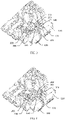
- Fig. 1 is an exploded view showing a part of an automatic transfer switching equipment 1 including a state indicating module 100 viewed from the outside.
- the automatic transfer switching equipment 1 includes a body 200 of the automatic transfer switching equipment 1 and one or more state indicating modules 100 attached to the body 200 of the automatic transfer switching equipment 1.
- Fig. 2 is an exploded perspective view showing the part of the automatic transfer switching equipment 1 and the structure of the state indicating module according to 100, viewed from below.
- the automatic transfer switching equipment 1 includes a first upper driving rod 201, a first lower driving rod 202, a second upper driving rod 203, and a second lower driving rod 204 which are parallel to each other, and are arranged in the body 200 of the automatic transfer switching equipment 1.
- the up and down direction here are described with reference to Figs. 2-9 , and are opposite to the up and down directions of the automatic transfer switching equipment 1 in normal use, that is, opposite to the up and down direction in Fig. 1 .
- Figs. 1 Referring to Figs.
- the state indicating module 100 includes a housing 110, a first micro switch assembly 120, and a second micro switch assembly 130.
- the housing 110 may include a base 111 and a cover 112 which are separable from each other.
- the first micro switch assembly 120 and the second micro switch assembly 130 can be installed in the base 111 or separated from the base 111. That is, the first micro switch assembly 120 and the second micro switch assembly 130 are detachably installed in the housing 110.
- the first micro switch assembly 120 includes a first micro switch button 121 the position of which indicating the on and off state of the first power supply; the second micro switch assembly 130 includes a second micro switch button 131 the position of which indicating the on and off state of the second power supply.
- the released position and the triggered position of the first micro switch button 121 and the second micro switch button 131 indicate different on and off states of the first power supply and the second power supply.
- the first micro switch button 121 and the second micro switch button 131 may be switched-on-triggered or switched-off-triggered. The specific implementation will be described in detail below.
- the state indicating module 100 further includes a transmission assembly, and the transmission assembly includes a first transmission assembly 140 and a second transmission assembly 150.
- the transmission assembly is movably mounted to the housing 110 and is configured to transmit the movement of the driving rods to the first micro switch button 121 and the second micro switch button 131.
- the first micro switch assembly 120 and the second micro switch assembly 130 include wiring terminals 122 and 132, respectively, configured to output a signal indicating the on and off state of the automatic transfer switching equipment 1 through wiring in response respectively to the positions of the first micro switch button 121 and the second micro switch button 131.
- the first micro switch button 121, the second micro switch button 131 and the wiring terminals are all arranged in the first micro switch assembly 120 and the second micro switch assembly 130, so that the first micro switch assembly 120 and the second micro switch assembly 130 can be installed in the housing 110 of the state indicating module 100 after being wired, which is convenient for wiring and maintenance.
- the state indicating module 100 may include a hook 113.
- the body 200 of the automatic transfer switching equipment 1 includes a corresponding slot 114.
- the state indicating module 100 is assembled to the automatic transfer switching equipment 1 through the cooperation of the hook 113 and the slot 114. The assembling is thus simple and quick.
- the state indicating module 100 also includes a slot 114 corresponding to the hook 113, that is, the same slot 114 as the slot 114 on the body 200 of the automatic transfer switching equipment 1, so that a next state indicating module 100 can be assembled to a previous one.
- a plurality of the state indicating module 100 can be assembled to the body 200 of the automatic transfer switching equipment 1 according to user needs.
- a pushing rod of the previous state indicating module 100 is used to actuate a pushing rod of the next state indicating module 100, so as to gradually transfer the movement of the driving rods in the body 200 backward.
- Each state indicating module 100 can output a set of on and off information of the automatic transfer switching equipment 1.
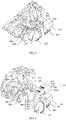
- Fig. 2 is an exploded perspective view showing the part of the automatic transfer switching equipment 1 and the structure of the state indicating module 100, viewed from below.
- the first transmission assembly 140 of the state indicating module 100 may include a first pushing rod 141.
- the first pushing rod 141 extends along the driving direction of the first lower driving rod 202 on the plane of the first lower driving rod 202 (seen more clearly in Figs. 3-5 ), is linearly movably mounted to the housing 110 in the extending direction, and includes a first protrusion 1411 protruding upward from the rod body of the first pushing rod 141.
- the end of the first pushing rod 141 adjacent to the first lower driving rod 202 has an arc shape, so that a linear end of the first lower driving rod 202 is convenient to contact with the arc end of the first pushing rod 141, and transmit the linear movement of the lower driving rod 202 to the first pushing rod 141, pushing the first pushing rod 141 to perform linear movement.
- the first transmission assembly 140 of the state indicating module 100 may further include a first oscillating rod 142, which is rotatably mounted to the housing 110 about a rotation axis.
- the first oscillating rod 142 may include a first actuating portion 1421 extending outward from the rod body of the first oscillating rod 142.
- the first actuating portion 1421 is configured to actuate the first micro switch button 121 when the first oscillating rod 142 is in the actuating position and to release the first micro switch button 121 when the first oscillating rod 142 is in the initial position.
- the rotation axis of the first oscillating rod 142 is perpendicular to the extending direction of the first pushing rod 141.
- the first transmission assembly 140 of the state indicating module 100 according to the first embodiment may further include a first return spring 143 configured to act on the first oscillating rod 142 with a return elastic force.
- the first return spring 143 according to the first embodiment is a torsion spring, and is configured to apply an elastic force to the first oscillating rod 142 to restore it to the initial position.
- the structure of the second transmission assembly 150 of the state indicating module 100 is similar to that of the first transmission assembly 140, and includes: a second pushing rod 151, which extends along the driving direction of the second upper driving rod 203 on the plane of the second upper driving rod 203, is linearly movably mounted to the housing 110 in the extending direction, and includes a second protrusion 1511 protruding upward from the rod body of the second pushing rod 151; a second oscillating rod 152, which is rotatably mounted to the housing 110 around a rotation axis, and includes a second actuating portion 1521 extending outward from the rod body of the second oscillating rod 152, the rotation axis of the second oscillating rod 152 is perpendicular to the extending direction of the second pushing rod 151; and a second return spring 153, which is configured to act on the second oscillating rod 152 with a return elastic force. It will not be described in detail here.
- the first power supply and the second power supply are both switched off at this time, so the first upper driving rod 201 and the second lower driving rod 204 are in the driving position, and the first lower driving rod 202 and the second upper driving rod 203 are in the initial position.
- the first pushing rod 141 extends along the driving direction of the first lower driving rod 202 on the plane of the first lower driving rod 202, that is, aligned with the first lower driving rod 202, and the first lower driving rod 202 is in the initial position, the first pushing rod 141 is not pushed and is in the initial position, so that the first oscillating rod 142 and the first actuating portion 1421 thereon are also in the initial position, and thereby the first micro switch button 121 is in the released position, outputting a signal indicating the first power supply is switched off.
- the second pushing rod 151 extends along the driving direction of the second upper driving rod 203 on the plane of the second upper driving rod 203, that is, aligned with the second upper driving rod 203, and the second upper driving rod 203 is in the initial position, the second pushing rod 151 is not pushed and is in the initial position, so that the second oscillating rod 152 and the second actuating portion 1521 thereon are also in the initial position, and thereby the second micro switch button 131 is in the released position, outputting a signal indicating the second power supply is switched off.
- the first power supply transfers from switched off to switched on at this time, so the first lower driving rod 202 moves from the initial position to the driving position.
- the first lower driving rod 202 contacts and drives the first pushing rod 141 aligned with the first lower driving rod 202 to move linearly
- the first protrusion 1411 on the first pushing rod 141 contacts and drives the first oscillating rod 142 to rotate
- the first actuating portion 1421 on the first oscillating rod 142 actuates the first micro switch button 121 to the triggered position where the first micro switch button 121 is depressed, outputting a signal indicating the first power supply is switched on.
- the second micro switch button 131 since the second power supply is still off and the second upper driving rod 203 is still in the initial position, the second micro switch button 131 is not actuated, outputting a signal indicating the second power supply is switched off.
- the second power supply transfers from switched off to switched on at this time, so the second upper driving rod 203 moves from the initial position to the driving position.
- the second upper driving rod 203 contacts and drives the second pushing rod 151 aligned with the second upper driving rod 203 to move linearly
- the second protrusion 1511 on the second pushing rod 151 contacts and drives the second oscillating rod 152 to rotate
- the second actuating portion 1521 on the second oscillating rod 152 actuates the second micro switch button 131 to the triggered position where the second micro switch button 151 is depressed, outputting a signal indicating the second power supply is switched on.
- the first lower driving rod 202 moves from the driving position back to the initial position, and the first oscillating rod 142 returns to the initial position under the action of elastic force of the first return spring 143 thereby bringing the first pushing rod 141 to return to the initial position through the first protrusion 1411 where the first micro switch button 121 is released and returns to the released position under the action of its return force, outputting a signal indicating the first power supply is switched off.
- the state indicating module 100 is switched-on-triggered.
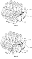
- Fig. 6 is an exploded perspective view showing the part of the power automatic transfer switch and the structure of the state indicating module 100 according to a second embodiment , viewed from below.
- the first transmission assembly 140 of the state indicating module 100 according to the second embodiment may include a first pushing rod 141.
- the first pushing rod 141 extends along the driving direction of the second lower driving rod 204 on the plane of the second lower driving rod 204 (seen more clearly in Figs. 7-9 ) and linearly movably mounted to the housing 110 in the extending direction.
- the end of the first pushing rod 141 adjacent to the first lower driving rod 202 has an arc shape, so that the linear end of the first lower driving rod 202 is convenient to contact with the arc end of the first pushing rod 141, and transmit the linear movement of the first lower driving rod 202 to the first pushing rod 141, pushing the first pushing rod 141 to perform linear movement.
- the first pushing rod 141 includes a first protrusion 1411 protruding downward from the rod body of the first pushing rod 141, and the first protrusion 1411 includes a slope surface.
- the first transmission assembly 140 of the state indicating module 100 according to the second embodiment may further include a first sliding member 144 that is linearly movably mounted to the housing 110 in the up and down direction.
- the first sliding member 144 includes a slope surface that cooperates with the slope surface of the first protrusion 1411 of the first pushing rod 141, so that the linear movement of the first pushing rod 141 in its extension direction can be converted into the linear movement of the first sliding member 144 in the up and down direction.
- the first sliding member 144 further includes a first actuating portion 1421 configured to actuate the first micro switch button 121.
- the first transmission assembly 140 of the state indicating module 100 according to the second embodiment may further include a first return spring 143 configured to act on the first pushing rod 141 with a return elastic force. As shown in Fig. 6 , the first return spring 143 according to the second embodiment is a compressed spring and is configured to apply an elastic force to the first pushing rod 141 to restore it to the initial position.
- the structure of the second transmission assembly 150 of the state indicating module 100 is similar to that of the first transmission assembly 140, and includes: a second pushing rod 151 extending along a driving direction of the first upper driving rod 201 on a plane of the first upper driving rod 201, linearly movably mounted to the housing 110 in the extending direction, and including a second protrusion 1511 downwardly protruding from the rod body of the first pushing rod 141, the second protrusion 1511 including a slope surface; a second sliding member 154 linearly movably mounted to the housing 110 in the up and down direction, including an slope surface cooperating with the slope surface of the second protrusion 1511 so that the linear movement of the second pushing rod 151 in its extending direction can be converted to a linear movement of the second sliding member 1554 in the up and down direction, and further including a second actuating portion 1521 configured to actuate the second micro switch button 131; and a second return spring 153 configured to act a return elastic force on the second pushing rod 151
- the relative position of the first transmission assembly 140 and the second transmission assembly 150 according to the second embodiment is opposite, and relative position of the first micro switch assembly 120 and the second transmission assembly 130 according to the second embodiment is also opposite.
- the first power supply and the second power supply are both switched off at this time, so the first upper driving rod 201 and the second lower driving rod 204 are in the driving position, and the first lower driving rod 202 and the second upper driving rod 203 are in the initial position.
- the first pushing rod 141 extends along the driving direction of the second lower driving rod 204 on the plane of the second lower driving rod 204, that is, aligned with the second lower driving rod 204, and the second lower driving rod 204 is in the driving position, the first pushing rod 141 is pushed to the actuating position, so that the first sliding member 144 is pushed by the first pushing rod 141 to move downwardly to the actuating position through the cooperation of the slope surface of the first protrusion 1411 and the slope surface of the first sliding member 144, the first actuating portion 1421 of the first sliding member 144 is also in the actuating position, and thereby the first micro switch button 121 is in the triggering position, outputting a signal indicating the first power supply is switched off.
- the second pushing rod 151 extends along the driving direction of the first upper driving rod 201 on the plane of the first upper driving rod 201, that is, aligned with the first upper driving rod 201, and the first upper driving rod 201 is in the actuating position, the second pushing rod 151 is pushed to the actuating position, so that the second sliding member 154 is pushed by the second pushing rod 151 to move downwardly to the actuating position through the cooperation of the slope surface of the second protrusion 1511 and the slope surface of the second sliding member 154, the second actuating portion 1521 of the second sliding member 154 is also in the actuating position, and thereby the second micro switch button 131 is in the triggering position, outputting a signal indicating the second power supply is switched off.
- the first power supply transfers from switched off to switched on at this time, so the second lower driving rod 204 moves from the driving position back to the initial position.
- the first pushing rod 141 returns to the initial position under the action of the elastic force of the first return spring 143, and the first micro switch button 121 and the first sliding member 144 return to the released position and the initial position respectively under the action of the return force of the first micro switch button 121, outputting a signal indicating the first power supply is switched on.
- the second micro switch button 131 since the second power supply is still off and the first upper driving rod 201 is still in the driving position, the second micro switch button 131 is still actuated and is in the triggered position, outputting a signal indicating the second power supply is switched off.
- the second power supply transfers from switched off to switched on at this time, so the first upper driving rod 201 moves from the driving position back to the initial position.
- the second pushing rod 151 returns to the initial position under the action of the elastic force of the second return spring 153, and the second micro switch button 131 and the second sliding member 154 return to the released position and the initial position respectively under the action of the return force of the second micro switch button 131, outputting a signal indicating the second power supply is switched on.
- the second lower driving rod 204 moves from the initial position to the driving position, and the second lower driving rod 204 contacts and drives the first pushing rod 141 aligned with the second lower driving rod 204 to perform a linear movement, so that the first sliding member 144 is pushed by the first pushing rod 141 to move downwardly to the actuating position through the cooperation of the slope surface of the first protrusion 1411 and the slope surface of the first sliding member 144, and the first actuating portion 1421 of the first sliding member 144 presses down the first micro switch button 121 to the triggered position, outputting a signal indicating the first power supply is switched off.
- the second power supply transfers from switched on to switched off, the first upper driving rod 201 moves from the initial position to the driving position, and the first upper driving rod 201 contacts and drives the second pushing rod 151 aligned with the first upper driving rod 201 to perform a linear movement, so that the second sliding member 154 is pushed by the second pushing rod 151 to move downwardly to the actuating position through the cooperation of the slope surface of the second protrusion 1511 and the slope surface of the second sliding member 154, and the second actuating portion 1521 of the second sliding member 154 presses down the second micro switch button 131 to the triggered position, outputting a signal indicating the second power supply is switched off.
- the first micro switch button 121 is still actuated and is in the triggered position, outputting a signal indicating the first power supply is switched off.
- the state indicating module 100 is switched-off-triggered.
- the micro switch of the state indicating module 100 is arranged in the state indicating module 100, which is convenient for installation and maintenance. And it is possible to provide one or more state indicating modules 100 in an expandable manner according to customer needs, thereby outputting one or more states indicating module signal.
- the state indicating module is small in size, easy to be installed and wired, and can be switched-on-triggered or switched-off-triggered according to the characteristics of the mechanism.
Landscapes
- Physics & Mathematics (AREA)
- Electromagnetism (AREA)
- Push-Button Switches (AREA)
Claims (8)
- Automatische Umschaltvorrichtung (1), die umfasst:einen Körper (200) der automatischen Umschaltvorrichtung (1); und wobeidie automatische Umschaltvorrichtung (1) ferner eine erste obere Antriebsstange (201), eine erste untere Antriebsstange (202), eine zweite obere Antriebsstange (203) und eine zweite untere Antriebsstange (204) umfasst, die parallel zueinander in dem Körper (200) der automatischen Umschaltvorrichtung (1) angeordnet sind, wenn eine erste Stromversorgung und eine zweite Stromversorgung beide ausgeschaltet sind, sich die erste obere Antriebsstange (201) und die zweite untere Antriebsstange (204) in einer Antriebsposition befinden, und sich die erste untere Antriebsstange (202) und die zweite obere Antriebsstange (203) in einer Ausgangsposition befinden; wenn die erste Stromversorgung eingeschaltet ist, sich die erste obere Antriebsstange (201) und die erste untere Antriebsstange (202) in der Antriebsposition befinden, sich die zweite obere Antriebsstange (203) und die zweite untere Antriebsstange (204) in der Ausgangsposition befinden; wenn die zweite Stromversorgung eingeschaltet ist, sich die zweite obere Antriebsstange (203) und die zweite untere Antriebsstange (204) in der Antriebsposition befinden und sich die erste obere Antriebsstange (201) und die erste untere Antriebsstange (202) in der Ausgangsposition befinden, gekennzeichnet durch ein oder mehrere Zustandsanzeigemodule (100), die an dem Körper (200) der automatischen Umschaltvorrichtung (1) angebracht sind, wobei das Zustandsanzeigemodul (100) verwendet wird, um einen Ein- und Ausschaltzustand der automatischen Umschaltvorrichtung anzuzeigen,wobei das Zustandsanzeigemodul (100) umfasst:ein Gehäuse (110), das abnehmbar an dem Körper (200) der automatischen Umschaltvorrichtung (1) montiert ist;eine erste Mikroschalteranordnung (120), die abnehmbar in dem Gehäuse (110) installiert ist und einen ersten Mikroschalterknopf (121) umfasst, wobei eine Position des ersten Mikroschalterknopfes (121) einen Ein- und Ausschaltzustand der ersten Stromversorgung anzeigt;eine zweite Mikroschalteranordnung (130), die abnehmbar in dem Gehäuse (110) installiert ist und einen zweiten Mikroschalterknopf (131) umfasst, wobei eine Position des zweiten Mikroschalterknopfes einen Ein- und Ausschaltzustand der zweiten Stromversorgung anzeigt;eine Getriebeanordnung, die beweglich an dem Gehäuse (110) angebracht und so konfiguriert ist, dass sie eine Bewegung der Antriebsstangen auf den ersten Mikroschalterknopf (121) und den zweiten Mikroschalterknopf überträgt,wobei die erste Mikroschalteranordnung (120) und die zweite Mikroschalteranordnung (130) jeweils einen Verdrahtungsanschluss (122, 132) umfassen, der so konfiguriert ist, dass er ein Signal, das den Ein- und Ausschaltzustand der automatischen Umschaltvorrichtung (1) anzeigt, in Reaktion auf die Positionen des ersten Mikroschalterknopfes (121) bzw. des zweiten Mikroschalterknopfes (131) durch eine Verdrahtung ausgibt.
- Automatische Umschaltvorrichtung (1) nach Anspruch 1, dadurch gekennzeichnet, dass sich der erste Mikroschalterknopf (121) in einer freigegebenen Position befindet, wenn die erste Stromversorgung ausgeschaltet ist, und dass sich der erste Mikroschalterknopf (121) in einer ausgelösten Position befindet, wenn die erste Stromversorgung eingeschaltet ist; dass sich der zweite Mikroschalterknopf in einer freigegebenen Position befindet, wenn die zweite Stromversorgung ausgeschaltet ist, und dass sich der zweite Mikroschalterknopf in einer ausgelösten Position befindet, wenn die zweite Stromversorgung eingeschaltet ist.
- Automatische Umschaltvorrichtung (1) nach Anspruch 2, dadurch gekennzeichnet, dass die Getriebeanordnung eine erste Getriebeanordnung (140) und eine zweite Getriebeanordnung (150) umfasst,wobei die erste Getriebeanordnung (140) umfasst:eine erste Schubstange (141), die sich entlang einer Antriebsrichtung der ersten unteren Antriebsstange (202) auf einer Ebene der ersten unteren Antriebsstange (202) erstreckt, linear beweglich an dem Gehäuse (110) in einer Erstreckungsrichtung angebracht ist und einen ersten Vorsprung (1411) umfasst, der von einem Stangenkörper der ersten Schubstange (141) nach oben vorsteht;eine erste oszillierende Stange (142), die um eine Drehachse drehbar am Gehäuse (110) angebracht ist und einen ersten Betätigungsabschnitt (1421) umfasst, der sich von einem Stangenkörper der ersten oszillierenden Stange (142) nach außen erstreckt, wobei die Drehachse der ersten oszillierenden Stange (142) senkrecht zur Erstreckungsrichtung der ersten Schubstange (141) verläuft; undeine erste Rückstellfeder (143), die so konfiguriert ist, dass sie eine elastische Rückstellkraft auf die erste oszillierende Stange (142) ausübt,wobei, wenn die erste Stromversorgung eingeschaltet wird, sich die erste untere Antriebsstange (202) in Richtung der Antriebsposition bewegt, die erste Schubstange (141) berührt und zu einer linearen Bewegung antreibt, und gleichzeitig der erste Vorsprung (1411) an der ersten Schubstange (141) die erste oszillierende Stange (142) berührt und zur Drehung antreibt, und der erste Betätigungsabschnitt (1421) an der ersten oszillierenden Stange (142) den ersten Mikroschalterknopf (121) in die ausgelöste Position betätigt; wenn die erste Stromversorgung ausgeschaltet wird, sich die erste untere Antriebsstange (202) in die Ausgangsposition bewegt, die erste oszillierende Stange (142) unter der Wirkung der elastischen Kraft der ersten Rückstellfeder (143) in die Ausgangsposition zurückkehrt, wodurch die erste Schubstange (141) durch den ersten Vorsprung (1411) dazu gebracht wird, in die Ausgangsposition zurückzukehren, und der erste Mikroschalterknopf (121) unter der Wirkung seiner Rückstellkraft in die freigegebene Position zurückkehrt,und wobei die zweite Getriebeanordnung (150) umfasst:eine zweite Schubstange (151), die sich entlang einer Antriebsrichtung der zweiten oberen Antriebsstange (203) auf einer Ebene der zweiten oberen Antriebsstange (203) erstreckt, linear beweglich an dem Gehäuse (110) in einer Erstreckungsrichtung angebracht ist und einen zweiten Vorsprung (1511) umfasst, der von einem Stangenkörper der zweiten Schubstange (151) nach oben vorsteht;eine zweite oszillierende Stange (152), die um eine Drehachse drehbar am Gehäuse (110) angebracht ist und einen zweiten Betätigungsabschnitt (1521) umfasst, der sich von einem Stangenkörper der zweiten oszillierenden Stange (152) nach außen erstreckt, wobei die Drehachse der zweiten oszillierenden Stange (152) senkrecht zur Erstreckungsrichtung der zweiten Schubstange (151) verläuft; undeine zweite Rückstellfeder (153), die so konfiguriert ist, dass sie eine elastische Rückstellkraft auf die zweite oszillierende Stange (152) ausübt,wobei, wenn die zweite Stromversorgung eingeschaltet wird, sich die zweite obere Antriebsstange (203) in Richtung der Antriebsposition bewegt, die zweite Schubstange (151) berührt und zu einer linearen Bewegung antreibt, und gleichzeitig der zweite Vorsprung (1511) an der zweiten Schubstange (151) die zweite oszillierende Stange (152) berührt und zur Drehung antreibt, und der zweite Betätigungsabschnitt (1521) an der zweiten oszillierenden Stange (152) den zweiten Mikroschalterknopf in die ausgelöste Position betätigt; wenn die zweite Stromversorgung ausgeschaltet wird, sich die zweite obere Antriebsstange (203) in die Ausgangsposition bewegt, die zweite oszillierende Stange (152) unter der Wirkung der elastischen Kraft der zweiten Rückstellfeder (153) in die Ausgangsposition zurückkehrt, wodurch die zweite Schubstange (151) durch den zweiten Vorsprung (1511) dazu gebracht wird, in die Ausgangsposition zurückzukehren, und der zweite Mikroschalterknopf unter der Wirkung seiner Rückstellkraft in die freigegebene Position zurückkehrt.
- Automatische Umschaltvorrichtung (1) nach Anspruch 1, dadurch gekennzeichnet, dass sich der erste Mikroschalterknopf (121) in einer ausgelösten Position befindet, wenn die erste Stromversorgung ausgeschaltet ist, und dass sich der erste Mikroschalterknopf (121) in einer freigegebenen Position befindet, wenn die erste Stromversorgung eingeschaltet ist; dass sich der zweite Mikroschalterknopf in einer ausgelösten Position befindet, wenn die zweite Stromversorgung ausgeschaltet ist, und dass sich der zweite Mikroschalterknopf in einer freigegebenen Position befindet, wenn die zweite Stromversorgung eingeschaltet ist.
- Automatische Umschaltvorrichtung (1) nach Anspruch 4, dadurch gekennzeichnet, dass die Getriebeanordnung eine erste Getriebeanordnung (140) und eine zweite Getriebeanordnung (150) umfasst,wobei die erste Getriebeanordnung (140) umfasst:eine erste Schubstange (141), die sich entlang einer Antriebsrichtung der zweiten unteren Antriebsstange (204) auf einer Ebene der zweiten unteren Antriebsstange (204) erstreckt, linear beweglich an dem Gehäuse (110) in einer Erstreckungsrichtung angebracht ist und einen ersten Vorsprung (1411) umfasst, der von einem Stangenkörper der ersten Schubstange (141) nach unten vorsteht, wobei der erste Vorsprung (1411) eine geneigte Fläche aufweist;ein erstes Gleitelement (144), das an dem Gehäuse (110) in einer Aufwärts- und Abwärtsrichtung linear beweglich angebracht ist und eine geneigte Fläche aufweist, die mit der geneigten Fläche des ersten Vorsprungs (1411) zusammenwirkt, so dass die lineare Bewegung der ersten Schubstange (141) in ihrer Erstreckungsrichtung in eine lineare Bewegung des ersten Gleitelements (144) in der Aufwärts- und Abwärtsrichtung umgewandelt werden kann, und ferner einen ersten Betätigungsabschnitt (1421) aufweist, der so konfiguriert ist, dass er den ersten Mikroschalterknopf (121) betätigt; undeine erste Rückstellfeder (143), die so konfiguriert ist, dass sie eine elastische Rückstellkraft auf die erste Schubstange (141) ausübt,wobei, wenn die erste Stromversorgung ausgeschaltet wird, sich die zweite untere Antriebsstange (204) in Richtung der Antriebsposition bewegt, die erste Schubstange (141) berührt und zu einer linearen Bewegung antreibt, und das erste Gleitelement (144) drückt, um durch ein Zusammenwirken der geneigten Fläche des ersten Vorsprungs (1411) und der geneigten Fläche des ersten Gleitelements (144) nach unten zu gleiten, so dass der erste Betätigungsabschnitt (1421) des ersten Gleitelements (144) den ersten Mikroschalterknopf (121) in die ausgelöste Position betätigt; wenn die erste Stromversorgung eingeschaltet wird, sich die zweite untere Antriebsstange (204) in die Ausgangsposition bewegt, die erste Schubstange (141) unter der Wirkung der elastischen Kraft der ersten Rückstellfeder (143) in die Ausgangsposition zurückkehrt, und der erste Mikroschalterknopf (121) und das erste Gleitelement (144) unter einer Rückstellkraft des ersten Mikroschalterknopfes (121) in die freigegebene Position bzw. in die Ausgangsposition zurückkehren,und wobei die zweite Getriebeanordnung (150) umfasst:eine zweite Schubstange (151), die sich entlang einer Antriebsrichtung der ersten oberen Antriebsstange (201) auf einer Ebene der ersten oberen Antriebsstange (201) erstreckt, linear beweglich an dem Gehäuse (110) in einer Erstreckungsrichtung angebracht ist und einen zweiten Vorsprung (1511) umfasst, der von einem Stangenkörper der ersten Schubstange (141) nach unten vorsteht, wobei der zweite Vorsprung (1511) eine geneigte Fläche aufweist;ein zweites Gleitelement (154), das an dem Gehäuse (110) in einer Aufwärts- und Abwärtsrichtung linear beweglich angebracht ist und eine geneigte Fläche aufweist, die mit der geneigten Fläche des zweiten Vorsprungs (1511) zusammenwirkt, so dass die lineare Bewegung der zweiten Schubstange (151) in ihrer Erstreckungsrichtung in eine lineare Bewegung des zweiten Gleitelements (154) in der Aufwärts- und Abwärtsrichtung umgewandelt werden kann, und ferner einen zweiten Betätigungsabschnitt (1521) aufweist, der so konfiguriert ist, dass er den zweiten Mikroschalterknopf betätigt; undeine zweite Rückstellfeder (153), die so konfiguriert ist, dass sie eine elastische Rückstellkraft auf die zweite Schubstange (151) ausübt,wobei, wenn die zweite Stromversorgung ausgeschaltet wird, sich die erste obere Antriebsstange (201) in Richtung der Antriebsposition bewegt, die zweite Schubstange (151) berührt und zu einer linearen Bewegung antreibt, und das zweite Gleitelement (154) drückt, um durch ein Zusammenwirken der geneigten Fläche des zweiten Vorsprungs (1511) und der geneigten Fläche des zweiten Gleitelements (154) nach unten zu gleiten, so dass der zweite Betätigungsabschnitt (1521) des zweiten Gleitelements (154) den zweiten Mikroschalterknopf in die ausgelöste Position betätigt; wenn die zweite Stromversorgung eingeschaltet wird, sich die erste obere Antriebsstange (201) in die Ausgangsposition bewegt, die zweite Schubstange (151) unter der Wirkung der elastischen Kraft der zweiten Rückstellfeder (153) in die Ausgangsposition zurückkehrt, und der zweite Mikroschalterknopf und das zweite Gleitelement (154) unter einer Rückstellkraft des zweiten Mikroschalterknopfes in die freigegebene Position bzw. in die Ausgangsposition zurückkehren.
- Automatische Umschaltvorrichtung (1) nach einem der Ansprüche 1 bis 5, dadurch gekennzeichnet, dass das Zustandsanzeigemodul (100) einen Haken (113) umfasst, der Körper (200) der automatischen Umschaltvorrichtung (1) einen entsprechenden Schlitz (114) umfasst und das Zustandsanzeigemodul (100) durch Zusammenwirken des Hakens (113) und des Schlitzes (114) mit dem Körper (200) der automatischen Umschaltvorrichtung (1) zusammengebaut ist.
- Automatische Umschaltvorrichtung (1) nach Anspruch 6, dadurch gekennzeichnet, dass das Zustandsanzeigemodul (100) ferner einen Schlitz (114) aufweist, der dem Haken (113) entspricht, so dass ein nächstes Zustandsanzeigemodul (100) an ein vorhergehendes Zustandsanzeigemodul (100) montiert werden kann, wodurch eine Vielzahl von Zustandsanzeigemodulen (100) an der automatischen Umschaltvorrichtung (1) entsprechend den Bedürfnissen des Benutzers montiert werden kann.
- Automatische Umschaltvorrichtung (1) nach einem der Ansprüche 1 bis 5, dadurch gekennzeichnet, dass das Gehäuse (110) einen Sockel (111) und einen Deckel (112) umfasst, die voneinander getrennt werden können, und dass, wenn der Sockel (111) und der Deckel (112) getrennt sind, die erste Mikroschalteranordnung (120), die verdrahtet wurde, und die zweite Mikroschalteranordnung, die verdrahtet wurde, in das Gehäuse (110) eingebaut werden können.
Applications Claiming Priority (1)
| Application Number | Priority Date | Filing Date | Title |
|---|---|---|---|
| CN201921655891.9U CN210325574U (zh) | 2019-09-30 | 2019-09-30 | 状态指示模块和双电源自动转换开关 |
Publications (2)
| Publication Number | Publication Date |
|---|---|
| EP3799089A1 EP3799089A1 (de) | 2021-03-31 |
| EP3799089B1 true EP3799089B1 (de) | 2023-01-04 |
Family
ID=70133357
Family Applications (1)
| Application Number | Title | Priority Date | Filing Date |
|---|---|---|---|
| EP20306130.4A Active EP3799089B1 (de) | 2019-09-30 | 2020-09-30 | Zustandsanzeigemodul und automatische übertragungsvermittlungseinrichtung |
Country Status (3)
| Country | Link |
|---|---|
| EP (1) | EP3799089B1 (de) |
| CN (1) | CN210325574U (de) |
| AU (1) | AU2020244486B2 (de) |
Families Citing this family (1)
| Publication number | Priority date | Publication date | Assignee | Title |
|---|---|---|---|---|
| CN114413936A (zh) * | 2021-11-09 | 2022-04-29 | 上海宇航系统工程研究所 | 一种旋转式、多角度解锁到位信号触发装置 |
Family Cites Families (5)
| Publication number | Priority date | Publication date | Assignee | Title |
|---|---|---|---|---|
| US4021678A (en) * | 1976-01-19 | 1977-05-03 | Automatic Switch Company | Automatic transfer switch |
| CN106783284B (zh) * | 2015-11-24 | 2018-12-21 | 施耐德电气工业公司 | 双电源转换开关 |
| CN206877854U (zh) * | 2017-03-31 | 2018-01-12 | 施耐德电器工业公司 | 双电源自动转换开关 |
| CN208142045U (zh) * | 2018-05-04 | 2018-11-23 | 施耐德电器工业公司 | 双电源转换开关及其切换机构 |
| CN209071158U (zh) * | 2019-01-10 | 2019-07-05 | 常熟开关制造有限公司(原常熟开关厂) | 一种自动转换开关的指示辅助装置 |
-
2019
- 2019-09-30 CN CN201921655891.9U patent/CN210325574U/zh active Active
-
2020
- 2020-09-30 EP EP20306130.4A patent/EP3799089B1/de active Active
- 2020-09-30 AU AU2020244486A patent/AU2020244486B2/en active Active
Also Published As
| Publication number | Publication date |
|---|---|
| CN210325574U (zh) | 2020-04-14 |
| EP3799089A1 (de) | 2021-03-31 |
| AU2020244486B2 (en) | 2022-03-10 |
| AU2020244486A1 (en) | 2021-04-15 |
Similar Documents
| Publication | Publication Date | Title |
|---|---|---|
| US3800104A (en) | Low profile keyboard switch assembly with snap action cantilever contact | |
| US4659881A (en) | Multidome multistage switch assembly | |
| AU2005203661B2 (en) | Button fastening device with circuit actuating capability | |
| US5701110A (en) | Circuit breaker accessory module | |
| EP2149892B1 (de) | Miniaturschalter | |
| EP1785683A2 (de) | Integrierter Aktuator für eine Abgabeeinheit eines Kühlschranks | |
| EP3799089B1 (de) | Zustandsanzeigemodul und automatische übertragungsvermittlungseinrichtung | |
| AU2020381882B2 (en) | Buckle | |
| EP0043618B1 (de) | Druckknopfschalter | |
| AU2020244488B2 (en) | Indicating device of dual-power automatic transfer switch and dual-power automatic transfer switch | |
| US5836441A (en) | Circuit breaker accessory module actuators | |
| EP0336797A1 (de) | Elektrischer Tastenschalter | |
| CN111161963B (zh) | 用于紧急停止装置的带有安全附件解决方案的开关组件 | |
| US7009131B2 (en) | Switch assembly | |
| CN211629007U (zh) | 一种小型断路器及信号反馈系统 | |
| JP2022552385A (ja) | マイクロスイッチ付きの磁気ラッチングリレー | |
| CN211125428U (zh) | 用于火灾报警控制面板的双按钮装置 | |
| CN116453892A (zh) | 一种具有触觉反馈的自锁式带按钮开关信号灯 | |
| CN110931319B (zh) | 一种并联控制断路器的操作结构 | |
| CN211980476U (zh) | 一键双控智能开关 | |
| CN213277974U (zh) | 用于断路器的脱扣报警附件及具有其的断路器 | |
| CN110931318B (zh) | 一种并联控制断路器的执行机构 | |
| JP2003151404A (ja) | 多方向入力装置 | |
| JPS63155518A (ja) | 多機能スイツチ構造 | |
| RU1775740C (ru) | Клавиатура |
Legal Events
| Date | Code | Title | Description |
|---|---|---|---|
| PUAI | Public reference made under article 153(3) epc to a published international application that has entered the european phase |
Free format text: ORIGINAL CODE: 0009012 |
|
| STAA | Information on the status of an ep patent application or granted ep patent |
Free format text: STATUS: THE APPLICATION HAS BEEN PUBLISHED |
|
| AK | Designated contracting states |
Kind code of ref document: A1 Designated state(s): AL AT BE BG CH CY CZ DE DK EE ES FI FR GB GR HR HU IE IS IT LI LT LU LV MC MK MT NL NO PL PT RO RS SE SI SK SM TR |
|
| AX | Request for extension of the european patent |
Extension state: BA ME |
|
| STAA | Information on the status of an ep patent application or granted ep patent |
Free format text: STATUS: REQUEST FOR EXAMINATION WAS MADE |
|
| 17P | Request for examination filed |
Effective date: 20210930 |
|
| RBV | Designated contracting states (corrected) |
Designated state(s): AL AT BE BG CH CY CZ DE DK EE ES FI FR GB GR HR HU IE IS IT LI LT LU LV MC MK MT NL NO PL PT RO RS SE SI SK SM TR |
|
| GRAP | Despatch of communication of intention to grant a patent |
Free format text: ORIGINAL CODE: EPIDOSNIGR1 |
|
| STAA | Information on the status of an ep patent application or granted ep patent |
Free format text: STATUS: GRANT OF PATENT IS INTENDED |
|
| RIC1 | Information provided on ipc code assigned before grant |
Ipc: H01H 9/16 20060101AFI20220714BHEP |
|
| INTG | Intention to grant announced |
Effective date: 20220808 |
|
| GRAS | Grant fee paid |
Free format text: ORIGINAL CODE: EPIDOSNIGR3 |
|
| GRAA | (expected) grant |
Free format text: ORIGINAL CODE: 0009210 |
|
| STAA | Information on the status of an ep patent application or granted ep patent |
Free format text: STATUS: THE PATENT HAS BEEN GRANTED |
|
| AK | Designated contracting states |
Kind code of ref document: B1 Designated state(s): AL AT BE BG CH CY CZ DE DK EE ES FI FR GB GR HR HU IE IS IT LI LT LU LV MC MK MT NL NO PL PT RO RS SE SI SK SM TR |
|
| REG | Reference to a national code |
Ref country code: GB Ref legal event code: FG4D |
|
| REG | Reference to a national code |
Ref country code: DE Ref legal event code: R096 Ref document number: 602020007361 Country of ref document: DE |
|
| REG | Reference to a national code |
Ref country code: CH Ref legal event code: EP |
|
| REG | Reference to a national code |
Ref country code: AT Ref legal event code: REF Ref document number: 1542533 Country of ref document: AT Kind code of ref document: T Effective date: 20230115 |
|
| REG | Reference to a national code |
Ref country code: IE Ref legal event code: FG4D |
|
| REG | Reference to a national code |
Ref country code: LT Ref legal event code: MG9D |
|
| REG | Reference to a national code |
Ref country code: NL Ref legal event code: MP Effective date: 20230104 |
|
| REG | Reference to a national code |
Ref country code: AT Ref legal event code: MK05 Ref document number: 1542533 Country of ref document: AT Kind code of ref document: T Effective date: 20230104 |
|
| PG25 | Lapsed in a contracting state [announced via postgrant information from national office to epo] |
Ref country code: NL Free format text: LAPSE BECAUSE OF FAILURE TO SUBMIT A TRANSLATION OF THE DESCRIPTION OR TO PAY THE FEE WITHIN THE PRESCRIBED TIME-LIMIT Effective date: 20230104 |
|
| PG25 | Lapsed in a contracting state [announced via postgrant information from national office to epo] |
Ref country code: RS Free format text: LAPSE BECAUSE OF FAILURE TO SUBMIT A TRANSLATION OF THE DESCRIPTION OR TO PAY THE FEE WITHIN THE PRESCRIBED TIME-LIMIT Effective date: 20230104 Ref country code: PT Free format text: LAPSE BECAUSE OF FAILURE TO SUBMIT A TRANSLATION OF THE DESCRIPTION OR TO PAY THE FEE WITHIN THE PRESCRIBED TIME-LIMIT Effective date: 20230504 Ref country code: NO Free format text: LAPSE BECAUSE OF FAILURE TO SUBMIT A TRANSLATION OF THE DESCRIPTION OR TO PAY THE FEE WITHIN THE PRESCRIBED TIME-LIMIT Effective date: 20230404 Ref country code: LV Free format text: LAPSE BECAUSE OF FAILURE TO SUBMIT A TRANSLATION OF THE DESCRIPTION OR TO PAY THE FEE WITHIN THE PRESCRIBED TIME-LIMIT Effective date: 20230104 Ref country code: LT Free format text: LAPSE BECAUSE OF FAILURE TO SUBMIT A TRANSLATION OF THE DESCRIPTION OR TO PAY THE FEE WITHIN THE PRESCRIBED TIME-LIMIT Effective date: 20230104 Ref country code: HR Free format text: LAPSE BECAUSE OF FAILURE TO SUBMIT A TRANSLATION OF THE DESCRIPTION OR TO PAY THE FEE WITHIN THE PRESCRIBED TIME-LIMIT Effective date: 20230104 Ref country code: ES Free format text: LAPSE BECAUSE OF FAILURE TO SUBMIT A TRANSLATION OF THE DESCRIPTION OR TO PAY THE FEE WITHIN THE PRESCRIBED TIME-LIMIT Effective date: 20230104 Ref country code: AT Free format text: LAPSE BECAUSE OF FAILURE TO SUBMIT A TRANSLATION OF THE DESCRIPTION OR TO PAY THE FEE WITHIN THE PRESCRIBED TIME-LIMIT Effective date: 20230104 |
|
| PG25 | Lapsed in a contracting state [announced via postgrant information from national office to epo] |
Ref country code: SE Free format text: LAPSE BECAUSE OF FAILURE TO SUBMIT A TRANSLATION OF THE DESCRIPTION OR TO PAY THE FEE WITHIN THE PRESCRIBED TIME-LIMIT Effective date: 20230104 Ref country code: PL Free format text: LAPSE BECAUSE OF FAILURE TO SUBMIT A TRANSLATION OF THE DESCRIPTION OR TO PAY THE FEE WITHIN THE PRESCRIBED TIME-LIMIT Effective date: 20230104 Ref country code: IS Free format text: LAPSE BECAUSE OF FAILURE TO SUBMIT A TRANSLATION OF THE DESCRIPTION OR TO PAY THE FEE WITHIN THE PRESCRIBED TIME-LIMIT Effective date: 20230504 Ref country code: GR Free format text: LAPSE BECAUSE OF FAILURE TO SUBMIT A TRANSLATION OF THE DESCRIPTION OR TO PAY THE FEE WITHIN THE PRESCRIBED TIME-LIMIT Effective date: 20230405 Ref country code: FI Free format text: LAPSE BECAUSE OF FAILURE TO SUBMIT A TRANSLATION OF THE DESCRIPTION OR TO PAY THE FEE WITHIN THE PRESCRIBED TIME-LIMIT Effective date: 20230104 |
|
| REG | Reference to a national code |
Ref country code: DE Ref legal event code: R097 Ref document number: 602020007361 Country of ref document: DE |
|
| PG25 | Lapsed in a contracting state [announced via postgrant information from national office to epo] |
Ref country code: SM Free format text: LAPSE BECAUSE OF FAILURE TO SUBMIT A TRANSLATION OF THE DESCRIPTION OR TO PAY THE FEE WITHIN THE PRESCRIBED TIME-LIMIT Effective date: 20230104 Ref country code: RO Free format text: LAPSE BECAUSE OF FAILURE TO SUBMIT A TRANSLATION OF THE DESCRIPTION OR TO PAY THE FEE WITHIN THE PRESCRIBED TIME-LIMIT Effective date: 20230104 Ref country code: EE Free format text: LAPSE BECAUSE OF FAILURE TO SUBMIT A TRANSLATION OF THE DESCRIPTION OR TO PAY THE FEE WITHIN THE PRESCRIBED TIME-LIMIT Effective date: 20230104 Ref country code: DK Free format text: LAPSE BECAUSE OF FAILURE TO SUBMIT A TRANSLATION OF THE DESCRIPTION OR TO PAY THE FEE WITHIN THE PRESCRIBED TIME-LIMIT Effective date: 20230104 Ref country code: CZ Free format text: LAPSE BECAUSE OF FAILURE TO SUBMIT A TRANSLATION OF THE DESCRIPTION OR TO PAY THE FEE WITHIN THE PRESCRIBED TIME-LIMIT Effective date: 20230104 |
|
| PLBE | No opposition filed within time limit |
Free format text: ORIGINAL CODE: 0009261 |
|
| STAA | Information on the status of an ep patent application or granted ep patent |
Free format text: STATUS: NO OPPOSITION FILED WITHIN TIME LIMIT |
|
| PG25 | Lapsed in a contracting state [announced via postgrant information from national office to epo] |
Ref country code: SK Free format text: LAPSE BECAUSE OF FAILURE TO SUBMIT A TRANSLATION OF THE DESCRIPTION OR TO PAY THE FEE WITHIN THE PRESCRIBED TIME-LIMIT Effective date: 20230104 |
|
| PGFP | Annual fee paid to national office [announced via postgrant information from national office to epo] |
Ref country code: FR Payment date: 20230927 Year of fee payment: 4 Ref country code: DE Payment date: 20230911 Year of fee payment: 4 |
|
| 26N | No opposition filed |
Effective date: 20231005 |
|
| PG25 | Lapsed in a contracting state [announced via postgrant information from national office to epo] |
Ref country code: SI Free format text: LAPSE BECAUSE OF FAILURE TO SUBMIT A TRANSLATION OF THE DESCRIPTION OR TO PAY THE FEE WITHIN THE PRESCRIBED TIME-LIMIT Effective date: 20230104 |
|
| REG | Reference to a national code |
Ref country code: CH Ref legal event code: PL |
|
| PG25 | Lapsed in a contracting state [announced via postgrant information from national office to epo] |
Ref country code: LU Free format text: LAPSE BECAUSE OF NON-PAYMENT OF DUE FEES Effective date: 20230930 |
|
| REG | Reference to a national code |
Ref country code: BE Ref legal event code: MM Effective date: 20230930 |
|
| PG25 | Lapsed in a contracting state [announced via postgrant information from national office to epo] |
Ref country code: LU Free format text: LAPSE BECAUSE OF NON-PAYMENT OF DUE FEES Effective date: 20230930 Ref country code: IT Free format text: LAPSE BECAUSE OF FAILURE TO SUBMIT A TRANSLATION OF THE DESCRIPTION OR TO PAY THE FEE WITHIN THE PRESCRIBED TIME-LIMIT Effective date: 20230104 Ref country code: MC Free format text: LAPSE BECAUSE OF FAILURE TO SUBMIT A TRANSLATION OF THE DESCRIPTION OR TO PAY THE FEE WITHIN THE PRESCRIBED TIME-LIMIT Effective date: 20230104 |
|
| REG | Reference to a national code |
Ref country code: IE Ref legal event code: MM4A |
|
| PG25 | Lapsed in a contracting state [announced via postgrant information from national office to epo] |
Ref country code: IE Free format text: LAPSE BECAUSE OF NON-PAYMENT OF DUE FEES Effective date: 20230930 |
|
| PG25 | Lapsed in a contracting state [announced via postgrant information from national office to epo] |
Ref country code: CH Free format text: LAPSE BECAUSE OF NON-PAYMENT OF DUE FEES Effective date: 20230930 |
|
| PG25 | Lapsed in a contracting state [announced via postgrant information from national office to epo] |
Ref country code: IE Free format text: LAPSE BECAUSE OF NON-PAYMENT OF DUE FEES Effective date: 20230930 Ref country code: CH Free format text: LAPSE BECAUSE OF NON-PAYMENT OF DUE FEES Effective date: 20230930 |
|
| PG25 | Lapsed in a contracting state [announced via postgrant information from national office to epo] |
Ref country code: BE Free format text: LAPSE BECAUSE OF NON-PAYMENT OF DUE FEES Effective date: 20230930 |