EP3798550B1 - Lebensmittel-aufnahmebehälter mit schale und spezifischer positionsanzeige eines deckels dazu, sowie ein haushaltskältegerät - Google Patents
Lebensmittel-aufnahmebehälter mit schale und spezifischer positionsanzeige eines deckels dazu, sowie ein haushaltskältegerät Download PDFInfo
- Publication number
- EP3798550B1 EP3798550B1 EP20194984.9A EP20194984A EP3798550B1 EP 3798550 B1 EP3798550 B1 EP 3798550B1 EP 20194984 A EP20194984 A EP 20194984A EP 3798550 B1 EP3798550 B1 EP 3798550B1
- Authority
- EP
- European Patent Office
- Prior art keywords
- cover plate
- storage container
- food storage
- lid
- cover
- Prior art date
- Legal status (The legal status is an assumption and is not a legal conclusion. Google has not performed a legal analysis and makes no representation as to the accuracy of the status listed.)
- Active
Links
Images


Classifications
-
- F—MECHANICAL ENGINEERING; LIGHTING; HEATING; WEAPONS; BLASTING
- F25—REFRIGERATION OR COOLING; COMBINED HEATING AND REFRIGERATION SYSTEMS; HEAT PUMP SYSTEMS; MANUFACTURE OR STORAGE OF ICE; LIQUEFACTION SOLIDIFICATION OF GASES
- F25D—REFRIGERATORS; COLD ROOMS; ICE-BOXES; COOLING OR FREEZING APPARATUS NOT OTHERWISE PROVIDED FOR
- F25D25/00—Charging, supporting, and discharging the articles to be cooled
- F25D25/005—Charging, supporting, and discharging the articles to be cooled using containers
-
- F—MECHANICAL ENGINEERING; LIGHTING; HEATING; WEAPONS; BLASTING
- F25—REFRIGERATION OR COOLING; COMBINED HEATING AND REFRIGERATION SYSTEMS; HEAT PUMP SYSTEMS; MANUFACTURE OR STORAGE OF ICE; LIQUEFACTION SOLIDIFICATION OF GASES
- F25D—REFRIGERATORS; COLD ROOMS; ICE-BOXES; COOLING OR FREEZING APPARATUS NOT OTHERWISE PROVIDED FOR
- F25D17/00—Arrangements for circulating cooling fluids; Arrangements for circulating gas, e.g. air, within refrigerated spaces
- F25D17/04—Arrangements for circulating cooling fluids; Arrangements for circulating gas, e.g. air, within refrigerated spaces for circulating air, e.g. by convection
- F25D17/042—Air treating means within refrigerated spaces
- F25D17/045—Air flow control arrangements
-
- F—MECHANICAL ENGINEERING; LIGHTING; HEATING; WEAPONS; BLASTING
- F25—REFRIGERATION OR COOLING; COMBINED HEATING AND REFRIGERATION SYSTEMS; HEAT PUMP SYSTEMS; MANUFACTURE OR STORAGE OF ICE; LIQUEFACTION SOLIDIFICATION OF GASES
- F25D—REFRIGERATORS; COLD ROOMS; ICE-BOXES; COOLING OR FREEZING APPARATUS NOT OTHERWISE PROVIDED FOR
- F25D2317/00—Details or arrangements for circulating cooling fluids; Details or arrangements for circulating gas, e.g. air, within refrigerated spaces, not provided for in other groups of this subclass
- F25D2317/04—Treating air flowing to refrigeration compartments
- F25D2317/041—Treating air flowing to refrigeration compartments by purification
- F25D2317/0411—Treating air flowing to refrigeration compartments by purification by dehumidification
-
- F—MECHANICAL ENGINEERING; LIGHTING; HEATING; WEAPONS; BLASTING
- F25—REFRIGERATION OR COOLING; COMBINED HEATING AND REFRIGERATION SYSTEMS; HEAT PUMP SYSTEMS; MANUFACTURE OR STORAGE OF ICE; LIQUEFACTION SOLIDIFICATION OF GASES
- F25D—REFRIGERATORS; COLD ROOMS; ICE-BOXES; COOLING OR FREEZING APPARATUS NOT OTHERWISE PROVIDED FOR
- F25D2400/00—General features of, or devices for refrigerators, cold rooms, ice-boxes, or for cooling or freezing apparatus not covered by any other subclass
- F25D2400/36—Visual displays
-
- F—MECHANICAL ENGINEERING; LIGHTING; HEATING; WEAPONS; BLASTING
- F25—REFRIGERATION OR COOLING; COMBINED HEATING AND REFRIGERATION SYSTEMS; HEAT PUMP SYSTEMS; MANUFACTURE OR STORAGE OF ICE; LIQUEFACTION SOLIDIFICATION OF GASES
- F25D—REFRIGERATORS; COLD ROOMS; ICE-BOXES; COOLING OR FREEZING APPARATUS NOT OTHERWISE PROVIDED FOR
- F25D25/00—Charging, supporting, and discharging the articles to be cooled
- F25D25/02—Charging, supporting, and discharging the articles to be cooled by shelves
- F25D25/024—Slidable shelves
- F25D25/025—Drawers
Definitions
- One aspect of the invention relates to a food storage container for a household refrigeration appliance.
- a further aspect of the invention relates to a household refrigeration appliance with such a food storage container.
- the household refrigeration appliance has a display. This symbolically shows the position of the cover.
- this display is also located externally to the food receptacle. It can be arranged, for example, in the area of the actuating element on the glass shelf arranged above the lid of the food storage container and thus also on the entire food storage container, or on the frame or the partition.
- Containers for food which have display units on a lid of the container which display different positions of the lid.
- the invention relates to a food storage container for a household refrigeration appliance, according to claim 1.
- the food storage container has a tray for receiving the food. Furthermore, the food receiving container has a cover that is separate from the bowl.
- the lid can be placed on the shell to close the shell or is mounted directly over the shell. In particular, the cover can be placed directly onto the tray from above or is mounted directly above the tray in the refrigeration device. A loading opening of the shell can be closed as a result.
- the lid includes a cover plate which is mounted so as to be displaceable relative to the shell in the depth direction of the food storage container. As a result, a ventilation space or release gap of the loading opening of the tray can be released or closed depending on the displacement position of the lid.
- the ventilation space is used to regulate the humidity in the shell.
- the cover itself has a display bar with a first display area and a second display area separate therefrom.
- an open position of the cover is symbolically indicated by the first display area.
- the closed position of the cover is indicated symbolically by the second display area.
- the first display area can be seen from above on the food storage container itself when the cover plate is arranged in a first displacement position.
- the second display area can be seen from above on the food storage container itself when the cover plate is arranged in a second displacement position.
- direct information in this regard is also made possible on the food receiving container itself.
- This display information can therefore be viewed and recognized on the food receptacle itself. Even when the food storage container is viewed on its own and has been removed or partially removed from the household refrigeration appliance, for example, the condition of the lid can still be recognized without restriction.
- This concept is particularly advantageous, in which the indicator bar is arranged in the food receptacle itself precisely when, as provided here, the cover plate can be displaced in the depth direction in order to set the open or closed state. Since the display bar is not arranged somewhere in the food storage container, but again on the lid itself, symbolic information can be presented here that is very precise, clearly recognizable and particularly advantageous for viewing on the food storage container itself.
- the lid itself is that component which is centrally responsible for the open or closed position of the food receptacle
- the arrangement of the indicator strip there is also very advantageous. It is precisely this specific possibility of displacement, namely linear in the depth direction, that when the cover is actuated, a user can also directly understand and see from above which display area is now recognizable and which information is being transported with it.
- the cover has a front strip which is arranged on a front edge of the cover plate.
- the cover plate has a base plate which is part of the cover plate.
- the front strip which is separate for this purpose, is on the front of this base plate and is therefore arranged on the front edge of the base plate.
- the first display area is covered by the front strip so that it cannot be seen from above.
- the second display area is covered by the front strip so that it cannot be seen from above.
- a multifunction component is provided by the front strip. On the one hand, it serves as front edge protection for the base plate.
- the first display area is arranged uncovered by the cover plate in the first upward displacement position of the cover plate. It is thus completely exposed at the top.
- the recognizability is particularly advantageous as a result.
- the second display area cannot be seen in this first displacement position.
- it is covered, in particular completely covered, in this first displacement position of the cover plate. In this way, erroneous interpretations of what is actually to be displayed can be avoided. This increases the clarity of the display information.
- the cover has a front strip. According to the invention, this is arranged on a front edge of the cover plate.
- the second display area is covered from above by the front bar in this first displacement position.
- the second display area is covered upwards by the cover plate in the second displacement position of the cover plate.
- the cover plate in particular a base plate of the cover plate, has a transparent area. In this second displacement position, the second display area can be seen through this transparent area of the cover plate from above through the cover plate.
- the cover plate covers the second display area from above in the second displacement position, but this second display area can still be recognized and viewed without restriction through this transparent area of the cover plate.
- a compact structure is also made possible by this configuration. It is not necessary to position this second display area in such a way that, in the second displacement position, it is also freely exposed upwards and not covered.
- the second display area and thus also the display bar to be arranged and oriented in such a way that it extends to a certain extent into the surface area of the loading opening of the tray.
- this configuration also makes it possible for the display bar to be arranged in a front front area of the food storage container, viewed in the depth direction, and in this respect to be arranged in a space-saving manner. This positioning also enables a particularly advantageous detection of the display areas. Because a user does not have to look far behind in this context in order to be able to recognize the information displayed.
- This panel of the food accommodating container is positioned below the cover panel when viewed in the height direction. It is therefore arranged between the cover plate and the shell when viewed in the vertical direction. As a result, it is positioned to save space. In particular, it is also arranged protected as a result.
- the plate extends in a horizontal plane.
- the plate is preferably square.
- the cover has a frame.
- the separate cover plate of the lid is mounted directly on this frame so that it can be displaced in the depth direction.
- a ventilation space between the frame and the cover plate is open or closed. In the open state, a gap in the loading opening is released through the released ventilation space.
- the cover is constructed with multiple components in this respect.
- a corresponding stabilization of the cover is achieved by the frame, thereby enabling a very advantageous displacement movement of the cover plate. Since the frame completely encompasses the cover plate on the peripheral side, the cover plate is also arranged in a correspondingly protected manner. As a result, it is also better managed.
- the attachment of the cover in the household refrigeration appliance is improved by such a configuration. It is made possible by the fact that the frame can be arranged in a stationary manner in the household refrigeration appliance. As a result, there is no relative movement between the frame and the shell when the cover is displaced, which then only takes place through the cover plate. Also because of that the shifting movement is possible more precisely, without undesirable tilting or spreading occurring. Last but not least, this means that the basic position of the food receptacle with its two components, namely the lid and the shell, remains the same and no unwanted changes in position relative to one another occur here.
- the opening and closing of the entire food storage container is then achieved solely by the cover plate, which is displaceably mounted on the frame, if only storage conditions are to be changed, but no stored goods are to be removed from the shell or added.
- the bowl can be pulled out for this purpose.
- the tray In order to place refrigerated goods in the tray or to remove them from the tray, the tray can be pulled out of the refrigeration device, while the lid remains unchanged in the refrigeration device.
- the shell is slidably mounted relative to the stationary frame.
- the position of the cover plate is also not affected by moving the tray.
- the lid is used to regulate moisture in the bowl. If the tray is arranged under the lid in the pushed-in state, the humidity in the tray is determined by the sliding position of the cover plate. If the cover plate is in the closed state, the loading opening of the tray is also completely closed. When the cover plate is in the open position, there is a narrow gap. This narrow gap corresponds to an equally large release of the loading opening.
- the plate on which the display bar is formed is arranged on an underside of the frame.
- this panel extends completely below the cover panel.
- the plate is arranged on an underside of a front frame part of the frame. It can be provided that the plate is designed in one piece with this front frame part.
- this plate By arranging this plate on the frame itself, it can be positioned on a support that is stable in this respect. The general support of the plate is thereby improved.
- the plate is arranged so that it cantilevers freely to the rear from this front-side frame part. Since certain weight forces and leverage forces also act in this regard, such a connection to the frame is particularly advantageous.
- the plate is also arranged relatively protected by this design. Because the cover plate is always arranged above the plate.
- the two display areas are arranged one behind the other viewed in the depth direction and are formed on an upper side of this plate.
- You can be designed as a print. However, they can also be applied, for example, as adhesive films or the like.
- the frame can be designed to run all the way around.
- the frame can be arranged in a fixed position relative to the shell. In this regard, it can be arranged in the household refrigeration appliance so that it can be detached in a non-destructive manner.
- the frame has a cover strip which is arranged on a rear frame part of the frame or on a front frame part of the frame. At least in the closed state of the cover plate, the cover strip covers a free space formed in the depth direction between the cover plate and the front frame part. Because this cover plate, in particular its base plate, has a smaller dimension in the depth direction than the clear width between a front frame part and a rear frame part, this displacement movement of the cover plate can be made possible.
- This cover strip is advantageous when the cover plate is pulled completely forward and the loading opening is thus closed.
- the cover strip is provided. Viewed in the depth direction, this cover strip thus overlaps with the cover plate in all possible displacement positions.
- the cover can be positioned in a third displacement position between the first displacement position and the second displacement position.
- In the third shift position is both the first Display area and at least partially at the same time the second display area at least partially visible from above.
- the display bar with the display areas explicitly or implicitly symbolizes the respective position of the cover. This can be indicated by symbols directly related to the lid. However, it can also be provided that this respective position of the cover is indicated by other symbols. For example, symbols can be displayed in this context, which symbolize the associated respective temperature and/or air humidity in the food receptacle. In particular, symbols can also be displayed here that represent food in the respective positions of the lid, which can then be advantageously stored in the food receptacle. For example, if the lid is open, first foods can be stored advantageously because of the then prevailing storage conditions inside the food receptacle. These can then be displayed symbolically on the display bar. When the lid is closed, different storage conditions develop in the food receptacle. This is beneficial for other foods.
- a symbolic display of positions of the lid on the display area is accompanied by a symbolic display of storage conditions in the food receptacle.
- This can be symbolic information about the parameters characterizing the storage conditions themselves, such as temperature and/or humidity, or symbolic information about the foodstuffs to be stored advantageously under the respective storage conditions.
- the front strip of the cover plate which is present according to the invention, is formed over the entire width of the base plate, which is advantageously present.
- the base plate can be transparent at least in certain areas. It can be designed as a square plate.
- the base plate can be made of real glass or plastic.
- the front strip preferably has a handle part. The handle part can be formed in one piece with the front strip. Through this a user can grip this handle part and a very user-friendly operation with regard to the displacement of the cover plate is made possible.
- the frame of the cover is preferably made of plastic. The frame is in particular designed in one piece.
- a further aspect of the invention relates to a household refrigeration appliance with at least one food storage container according to the invention or an advantageous embodiment thereof.
- the household refrigeration appliance can be a refrigerator or a freezer or a fridge-freezer combination appliance.
- the domestic refrigeration appliance has a housing in which at least one storage space for food is formed.
- the food storage container can be arranged in the storage space and forms its own closed storage area, in particular when the lid is closed on the tray.
- the food storage container can in particular be a freshness container in which an individual storage condition, in particular an individual temperature and/or air humidity, can be set.
- the food receiving container can preferably be removed from the receiving space and reinserted and is therefore also a portable or mobile container.
- the household refrigeration appliance can have a cover in the form of a plate. This can be positioned separately from the food receiving container, in particular its lid, and directly above the lid in the receiving space.
- top”, “bottom”, “front”, “back”, “horizontal”, “vertical”, “depth direction”, “width direction”, “height direction” are intended use and intended arranging the container or the device given positions and orientations specified.
- a domestic refrigeration appliance 1 is shown in an exemplary representation, which is embodied as a fridge-freezer combination appliance.
- the household refrigeration appliance 1 has a body 2 with an inner container 3 .
- the inner container 3 delimits with its walls a first inner space or receiving space 4, which is a refrigerated space, and a second inner space or receiving space 5, which is a freezer space and is arranged below it by way of example and is separated therefrom.
- the receiving space 4 is generally used for frost-free cooling of refrigerated goods, preferably at temperatures between +4 °C and +8 °C.
- the receiving space 4 can also be designed as a zero-degree compartment, in particular for keeping fruit or vegetables fresh.
- the receiving space 4 is accessible when the door 6 is open, which closes the receiving space 4 at the front.
- the additional receiving space 5 is generally used for deep-freezing frozen goods, at -18° C., for example.
- the receiving space 5 is accessible when the freezer compartment door 7 is open.
- a refrigerated or fresh food container is mounted in a pull-out manner, which has a lid 9 and a drawer or tray 10.
- an additional, separate cover 11 can be arranged over the cover 9, for example in the form of a partition, for example a glass shelf.
- the fresh-keeping container represents a food storage container 8 .
- the inner container 3 has, among other things, two opposite vertical side walls 3a and 3b.
- the food storage container 8 is separated from the remaining partial volume of the storage space 4 at least by the cover 11 .
- the food storage container 8 can be removed from the storage space 4 in a detachable manner without destroying it. Even in the brought state in the Receiving space 4 is provided so that the shell 10 can be pushed back and forth in the depth direction and thus in the z-direction when still stored in the receiving space 4 in order to be able to get into the interior of the shell 10 .
- FIG. 2 is a perspective view of a portion of the household refrigeration appliance 1 according to 1 shown.
- the food storage container 8 has a cover 9 which is arranged stationary with respect to the shell 10 in the household refrigeration appliance 1 . During the displacement movement of the cover 9, only a partial element of the cover 9 is thus displaced.
- the cover 9 has a frame 12 in this context. This frame 12 is stationary on the inner container 3, in particular on its vertical side walls 3a and 3b.
- the cover 9 also has a cover plate 13 .
- the cover plate 13 is mounted on the frame 12 in a linearly displaceable manner in the depth direction (z-direction).
- the cover 9 When the cover 9 is opened and closed, it is not the frame 12 that is displaced, but only the cover plate 13 that is movably mounted on it.
- an upper side 14 of the frame 13 is arranged flush with an upper side 15 of a front wall 16 of the shell 10 .
- the frame 12 is arranged so that it overlaps the front wall 16 when viewed in the vertical direction.
- the cover plate 13 has a base plate 17 .
- This base plate 17 can be made of glass or plastic. It is at least partially transparent.
- the cover plate 13 has a front strip 18 .
- the front strip 18 is designed in particular as a U-profile. It is arranged on a front edge of the base plate 17 . It can be provided that the front strip 18 has a handle part 19 .
- the handle part 19 is in particular designed in one piece with the front strip 18 .
- the base plate 17 is thus arranged at the front end postiion.
- the front strip 18 that is advantageously present is in contact with a front frame part 20 of the frame 12 .
- the frame 12 also has side frame parts 21 and 22 and a rear frame part 23 .
- the frame 12 also has a cover strip 24 .
- the cover strip 24 extends in the width direction over the entire width between the two side frame parts 21 and 22. It is in Directly connected to the rear frame part 23 in the depth direction towards the front.
- this cover strip 24 is formed in one piece with the frame 12 .
- This cover strip 24 covers a free space at the top, which forms when the base plate 17 is in the 2 closed position shown is pulled fully forward. Due to the displacement movement, the base plate 17 can only have such a smaller extent in the depth direction than the clear width between the frame parts 20 and 23 that such a change in position is made possible. As a result, when the base plate 17 is in the closed state, this free space is created in the rear area, which space is covered by this cover strip 24 . As a result, the entire opening bordered by the frame 12 is completely closed.
- the food storage container 8 has an indicator bar 25 .
- the indicator bar 25 is thus formed on the food receptacle 8 itself.
- the display bar 25 is formed on the cover 9 itself.
- the display bar 25 is designed for the symbolic, static representation, implicitly or explicitly, of the position of the cover 9 .
- the display bar 25 has a second display area 26 . In an advantageous embodiment, this is designed as a rectangular strip that is elongated in the width direction. As in 2 can be seen, this second display area 26, which symbolically indicates the closed position of the cover 9, can be viewed from above. It can thus be seen through the closed cover 9 . Viewed in the vertical direction, the display bar 25 is thus arranged between the cover 9 , in particular the base plate 17 , and the shell 10 .
- this display area 26 is covered by the cover plate 13 from above.
- this second display area 26 can be seen from above and through the cover plate 13 .
- this first display area 27 is covered by the front bar 18 so that it cannot be seen from above, in particular completely covered.
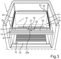
- In 3 is a corresponding representation as in 2 shown.
- the lid 9 is shown in the open position.
- the base plate 17 is linearly backwards in the depth direction and backwards relative to the frame 12 moved backwards.
- the first display area 27 can be viewed from above. It is not covered by the base plate 17 and not by the front strip 18 from above.
- this first display area 27 is not covered by any other element from above. It is thus completely exposed at the top.
- the second display area 26 is covered from above according to the invention. According to the invention, it is covered from above by the front strip 18, in particular completely covered and cannot be looked into according to the invention.
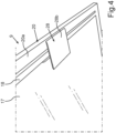
- the cover 9 is shown in a partial representation.
- the perspective view shows a view from below.
- the closed position of the cover 9 is shown here.
- the cover 9 has a plate 28 .
- the plate 28 is oriented in a horizontal plane.
- the plate 28 is formed on the frame 12 .
- it is designed in one piece with the frame 12 .
- the plate 28 is arranged on an underside 20a of the front frame part 20 . It thus extends below the frame 12 and below the cover plate 13. It extends from this front frame part 20 in the depth direction backwards in the direction of the rear frame part 23.
- the plate 28 extends further in the depth direction than the front frame part 20. It is free protruding backwards.
- the plate 28 is preferably arranged centrally on the front frame part 20 viewed in the width direction and is less than half, in particular less than a third, of the length of the front frame part 20 measured in the width direction.
- the indicator bar 25 is on a top 28a ( 3 ), the one in 4 recognizable underside 28b opposite, formed. Provision can be made for the cover plate 13 to be arranged and guided without contact with the plate 28 . It can also be provided that the plate 28 serves as a support for the cover plate 13 and is in contact with the cover plate 13 in this regard. This can take place outside of the display areas 26 and 27 in particular. As a result, the display areas 26 and 27 are not scratched or otherwise impaired.
Landscapes
- Engineering & Computer Science (AREA)
- Chemical & Material Sciences (AREA)
- Combustion & Propulsion (AREA)
- Physics & Mathematics (AREA)
- Mechanical Engineering (AREA)
- Thermal Sciences (AREA)
- General Engineering & Computer Science (AREA)
- Cold Air Circulating Systems And Constructional Details In Refrigerators (AREA)
Applications Claiming Priority (1)
| Application Number | Priority Date | Filing Date | Title |
|---|---|---|---|
| DE102019214596.5A DE102019214596A1 (de) | 2019-09-24 | 2019-09-24 | Lebensmittel-Aufnahmebehälter mit Schale und spezifischer Positionsanzeige eines Deckels dazu, sowie Haushaltskältegerät |
Publications (2)
| Publication Number | Publication Date |
|---|---|
| EP3798550A1 EP3798550A1 (de) | 2021-03-31 |
| EP3798550B1 true EP3798550B1 (de) | 2023-08-23 |
Family
ID=72428219
Family Applications (1)
| Application Number | Title | Priority Date | Filing Date |
|---|---|---|---|
| EP20194984.9A Active EP3798550B1 (de) | 2019-09-24 | 2020-09-08 | Lebensmittel-aufnahmebehälter mit schale und spezifischer positionsanzeige eines deckels dazu, sowie ein haushaltskältegerät |
Country Status (3)
| Country | Link |
|---|---|
| EP (1) | EP3798550B1 (pl) |
| DE (1) | DE102019214596A1 (pl) |
| PL (1) | PL3798550T3 (pl) |
Citations (1)
| Publication number | Priority date | Publication date | Assignee | Title |
|---|---|---|---|---|
| EP2662648B1 (de) * | 2012-05-10 | 2019-05-01 | Miele & Cie. KG | Kühl- oder Klimaschrank |
Family Cites Families (4)
| Publication number | Priority date | Publication date | Assignee | Title |
|---|---|---|---|---|
| DE102012221499A1 (de) * | 2012-11-23 | 2014-05-28 | BSH Bosch und Siemens Hausgeräte GmbH | Haushaltskältegerät mit einem Anzeigemittel für einen Behälterdeckel |
| DE102012221497A1 (de) * | 2012-11-23 | 2014-05-28 | BSH Bosch und Siemens Hausgeräte GmbH | Haushaltskältegerät mit einem Betätigungsmittel für einen Behälterdeckel |
| EP2932171B1 (de) * | 2012-12-11 | 2018-02-21 | BSH Hausgeräte GmbH | Haushaltskältegerät mit einem anzeigemittel für einen behälterdeckel |
| TR201910712T4 (tr) * | 2015-04-21 | 2019-08-21 | Bsh Hausgeraete Gmbh | Beyaz eşya donanımı. |
-
2019
- 2019-09-24 DE DE102019214596.5A patent/DE102019214596A1/de not_active Withdrawn
-
2020
- 2020-09-08 EP EP20194984.9A patent/EP3798550B1/de active Active
- 2020-09-08 PL PL20194984.9T patent/PL3798550T3/pl unknown
Patent Citations (1)
| Publication number | Priority date | Publication date | Assignee | Title |
|---|---|---|---|---|
| EP2662648B1 (de) * | 2012-05-10 | 2019-05-01 | Miele & Cie. KG | Kühl- oder Klimaschrank |
Also Published As
| Publication number | Publication date |
|---|---|
| EP3798550A1 (de) | 2021-03-31 |
| PL3798550T3 (pl) | 2024-02-26 |
| DE102019214596A1 (de) | 2021-03-25 |
Similar Documents
| Publication | Publication Date | Title |
|---|---|---|
| EP3077739B1 (de) | Haushaltskältegerät mit einem bedienelement zum verstellen eines deckels eines frischhaltebehälters, welches in drei verschiedenen stellungen arretierbar ist | |
| EP2923165B1 (de) | Haushaltskältegerät mit einem betätigungsmittel für einen behälterdeckel | |
| EP3077746A1 (de) | Haushaltskältegerät mit einer über einem frischhaltebehälter angeordneten trennwand und einer anzeigeeinheit | |
| DE102014218274A1 (de) | Haushaltskältegerät mit einem mit integrierter Anzeigeeinheit ausgebildetem Bedienelement zum Betätigen eines Deckels eines Frischhaltebehälters | |
| WO2014206807A1 (de) | Haushaltskältegerät mit einem frischhaltebehälter und einem bedienelement, das als push-push-verriegelungsmechanik zum bewegen eines deckels für den frischhaltebehälter ausgebildet ist | |
| EP3168554A1 (de) | Haushaltskältegerät mit einem frischhaltebehälter, dessen frontwand eine aussenwand des geräts ist | |
| WO2015082273A1 (de) | Haushaltskältegerät mit einer anzeigeeinheit zur symbolischen anzeige eines feuchtegehalts in einem frischhaltebehälter und einem damit gekoppelten bedienelement | |
| DE102013225090A1 (de) | Haushaltskältegerät mit einem Frischhaltebehälter in einem Innenraum, der einen mit einem Bedienelement in einer Schublade anheb- und absenkbaren Deckel aufweist | |
| EP3798550A1 (de) | Lebensmittel-aufnahmebehälter mit schale und spezifischer positionsanzeige eines deckels dazu, sowie haushaltskältegerät | |
| EP3798546B1 (de) | Lebensmittel-aufnahmebehälter mit spezifisch geformter klappe einer lüftungseinrichtung, sowie haushaltskältegerät | |
| DE102015206860A1 (de) | Haushaltskältegerät mit entnehmbarer Trennwand in einer Lebensmittelaufnahme-Schale | |
| EP3077745B1 (de) | Haushaltskältegerät mit einer horizontalen trennwand im innenraum | |
| DE102014223518A1 (de) | Haushaltskältegerät mit einer Lebensmittel-Aufnahmeschale in einem Aufnahmeraum, welche eine Frontwand aus Glas aufweist | |
| EP3457055A1 (de) | Türabsteller für ein kältegerät | |
| EP3798549A1 (de) | Lebensmittel-aufnahmebehälter mit schale und spezifischem deckel dazu, sowie haushaltskältegerät | |
| EP4130626B1 (de) | Lebensmittel-aufnahmebehälter mit einer klimatisierungsvorrichtung mit u-förmigen schieber an einer frontleiste, sowie haushaltskältegerät | |
| EP3809079B1 (de) | Lebensmittel-aufnahmebehälter mit einer schwenkbaren klappe an der schale, sowie haushaltskältegerät | |
| EP4086545B1 (de) | Lebensmittel-aufnahmebehälter mit einer klimatisierungsvorrichtung mit spezifischem verstellteil zwischen einer schale und einem aufsatz, sowie haushaltskältegerät | |
| WO2014206811A1 (de) | Haushaltskältegerät mit einem frischhaltebehälter und einem bedienelement und einer bewegungsführungseinrichtung | |
| DE102012221501A1 (de) | Haushaltskältegerät mit einem Betätigungsmittel für einen Behälterdeckel | |
| EP3809069A1 (de) | Lebensmittel-aufnahmebehälter mit in tiefenrichtung verschiebbarem schieber einer lüftungsvorrichtung, sowie haushaltskältegerät | |
| DE102022212297A1 (de) | Haushaltskältegerät mit Lebensmittel-Aufnahmebehälter mit einer Klimatisierungsvorrichtung mit in einem Rahmen fest verbautem Betätigungselement | |
| DE4233135A1 (de) | Kühlgerät, insbesondere Kühl- oder Gefrierschrank | |
| DE202008000759U1 (de) | Kühl- und/oder Gefriergerät | |
| DE102021206173A1 (de) | Speisenaufnahmebehälter, umfassend eine Klimatisierungsvorrichtung mit spezifischer Betriebszustandsanzeige, sowie Haushaltskältegerät |
Legal Events
| Date | Code | Title | Description |
|---|---|---|---|
| PUAI | Public reference made under article 153(3) epc to a published international application that has entered the european phase |
Free format text: ORIGINAL CODE: 0009012 |
|
| STAA | Information on the status of an ep patent application or granted ep patent |
Free format text: STATUS: THE APPLICATION HAS BEEN PUBLISHED |
|
| AK | Designated contracting states |
Kind code of ref document: A1 Designated state(s): AL AT BE BG CH CY CZ DE DK EE ES FI FR GB GR HR HU IE IS IT LI LT LU LV MC MK MT NL NO PL PT RO RS SE SI SK SM TR |
|
| AX | Request for extension of the european patent |
Extension state: BA ME |
|
| STAA | Information on the status of an ep patent application or granted ep patent |
Free format text: STATUS: REQUEST FOR EXAMINATION WAS MADE |
|
| 17P | Request for examination filed |
Effective date: 20210930 |
|
| RBV | Designated contracting states (corrected) |
Designated state(s): AL AT BE BG CH CY CZ DE DK EE ES FI FR GB GR HR HU IE IS IT LI LT LU LV MC MK MT NL NO PL PT RO RS SE SI SK SM TR |
|
| GRAP | Despatch of communication of intention to grant a patent |
Free format text: ORIGINAL CODE: EPIDOSNIGR1 |
|
| STAA | Information on the status of an ep patent application or granted ep patent |
Free format text: STATUS: GRANT OF PATENT IS INTENDED |
|
| INTG | Intention to grant announced |
Effective date: 20230419 |
|
| GRAS | Grant fee paid |
Free format text: ORIGINAL CODE: EPIDOSNIGR3 |
|
| GRAA | (expected) grant |
Free format text: ORIGINAL CODE: 0009210 |
|
| STAA | Information on the status of an ep patent application or granted ep patent |
Free format text: STATUS: THE PATENT HAS BEEN GRANTED |
|
| P01 | Opt-out of the competence of the unified patent court (upc) registered |
Effective date: 20230707 |
|
| AK | Designated contracting states |
Kind code of ref document: B1 Designated state(s): AL AT BE BG CH CY CZ DE DK EE ES FI FR GB GR HR HU IE IS IT LI LT LU LV MC MK MT NL NO PL PT RO RS SE SI SK SM TR |
|
| REG | Reference to a national code |
Ref country code: GB Ref legal event code: FG4D Free format text: NOT ENGLISH |
|
| REG | Reference to a national code |
Ref country code: CH Ref legal event code: EP |
|
| REG | Reference to a national code |
Ref country code: IE Ref legal event code: FG4D Free format text: LANGUAGE OF EP DOCUMENT: GERMAN |
|
| REG | Reference to a national code |
Ref country code: DE Ref legal event code: R096 Ref document number: 502020004824 Country of ref document: DE |
|
| REG | Reference to a national code |
Ref country code: LT Ref legal event code: MG9D |
|
| REG | Reference to a national code |
Ref country code: NL Ref legal event code: MP Effective date: 20230823 |
|
| PG25 | Lapsed in a contracting state [announced via postgrant information from national office to epo] |
Ref country code: GR Free format text: LAPSE BECAUSE OF FAILURE TO SUBMIT A TRANSLATION OF THE DESCRIPTION OR TO PAY THE FEE WITHIN THE PRESCRIBED TIME-LIMIT Effective date: 20231124 |
|
| PG25 | Lapsed in a contracting state [announced via postgrant information from national office to epo] |
Ref country code: IS Free format text: LAPSE BECAUSE OF FAILURE TO SUBMIT A TRANSLATION OF THE DESCRIPTION OR TO PAY THE FEE WITHIN THE PRESCRIBED TIME-LIMIT Effective date: 20231223 |
|
| PG25 | Lapsed in a contracting state [announced via postgrant information from national office to epo] |
Ref country code: SE Free format text: LAPSE BECAUSE OF FAILURE TO SUBMIT A TRANSLATION OF THE DESCRIPTION OR TO PAY THE FEE WITHIN THE PRESCRIBED TIME-LIMIT Effective date: 20230823 Ref country code: RS Free format text: LAPSE BECAUSE OF FAILURE TO SUBMIT A TRANSLATION OF THE DESCRIPTION OR TO PAY THE FEE WITHIN THE PRESCRIBED TIME-LIMIT Effective date: 20230823 Ref country code: PT Free format text: LAPSE BECAUSE OF FAILURE TO SUBMIT A TRANSLATION OF THE DESCRIPTION OR TO PAY THE FEE WITHIN THE PRESCRIBED TIME-LIMIT Effective date: 20231226 Ref country code: NO Free format text: LAPSE BECAUSE OF FAILURE TO SUBMIT A TRANSLATION OF THE DESCRIPTION OR TO PAY THE FEE WITHIN THE PRESCRIBED TIME-LIMIT Effective date: 20231123 Ref country code: NL Free format text: LAPSE BECAUSE OF FAILURE TO SUBMIT A TRANSLATION OF THE DESCRIPTION OR TO PAY THE FEE WITHIN THE PRESCRIBED TIME-LIMIT Effective date: 20230823 Ref country code: LV Free format text: LAPSE BECAUSE OF FAILURE TO SUBMIT A TRANSLATION OF THE DESCRIPTION OR TO PAY THE FEE WITHIN THE PRESCRIBED TIME-LIMIT Effective date: 20230823 Ref country code: LT Free format text: LAPSE BECAUSE OF FAILURE TO SUBMIT A TRANSLATION OF THE DESCRIPTION OR TO PAY THE FEE WITHIN THE PRESCRIBED TIME-LIMIT Effective date: 20230823 Ref country code: IS Free format text: LAPSE BECAUSE OF FAILURE TO SUBMIT A TRANSLATION OF THE DESCRIPTION OR TO PAY THE FEE WITHIN THE PRESCRIBED TIME-LIMIT Effective date: 20231223 Ref country code: HR Free format text: LAPSE BECAUSE OF FAILURE TO SUBMIT A TRANSLATION OF THE DESCRIPTION OR TO PAY THE FEE WITHIN THE PRESCRIBED TIME-LIMIT Effective date: 20230823 Ref country code: GR Free format text: LAPSE BECAUSE OF FAILURE TO SUBMIT A TRANSLATION OF THE DESCRIPTION OR TO PAY THE FEE WITHIN THE PRESCRIBED TIME-LIMIT Effective date: 20231124 Ref country code: FI Free format text: LAPSE BECAUSE OF FAILURE TO SUBMIT A TRANSLATION OF THE DESCRIPTION OR TO PAY THE FEE WITHIN THE PRESCRIBED TIME-LIMIT Effective date: 20230823 |
|
| PG25 | Lapsed in a contracting state [announced via postgrant information from national office to epo] |
Ref country code: ES Free format text: LAPSE BECAUSE OF FAILURE TO SUBMIT A TRANSLATION OF THE DESCRIPTION OR TO PAY THE FEE WITHIN THE PRESCRIBED TIME-LIMIT Effective date: 20230823 |
|
| PG25 | Lapsed in a contracting state [announced via postgrant information from national office to epo] |
Ref country code: SM Free format text: LAPSE BECAUSE OF FAILURE TO SUBMIT A TRANSLATION OF THE DESCRIPTION OR TO PAY THE FEE WITHIN THE PRESCRIBED TIME-LIMIT Effective date: 20230823 Ref country code: RO Free format text: LAPSE BECAUSE OF FAILURE TO SUBMIT A TRANSLATION OF THE DESCRIPTION OR TO PAY THE FEE WITHIN THE PRESCRIBED TIME-LIMIT Effective date: 20230823 Ref country code: ES Free format text: LAPSE BECAUSE OF FAILURE TO SUBMIT A TRANSLATION OF THE DESCRIPTION OR TO PAY THE FEE WITHIN THE PRESCRIBED TIME-LIMIT Effective date: 20230823 Ref country code: EE Free format text: LAPSE BECAUSE OF FAILURE TO SUBMIT A TRANSLATION OF THE DESCRIPTION OR TO PAY THE FEE WITHIN THE PRESCRIBED TIME-LIMIT Effective date: 20230823 Ref country code: DK Free format text: LAPSE BECAUSE OF FAILURE TO SUBMIT A TRANSLATION OF THE DESCRIPTION OR TO PAY THE FEE WITHIN THE PRESCRIBED TIME-LIMIT Effective date: 20230823 Ref country code: CZ Free format text: LAPSE BECAUSE OF FAILURE TO SUBMIT A TRANSLATION OF THE DESCRIPTION OR TO PAY THE FEE WITHIN THE PRESCRIBED TIME-LIMIT Effective date: 20230823 Ref country code: SK Free format text: LAPSE BECAUSE OF FAILURE TO SUBMIT A TRANSLATION OF THE DESCRIPTION OR TO PAY THE FEE WITHIN THE PRESCRIBED TIME-LIMIT Effective date: 20230823 |
|
| REG | Reference to a national code |
Ref country code: CH Ref legal event code: PL |
|
| PG25 | Lapsed in a contracting state [announced via postgrant information from national office to epo] |
Ref country code: LU Free format text: LAPSE BECAUSE OF NON-PAYMENT OF DUE FEES Effective date: 20230908 |
|
| REG | Reference to a national code |
Ref country code: DE Ref legal event code: R097 Ref document number: 502020004824 Country of ref document: DE |
|
| REG | Reference to a national code |
Ref country code: BE Ref legal event code: MM Effective date: 20230930 |
|
| PG25 | Lapsed in a contracting state [announced via postgrant information from national office to epo] |
Ref country code: LU Free format text: LAPSE BECAUSE OF NON-PAYMENT OF DUE FEES Effective date: 20230908 Ref country code: IT Free format text: LAPSE BECAUSE OF FAILURE TO SUBMIT A TRANSLATION OF THE DESCRIPTION OR TO PAY THE FEE WITHIN THE PRESCRIBED TIME-LIMIT Effective date: 20230823 Ref country code: MC Free format text: LAPSE BECAUSE OF FAILURE TO SUBMIT A TRANSLATION OF THE DESCRIPTION OR TO PAY THE FEE WITHIN THE PRESCRIBED TIME-LIMIT Effective date: 20230823 |
|
| PLBE | No opposition filed within time limit |
Free format text: ORIGINAL CODE: 0009261 |
|
| STAA | Information on the status of an ep patent application or granted ep patent |
Free format text: STATUS: NO OPPOSITION FILED WITHIN TIME LIMIT |
|
| REG | Reference to a national code |
Ref country code: IE Ref legal event code: MM4A |
|
| PG25 | Lapsed in a contracting state [announced via postgrant information from national office to epo] |
Ref country code: IE Free format text: LAPSE BECAUSE OF NON-PAYMENT OF DUE FEES Effective date: 20230908 |
|
| PG25 | Lapsed in a contracting state [announced via postgrant information from national office to epo] |
Ref country code: CH Free format text: LAPSE BECAUSE OF NON-PAYMENT OF DUE FEES Effective date: 20230930 |
|
| 26N | No opposition filed |
Effective date: 20240524 |
|
| PG25 | Lapsed in a contracting state [announced via postgrant information from national office to epo] |
Ref country code: IE Free format text: LAPSE BECAUSE OF NON-PAYMENT OF DUE FEES Effective date: 20230908 Ref country code: FR Free format text: LAPSE BECAUSE OF NON-PAYMENT OF DUE FEES Effective date: 20231023 Ref country code: CH Free format text: LAPSE BECAUSE OF NON-PAYMENT OF DUE FEES Effective date: 20230930 Ref country code: SI Free format text: LAPSE BECAUSE OF FAILURE TO SUBMIT A TRANSLATION OF THE DESCRIPTION OR TO PAY THE FEE WITHIN THE PRESCRIBED TIME-LIMIT Effective date: 20230823 |
|
| PG25 | Lapsed in a contracting state [announced via postgrant information from national office to epo] |
Ref country code: BE Free format text: LAPSE BECAUSE OF NON-PAYMENT OF DUE FEES Effective date: 20230930 |
|
| PG25 | Lapsed in a contracting state [announced via postgrant information from national office to epo] |
Ref country code: BG Free format text: LAPSE BECAUSE OF FAILURE TO SUBMIT A TRANSLATION OF THE DESCRIPTION OR TO PAY THE FEE WITHIN THE PRESCRIBED TIME-LIMIT Effective date: 20230823 |
|
| PG25 | Lapsed in a contracting state [announced via postgrant information from national office to epo] |
Ref country code: BG Free format text: LAPSE BECAUSE OF FAILURE TO SUBMIT A TRANSLATION OF THE DESCRIPTION OR TO PAY THE FEE WITHIN THE PRESCRIBED TIME-LIMIT Effective date: 20230823 |
|
| GBPC | Gb: european patent ceased through non-payment of renewal fee |
Effective date: 20240908 |
|
| PG25 | Lapsed in a contracting state [announced via postgrant information from national office to epo] |
Ref country code: GB Free format text: LAPSE BECAUSE OF NON-PAYMENT OF DUE FEES Effective date: 20240908 |
|
| PG25 | Lapsed in a contracting state [announced via postgrant information from national office to epo] |
Ref country code: CY Free format text: LAPSE BECAUSE OF FAILURE TO SUBMIT A TRANSLATION OF THE DESCRIPTION OR TO PAY THE FEE WITHIN THE PRESCRIBED TIME-LIMIT; INVALID AB INITIO Effective date: 20200908 |
|
| PG25 | Lapsed in a contracting state [announced via postgrant information from national office to epo] |
Ref country code: HU Free format text: LAPSE BECAUSE OF FAILURE TO SUBMIT A TRANSLATION OF THE DESCRIPTION OR TO PAY THE FEE WITHIN THE PRESCRIBED TIME-LIMIT; INVALID AB INITIO Effective date: 20200908 |
|
| PGFP | Annual fee paid to national office [announced via postgrant information from national office to epo] |
Ref country code: DE Payment date: 20250930 Year of fee payment: 6 |
|
| PGFP | Annual fee paid to national office [announced via postgrant information from national office to epo] |
Ref country code: PL Payment date: 20250828 Year of fee payment: 6 Ref country code: TR Payment date: 20250903 Year of fee payment: 6 |
|
| PGFP | Annual fee paid to national office [announced via postgrant information from national office to epo] |
Ref country code: AT Payment date: 20251020 Year of fee payment: 5 |