EP3798390B2 - Faltanlage - Google Patents
Faltanlage Download PDFInfo
- Publication number
- EP3798390B2 EP3798390B2 EP20197856.6A EP20197856A EP3798390B2 EP 3798390 B2 EP3798390 B2 EP 3798390B2 EP 20197856 A EP20197856 A EP 20197856A EP 3798390 B2 EP3798390 B2 EP 3798390B2
- Authority
- EP
- European Patent Office
- Prior art keywords
- folding
- profile
- locking
- reinforcing
- pin
- Prior art date
- Legal status (The legal status is an assumption and is not a legal conclusion. Google has not performed a legal analysis and makes no representation as to the accuracy of the status listed.)
- Active
Links
Images
Classifications
-
- E—FIXED CONSTRUCTIONS
- E05—LOCKS; KEYS; WINDOW OR DOOR FITTINGS; SAFES
- E05C—BOLTS OR FASTENING DEVICES FOR WINGS, SPECIALLY FOR DOORS OR WINDOWS
- E05C9/00—Arrangements of simultaneously actuated bolts or other securing devices at well-separated positions on the same wing
- E05C9/04—Arrangements of simultaneously actuated bolts or other securing devices at well-separated positions on the same wing with two sliding bars moved in opposite directions when fastening or unfastening
-
- E—FIXED CONSTRUCTIONS
- E05—LOCKS; KEYS; WINDOW OR DOOR FITTINGS; SAFES
- E05B—LOCKS; ACCESSORIES THEREFOR; HANDCUFFS
- E05B15/00—Other details of locks; Parts for engagement by bolts of fastening devices
- E05B15/10—Bolts of locks or night latches
- E05B15/108—Bolts with multiple head
-
- E—FIXED CONSTRUCTIONS
- E05—LOCKS; KEYS; WINDOW OR DOOR FITTINGS; SAFES
- E05B—LOCKS; ACCESSORIES THEREFOR; HANDCUFFS
- E05B65/00—Locks or fastenings for special use
- E05B65/0085—Locks or fastenings for special use for folding wings, e.g. bi-fold wings
-
- E—FIXED CONSTRUCTIONS
- E05—LOCKS; KEYS; WINDOW OR DOOR FITTINGS; SAFES
- E05C—BOLTS OR FASTENING DEVICES FOR WINGS, SPECIALLY FOR DOORS OR WINDOWS
- E05C9/00—Arrangements of simultaneously actuated bolts or other securing devices at well-separated positions on the same wing
- E05C9/18—Details of fastening means or of fixed retaining means for the ends of bars
- E05C9/1825—Fastening means
- E05C9/1833—Fastening means performing sliding movements
- E05C9/185—Fastening means performing sliding movements parallel with actuating bar
-
- E—FIXED CONSTRUCTIONS
- E05—LOCKS; KEYS; WINDOW OR DOOR FITTINGS; SAFES
- E05C—BOLTS OR FASTENING DEVICES FOR WINGS, SPECIALLY FOR DOORS OR WINDOWS
- E05C9/00—Arrangements of simultaneously actuated bolts or other securing devices at well-separated positions on the same wing
- E05C9/20—Coupling means for sliding bars, rods, or cables
-
- E—FIXED CONSTRUCTIONS
- E05—LOCKS; KEYS; WINDOW OR DOOR FITTINGS; SAFES
- E05C—BOLTS OR FASTENING DEVICES FOR WINGS, SPECIALLY FOR DOORS OR WINDOWS
- E05C9/00—Arrangements of simultaneously actuated bolts or other securing devices at well-separated positions on the same wing
- E05C9/22—Guides for sliding bars, rods or cables
-
- E—FIXED CONSTRUCTIONS
- E06—DOORS, WINDOWS, SHUTTERS, OR ROLLER BLINDS IN GENERAL; LADDERS
- E06B—FIXED OR MOVABLE CLOSURES FOR OPENINGS IN BUILDINGS, VEHICLES, FENCES OR LIKE ENCLOSURES IN GENERAL, e.g. DOORS, WINDOWS, BLINDS, GATES
- E06B3/00—Window sashes, door leaves, or like elements for closing wall or like openings; Layout of fixed or moving closures, e.g. windows in wall or like openings; Features of rigidly-mounted outer frames relating to the mounting of wing frames
- E06B3/32—Arrangements of wings characterised by the manner of movement; Arrangements of movable wings in openings; Features of wings or frames relating solely to the manner of movement of the wing
- E06B3/48—Wings connected at their edges, e.g. foldable wings
- E06B3/481—Wings foldable in a zig-zag manner or bi-fold wings
Definitions
- the invention relates to a folding system with folding wings guided in guide rails at the top and bottom according to the preamble of claim 1.
- wings of the folding system In order to open the wings of the folding system, they can be moved in the guide rails and/or pivoted out of them. In the closed position, a locking mechanism is required.
- a locking fitting is accommodated in the frame profile of at least one of the folding wings.
- locking pins can usually be moved into the guide rail at the top and bottom, or out of it, when the system is to be opened again.
- the EP 2 275 632 B1 A locking mechanism has already been proposed in which the adjacent frame profile of the wing adjoining the folding wing to be locked also has a latch that can be operated simultaneously via a driver on the locking fitting. Although this design offers increased protection against burglary, it is relatively complicated.
- the US 2017/0 058 578 A1 reveals a double bolt lock for a folding door. Using a handle, bolts can be moved up or down to engage with rails.
- the US 2019/0 119 964 A1 discloses a locking system for doors or windows. Using a handle, bolts can be moved up or down to engage with grooves.
- the invention is therefore based on the object of creating a folding system with a secure locking mechanism that is structurally simple and solid. This object is achieved by a folding system with the features of claim 1.
- the two pins can be connected in parallel but firmly in terms of their movement, so that the reinforcement pin is arranged so that it can move with the locking pin. There is no need for coupling across the movable space between two sashes.
- the locking of both pins can still only be carried out using a locking gear.
- the additional reinforcement pin means that the locking forces are applied at several points (locking pin and reinforcement pin), which at least halves the load or force on the individual pin. In the event of attempted break-ins or impending wind loads, the force introduced into the guide rail is better distributed and reduces the risk of the guide rail or pins bending.
- the improved locking effect also extends to the folding sash adjacent to the lock.
- the locking mechanism according to the invention can also be used on the wall side or on folding sashes that are not firmly connected to an adjacent sash, in particular not via hinges.
- a supplementary reinforcement profile of the frame profile which increases the stability of the folding sash against bending. With the appropriate design, deflection of the folding sash under wind load can be reduced to such an extent that there is no longer any risk of locking and reinforcement pins jumping out of the guide rails.
- a supplementary reinforcement profile can also be easily retrofitted, particularly if it is detachably attached to the existing frame profile piece, or only provided when required. However, it is also possible to form the reinforcement profile as one piece with the profile piece that accommodates the locking pins.
- the frame profile has a vertical, sword-like projection that counteracts deflections.
- the projection preferably has a strip-like or sword-like shape with a height that preferably takes up a predominant part of the height of the vertical frame profile.
- the width of the projection in contrast, is rather small, and its depth, i.e. its extension perpendicular to the folding sash plane, is preferably greater than its width.
- the projection can be formed in one piece with the frame profile or connected to it. If this projection is provided on the reinforcement profile, the number of components required for different embodiments can still be kept small, since the required stability can be adjusted on a case-by-case basis by choosing a suitable reinforcement profile, with or without a projection.
- the reinforcing pin can be connected to the locking pin via an adapter piece.
- the adapter piece has a mounting recess that allows access with tools to create the connection.
- the adapter piece can be essentially C- or U-shaped for this purpose.
- the adapter piece can be used structurally to guide the movement of the reinforcement pin, for which it is advantageous that the adapter piece has a guide surface that can be moved vertically against a guide counter surface of the reinforcement profile.
- a corresponding design is also possible on the opposite side in the profile piece.
- the C- or U-shaped adapter piece preferably has at least two essentially horizontal legs that are connected by at least one essentially vertical leg. Coupling areas are formed in the essentially horizontal legs, on which force transmission elements, in particular locking rods, engage for transmitting force to the pins. Between the essentially horizontal legs there is a mounting recess, the free height of which in the vertical direction is preferably greater than the height in the vertical direction of the essentially horizontal legs, in particular even than the sum of the heights of the essentially vertical legs. This structure facilitates the assembly and maintenance of the folding system. Specifically, the free height of the mounting recess should correspond at least to the length of the connecting elements to be used, e.g. screws including the screw heads that pass through the coupling areas.
- the coupling areas of the adapter piece are at least partially designed as recesses or even partially as through-holes and can extend from below/above preferably parallel through the adapter piece.
- At least one of the two recesses is designed as a through-hole in particular through a first of the essentially horizontal legs.
- the other recess in this leg can be a blind hole.
- each of the two recesses can accommodate a locking rod.
- One of the locking rods is connected to the locking pin, the other of the locking rods to the reinforcing pin.
- a third recess is preferably designed as a through-hole through a second of the essentially horizontal legs. When the folding system is assembled, this hole can accommodate a push rod for introducing force. It is particularly preferred that an adapter piece designed in this way is arranged on both sides of the locking gear.
- the transfer of locking forces to the guide rails is particularly safe but gentle on the material if the locking pins and reinforcing pins are spaced apart from each other in terms of their contact points with the guide rail.
- the distance can be approximately the same as the diameter of the pins. It is advantageous if the distance is at least as large as the load-bearing penetration depth of the pins into the guide rail.
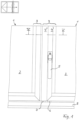
- Fig. 1 the lower area of two interconnected folding wings 1 is shown in the closed functional position of the locking mechanism. Above this, at the top left, there is a small pictogram-like representation of an example folding system to illustrate the function.
- the folding wings 1 shown each have glass panes 2 which are held in frame profiles 3, 4.
- the folding wing 1 on the right in the illustration has a locking mechanism which can be operated using a handle 5. This allows a locking pin 6 and a reinforcing pin 7 to be moved into the guide rail 8, which prevents the wings from pivoting.
- the locking pin 6 is guided in a profile piece 4' of the frame profile 4, while the reinforcing pin 7 is accommodated in a reinforcing profile 4" of the frame profile 4.
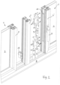
- the Fig. 2 to 5 illustrate the function and the individual components of the construction according to the invention.
- the frame profiles 3, 4 and the guide rail 8 are shown transparently (dash-dotted) without the handle, so that an internal locking gear 9 with adjoining components is visible.
- the locking gear 9 acts via push rods 10 and adjoining adapter pieces 11 on locking bars 12 connected to them, at the ends of which there are locking pins 6 and reinforcing pins 7.
- the upper locking bars 12 also have pins 6, 7, which, however, cannot be seen here because of the cut-off illustration above.
- the locking bars 12 can also form the pins 6, 7 themselves with their ends and/or merge into them in one piece.
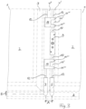
- FIG. 2 and 3 the locking mechanism is shown in its closed functional position, with the pins 6,7 entering the guide rail 8 and thus locking the folding wings.
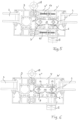
- Fig. 4 shows the locking mechanism in its open position.
- the handle 5 (not shown there) was swivelled upwards by 180° and the adapter pieces 11 with the connected locking rods 12 and the pins 6,7 were moved towards the locking mechanism 9 via the gear 9.
- the pins 6,7 are now outside the guide rail 8 and release the folding wings 1 for opening.
- the pins 6,7 are spaced apart from one another by a distance A.
- this is measured between the central longitudinal axes of the pins 6,7, since these are round and therefore only touch linearly in the rail 8.
- the distance A should at least correspond to the load-bearing penetration depth E of the pins 6,7 in the rail 8, but should preferably be larger, particularly preferably even twice as large.
- both parts 4', 4" have a recess 16 (see Fig. 2 ), through which the adapter pieces 11 penetrate.
- the recesses 16 are to be designed to be large enough to allow the up and down movement of the adapter pieces 11 when locking and unlocking.
- the adapter pieces 11 have mounting recesses 11', which make it possible to attach the adjacent push rods 10 and locking rods 12 to the adapter pieces 11 using appropriate tools.
- the adapter pieces 11 have guide surfaces 11" on their side facing the reinforcement profile 4", which rest against a guide counter surface 21 of the reinforcement profile 4", whereby the up and down movement of the adapter pieces 11 is stabilized and guided.
- corresponding guide surfaces 11"' are also provided on the opposite side in an advantageous manner to increase stability, which rest against a guide counter surface 21' of the profile piece 4'.
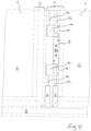
- FIG. 1 to 5 show an embodiment in which the frame profile 4 is composed of two profile parts detachably connected by means of screw connections 17, namely the profile piece 4' and the reinforcement profile 4"
- Fig. 6 an alternative embodiment with a one-piece design of the frame profile 4.
- the frame profile 4 is connected to the frame profile 3 of the adjacent folding wing 1 via hinge fittings 18, so that the two folding wings 1 can be pivoted against each other in the fully assembled state of the folding system and with the locking mechanism in the open position, but remain connected.
- the structural design of the folding system according to the invention and in particular its locking mechanism is simple, solid, low-maintenance and safe.
Landscapes
- Engineering & Computer Science (AREA)
- Mechanical Engineering (AREA)
- Civil Engineering (AREA)
- Structural Engineering (AREA)
- Extensible Doors And Revolving Doors (AREA)
- Support Devices For Sliding Doors (AREA)
- Roof Covering Using Slabs Or Stiff Sheets (AREA)
Description
- Die Erfindung betrifft eine Faltanlage mit oben- und untenseitig in Führungsschienen geführten Faltflügeln nach dem Oberbegriff des Anspruchs 1. Dabei können zum Öffnen die Flügel der Faltanlage in den Führungsschienen verschoben und/oder aus diesen heraus verschwenkt werden. In geschlossener Position bedarf es einer Verriegelung. Dazu ist ein Verriegelungsbeschlag im Rahmenprofil von zumindest einem der Faltflügel aufgenommen. Über ein Verriegelungsgetriebe können Verriegelungszapfen zumeist oben und unten in die Führungsschiene hineinbewegt werden, bzw. aus dieser hinaus, wenn die Anlage wieder geöffnet werden soll.
- Um einer verbesserten Absicherung Rechnung zu tragen, wird in der
EP 2 275 632 B1 bereits ein Verriegelungsmechanismus vorgeschlagen, bei dem das benachbarte Rahmenprofil des sich an den zu verriegelnden Faltflügel anschließenden Flügels ebenfalls einen Riegel aufweist, der über Mitnehmer am Verriegelungsbeschlag gleichzeitig betätigbar ist. Diese Konstruktion bietet zwar einen erhöhten Einbruchschutz, ist aber verhältnismäßig kompliziert. - Die
US 2017/0 058 578 A1 offenbart ein Doppelbolzenschloss für eine Falttür. Mittels eines Griffs lassen sich Bolzen nach oben bzw. unten bewegen, um sie in Eingriff mit Schienen zu bringen. - Die
US 2019/0 119 964 A1 offenbart ein Verriegelungssystem für Türen oder Fenster. Mittels eines Griffs lassen sich Bolzen nach oben bzw. unten bewegen, um sie in Eingriff mit Nuten zu bringen. - Der Erfindung liegt daher die Aufgabe zugrunde, eine Faltanlage mit einer sicheren Verriegelung zu schaffen, die konstruktiv einfach und solide ist. Diese Aufgabe wird durch eine Faltanlage mit den Merkmalen des Anspruchs 1 gelöst.
- Durch das Vorsehen mindestens eines Verriegelungszapfens in der Funktion eines Verstärkungszapfens im Rahmenprofil desselben Faltflügels, in dem sich auch der Verriegelungszapfen befindet, können die beiden Zapfen hinsichtlich ihrer Bewegung parallel aber fest verbunden werden, so dass der Verstärkungszapfen mit dem Verriegelungszapfen mitbewegbar angeordnet ist. Es bedarf keiner Koppelung über den beweglichen Zwischenraum zweier Flügel hinweg. Die Verriegelung beider Zapfen kann weiterhin nur über ein Verriegelungsgetriebe erfolgen. Durch den zusätzlichen Verstärkungszapfen setzen die Verriegelungskräfte jedoch an mehreren Punkten an (Verriegelungszapfen und Verstärkungszapfen), dadurch wird die Belastung bzw. Kraft auf den einzelnen Zapfen zumindest halbiert. Bei Einbruchversuchen oder anstehenden Windlasten verteilt sich die Krafteinleitung in die Führungsschiene besser und verringert die Gefahr, dass sich die Führungsschiene oder die Zapfen verbiegen. Wenn benachbarte Faltflügel über Scharniere verbunden sind, erstreckt sich die verbesserte Verriegelungswirkung auch auf den zur Verriegelung benachbarten Faltflügel. Die erfindungsgemäße Verriegelung kann jedoch ebenfalls wandseitig oder bei Faltflügeln zum Einsatz kommen, die mit einem benachbarten Flügel nicht fest, insbesondere nicht über Scharniere verbunden sind.
- Neben der Sicherung gegen Einbrüche ist insbesondere ein sicheres Verschließen von Faltanlagen bei hohen Windlasten vorteilhaft. Dazu erweist es sich als positiv, den Verstärkungszapfen in einem ergänzenden Verstärkungsprofil des Rahmenprofils aufzunehmen, wodurch die Stabilität des Faltflügels gegen Verbiegen erhöht wird. Bei entsprechender Auslegung kann eine Durchbiegung der Faltflügel unter Windlast soweit herabgesetzt werden, dass keine Gefahr mehr besteht, dass Verriegelungs- und Verstärkungszapfen aus den Führungsschienen herausspringen. Auch lässt sich ein ergänzendes Verstärkungsprofil, insbesondere wenn dieses lösbar am bisherigen Rahmenprofilstück befestigt ist, problemlos nachrüsten oder nur im Bedarfsfall vorsehen. Es ist jedoch auch möglich, das Verstärkungsprofil einstückig mit dem die Verriegelungszapfen aufnehmenden Profilstück auszubilden.
- Eine Stabilitätsverbesserung lässt sich auch erreichen, indem das Rahmenprofil einen senkrecht verlaufenden, schwertartigen Vorsprung aufweist, der Durchbiegungen entgegenwirkt. Der Vorsprung hat bevorzugt eine leistenartige bzw. schwertartige Form mit einer Höhe, die vorzugsweise einen überwiegenden Teil der Höhe des senkrechten Rahmenprofils einnimmt. Die Breite des Vorsprungs ist demgegenüber eher gering, und seine Tiefe, d.h. seine Erstreckung senkrecht zur Faltflügelebene ist bevorzugt größer als seine Breite. Der Vorsprung kann einstückig mit dem Rahmenprofil ausgebildet oder mit diesem verbunden sein. Wenn dieser Vorsprung am Verstärkungsprofil vorgesehen wird, kann die Anzahl der benötigen Komponenten für verschiedene Ausführungsformen dennoch klein gehalten werden, da die erforderliche Stabilität fallweise durch die Wahl eines geeigneten Verstärkungsprofils, mit oder ohne Vorsprung eingestellt werden kann.
- Auf konstruktiv einfache Weise, ohne die Ausgestaltung des Verriegelungsgetriebes verändern zu müssen, kann der Verstärkungszapfen über ein Adapterstück mit dem Verriegelungszapfen verbunden werden. Zur fallweise auch nachträglichen Montage kann es vorteilhaft sein, wenn das Adapterstück dazu eine Montageausnehmung aufweist, die den Zugriff durch Werkzeug zur Herstellung der Verbindung ermöglicht. Das Adapterstück kann dazu im Wesentlichen C- bzw. U-förmig ausgebildet sein.
- Darüber hinaus kann das Adapterstück konstruktiv zur Führung der Bewegung des Verstärkungszapfens genutzt werden, wozu es von Vorteil ist, dass das Adapterstück eine Führungsfläche aufweist, die an einer Führungsgegenfläche des Verstärkungsprofils senkrecht verschiebbar anliegt. Eine entsprechende Ausgestaltung ist auch gegenüberliegend im Profilstück möglich.
- Das C- bzw. U-förmige Adapterstück hat vorzugsweise zumindest zwei im Wesentlichen waagerechte Schenkel, die durch zumindest einen im Wesentlichen senkrechten Schenkel verbunden sind. In den im Wesentlichen waagerechten Schenkeln sind Koppelbereiche ausgebildet, an denen Kraftübertragungselemente, insbesondere Riegelstangen zur Kraftübertragung auf die Zapfen angreifen. Zwischen den im Wesentlichen horizontalen Schenkeln befindet sich eine Montageausnehmung, deren freie Höhe in vertikaler Richtung vorzugsweise größer als die Höhe in vertikaler Richtung der im Wesentlichen horizontalen Schenkel ist, insbesondere sogar als die Summe der Höhen der im Wesentlichen vertikalen Schenkel. Dieser Aufbau erleichtert die Montage und Wartung der Faltanlage. Konkret sollte die freie Höhe der Montageausnehmung mindestens der Länge zu verwendender Verbindungselemente entsprechen, z.B. von Schrauben inklusive der Schraubenköpfe, die die Koppelbereiche durchgreifen.
- Die Koppelbereiche des Adapterstücks sind zumindest teilweise als Ausnehmungen bzw. teilweise sogar als Durchgangsbohrungen ausgebildet und können sich von unten/oben vorzugsweise parallel durch das Adapterstück hindurcherstrecken. Zumindest eine der beiden Ausnehmungen ist insbesondere durch einen ersten der im Wesentlichen waagerechten Schenkel als Durchgangsbohrung ausgebildet. Die andere Ausnehmung in diesem Schenkel kann eine Sacklochbohrung sein. Im montierten Zustand der Faltanlage kann jede der beiden Ausnehmungen eine Riegelstange aufnehmen. Eine der Riegelstangen ist dabei mit dem Verriegelungszapfen, die andere der Riegelstangen mit dem Verstärkungszapfen verbunden. Eine dritte Ausnehmung ist bevorzugt als Durchgangsbohrung durch einen zweiten der im Wesentlichen waagerechten Schenkel ausgebildet. Im montierten Zustand der Faltanlage kann diese Bohrung eine Schubstange zur Einleitung von Kraft aufnehmen. Besonders bevorzugt ist am Verriegelungsgetriebe beidseitig je ein derart ausgebildetes Adapterstück angeordnet.
- Die Übertragung der Verriegelungskräfte auf die Führungsschienen erfolgt besonders sicher aber materialschonend, wenn Verriegelungszapfen und Verstärkungszapfen hinsichtlich ihrer Berührpunkte mit der Führungsschiene voneinander beanstandet angeordnet sind. Der Abstand kann etwa dem Durchmesser der Zapfen entsprechen. Vorteilhaft ist es, wenn der Abstand zumindest so groß ist, wie die tragende Eindringtiefe der Zapfen in die Führungsschiene.
- Weitere Vorteile und Einzelheiten ergeben sich aus den Unteransprüchen und in den Zeichnungen dargestellten Ausführungsbeispielen der Erfindung, die im Folgenden beschrieben werden; es zeigen:
- Fig. 1
- den Verbindungsbereich zweier Faltflügel in verriegelter Position in Frontalansicht,
- Fig. 2
- den Gegenstand aus
Fig. 1 in perspektivischer Ansicht und Sprengdarstellung mit teils voneinander beabstandeten Komponenten, - Fig. 3
- den Gegenstand aus
Fig. 1 unter Sichtbarmachung der Verriegelungskomponenten, - Fig. 4
- den Gegenstand aus
Fig. 3 in entriegelter Position, - Fig. 5
- einen Schnitt in Richtung V-V durch den Gegenstand aus
Fig. 1 und - Fig. 6
- eine alternative Ausführungsform in einer Darstellung gemäß
Fig. 5 . - In
Fig. 1 ist der untere Bereich zweier miteinander verbundener Faltflügel 1 in geschlossener Funktionsstellung der Verriegelung dargestellt. Darüber befindet sich oben links eine kleine piktogrammartige Darstellung einer beispielhaften Faltanlage zur Funktionsveranschaulichung. Die dargestellten Faltflügel 1 haben jeweils Glasscheiben 2, die in Rahmenprofilen 3,4 gehalten sind. Der in der Darstellung rechte Faltflügel 1 verfügt dabei über eine Verriegelung, die über einen Griff 5 betätigbar ist. Damit lassen sich ein Verriegelungszapfen 6 und ein Verstärkungszapfen 7 in die Führungsschiene 8 hineinbewegen, wodurch ein Verschwenken der Flügel verhindert wird. Der Verriegelungszapfen 6 ist in einem Profilstück 4' des Rahmenprofils 4 geführt, während der Verstärkungszapfen 7 in einem Verstärkungsprofil 4" des Rahmenprofils 4 aufgenommen ist. - Die
Fig. 2 bis 5 veranschaulichen die Funktion und die Einzelkomponenten der erfindungsgemäßen Konstruktion. So sind in denFig. 3 und4 unter Weglassung des Griffs die Rahmenprofile 3,4 und die Führungsschiene 8 transparent (strichpunktiert) dargestellt, so dass der Blick auf ein innenliegendes Verriegelungsgetriebe 9 mit sich daran anschließenden Bauteilen freigegeben ist. Das Verriegelungsgetriebe 9 wirkt über Schubstangen 10 und sich daran anschließende Adapterstücke 11 auf mit diesen verbundene Riegelstangen 12, an deren Enden sich Verriegelungszapfen 6 und Verstärkungszapfen 7 befinden. Auch die oberen Riegelstangen 12 tragen bei dieser Ausführungsform Zapfen 6,7, die jedoch wegen der oben abgeschnittenen Darstellung hier nicht zu sehen sind. Selbstverständlich können die Riegelstangen 12 mit ihren Enden auch selbst die Zapfen 6,7 ausbilden und/oder auch einstückig in diese übergehen. - In den
Fig. 2 und3 ist die Verriegelung in ihrer geschlossenen Funktionsstellung gezeigt, wobei die Zapfen 6,7 in die Führungsschiene 8 eintauchen und die Faltflügel so verriegeln.Fig. 4 hingegen zeigt die Verriegelung in ihrer geöffneten Position. Dazu wurden der dort nicht dargestellte Griff 5 um 180° nach oben verschwenkt und so über das Getriebe 9 die Adapterstücke 11 mit den angeschlossenen Riegelstangen 12 und den Zapfen 6,7 zum Verriegelungsgetriebe 9 hin verschoben. Die Zapfen 6,7 befinden sich nun außerhalb der Führungsschiene 8 und geben die Faltflügel 1 zur Öffnung frei. Um die Verriegelungskräfte in der Führungsschiene 8 zu verteilen, sind die Zapfen 6,7 um einen Abstand A voneinander beabstandet. Dieser bemisst sich bei der dargestellten Ausführungsform zwischen den Mittellängsachsen der Zapfen 6,7, da diese rund sind und in der Schiene 8 somit nur linienförmig berührend anliegen. Der Abstand A sollte zumindest der tragenden Eindringtiefe E der Zapfen 6,7 in der Schiene 8 entsprechen, bevorzugt aber größer, besonders bevorzugt sogar doppelt so groß sein. - Weitere Details der Konstruktion sind den
Fig. 2 und5 sowie der inFig. 6 dargestellten Variante zu entnehmen. In zusammengebautem Zustand ist das Verriegelungsgetriebe 9 mit den Schubstangen 10 im Profilstück 4' des Rahmenprofils 4 angeordnet, während sich die Verstärkungszapfen 7 mit einem entsprechenden Teil der Adapterstücke 11 im Verstärkungsprofil 4" befinden. Im Übergang zwischen dem Profilstück 4' und dem Verstärkungsprofil 4" haben beide Teile 4',4" eine Ausnehmung 16 (sieheFig. 2 ), durch die die Adapterstücke 11 hindurchtauchen. Die Ausnehmungen 16 sind so groß auszubilden, dass sie die Auf- und Abbewegung der Adapterstücke 11 bei einem Ver- und Entriegeln zulassen. Die Adapterstücke 11 haben Montageausnehmungen 11', die es ermöglichen, an den Adapterstücken 11 mit entsprechendem Werkzeug die angrenzenden Schubstangen 10 und Riegelstangen 12 zu befestigen. Die Adapterstücke 11 haben auf ihrer dem Verstärkungsprofil 4" zugewandten Seite Führungsflächen 11", die an einer Führungsgegenfläche 21 des Verstärkungsprofils 4" anliegen, wodurch die Auf- und Abbewegung der Adapterstücke 11 stabilisiert und geführt ist. Bei der dargestellten Ausführungsform sind in vorteilhafter Weise stabilitätserhöhend entsprechende Führungsflächen 11"' auch auf der gegenüberliegenden Seite vorgesehen, die an einer Führungsgegenfläche 21' des Profilstücks 4' anliegen. - Während die
Fig. 1 bis 5 eine Ausführungsform zeigen, bei der sich das Rahmenprofil 4 aus zwei mittels Schraubverbindungen 17 lösbar verbundenen Profilteilen, nämlich dem Profilstück 4' und dem Verstärkungsprofil 4" zusammensetzt, zeigtFig. 6 eine alternative Ausführungsform mit einer einstückigen Ausführung des Rahmenprofils 4. In beiden Fällen jedoch ist das Rahmenprofil 4 über Scharnierbeschläge 18 mit dem Rahmenprofil 3 des benachbarten Faltflügels 1 verbunden, so dass die beiden Faltflügel 1 im fertig montierten Zustand der Faltanlage und bei geöffneter Position der Verriegelung gegeneinander verschwenkbar sind, jedoch verbunden bleiben. - Die konstruktive Gestaltung der erfindungsgemäßen Faltanlage und insbesondere ihrer Verriegelung ist einfach, solide, wartungsarm und sicher.
Claims (10)
- Faltanlage, insbesondere Glasfaltanlage, mit zumindest zwei Faltflügeln (1), die in einer Führung mit mindestens einer untenseitigen und einer obenseitigen Führungsschiene (8) beweglich gelagert sind, wobei zumindest ein Faltflügel (1) ein sich senkrecht erstreckendes Rahmenprofil (4) aufweist, das einen Verriegelungsbeschlag mit zumindest einem senkrecht verschiebbar gelagerten Verriegelungszapfen (6) aufnimmt, der mittels eines Verriegelungsgetriebes (9) unten und/oder oben in die Führungsschiene (8) hinein- und herausbewegbar angeordnet ist, dadurch gekennzeichnet, dass der Verriegelungszapfen (6) mit einem parallel im Rahmenprofil (4) desselben Faltflügels (1) angeordneten weiteren Verriegelungszapfen in der Funktion eines Verstärkungszapfens (7) fest verbunden ist, der parallel zum Verriegelungszapfen (6) über das Verriegelungsgetriebe (9) mitbewegt wird.
- Faltanlage nach Anspruch 1, dadurch gekennzeichnet, dass das Rahmenprofil (4) ein ergänzendes Verstärkungsprofil (4") aufweist, das den Verstärkungszapfen (7) aufnimmt.
- Faltanlage nach Anspruch 2, dadurch gekennzeichnet, dass das Verstärkungsprofil (4") lösbar an einem den Verriegelungszapfen (6) aufnehmenden Profilstück (4') befestigt ist.
- Faltanlage nach Anspruch 2, dadurch gekennzeichnet, dass das Verstärkungsprofil (4") einstückig mit einem den Verriegelungszapfen (6) aufnehmenden Profilstück (4') ausgebildet ist.
- Faltanlage nach einem der vorhergehenden Ansprüche, dadurch gekennzeichnet, dass der Verriegelungszapfen (6) über ein Adapterstück (11) mit dem Verstärkungszapfen (7) verbunden ist.
- Faltanlage nach Anspruch 5, dadurch gekennzeichnet, dass das Adapterstück (11) wenigstens eine Montageausnehmung (11') aufweist.
- Faltanlage nach Anspruch 5 oder 6, dadurch gekennzeichnet, dass das Adapterstück (11) zumindest eine Führungsfläche (11") aufweist, die an einer Führungsgegenfläche (21) des Verstärkungsprofils (4") anliegt.
- Faltanlage nach einem der vorhergehenden Ansprüche, dadurch gekennzeichnet, dass Verriegelungszapfen (6) und Verstärkungszapfen (7) voneinander beabstandet angeordnet sind.
- Faltanlage nach einem der vorhergehenden Ansprüche, dadurch gekennzeichnet, dass das Rahmenprofil (4) zumindest einen senkrecht verlaufenden, schwertartigen Vorsprung aufweist.
- Faltanlage nach Anspruch 2 und Anspruch 9, dadurch gekennzeichnet, dass das Verstärkungsprofil (4") den schwertartigen Vorsprung aufweist.
Applications Claiming Priority (1)
| Application Number | Priority Date | Filing Date | Title |
|---|---|---|---|
| DE102019125988.6A DE102019125988A1 (de) | 2019-09-26 | 2019-09-26 | Faltanlage |
Publications (3)
| Publication Number | Publication Date |
|---|---|
| EP3798390A1 EP3798390A1 (de) | 2021-03-31 |
| EP3798390B1 EP3798390B1 (de) | 2022-03-23 |
| EP3798390B2 true EP3798390B2 (de) | 2024-12-25 |
Family
ID=72644041
Family Applications (1)
| Application Number | Title | Priority Date | Filing Date |
|---|---|---|---|
| EP20197856.6A Active EP3798390B2 (de) | 2019-09-26 | 2020-09-23 | Faltanlage |
Country Status (4)
| Country | Link |
|---|---|
| US (1) | US20210095503A1 (de) |
| EP (1) | EP3798390B2 (de) |
| DE (1) | DE102019125988A1 (de) |
| DK (1) | DK3798390T4 (de) |
Families Citing this family (4)
| Publication number | Priority date | Publication date | Assignee | Title |
|---|---|---|---|---|
| WO2018044361A1 (en) | 2016-08-30 | 2018-03-08 | Sargent Manufacturing Company | Mortise lock with multi-point latch system |
| US11208832B2 (en) * | 2016-08-30 | 2021-12-28 | Sargent Manufacturing Company | Mortise lock with multi-point latch system |
| DE102023102027A1 (de) * | 2023-01-27 | 2024-08-01 | Solarlux Gmbh | Schiebeflügelsystem mit spezieller Verriegelung |
| US20250304235A1 (en) * | 2024-03-28 | 2025-10-02 | The Boeing Company | Door Assembly with an Engagement Assembly |
Citations (6)
| Publication number | Priority date | Publication date | Assignee | Title |
|---|---|---|---|---|
| DE3526288C2 (de) † | 1985-07-23 | 1990-07-05 | Hans-Joachim 5000 Koeln De Solbach | |
| DE10100651A1 (de) † | 2001-01-09 | 2002-07-11 | Melchert Beschlaege | Verschluss |
| FR2920807A1 (fr) † | 2007-09-11 | 2009-03-13 | Gaston Hervouet | Dispositif de fermeture a plusieurs points renforcant la securite des ouvrants dans l'habitat |
| DE102010032145A1 (de) † | 2010-07-24 | 2012-01-26 | Novoferm Gmbh | Torverriegelungsvorrichtung sowie Überkopftor umfassend eine Torverriegelungsvorrichtung |
| US20170058578A1 (en) † | 2015-08-31 | 2017-03-02 | Truth Hardware | Locking bolt with surface-mounted transmission |
| US20190119964A1 (en) † | 2017-10-25 | 2019-04-25 | Hoppe Holding Ag | Latch mechanism for folding door or windows |
Family Cites Families (70)
| Publication number | Priority date | Publication date | Assignee | Title |
|---|---|---|---|---|
| US2939529A (en) * | 1957-11-22 | 1960-06-07 | Browne Window Mfg Co Inc | Window structure |
| US5520427A (en) * | 1993-12-27 | 1996-05-28 | Von Duprin, Inc. | Breakaway lever with wedge release mechanism |
| US7967345B2 (en) * | 2006-06-08 | 2011-06-28 | 420820 Ontario Limited | Actuator for a screen latch for engaging sill and header tracks |
| US5718467A (en) * | 1995-11-13 | 1998-02-17 | The Eastern Company | Racking resistant door control mechanism |
| US6669243B2 (en) * | 2001-07-03 | 2003-12-30 | Piolax Inc. | Side lock assembly for storage bin |
| US6655720B2 (en) * | 2001-10-09 | 2003-12-02 | Edmond L. Rampen | Lock with plunger unit |
| US7013687B2 (en) * | 2002-04-30 | 2006-03-21 | Haworth, Ltd. | Sliding door lock with single lock-release and door-opening motion |
| DE10229228A1 (de) | 2002-06-28 | 2004-01-29 | Solarlux Aluminium Systeme Gmbh | Tür-oder Fensterflügelanordnung |
| US7607262B2 (en) * | 2002-11-07 | 2009-10-27 | Newell Operating Company | Integrated tilt/sash lock assembly |
| US7013688B2 (en) * | 2003-04-04 | 2006-03-21 | Lynn Chen | Top-and-bottom latch lock |
| US7344167B2 (en) * | 2003-07-30 | 2008-03-18 | Johnson Elmer M | Door security apparatus |
| US20050284199A1 (en) * | 2004-06-23 | 2005-12-29 | Gulley Thomas D | Latch assembly |
| US7475929B2 (en) * | 2004-09-15 | 2009-01-13 | Piolax Onc. | Lid open-close apparatus |
| US7377076B2 (en) * | 2004-10-15 | 2008-05-27 | Haworth, Ltd. | Single-action egress lock for a sliding door |
| CN101128781A (zh) * | 2005-01-27 | 2008-02-20 | 约翰·D·布拉什公司 | 管理进入箱子的内室的系统和方法 |
| US20090078011A1 (en) * | 2005-06-27 | 2009-03-26 | Ben-Zion Avni | Mortise Lock |
| US8441336B2 (en) * | 2005-08-02 | 2013-05-14 | C. Joseph Rickrode | System and method for secure shipment of high-value cargo |
| US20070261450A1 (en) * | 2006-05-09 | 2007-11-15 | Nautilus Hyosung Inc. | Door lock structure |
| US7526933B2 (en) * | 2006-10-18 | 2009-05-05 | Master Lock Company Llc | Multipoint door lock |
| US7874598B2 (en) * | 2007-01-31 | 2011-01-25 | Stanley Chung | Auto latch for window sash |
| JP4927026B2 (ja) * | 2007-05-22 | 2012-05-09 | 株式会社パイオラックス | リッド開閉装置 |
| US20090152879A1 (en) * | 2007-12-12 | 2009-06-18 | Malgorzata Pala | Cabinet and latch |
| AU2009203066A1 (en) * | 2008-08-11 | 2010-02-25 | Lokaway Pty. Ltd. | Sequential safe door opening |
| US8167386B2 (en) * | 2009-03-26 | 2012-05-01 | American Power Conversion Corporation | Door assembly and method of replacing a door of an electronics cabinet |
| US20120006816A1 (en) * | 2009-06-08 | 2012-01-12 | Turnquist T Cody | Collapsible container and method for erecting container |
| TWI365030B (en) * | 2009-06-25 | 2012-05-21 | Wistron Corp | Covering mechanism for covering an opening of a housing |
| CA2708912C (en) * | 2009-06-30 | 2013-02-19 | Truth Hardware Corporation | Multi-point mortise lock mechanism for swinging door |
| US20110001404A1 (en) * | 2009-07-01 | 2011-01-06 | The Durham Manufacturing Company | Apparatus including locking means and enclosure with locking means |
| US8109315B2 (en) * | 2009-07-13 | 2012-02-07 | Sunflex Aluminiumsysteme Gmbh | Accordion partition |
| US8448997B2 (en) * | 2010-01-21 | 2013-05-28 | Stanley Black & Decker, Inc. | Sliding door lock with dual break-out release |
| US8534099B2 (en) * | 2010-07-01 | 2013-09-17 | Adams Rite Manufacturing Co. | Single and multi-point door lock |
| EP2460962A1 (de) * | 2010-12-01 | 2012-06-06 | Orchidées Constructions S.A. | Verriegelungsvorrichtung mit mindestens einem Verriegelungspunkt für Schieberahmen |
| US9109384B2 (en) * | 2012-09-11 | 2015-08-18 | Interlock Usa, Inc. | Flush lock for casement window |
| CA2892809C (en) * | 2012-12-14 | 2020-10-13 | Sargent Manufacturing Company | Electric latch retraction device for vertical rod door latches |
| EP2935741B1 (de) * | 2012-12-21 | 2019-04-24 | Centor Design Pty Ltd. | Verriegelungsmechanismus |
| ITVI20130239A1 (it) * | 2013-09-30 | 2015-03-31 | Giancarlo Brun | Sistema di collegamento e/o fissaggo rapido per ante di porte, sportelli o simili e anta provvista di tale sistema. |
| US10294702B1 (en) * | 2014-01-01 | 2019-05-21 | Brisbin Marvin Skiles | “Skiles locking system” S.L.S |
| US9663968B2 (en) * | 2014-03-17 | 2017-05-30 | Alpha Safe & Vault, Inc. | Locking mechanisms for security containers |
| US9404296B2 (en) * | 2014-03-21 | 2016-08-02 | Nanz Custom Hardware, Inc. | Recessed handle lever for lift and slide door |
| WO2015148813A1 (en) | 2014-03-27 | 2015-10-01 | C&D Zodiac, Inc. | Bi-fold door module |
| US9428259B2 (en) * | 2014-03-27 | 2016-08-30 | C&D Zodiac, Inc. | Bi-fold door module |
| US9260890B2 (en) * | 2014-05-13 | 2016-02-16 | Daws Manufacturing Co., Inc. | Latch mechanism |
| US9540843B2 (en) * | 2014-08-27 | 2017-01-10 | Shade River Outfitters, Inc. | Lock pin and bolt construction for securing doors and other closures |
| PL2995755T3 (pl) * | 2014-09-09 | 2020-07-13 | Industrilås I Nässjö Ab | Mechanizm zamykający |
| US9683394B1 (en) * | 2015-08-12 | 2017-06-20 | C. Joseph Rickrode | Simplified system and method for secure shipment of high-value cargo |
| US10119324B2 (en) | 2015-08-17 | 2018-11-06 | Ltl Wholesale, Inc. | Folding doors with receiving channel and locking clip |
| US9890566B1 (en) * | 2015-11-06 | 2018-02-13 | Jim Davidson | Theft proof ground vault and locking lid |
| US9874044B2 (en) * | 2015-12-16 | 2018-01-23 | Samuel C. Medawar | Storage case with locking mechanism |
| CA3015715C (en) * | 2016-02-23 | 2024-11-12 | Lokaway Pty Ltd | SECURITY DOOR LOCK |
| US10584516B2 (en) * | 2016-05-03 | 2020-03-10 | Scranton Products, Inc. | Modular latch bar |
| US10718141B2 (en) * | 2016-05-06 | 2020-07-21 | Jeremy D. Battenfield | Door barricade system |
| WO2018044361A1 (en) * | 2016-08-30 | 2018-03-08 | Sargent Manufacturing Company | Mortise lock with multi-point latch system |
| CA2985754C (en) * | 2016-11-17 | 2024-06-11 | Cooper Technologies Company | One or more doors with one or more angled side flanges for electrical panel enclosure |
| US10550614B2 (en) * | 2016-12-15 | 2020-02-04 | Ami Industries, Inc. | Dual latch assembly for openable structures |
| DE102017100742B3 (de) * | 2017-01-16 | 2018-03-29 | Solarlux Gmbh | Verriegelbare Kopplungsvorrichtung |
| US10982477B2 (en) * | 2017-06-09 | 2021-04-20 | Endura Products, Llc | Sliding door unit and components for the same |
| CN207004258U (zh) * | 2017-07-21 | 2018-02-13 | 梁洪坤 | 一种新型宠物笼门 |
| US10738516B1 (en) * | 2017-08-21 | 2020-08-11 | Barry G. Lawrence | Window lock with adjustable reinforcement members |
| EP4102013B1 (de) * | 2017-12-15 | 2024-03-27 | Southco, Inc. | Verriegelungsvorrichtung |
| US20190203521A1 (en) * | 2017-12-29 | 2019-07-04 | Trinity Glass International, Inc. | Astragal assembly |
| US11131136B2 (en) * | 2018-01-05 | 2021-09-28 | John Kaounas | Emergency release device for manually opening and closing a four fold power door system |
| US11702864B2 (en) * | 2018-03-12 | 2023-07-18 | Securitech Group, Inc. | Automatic locking-deadbolt assembly in a door |
| DE202018101433U1 (de) * | 2018-03-14 | 2019-06-17 | Solarlux Gmbh | Faltanlage |
| KR102056911B1 (ko) * | 2018-05-03 | 2019-12-17 | 강호영 | 건물의 비상 탈출장치 |
| KR102003547B1 (ko) * | 2018-05-03 | 2019-07-24 | 강승호 | 선박의 비상 탈출장치 |
| AU2018427076B2 (en) * | 2018-06-07 | 2023-08-24 | Bbg, S.A. | Frame comprising a built-in mosquito/anti-pollen net |
| TWI664343B (zh) * | 2018-08-03 | 2019-07-01 | 田晉五金製品股份有限公司 | 門鎖 |
| US20200378160A1 (en) * | 2019-06-03 | 2020-12-03 | Tsung-Chi Chen | Case body with a double-toggle lockset |
| US20200398989A1 (en) * | 2019-06-21 | 2020-12-24 | Ami Industries, Inc. | Latch assembly for cabin attendant seat |
| US11512500B1 (en) * | 2019-08-15 | 2022-11-29 | Barry G. Lawrence | Modified tilt latch bolt |
-
2019
- 2019-09-26 DE DE102019125988.6A patent/DE102019125988A1/de active Pending
-
2020
- 2020-09-23 DK DK20197856.6T patent/DK3798390T4/da active
- 2020-09-23 EP EP20197856.6A patent/EP3798390B2/de active Active
- 2020-09-25 US US17/031,954 patent/US20210095503A1/en not_active Abandoned
Patent Citations (6)
| Publication number | Priority date | Publication date | Assignee | Title |
|---|---|---|---|---|
| DE3526288C2 (de) † | 1985-07-23 | 1990-07-05 | Hans-Joachim 5000 Koeln De Solbach | |
| DE10100651A1 (de) † | 2001-01-09 | 2002-07-11 | Melchert Beschlaege | Verschluss |
| FR2920807A1 (fr) † | 2007-09-11 | 2009-03-13 | Gaston Hervouet | Dispositif de fermeture a plusieurs points renforcant la securite des ouvrants dans l'habitat |
| DE102010032145A1 (de) † | 2010-07-24 | 2012-01-26 | Novoferm Gmbh | Torverriegelungsvorrichtung sowie Überkopftor umfassend eine Torverriegelungsvorrichtung |
| US20170058578A1 (en) † | 2015-08-31 | 2017-03-02 | Truth Hardware | Locking bolt with surface-mounted transmission |
| US20190119964A1 (en) † | 2017-10-25 | 2019-04-25 | Hoppe Holding Ag | Latch mechanism for folding door or windows |
Also Published As
| Publication number | Publication date |
|---|---|
| DK3798390T4 (da) | 2025-02-17 |
| DE102019125988A1 (de) | 2021-04-01 |
| DK3798390T3 (da) | 2022-04-19 |
| EP3798390B1 (de) | 2022-03-23 |
| US20210095503A1 (en) | 2021-04-01 |
| EP3798390A1 (de) | 2021-03-31 |
Similar Documents
| Publication | Publication Date | Title |
|---|---|---|
| EP3798390B2 (de) | Faltanlage | |
| EP0666396B1 (de) | Sicherheitstür und Sicherheitsvorrichtung zum Einbau in eine Tür | |
| EP0492341B1 (de) | Verschlussgetriebe für ein zweiflügeliges Fenster, od. dgl. | |
| EP0718456A1 (de) | Fenster, Tür, od. ähnlicher Öffnungsverschluss | |
| DE19521601C1 (de) | Fenster, Tür oder dergleichen | |
| EP0493689A1 (de) | Treibstangenbeschlag für Fenster, Türen od.dgl. | |
| DE3127929C2 (de) | Treibstangenbeschlag mit an Rahmenprofilen aus Metall, Kunststoff od.dgl. von Fenstern oder Türen in hinterschnittenen Führungskanälen geführten Treibstangen | |
| EP0761920B2 (de) | Fenster/Tür mit Dreh-Kipp-Beschlag | |
| EP0556442B1 (de) | Treibstangenbeschlag für Fenster, Türen od. dgl. | |
| EP4146888B1 (de) | Scharnierbaugruppe mit gemeinsamer betätigung | |
| EP3425149A1 (de) | Hebe-schiebe-einrichtung, insbesondere hebe-schiebe-tür oder hebe-schiebe-fenster | |
| EP3162995B1 (de) | Beschlagteil eines beschlages für einen flügel eines fensters oder einer tür | |
| DE4336881C2 (de) | Längeneinstellbare Riegeleinrichtung | |
| EP4105416A1 (de) | Feststellvorrichtung für beidseitig angeschlagene tür | |
| EP3443185A1 (de) | Beschlag zweier zumindest hebbarer und verschiebbarer flügel von fenstern oder türen | |
| EP1340875B1 (de) | Verschlussgetriebe für Flügel von Fenstern, Türen und dergleichen | |
| DE3221110A1 (de) | Beschlag fuer einen kipp- und nachfolgend mindestens parallelabstellbaren fluegel eines fensters, einer tuer od. dgl. | |
| EP1582677B1 (de) | Beschlag für Hebe-Schiebe-Türen | |
| EP4407127B1 (de) | Schiebeflügelsystem mit spezieller verriegelung | |
| DE8814754U1 (de) | Fenster oder Tür mit vorzugsweise aus Hohlprofilen bestehenden Holmen | |
| EP1270856B1 (de) | Beschlag für die Verriegelung von Fenstern oder Türen | |
| DE102020112148B3 (de) | Scharnierverschluss | |
| WO1993004253A1 (de) | Sicherheitstür und sicherheitsvorrichtung zum einbau in eine tür | |
| EP2273050B1 (de) | Eckumlenkung für einen Treibstangenbeschlag | |
| EP4512981A1 (de) | Gegenkasten für einen standflügelverschluss |
Legal Events
| Date | Code | Title | Description |
|---|---|---|---|
| PUAI | Public reference made under article 153(3) epc to a published international application that has entered the european phase |
Free format text: ORIGINAL CODE: 0009012 |
|
| STAA | Information on the status of an ep patent application or granted ep patent |
Free format text: STATUS: THE APPLICATION HAS BEEN PUBLISHED |
|
| AK | Designated contracting states |
Kind code of ref document: A1 Designated state(s): AL AT BE BG CH CY CZ DE DK EE ES FI FR GB GR HR HU IE IS IT LI LT LU LV MC MK MT NL NO PL PT RO RS SE SI SK SM TR |
|
| AX | Request for extension of the european patent |
Extension state: BA ME |
|
| STAA | Information on the status of an ep patent application or granted ep patent |
Free format text: STATUS: REQUEST FOR EXAMINATION WAS MADE |
|
| 17P | Request for examination filed |
Effective date: 20210525 |
|
| RBV | Designated contracting states (corrected) |
Designated state(s): AL AT BE BG CH CY CZ DE DK EE ES FI FR GB GR HR HU IE IS IT LI LT LU LV MC MK MT NL NO PL PT RO RS SE SI SK SM TR |
|
| GRAP | Despatch of communication of intention to grant a patent |
Free format text: ORIGINAL CODE: EPIDOSNIGR1 |
|
| STAA | Information on the status of an ep patent application or granted ep patent |
Free format text: STATUS: GRANT OF PATENT IS INTENDED |
|
| GRAS | Grant fee paid |
Free format text: ORIGINAL CODE: EPIDOSNIGR3 |
|
| INTG | Intention to grant announced |
Effective date: 20211125 |
|
| GRAA | (expected) grant |
Free format text: ORIGINAL CODE: 0009210 |
|
| STAA | Information on the status of an ep patent application or granted ep patent |
Free format text: STATUS: THE PATENT HAS BEEN GRANTED |
|
| AK | Designated contracting states |
Kind code of ref document: B1 Designated state(s): AL AT BE BG CH CY CZ DE DK EE ES FI FR GB GR HR HU IE IS IT LI LT LU LV MC MK MT NL NO PL PT RO RS SE SI SK SM TR |
|
| REG | Reference to a national code |
Ref country code: GB Ref legal event code: FG4D Free format text: NOT ENGLISH |
|
| REG | Reference to a national code |
Ref country code: CH Ref legal event code: EP |
|
| REG | Reference to a national code |
Ref country code: DE Ref legal event code: R096 Ref document number: 502020000833 Country of ref document: DE |
|
| REG | Reference to a national code |
Ref country code: IE Ref legal event code: FG4D Free format text: LANGUAGE OF EP DOCUMENT: GERMAN |
|
| REG | Reference to a national code |
Ref country code: AT Ref legal event code: REF Ref document number: 1477534 Country of ref document: AT Kind code of ref document: T Effective date: 20220415 |
|
| REG | Reference to a national code |
Ref country code: DK Ref legal event code: T3 Effective date: 20220412 |
|
| REG | Reference to a national code |
Ref country code: SE Ref legal event code: TRGR |
|
| REG | Reference to a national code |
Ref country code: NL Ref legal event code: FP |
|
| REG | Reference to a national code |
Ref country code: LT Ref legal event code: MG9D |
|
| PG25 | Lapsed in a contracting state [announced via postgrant information from national office to epo] |
Ref country code: RS Free format text: LAPSE BECAUSE OF FAILURE TO SUBMIT A TRANSLATION OF THE DESCRIPTION OR TO PAY THE FEE WITHIN THE PRESCRIBED TIME-LIMIT Effective date: 20220323 Ref country code: NO Free format text: LAPSE BECAUSE OF FAILURE TO SUBMIT A TRANSLATION OF THE DESCRIPTION OR TO PAY THE FEE WITHIN THE PRESCRIBED TIME-LIMIT Effective date: 20220623 Ref country code: LT Free format text: LAPSE BECAUSE OF FAILURE TO SUBMIT A TRANSLATION OF THE DESCRIPTION OR TO PAY THE FEE WITHIN THE PRESCRIBED TIME-LIMIT Effective date: 20220323 Ref country code: HR Free format text: LAPSE BECAUSE OF FAILURE TO SUBMIT A TRANSLATION OF THE DESCRIPTION OR TO PAY THE FEE WITHIN THE PRESCRIBED TIME-LIMIT Effective date: 20220323 Ref country code: BG Free format text: LAPSE BECAUSE OF FAILURE TO SUBMIT A TRANSLATION OF THE DESCRIPTION OR TO PAY THE FEE WITHIN THE PRESCRIBED TIME-LIMIT Effective date: 20220623 |
|
| PG25 | Lapsed in a contracting state [announced via postgrant information from national office to epo] |
Ref country code: LV Free format text: LAPSE BECAUSE OF FAILURE TO SUBMIT A TRANSLATION OF THE DESCRIPTION OR TO PAY THE FEE WITHIN THE PRESCRIBED TIME-LIMIT Effective date: 20220323 Ref country code: GR Free format text: LAPSE BECAUSE OF FAILURE TO SUBMIT A TRANSLATION OF THE DESCRIPTION OR TO PAY THE FEE WITHIN THE PRESCRIBED TIME-LIMIT Effective date: 20220624 Ref country code: FI Free format text: LAPSE BECAUSE OF FAILURE TO SUBMIT A TRANSLATION OF THE DESCRIPTION OR TO PAY THE FEE WITHIN THE PRESCRIBED TIME-LIMIT Effective date: 20220323 |
|
| PG25 | Lapsed in a contracting state [announced via postgrant information from national office to epo] |
Ref country code: SM Free format text: LAPSE BECAUSE OF FAILURE TO SUBMIT A TRANSLATION OF THE DESCRIPTION OR TO PAY THE FEE WITHIN THE PRESCRIBED TIME-LIMIT Effective date: 20220323 Ref country code: SK Free format text: LAPSE BECAUSE OF FAILURE TO SUBMIT A TRANSLATION OF THE DESCRIPTION OR TO PAY THE FEE WITHIN THE PRESCRIBED TIME-LIMIT Effective date: 20220323 Ref country code: RO Free format text: LAPSE BECAUSE OF FAILURE TO SUBMIT A TRANSLATION OF THE DESCRIPTION OR TO PAY THE FEE WITHIN THE PRESCRIBED TIME-LIMIT Effective date: 20220323 Ref country code: PT Free format text: LAPSE BECAUSE OF FAILURE TO SUBMIT A TRANSLATION OF THE DESCRIPTION OR TO PAY THE FEE WITHIN THE PRESCRIBED TIME-LIMIT Effective date: 20220725 Ref country code: ES Free format text: LAPSE BECAUSE OF FAILURE TO SUBMIT A TRANSLATION OF THE DESCRIPTION OR TO PAY THE FEE WITHIN THE PRESCRIBED TIME-LIMIT Effective date: 20220323 Ref country code: EE Free format text: LAPSE BECAUSE OF FAILURE TO SUBMIT A TRANSLATION OF THE DESCRIPTION OR TO PAY THE FEE WITHIN THE PRESCRIBED TIME-LIMIT Effective date: 20220323 Ref country code: CZ Free format text: LAPSE BECAUSE OF FAILURE TO SUBMIT A TRANSLATION OF THE DESCRIPTION OR TO PAY THE FEE WITHIN THE PRESCRIBED TIME-LIMIT Effective date: 20220323 |
|
| REG | Reference to a national code |
Ref country code: DE Ref legal event code: R026 Ref document number: 502020000833 Country of ref document: DE |
|
| PLBI | Opposition filed |
Free format text: ORIGINAL CODE: 0009260 |
|
| PG25 | Lapsed in a contracting state [announced via postgrant information from national office to epo] |
Ref country code: PL Free format text: LAPSE BECAUSE OF FAILURE TO SUBMIT A TRANSLATION OF THE DESCRIPTION OR TO PAY THE FEE WITHIN THE PRESCRIBED TIME-LIMIT Effective date: 20220323 Ref country code: IS Free format text: LAPSE BECAUSE OF FAILURE TO SUBMIT A TRANSLATION OF THE DESCRIPTION OR TO PAY THE FEE WITHIN THE PRESCRIBED TIME-LIMIT Effective date: 20220723 Ref country code: AL Free format text: LAPSE BECAUSE OF FAILURE TO SUBMIT A TRANSLATION OF THE DESCRIPTION OR TO PAY THE FEE WITHIN THE PRESCRIBED TIME-LIMIT Effective date: 20220323 |
|
| 26 | Opposition filed |
Opponent name: GEZE GMBH Effective date: 20221122 |
|
| PLAX | Notice of opposition and request to file observation + time limit sent |
Free format text: ORIGINAL CODE: EPIDOSNOBS2 |
|
| PG25 | Lapsed in a contracting state [announced via postgrant information from national office to epo] |
Ref country code: MC Free format text: LAPSE BECAUSE OF FAILURE TO SUBMIT A TRANSLATION OF THE DESCRIPTION OR TO PAY THE FEE WITHIN THE PRESCRIBED TIME-LIMIT Effective date: 20220323 |
|
| PG25 | Lapsed in a contracting state [announced via postgrant information from national office to epo] |
Ref country code: SI Free format text: LAPSE BECAUSE OF FAILURE TO SUBMIT A TRANSLATION OF THE DESCRIPTION OR TO PAY THE FEE WITHIN THE PRESCRIBED TIME-LIMIT Effective date: 20220323 |
|
| PLBB | Reply of patent proprietor to notice(s) of opposition received |
Free format text: ORIGINAL CODE: EPIDOSNOBS3 |
|
| P01 | Opt-out of the competence of the unified patent court (upc) registered |
Effective date: 20230512 |
|
| PG25 | Lapsed in a contracting state [announced via postgrant information from national office to epo] |
Ref country code: IT Free format text: LAPSE BECAUSE OF FAILURE TO SUBMIT A TRANSLATION OF THE DESCRIPTION OR TO PAY THE FEE WITHIN THE PRESCRIBED TIME-LIMIT Effective date: 20220323 Ref country code: IE Free format text: LAPSE BECAUSE OF NON-PAYMENT OF DUE FEES Effective date: 20220923 |
|
| PG25 | Lapsed in a contracting state [announced via postgrant information from national office to epo] |
Ref country code: CY Free format text: LAPSE BECAUSE OF FAILURE TO SUBMIT A TRANSLATION OF THE DESCRIPTION OR TO PAY THE FEE WITHIN THE PRESCRIBED TIME-LIMIT Effective date: 20220323 |
|
| PG25 | Lapsed in a contracting state [announced via postgrant information from national office to epo] |
Ref country code: MK Free format text: LAPSE BECAUSE OF FAILURE TO SUBMIT A TRANSLATION OF THE DESCRIPTION OR TO PAY THE FEE WITHIN THE PRESCRIBED TIME-LIMIT Effective date: 20220323 Ref country code: HU Free format text: LAPSE BECAUSE OF FAILURE TO SUBMIT A TRANSLATION OF THE DESCRIPTION OR TO PAY THE FEE WITHIN THE PRESCRIBED TIME-LIMIT; INVALID AB INITIO Effective date: 20200923 |
|
| PG25 | Lapsed in a contracting state [announced via postgrant information from national office to epo] |
Ref country code: MT Free format text: LAPSE BECAUSE OF FAILURE TO SUBMIT A TRANSLATION OF THE DESCRIPTION OR TO PAY THE FEE WITHIN THE PRESCRIBED TIME-LIMIT Effective date: 20220323 |
|
| PUAH | Patent maintained in amended form |
Free format text: ORIGINAL CODE: 0009272 |
|
| STAA | Information on the status of an ep patent application or granted ep patent |
Free format text: STATUS: PATENT MAINTAINED AS AMENDED |
|
| 27A | Patent maintained in amended form |
Effective date: 20241225 |
|
| AK | Designated contracting states |
Kind code of ref document: B2 Designated state(s): AL AT BE BG CH CY CZ DE DK EE ES FI FR GB GR HR HU IE IS IT LI LT LU LV MC MK MT NL NO PL PT RO RS SE SI SK SM TR |
|
| REG | Reference to a national code |
Ref country code: DE Ref legal event code: R102 Ref document number: 502020000833 Country of ref document: DE |
|
| REG | Reference to a national code |
Ref country code: DK Ref legal event code: T4 Effective date: 20250210 |
|
| REG | Reference to a national code |
Ref country code: NL Ref legal event code: FP |
|
| REG | Reference to a national code |
Ref country code: SE Ref legal event code: RPEO |
|
| REG | Reference to a national code |
Ref country code: CH Ref legal event code: U11 Free format text: ST27 STATUS EVENT CODE: U-0-0-U10-U11 (AS PROVIDED BY THE NATIONAL OFFICE) Effective date: 20251001 |
|
| PGFP | Annual fee paid to national office [announced via postgrant information from national office to epo] |
Ref country code: DE Payment date: 20250919 Year of fee payment: 6 Ref country code: DK Payment date: 20250922 Year of fee payment: 6 |
|
| PGFP | Annual fee paid to national office [announced via postgrant information from national office to epo] |
Ref country code: LU Payment date: 20250922 Year of fee payment: 6 Ref country code: NL Payment date: 20250922 Year of fee payment: 6 |
|
| PGFP | Annual fee paid to national office [announced via postgrant information from national office to epo] |
Ref country code: BE Payment date: 20250919 Year of fee payment: 6 Ref country code: GB Payment date: 20250923 Year of fee payment: 6 |
|
| PGFP | Annual fee paid to national office [announced via postgrant information from national office to epo] |
Ref country code: FR Payment date: 20250924 Year of fee payment: 6 Ref country code: AT Payment date: 20250918 Year of fee payment: 6 |
|
| PGFP | Annual fee paid to national office [announced via postgrant information from national office to epo] |
Ref country code: SE Payment date: 20250922 Year of fee payment: 6 |
|
| PG25 | Lapsed in a contracting state [announced via postgrant information from national office to epo] |
Ref country code: TR Free format text: LAPSE BECAUSE OF FAILURE TO SUBMIT A TRANSLATION OF THE DESCRIPTION OR TO PAY THE FEE WITHIN THE PRESCRIBED TIME-LIMIT Effective date: 20220323 |
|
| PGFP | Annual fee paid to national office [announced via postgrant information from national office to epo] |
Ref country code: CH Payment date: 20251001 Year of fee payment: 6 |