EP0761920B2 - Fenster/Tür mit Dreh-Kipp-Beschlag - Google Patents
Fenster/Tür mit Dreh-Kipp-Beschlag Download PDFInfo
- Publication number
- EP0761920B2 EP0761920B2 EP96112699A EP96112699A EP0761920B2 EP 0761920 B2 EP0761920 B2 EP 0761920B2 EP 96112699 A EP96112699 A EP 96112699A EP 96112699 A EP96112699 A EP 96112699A EP 0761920 B2 EP0761920 B2 EP 0761920B2
- Authority
- EP
- European Patent Office
- Prior art keywords
- window
- door
- fitting
- closing
- frame
- Prior art date
- Legal status (The legal status is an assumption and is not a legal conclusion. Google has not performed a legal analysis and makes no representation as to the accuracy of the status listed.)
- Expired - Lifetime
Links
- 235000001674 Agaricus brunnescens Nutrition 0.000 claims abstract description 66
- 238000003780 insertion Methods 0.000 claims description 11
- 230000037431 insertion Effects 0.000 claims description 11
- 230000033001 locomotion Effects 0.000 claims description 6
- 239000000463 material Substances 0.000 claims description 5
- 230000002787 reinforcement Effects 0.000 description 7
- 239000002184 metal Substances 0.000 description 3
- 229910052751 metal Inorganic materials 0.000 description 3
- 238000011161 development Methods 0.000 description 2
- 230000018109 developmental process Effects 0.000 description 2
- 230000013011 mating Effects 0.000 description 2
- 229910000831 Steel Inorganic materials 0.000 description 1
- 238000005452 bending Methods 0.000 description 1
- VNNRSPGTAMTISX-UHFFFAOYSA-N chromium nickel Chemical compound [Cr].[Ni] VNNRSPGTAMTISX-UHFFFAOYSA-N 0.000 description 1
- 230000006378 damage Effects 0.000 description 1
- 230000001419 dependent effect Effects 0.000 description 1
- 230000000694 effects Effects 0.000 description 1
- 239000011521 glass Substances 0.000 description 1
- 238000009434 installation Methods 0.000 description 1
- 230000003993 interaction Effects 0.000 description 1
- 230000004048 modification Effects 0.000 description 1
- 238000012986 modification Methods 0.000 description 1
- 230000000474 nursing effect Effects 0.000 description 1
- 239000010959 steel Substances 0.000 description 1
- 230000008719 thickening Effects 0.000 description 1
- 239000002023 wood Substances 0.000 description 1
Images


Classifications
-
- E—FIXED CONSTRUCTIONS
- E05—LOCKS; KEYS; WINDOW OR DOOR FITTINGS; SAFES
- E05C—BOLTS OR FASTENING DEVICES FOR WINGS, SPECIALLY FOR DOORS OR WINDOWS
- E05C9/00—Arrangements of simultaneously actuated bolts or other securing devices at well-separated positions on the same wing
- E05C9/18—Details of fastening means or of fixed retaining means for the ends of bars
- E05C9/1808—Keepers
-
- E—FIXED CONSTRUCTIONS
- E05—LOCKS; KEYS; WINDOW OR DOOR FITTINGS; SAFES
- E05C—BOLTS OR FASTENING DEVICES FOR WINGS, SPECIALLY FOR DOORS OR WINDOWS
- E05C9/00—Arrangements of simultaneously actuated bolts or other securing devices at well-separated positions on the same wing
- E05C9/18—Details of fastening means or of fixed retaining means for the ends of bars
- E05C9/1825—Fastening means
- E05C9/1833—Fastening means performing sliding movements
- E05C9/185—Fastening means performing sliding movements parallel with actuating bar
-
- E—FIXED CONSTRUCTIONS
- E05—LOCKS; KEYS; WINDOW OR DOOR FITTINGS; SAFES
- E05D—HINGES OR SUSPENSION DEVICES FOR DOORS, WINDOWS OR WINGS
- E05D15/00—Suspension arrangements for wings
- E05D15/48—Suspension arrangements for wings allowing alternative movements
- E05D15/52—Suspension arrangements for wings allowing alternative movements for opening about a vertical as well as a horizontal axis
- E05D15/526—Safety devices
-
- E—FIXED CONSTRUCTIONS
- E05—LOCKS; KEYS; WINDOW OR DOOR FITTINGS; SAFES
- E05C—BOLTS OR FASTENING DEVICES FOR WINGS, SPECIALLY FOR DOORS OR WINDOWS
- E05C9/00—Arrangements of simultaneously actuated bolts or other securing devices at well-separated positions on the same wing
- E05C9/06—Arrangements of simultaneously actuated bolts or other securing devices at well-separated positions on the same wing with three or more sliding bars
- E05C9/063—Arrangements of simultaneously actuated bolts or other securing devices at well-separated positions on the same wing with three or more sliding bars extending along three or more sides of the wing or frame
- E05C9/066—Locks for windows or doors specially adapted for tilt and turn
-
- E—FIXED CONSTRUCTIONS
- E05—LOCKS; KEYS; WINDOW OR DOOR FITTINGS; SAFES
- E05D—HINGES OR SUSPENSION DEVICES FOR DOORS, WINDOWS OR WINGS
- E05D15/00—Suspension arrangements for wings
- E05D15/48—Suspension arrangements for wings allowing alternative movements
- E05D15/52—Suspension arrangements for wings allowing alternative movements for opening about a vertical as well as a horizontal axis
- E05D15/522—Suspension arrangements for wings allowing alternative movements for opening about a vertical as well as a horizontal axis with disconnecting means for the appropriate pivoting parts
-
- E—FIXED CONSTRUCTIONS
- E05—LOCKS; KEYS; WINDOW OR DOOR FITTINGS; SAFES
- E05Y—INDEXING SCHEME ASSOCIATED WITH SUBCLASSES E05D AND E05F, RELATING TO CONSTRUCTION ELEMENTS, ELECTRIC CONTROL, POWER SUPPLY, POWER SIGNAL OR TRANSMISSION, USER INTERFACES, MOUNTING OR COUPLING, DETAILS, ACCESSORIES, AUXILIARY OPERATIONS NOT OTHERWISE PROVIDED FOR, APPLICATION THEREOF
- E05Y2900/00—Application of doors, windows, wings or fittings thereof
- E05Y2900/10—Application of doors, windows, wings or fittings thereof for buildings or parts thereof
- E05Y2900/13—Type of wing
- E05Y2900/148—Windows
Definitions
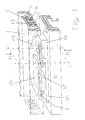
- Fig.1 shows a section of a Window / a door.
- the entire frame is made by Plastic hollow profiles formed.
- At least the frame 11 additionally shows a metal reinforcement 34 which in a cavity of the frame 11 through is plugged in.
- On the Falz Kunststoffseite 35 of Blendrahmens 11 is a so-called closing piece 10th attached and firmly connected to the frame 11.
- the closing piece 10 is advantageous with continuous screws against the frame 11th screwed, the screws in particular also penetrate the metal reinforcement 34 and on this Do the closing piece 10 fixed to the frame 11th anchor.
- here has the sash 1, the fitting groove 5 on.
- the fitting consisting from drive rod 8 and cover rail 7, at least in the longitudinal region of the attached to him Schöpartners 12 with retraction slot 25 by means of a Tray 5 held behind engaging backup plate 13 becomes.
- This backup plate 13 engages behind the Plastic profile of the sash 1 and is in the direction to the frame 11 either with the drive rod. 8 or connected to the cover rail 7 of the fitting 6.
- the backup plate 13 support in the trailing area on the sash 1, provided when levering the sash 1 the ambiguous mating Mushroom pin retraction slot (9-25) is loaded in the pulling direction. Therefore, the so forms battered casement 1 a structurally only below extreme power unit to be separated with the frame 11.
- Essential aspect for the best lever protection is therefore the combination of one or several closing partners 12 with Einfahrschlitz 25 am Wing frame 1 and the underlying arrangement of engaging behind backup plate 13 such that drive rod 8 and cover rail 7 of the fitting not only by means of the locking plate 13 against pulling out are protected from the hardware, but also as a result the flat-attached closing partner 12 with Einfahrschlitz 25 largely secured against deflection.
- the backup plate 13 can be any Behind the wing frame 1 engage behind.
- a projection of the fitting groove 5 is underrun become. This offers the advantage that known per se Plastic profiles continue without necessary modification are usable.
- Figures 1 and 4 are consistent in that that there Einfahrschlitz 25 and mushroom pin 9 sublime the drive rod 8 sit. They form a so-called first Closing part.
- the connection plate 26 lies with its flat back surface 27 close to the opposite surface the adjacent cover rail 7 and is over the in 3 and already described espagnolette bolts 36 moved together with the drive rod 8.
- Retraction slot 25 and mushroom pin 9 on the drive rod 8 are another mushroom pin 9 and an associated Einfahrschlitz 25 assigned to the frame 11.
- the latter two closing elements sit on another Connection plate 26 and form the so-called second closing part. Consequently, each one of the closing parts fixed with the fitting 6 and the other of the Locking parts firmly connected to the frame 11.
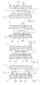
- FIGS. 5 and 6 show further embodiments.
- the closing part 12 which is connected to the drive rod 8, a lateral opened slot 28, in which the mushroom pin 9, which is rigidly connected to the frame 11, can retract laterally. After the mushroom pin 9 um a degree in the lateral slot 28 retracted is, he reaches a longitudinal plane in the associated Lock piece 12. On both sides of the side slot 28 extends in this longitudinal plane to both longitudinal directions the fitting 6 of the retraction slot 25, as above described.
- the closing piece 12 which is connected to the drive rod 8, shown in the Middle position, therefore, the sash 1 opposite opened or closed the frame 11 become. If the sash 1 is closed, is then via the handle 33, the drive rod. 8 set in motion. In this case, the closing piece 12th driven accordingly and the associated mushroom bolt 9 on the frame 11 can in the associated Retract entry slot 25.
- the fitting groove 5 forms a longitudinal Material recess on the casement 1.
- the fitting groove 5 has two opposite ones Projections 14 which the narrowest cross-section of Define fitting groove 5.
- Projections 14 which the narrowest cross-section of Define fitting groove 5.
- Toward the glass side of the Sash frame extends the fitting groove 5 behind the projections 14 and thus forms an undercut Area.
- the fitting groove serves 5 for receiving a window fitting 6.
- Window fitting 6 consists of a cover rail. 7 and a longitudinally guided drive rod 8.
- cover rail 7 by means of screws corresponding slots in the drive rod 8 am Basically the fitting groove 5 bolted and opposite held the sash.
- mushrooms bolts in pairs be provided (see EP 0 628 691), namely a mushroom bolt for the closed position and a mushroom bolt for the tilting position of the sash.
- the extended area 15 of the fitting groove takes 5, the securing plate 13, whose width 16 greater than that reduced by the projections 14 Width 15 of the fitting groove 5 is.
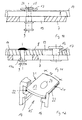
- Figure 8 shows that the inlet opening 20 for the locking plate 13 end of the frame spar 2 is created by a material recess.
- the inlet opening 20 is in the range Miter 4 arranged, but this without limitation of the invention. To this end it only requires one milled miter area 4 where the fittings of the frame spars 2,3 collide. Inevitably, this results end of the frame spar 2, the inlet opening 20 for the window fitting 6 according to the invention.
- the associated closing part 10 on the frame 11 has on the side facing the Einfahrschlitz 25 of the closing part 12 on the drive rod 8, a mushroom pin 9, while the opposite end of the closing part 10 on the frame 11 with a mushroom pin 9 on the fitting. 6 provided Einfahrschlitz 25 is provided. Within the clearance between the mushroom pin 9 and retracting slot 25 of the closing part 10 on the frame 11, the associated closing part 12 on the drive rod 8 is movable such that either the right closing pair, the left closing pair or no closing pairing is engaged. These three positions correspond to the closed position of the window, the open position of the window, the tilted position of the window. Notwithstanding this, Fig.5 shows that it can also be provided to strike only a mushroom pin on the frame 11.
- the closing part 12 of the drive rod 8 has a central Einfahrschlitz 25, from which extends in each case a longitudinal direction to the drive rod 8 coming into engagement with the mushroom pin 9 Einfahrschlitz 25.
- three positions are provided: Either the mushroom pin 9 is engaged with the right Einfahrschlitz 25 in the middle position unhindered from the closing part 12 moved out, in the left end position with the other Einfahrschlitz 25.
- the closed position, the open position, the tilted position of the sash are realized and still in the closed position and in the tilted position a tensile and alshebelête connection between sash and frame 11th
- the attachment of the closing parts on the frame 11 can be useful in each case by screwing with the usual in such windows inside metallic reinforcement part done. Possibly. can also add to the pull-out safety increase, screws with raised threads be provided. In such screws is the Core diameter in relation to the nominal diameter much smaller to these screws with appropriate Rear engagement zone on the metallic reinforcement profile to be attacked.
Landscapes
- Engineering & Computer Science (AREA)
- Mechanical Engineering (AREA)
- Window Of Vehicle (AREA)
- Power-Operated Mechanisms For Wings (AREA)
- Hinges (AREA)
- Wing Frames And Configurations (AREA)
Description
- Fig.1
- ein erstes Ausführungsbeispiel der Erfindung,
- Fig.2
- einen Querschnitt der Darstellung gemäß Fig.1 entlang der Linie II-II,
- Fig.3
- eine Detailansicht der Darstellung gemäß Fig.1 mit Deckschiene, Treibstange und Hintergreifplatte,
- Fig.4 bis 7
- weitere Variationsmöglichkeiten der Erfindung,
- Fig.8
- Einzelheiten zur Hintergreifplatte,
- Fig.9
- Querschnittsansicht eines Fensters/einer Tür,
- Fig.10
- ein Ausführungsbeispiel mit Sicherungsplatte fest mit der Treibstange verbunden,
- Fig.11
- ein Ausführungsbeispiel mit Sicherungsplatte fest mit der Deckschiene verbunden,
- Fig. 12
- Sicherungsplatte mit Verzahnung entlang ihrer Längskanten, und
- Fig.13
- Ansicht eines Fensters/einer Tür.
Entweder ist der Pilzbolzen 9 mit dem rechten Einfahrschlitz 25 in Eingriff, in der mittleren Stellung ungehindert aus dem Schließteil 12 herausfahrbar, in der linken Endstellung mit dem anderen Einfahrschlitz 25. Auf diese Weise sind wiederum die Schließstellung, die Offenstellung, die Kippstellung des Fensterflügels realisiert und trotzdem in der Schließstellung und in der Kippstellung eine zugfeste und aufhebelsichere Verbindung zwischen Flügelrahmen und Blendrahmen 11.
- 1
- Flügelrahmen/Fenster
- 2
- Rahmenholm
- 3
- Rahmenholm
- 4
- Gehrungsstelle
- 5
- Beschlagnut
- 6
- Fensterbeschlag
- 7
- Deckschiene
- 8
- Treibstange
- 9
- Pilzbolzen
- 10
- Schließstück
- 11
- Blendrahmen
- 12
- Längsbereich des Schließpartners an der Treibstange
- 13
- Sicherungsplatte
- 14
- Vorsprung
- 15
- erweiterter Bereich
- 16
- Breite der Sicherungsplatte
- 17
- Bolzen für Sicherungsplatte
- 17a
- Bolzen für Pilzknopf
- 18
- Bolzenkopf
- 19
- Langloch in der Treibstange
- 20
- Eintrittsöffnung
- 21
- Längskante
- 22
- Verzahnung
- 23
- Haltebereich
- 24
- Versenkung
- 25
- Einfahrschlitz
- 26
- Verbindungsplatte
- 27
- Rückenfläche
- 28
- seitlicher Schlitz
- 30
- horizontale Kippachse
- 31
- vertikale Drehachse
- 32
- Schließpaarung
- 33
- Handgriff
- 34
- Metallverstärkung
- 35
- Falzluftseite
- 36
- Treibstangenbolzen
- 37
- Langloch
Claims (16)
- Fenster/Tür mit Dreh-Kipp-Beschlag, bestehend aus in einer Beschlagnut (5) des Flügelrahmens eingelegten Treibstange (8) und Deckschiene (7), wobei am unteren Querholm zwischen Blendrahmen und Flügelrahmen sowohl in der Schließstellung als auch in der Kippstellung zusammengreifende Schließpartner vorgesehen sind, die aus endseitig geöffneten Einfahrschlitzen und mittels des Beschlags relativ dazu in Längsrichtung der Einfahrschlitze beweglichen Pilzbolzen bestehen, wobei jeweils ein Schließpartner am Blendrahmen und der andere Schließpartner am Flügelrahmen angebracht ist, dadurch gekennzeichnet, daß von den Schließpartnern der Schließstellung und der Kippstellung zumindest einer der Schließpartner mit Einfahrschlitz (25) starr mit der Treibstange (8) des Beschlags (6) verbunden und der zugeordnete Pilzbolzen (9) relativ dazu ortsfest angeordnet ist und daß Treibstange (8) und Deckschiene (7) zumindest im Längsbereich (12) des Schließpartners an der Treibstange mit einer hinter der Beschlagnut (5) gegen den Flügelrahmen abgestützten Sicherungsplatte (13) gehalten werden.
- Fenster/Tür nach Anspruch 1, dadurch gekennzeichnet, daß die Sicherungsplatte (13) die Beschlagnut (5) hintergreift.
- Fenster/Tür nach Anspruch 1 oder 2, dadurch gekennzeichnet, daß der mit der Treibstange (8) des Beschlags verbundene Schließpartner mindestens über die Länge des Einfahrschlitzes an der Deckschiene (7) des Beschlags angefügt und an der Treibstange (8) befestigt ist.
- Fenster/Tür nach Anspruch 2, dadurch gekennzeichnet, daß die Sicherungsplatte (13) einen Vorsprung der Beschlagnut (5) hintergreift.
- Fenster/Tür nach einem der Ansprüche 1 bis 4, dadurch gekennzeichnet, daß der Flügelrahmen eine außerhalb des Haltebereichs liegende Eintrittsöffnung für die Sicherungsplatte (13) aufweist.
- Fenster/Tür nach einem der Ansprüche 1 bis 5, dadurch gekennzeichnet, daß die Sicherungsplatte (13) fest mit der Treibstange (8) verbunden und mit Bewegungsspiel in Längsrichtung innerhalb der Beschlagnut (5) gelagert ist.
- Fenster/Tür nach einem der Ansprüche 1 bis 5, dadurch gekennzeichnet, daß die Sicherungsplatte (13) mittels Bolzen (17) fest mit der Deckschiene (7) verbunden ist und daß der Bolzen (17) die Treibstange (8) im Bereich eines Langlochs (19) durchbricht.
- Fenster/Tür nach einem der Ansprüche 1 bis 5, dadurch gekennzeichnet, daß die Sicherungsplatte (13) zusammen mit Pilzbolzen (9) und Schließstück (10) im Endbereich des zugehörigen Rahmenholms (2) angeordnet ist.
- Fenster/Tür nach Anspruch 8, dadurch gekennzeichnet, daß der Fensterbeschlag (6) endseitig des Rahmenholms (2) endet und daß das freie Ende des Fensterbeschlags (6) dort mit der Sicherungsplatte (13) gehalten wird.
- Fenster/Tür nach einem der Ansprüche 5 bis 9, dadurch gekennzeichnet, daß die Eintrittsöffnung (20) durch quer zur Längsrichtung des Flügelrahmens liegende Materialausnehmung hergestellt ist.
- Fenster/Tür nach Anspruch 10, dadurch gekennzeichnet, daß die Eintrittsöffnung (20) endseitig des Rahmenholms (2) und vorzugsweise im Bereich der Gehrungsstelle (4) liegt.
- Fenster/Tür nach Anspruch 1 oder 2, dadurch gekennzeichnet, daß die Sicherungsplatte (13) unverdrehbar starr mit Treibstange (8) bzw. Deckschiene (7) verbunden ist und eine Breite (16) aufweist, welche der lichten Weite des erweiterten Bereichs (15) der Beschlagnut (5) entspricht.
- Fenster/Tür nach Anspruch 1 oder 2, dadurch gekennzeichnet, daß die Sicherungsplatte (13) an ihren dem Vorsprung (14) der Beschlagnut (5) zugewandten seitlichen Längskanten (21) mit einer in den Vorsprung (14) greifenden Verzahnung ausgestattet ist.
- Fenster/Tür nach Anspruch 1 oder 2, dadurch gekennzeichnet, daß Einfahrschlitz (25) und Pilzbolzen (9) auf einer Verbindungsplatte sitzen und erhaben an der Deckschiene gleiten (= 1. Schließteil) und daß zugeordneter Pilzbolzen und Einfahrschlitz auf einer weiteren Verbindungsplatte (= 2. Schließteil) am Blendrahmen sitzen, und daß Einfahrschlitz und Pilzbolzen des einen Schließteils zwischen Einfahrschlitz (25) und Pilzbolzen (9) des anderen Schließteils angeordnet und verfahrbar sind. (Fig.1,4)
- Fenster/Tür nach Anspruch 1 oder 2, dadurch gekennzeichnet, daß das/die mit der Treibstange (8) verbundene(n) Schließteil(e) (12) zwei nach außen endseitig offene Einfahrschlitze (25) aufweist(en), und daß mit dem Blendrahmen starr ein Pilzbolzenpaar verbunden ist, von denen jeweils ein Pilzbolzen (9) in der Schließstellung und der andere Pilzbolzen (9) in der Kippstellung mit einem der Einfahrschlitze (25) zusammenwirkt und daß, vorzugsweise beide Pilzbolzen auf gemeinsamer Verbindungsplatte (26) sitzen. (Fig.7)
- Fenster/Tür nach Anspruch 1 oder 2, dadurch gekennzeichnet, daß das Schließteil an der Treibstange (8) des Beschlags einen seitlich geöffneten Schlitz (28) und einen über den Seitenschlitz (28) zugänglichen Längsschlitz (25) aufweist, der sich - ausgehend von dem Seitenschlitz (28) - zu beiden Längsrichtungen des Beschlags (6) erstreckt und daß ein oder mehrere dicht beabstandete Pilzbolzen (9) mit diesem Längsschlitz (25) zusammenwirken, wobei der/die Pilzbolzen (9) der ortsfest am Blendrahmen (11) angeschlagen ist (sind), vorzugsweise auf einer Befestigungsplatte (26) angeordnet. (Fig.5,6)
Applications Claiming Priority (2)
| Application Number | Priority Date | Filing Date | Title |
|---|---|---|---|
| DE29513098U | 1995-08-16 | ||
| DE29513098U DE29513098U1 (de) | 1995-08-16 | 1995-08-16 | Fenster/Tür mit Dreh-Kipp-Beschlag |
Publications (4)
| Publication Number | Publication Date |
|---|---|
| EP0761920A2 EP0761920A2 (de) | 1997-03-12 |
| EP0761920A3 EP0761920A3 (de) | 1997-08-20 |
| EP0761920B1 EP0761920B1 (de) | 2000-01-05 |
| EP0761920B2 true EP0761920B2 (de) | 2005-05-18 |
Family
ID=8011783
Family Applications (1)
| Application Number | Title | Priority Date | Filing Date |
|---|---|---|---|
| EP96112699A Expired - Lifetime EP0761920B2 (de) | 1995-08-16 | 1996-08-07 | Fenster/Tür mit Dreh-Kipp-Beschlag |
Country Status (4)
| Country | Link |
|---|---|
| EP (1) | EP0761920B2 (de) |
| AT (1) | ATE188530T1 (de) |
| DE (2) | DE29513098U1 (de) |
| DK (1) | DK0761920T3 (de) |
Families Citing this family (7)
| Publication number | Priority date | Publication date | Assignee | Title |
|---|---|---|---|---|
| DE19534253A1 (de) * | 1995-09-15 | 1997-03-20 | Pax Gmbh | Fenster/Tür mit Schließstellen zwischen Dreh-Kipp-Flügelrahmen und ortsfestem Blendrahmen |
| DE19625946C2 (de) * | 1996-06-28 | 1998-10-29 | Pax Gmbh | Kombination aus Flügelrahmen und Blendrahmen eines Fensters/einer Tür |
| DE19739407C2 (de) | 1997-09-09 | 2001-05-17 | Pax Gmbh | Fenster/Tür |
| DE50308957D1 (de) * | 2002-10-01 | 2008-02-21 | Somfy Sas | Verriegelnde Beschlagmechanik für ein Drehkippfenster oder eine Drehkipptüre |
| DE102012200120A1 (de) * | 2011-01-12 | 2012-07-12 | Hautau Gmbh | Treibstangenbeschlag und Arbeitsverfahren für einen schmalen Flügelrahmen |
| DE102012202151A1 (de) * | 2012-02-13 | 2013-08-14 | Hautau Gmbh | Treibstangenbeschlag mit Spaltlüftungs- und Verriegelungsfunktion |
| DE102013100098A1 (de) * | 2013-01-07 | 2014-07-10 | Pax Ag | Verglasung für eine Tür oder ein Fenster |
Family Cites Families (5)
| Publication number | Priority date | Publication date | Assignee | Title |
|---|---|---|---|---|
| DE7838570U1 (de) * | 1978-12-27 | 1979-04-12 | Siegenia-Frank Kg, 5900 Siegen | Fenster, tuer o.dgl. aus kunststoff- profilen |
| DE3329414A1 (de) * | 1983-08-13 | 1985-02-21 | Ulrich 6531 Gensingen Kreusel | Einhand-drehkipp-beschlag fuer ein fenster |
| DE8614557U1 (de) * | 1986-05-30 | 1986-07-17 | Siegenia-Frank Kg, 5900 Siegen | Verhakungsvorrichtung zwischen dem Flügel und dem feststehenden Rahmen von Fenstern, Türen od.dgl. |
| DE4009637C2 (de) * | 1989-07-06 | 1994-04-21 | Saelzer Sicherheitstechnik | Vorrichtung zur Sicherung eines Tür- oder Fensterflügelrahmens |
| DE9308472U1 (de) * | 1993-06-07 | 1993-09-02 | Pax Schweikhard GmbH, 55218 Ingelheim | Dreh-Kipp-Beschlag für Fenster, Türen o.dgl. |
-
1995
- 1995-08-16 DE DE29513098U patent/DE29513098U1/de not_active Expired - Lifetime
-
1996
- 1996-08-07 DK DK96112699T patent/DK0761920T3/da active
- 1996-08-07 DE DE59604096T patent/DE59604096D1/de not_active Expired - Lifetime
- 1996-08-07 EP EP96112699A patent/EP0761920B2/de not_active Expired - Lifetime
- 1996-08-07 AT AT96112699T patent/ATE188530T1/de not_active IP Right Cessation
Also Published As
| Publication number | Publication date |
|---|---|
| ATE188530T1 (de) | 2000-01-15 |
| EP0761920A2 (de) | 1997-03-12 |
| DE29513098U1 (de) | 1996-12-19 |
| DE59604096D1 (de) | 2000-02-10 |
| DK0761920T3 (da) | 2000-05-29 |
| EP0761920B1 (de) | 2000-01-05 |
| EP0761920A3 (de) | 1997-08-20 |
Similar Documents
| Publication | Publication Date | Title |
|---|---|---|
| EP3798390B2 (de) | Faltanlage | |
| EP0761920B2 (de) | Fenster/Tür mit Dreh-Kipp-Beschlag | |
| EP0433623B1 (de) | Verriegelungsvorrichtung für ein Fenster, eine Tür od.dgl. | |
| EP0493689B1 (de) | Treibstangenbeschlag für Fenster, Türen od.dgl. | |
| DE19521601C1 (de) | Fenster, Tür oder dergleichen | |
| EP1002916A1 (de) | Zusatzschloss für Flügel von Türen, Fenstern od. dgl | |
| EP0573819A2 (de) | Fenster, Tür od. dgl. mit Beschlägen für den Einbau in abgestufte Profilnuten der Flügel | |
| EP0844348A1 (de) | Band für Türen oder Fenster | |
| EP0733761B1 (de) | Flügelrahmen | |
| EP1008713A1 (de) | Verriegelungsvorrichtung | |
| DE2243916C2 (de) | Kippriegel Verschluß für Drehkippfenster, -türen od.dgl. | |
| DE4200868A1 (de) | Zusatz-schliesseinrichtung fuer fenster | |
| DE10005884C2 (de) | Treibstangenbeschlag | |
| DE19507481C1 (de) | Abschließbarer Fenstergriff | |
| DE29615631U1 (de) | Sicherungseinrichtung | |
| DE3215452A1 (de) | Eckumlenkung fuer treibstangenbeschlaege von fenstern, tueren od. dgl. | |
| EP0158069B2 (de) | Schliess- und Verriegelungsvorrichtung für eine Tür od. dgl. | |
| WO2025247934A1 (de) | Verriegelungsbeschlag und tür- oder fensteranordnung | |
| DE8426285U1 (de) | Schliessplatte fuer fenster- und tuerverschluesse od. dgl. | |
| EP0625235A1 (de) | Sicherheitstür und sicherheitsvorrichtung zum einbau in eine tür | |
| EP0276379B1 (de) | Befestigungsvorrichtung für Beschlagteile | |
| EP4512981A1 (de) | Gegenkasten für einen standflügelverschluss | |
| EP0756054A2 (de) | Fenster, Tür oder dergleichen | |
| DE8901988U1 (de) | Sicherungseinrichtung für Fenster | |
| DE29800306U1 (de) | Beschlag für einen Flügelrahmen von Fenstern oder Türen |
Legal Events
| Date | Code | Title | Description |
|---|---|---|---|
| PUAI | Public reference made under article 153(3) epc to a published international application that has entered the european phase |
Free format text: ORIGINAL CODE: 0009012 |
|
| AK | Designated contracting states |
Kind code of ref document: A2 Designated state(s): AT CH DE DK FR GB IT LI SE |
|
| PUAL | Search report despatched |
Free format text: ORIGINAL CODE: 0009013 |
|
| AK | Designated contracting states |
Kind code of ref document: A3 Designated state(s): AT CH DE DK FR GB IT LI SE |
|
| 17P | Request for examination filed |
Effective date: 19971111 |
|
| GRAG | Despatch of communication of intention to grant |
Free format text: ORIGINAL CODE: EPIDOS AGRA |
|
| 17Q | First examination report despatched |
Effective date: 19981123 |
|
| GRAG | Despatch of communication of intention to grant |
Free format text: ORIGINAL CODE: EPIDOS AGRA |
|
| GRAH | Despatch of communication of intention to grant a patent |
Free format text: ORIGINAL CODE: EPIDOS IGRA |
|
| GRAH | Despatch of communication of intention to grant a patent |
Free format text: ORIGINAL CODE: EPIDOS IGRA |
|
| GRAA | (expected) grant |
Free format text: ORIGINAL CODE: 0009210 |
|
| AK | Designated contracting states |
Kind code of ref document: B1 Designated state(s): AT CH DE DK FR GB IT LI SE |
|
| REF | Corresponds to: |
Ref document number: 188530 Country of ref document: AT Date of ref document: 20000115 Kind code of ref document: T |
|
| REG | Reference to a national code |
Ref country code: CH Ref legal event code: NV Representative=s name: E. BLUM & CO. PATENTANWAELTE Ref country code: CH Ref legal event code: EP |
|
| REF | Corresponds to: |
Ref document number: 59604096 Country of ref document: DE Date of ref document: 20000210 |
|
| ITF | It: translation for a ep patent filed | ||
| GBT | Gb: translation of ep patent filed (gb section 77(6)(a)/1977) |
Effective date: 20000307 |
|
| ET | Fr: translation filed | ||
| REG | Reference to a national code |
Ref country code: DK Ref legal event code: T3 |
|
| PGFP | Annual fee paid to national office [announced via postgrant information from national office to epo] |
Ref country code: SE Payment date: 20000807 Year of fee payment: 5 Ref country code: DK Payment date: 20000807 Year of fee payment: 5 |
|
| PGFP | Annual fee paid to national office [announced via postgrant information from national office to epo] |
Ref country code: GB Payment date: 20000809 Year of fee payment: 5 |
|
| PLBI | Opposition filed |
Free format text: ORIGINAL CODE: 0009260 |
|
| PLBQ | Unpublished change to opponent data |
Free format text: ORIGINAL CODE: EPIDOS OPPO |
|
| PLBI | Opposition filed |
Free format text: ORIGINAL CODE: 0009260 |
|
| PLBF | Reply of patent proprietor to notice(s) of opposition |
Free format text: ORIGINAL CODE: EPIDOS OBSO |
|
| 26 | Opposition filed |
Opponent name: SIEGENIA-FRANK KG Effective date: 20000925 |
|
| 26 | Opposition filed |
Opponent name: SCHUECO INTERNATIONAL KG Effective date: 20001004 Opponent name: SIEGENIA-FRANK KG Effective date: 20000925 |
|
| PLBF | Reply of patent proprietor to notice(s) of opposition |
Free format text: ORIGINAL CODE: EPIDOS OBSO |
|
| 29U | Proceedings interrupted after grant according to rule 142 epc |
Effective date: 20010501 |
|
| 29W | Proceedings resumed after grant [after interruption of proceedings according to rule 142 epc] |
Effective date: 20011116 |
|
| PG25 | Lapsed in a contracting state [announced via postgrant information from national office to epo] |
Ref country code: GB Free format text: LAPSE BECAUSE OF NON-PAYMENT OF DUE FEES Effective date: 20010807 Ref country code: DK Free format text: LAPSE BECAUSE OF NON-PAYMENT OF DUE FEES Effective date: 20010807 |
|
| PG25 | Lapsed in a contracting state [announced via postgrant information from national office to epo] |
Ref country code: SE Free format text: LAPSE BECAUSE OF NON-PAYMENT OF DUE FEES Effective date: 20010808 |
|
| PLBF | Reply of patent proprietor to notice(s) of opposition |
Free format text: ORIGINAL CODE: EPIDOS OBSO |
|
| GBPC | Gb: european patent ceased through non-payment of renewal fee |
Effective date: 20010807 |
|
| EUG | Se: european patent has lapsed |
Ref document number: 96112699.2 |
|
| PLBF | Reply of patent proprietor to notice(s) of opposition |
Free format text: ORIGINAL CODE: EPIDOS OBSO |
|
| REG | Reference to a national code |
Ref country code: DK Ref legal event code: EBP |
|
| PLBF | Reply of patent proprietor to notice(s) of opposition |
Free format text: ORIGINAL CODE: EPIDOS OBSO |
|
| PLBF | Reply of patent proprietor to notice(s) of opposition |
Free format text: ORIGINAL CODE: EPIDOS OBSO |
|
| PLAB | Opposition data, opponent's data or that of the opponent's representative modified |
Free format text: ORIGINAL CODE: 0009299OPPO |
|
| R26 | Opposition filed (corrected) |
Opponent name: SCHUECO INTERNATIONAL KG Effective date: 20001004 Opponent name: SIEGENIA-AUBI KG. Effective date: 20000925 |
|
| PGFP | Annual fee paid to national office [announced via postgrant information from national office to epo] |
Ref country code: AT Payment date: 20030813 Year of fee payment: 8 |
|
| PGFP | Annual fee paid to national office [announced via postgrant information from national office to epo] |
Ref country code: FR Payment date: 20030825 Year of fee payment: 8 |
|
| PGFP | Annual fee paid to national office [announced via postgrant information from national office to epo] |
Ref country code: CH Payment date: 20031013 Year of fee payment: 8 |
|
| PG25 | Lapsed in a contracting state [announced via postgrant information from national office to epo] |
Ref country code: AT Free format text: LAPSE BECAUSE OF NON-PAYMENT OF DUE FEES Effective date: 20040807 |
|
| PG25 | Lapsed in a contracting state [announced via postgrant information from national office to epo] |
Ref country code: LI Free format text: LAPSE BECAUSE OF NON-PAYMENT OF DUE FEES Effective date: 20040831 Ref country code: CH Free format text: LAPSE BECAUSE OF NON-PAYMENT OF DUE FEES Effective date: 20040831 |
|
| PUAH | Patent maintained in amended form |
Free format text: ORIGINAL CODE: 0009272 |
|
| STAA | Information on the status of an ep patent application or granted ep patent |
Free format text: STATUS: PATENT MAINTAINED AS AMENDED |
|
| REG | Reference to a national code |
Ref country code: CH Ref legal event code: PL |
|
| PG25 | Lapsed in a contracting state [announced via postgrant information from national office to epo] |
Ref country code: FR Free format text: LAPSE BECAUSE OF NON-PAYMENT OF DUE FEES Effective date: 20050429 |
|
| 27A | Patent maintained in amended form |
Effective date: 20050518 |
|
| AK | Designated contracting states |
Kind code of ref document: B2 Designated state(s): AT CH DE DK FR GB IT LI SE |
|
| REG | Reference to a national code |
Ref country code: FR Ref legal event code: ST |
|
| PG25 | Lapsed in a contracting state [announced via postgrant information from national office to epo] |
Ref country code: IT Free format text: LAPSE BECAUSE OF NON-PAYMENT OF DUE FEES Effective date: 20050807 |
|
| EN | Fr: translation not filed | ||
| PLAB | Opposition data, opponent's data or that of the opponent's representative modified |
Free format text: ORIGINAL CODE: 0009299OPPO |
|
| REG | Reference to a national code |
Ref country code: DE Ref legal event code: R082 Ref document number: 59604096 Country of ref document: DE Representative=s name: MUELLER, JOCHEN, DIPL.-ING., DE Ref country code: DE Ref legal event code: R082 Ref document number: 59604096 Country of ref document: DE Representative=s name: JOCHEN MUELLER, DE |
|
| PGFP | Annual fee paid to national office [announced via postgrant information from national office to epo] |
Ref country code: DE Payment date: 20150820 Year of fee payment: 20 |
|
| REG | Reference to a national code |
Ref country code: DE Ref legal event code: R071 Ref document number: 59604096 Country of ref document: DE |