EP3793802B1 - Dispositif de tri et rail d'alimentation pour préformes en matière plastique - Google Patents
Dispositif de tri et rail d'alimentation pour préformes en matière plastique Download PDFInfo
- Publication number
- EP3793802B1 EP3793802B1 EP19732330.6A EP19732330A EP3793802B1 EP 3793802 B1 EP3793802 B1 EP 3793802B1 EP 19732330 A EP19732330 A EP 19732330A EP 3793802 B1 EP3793802 B1 EP 3793802B1
- Authority
- EP
- European Patent Office
- Prior art keywords
- plastic preforms
- adjustment
- transport
- sorting device
- transport direction
- Prior art date
- Legal status (The legal status is an assumption and is not a legal conclusion. Google has not performed a legal analysis and makes no representation as to the accuracy of the status listed.)
- Active
Links
- 230000032258 transport Effects 0.000 claims description 124
- 230000007246 mechanism Effects 0.000 claims description 23
- 230000008878 coupling Effects 0.000 claims description 14
- 238000010168 coupling process Methods 0.000 claims description 14
- 238000005859 coupling reaction Methods 0.000 claims description 14
- 238000000034 method Methods 0.000 claims description 11
- 238000010438 heat treatment Methods 0.000 description 26
- 230000000694 effects Effects 0.000 description 10
- 239000012530 fluid Substances 0.000 description 8
- 230000008859 change Effects 0.000 description 6
- 238000006243 chemical reaction Methods 0.000 description 5
- 230000008569 process Effects 0.000 description 5
- 238000000071 blow moulding Methods 0.000 description 3
- 230000001419 dependent effect Effects 0.000 description 3
- 238000006073 displacement reaction Methods 0.000 description 3
- 238000004519 manufacturing process Methods 0.000 description 3
- 239000000725 suspension Substances 0.000 description 3
- 230000008901 benefit Effects 0.000 description 2
- 230000005540 biological transmission Effects 0.000 description 2
- 238000005516 engineering process Methods 0.000 description 2
- 230000003134 recirculating effect Effects 0.000 description 2
- 239000013590 bulk material Substances 0.000 description 1
- 238000011161 development Methods 0.000 description 1
- 230000018109 developmental process Effects 0.000 description 1
- 230000009347 mechanical transmission Effects 0.000 description 1
- 230000004044 response Effects 0.000 description 1
- 230000001360 synchronised effect Effects 0.000 description 1
Images


Classifications
-
- B—PERFORMING OPERATIONS; TRANSPORTING
- B29—WORKING OF PLASTICS; WORKING OF SUBSTANCES IN A PLASTIC STATE IN GENERAL
- B29C—SHAPING OR JOINING OF PLASTICS; SHAPING OF MATERIAL IN A PLASTIC STATE, NOT OTHERWISE PROVIDED FOR; AFTER-TREATMENT OF THE SHAPED PRODUCTS, e.g. REPAIRING
- B29C49/00—Blow-moulding, i.e. blowing a preform or parison to a desired shape within a mould; Apparatus therefor
- B29C49/02—Combined blow-moulding and manufacture of the preform or the parison
- B29C49/06—Injection blow-moulding
-
- B—PERFORMING OPERATIONS; TRANSPORTING
- B29—WORKING OF PLASTICS; WORKING OF SUBSTANCES IN A PLASTIC STATE IN GENERAL
- B29C—SHAPING OR JOINING OF PLASTICS; SHAPING OF MATERIAL IN A PLASTIC STATE, NOT OTHERWISE PROVIDED FOR; AFTER-TREATMENT OF THE SHAPED PRODUCTS, e.g. REPAIRING
- B29C49/00—Blow-moulding, i.e. blowing a preform or parison to a desired shape within a mould; Apparatus therefor
- B29C49/42—Component parts, details or accessories; Auxiliary operations
- B29C49/4205—Handling means, e.g. transfer, loading or discharging means
-
- B—PERFORMING OPERATIONS; TRANSPORTING
- B29—WORKING OF PLASTICS; WORKING OF SUBSTANCES IN A PLASTIC STATE IN GENERAL
- B29C—SHAPING OR JOINING OF PLASTICS; SHAPING OF MATERIAL IN A PLASTIC STATE, NOT OTHERWISE PROVIDED FOR; AFTER-TREATMENT OF THE SHAPED PRODUCTS, e.g. REPAIRING
- B29C49/00—Blow-moulding, i.e. blowing a preform or parison to a desired shape within a mould; Apparatus therefor
- B29C49/28—Blow-moulding apparatus
- B29C49/30—Blow-moulding apparatus having movable moulds or mould parts
- B29C49/36—Blow-moulding apparatus having movable moulds or mould parts rotatable about one axis
-
- B—PERFORMING OPERATIONS; TRANSPORTING
- B29—WORKING OF PLASTICS; WORKING OF SUBSTANCES IN A PLASTIC STATE IN GENERAL
- B29C—SHAPING OR JOINING OF PLASTICS; SHAPING OF MATERIAL IN A PLASTIC STATE, NOT OTHERWISE PROVIDED FOR; AFTER-TREATMENT OF THE SHAPED PRODUCTS, e.g. REPAIRING
- B29C49/00—Blow-moulding, i.e. blowing a preform or parison to a desired shape within a mould; Apparatus therefor
- B29C49/42—Component parts, details or accessories; Auxiliary operations
- B29C49/4205—Handling means, e.g. transfer, loading or discharging means
- B29C49/42051—Means for stripping, aligning or de-stacking
- B29C49/42057—Aligning disorderly arranged preforms, e.g. delivered disorderly
-
- B—PERFORMING OPERATIONS; TRANSPORTING
- B29—WORKING OF PLASTICS; WORKING OF SUBSTANCES IN A PLASTIC STATE IN GENERAL
- B29C—SHAPING OR JOINING OF PLASTICS; SHAPING OF MATERIAL IN A PLASTIC STATE, NOT OTHERWISE PROVIDED FOR; AFTER-TREATMENT OF THE SHAPED PRODUCTS, e.g. REPAIRING
- B29C49/00—Blow-moulding, i.e. blowing a preform or parison to a desired shape within a mould; Apparatus therefor
- B29C49/02—Combined blow-moulding and manufacture of the preform or the parison
- B29C2049/023—Combined blow-moulding and manufacture of the preform or the parison using inherent heat of the preform, i.e. 1 step blow moulding
-
- B—PERFORMING OPERATIONS; TRANSPORTING
- B29—WORKING OF PLASTICS; WORKING OF SUBSTANCES IN A PLASTIC STATE IN GENERAL
- B29C—SHAPING OR JOINING OF PLASTICS; SHAPING OF MATERIAL IN A PLASTIC STATE, NOT OTHERWISE PROVIDED FOR; AFTER-TREATMENT OF THE SHAPED PRODUCTS, e.g. REPAIRING
- B29C2949/00—Indexing scheme relating to blow-moulding
- B29C2949/07—Preforms or parisons characterised by their configuration
- B29C2949/0715—Preforms or parisons characterised by their configuration the preform having one end closed
-
- B—PERFORMING OPERATIONS; TRANSPORTING
- B29—WORKING OF PLASTICS; WORKING OF SUBSTANCES IN A PLASTIC STATE IN GENERAL
- B29C—SHAPING OR JOINING OF PLASTICS; SHAPING OF MATERIAL IN A PLASTIC STATE, NOT OTHERWISE PROVIDED FOR; AFTER-TREATMENT OF THE SHAPED PRODUCTS, e.g. REPAIRING
- B29C49/00—Blow-moulding, i.e. blowing a preform or parison to a desired shape within a mould; Apparatus therefor
- B29C49/42—Component parts, details or accessories; Auxiliary operations
- B29C49/4205—Handling means, e.g. transfer, loading or discharging means
- B29C49/42093—Transporting apparatus, e.g. slides, wheels or conveyors
- B29C49/42097—Sliding rails, e.g. inclined
-
- B—PERFORMING OPERATIONS; TRANSPORTING
- B29—WORKING OF PLASTICS; WORKING OF SUBSTANCES IN A PLASTIC STATE IN GENERAL
- B29C—SHAPING OR JOINING OF PLASTICS; SHAPING OF MATERIAL IN A PLASTIC STATE, NOT OTHERWISE PROVIDED FOR; AFTER-TREATMENT OF THE SHAPED PRODUCTS, e.g. REPAIRING
- B29C49/00—Blow-moulding, i.e. blowing a preform or parison to a desired shape within a mould; Apparatus therefor
- B29C49/42—Component parts, details or accessories; Auxiliary operations
- B29C49/4205—Handling means, e.g. transfer, loading or discharging means
- B29C49/42113—Means for manipulating the objects' position or orientation
- B29C49/42121—Changing the center-center distance
- B29C49/42122—Adapting to blow-mould cavity center-center distance
-
- B—PERFORMING OPERATIONS; TRANSPORTING
- B29—WORKING OF PLASTICS; WORKING OF SUBSTANCES IN A PLASTIC STATE IN GENERAL
- B29C—SHAPING OR JOINING OF PLASTICS; SHAPING OF MATERIAL IN A PLASTIC STATE, NOT OTHERWISE PROVIDED FOR; AFTER-TREATMENT OF THE SHAPED PRODUCTS, e.g. REPAIRING
- B29C49/00—Blow-moulding, i.e. blowing a preform or parison to a desired shape within a mould; Apparatus therefor
- B29C49/42—Component parts, details or accessories; Auxiliary operations
- B29C49/64—Heating or cooling preforms, parisons or blown articles
- B29C49/68—Ovens specially adapted for heating preforms or parisons
-
- B—PERFORMING OPERATIONS; TRANSPORTING
- B29—WORKING OF PLASTICS; WORKING OF SUBSTANCES IN A PLASTIC STATE IN GENERAL
- B29C—SHAPING OR JOINING OF PLASTICS; SHAPING OF MATERIAL IN A PLASTIC STATE, NOT OTHERWISE PROVIDED FOR; AFTER-TREATMENT OF THE SHAPED PRODUCTS, e.g. REPAIRING
- B29C49/00—Blow-moulding, i.e. blowing a preform or parison to a desired shape within a mould; Apparatus therefor
- B29C49/42—Component parts, details or accessories; Auxiliary operations
- B29C49/78—Measuring, controlling or regulating
-
- B—PERFORMING OPERATIONS; TRANSPORTING
- B29—WORKING OF PLASTICS; WORKING OF SUBSTANCES IN A PLASTIC STATE IN GENERAL
- B29L—INDEXING SCHEME ASSOCIATED WITH SUBCLASS B29C, RELATING TO PARTICULAR ARTICLES
- B29L2031/00—Other particular articles
- B29L2031/712—Containers; Packaging elements or accessories, Packages
- B29L2031/7158—Bottles
Definitions
- the present invention relates to a device for producing plastic containers. It is known that so-called plastic preforms are first heated and then shaped into plastic containers in a heated state. In this case, plastic preforms are usually first sorted, for example starting from a loose bed, and then fed to a heating device in a sorted state. In the prior art, preform feed rails are used, which represent the remaining element between, for example, a sorting device, such as a roller sorter, and a blow molding machine, for example the oven of the blow molding machine.
- a sorting device such as a roller sorter
- a blow molding machine for example the oven of the blow molding machine.
- a roll sorter aligns and lines up the plastic preforms from a loose bulk material to form a regular arrangement.
- the aligned plastic preforms are then fed to a blow molding machine via the outlet fitting and the feed rail.
- a roller spacing and, for example, a kicker wheel or a guide tongue must be specifically defined and adjusted for each geometry of the plastic preforms.
- a roller sorter is known from the internal state of the art, in which the adjustment of a roller spacing to one another takes place on one side, that is to say that only one of these rollers is moved, which can be done, for example, by means of a handwheel and a counter.
- a mechanical movement of an adjusting wheel is transmitted here, for example, via a line shaft to trapezoidal spindles of linear units.
- the manual setting activities lead to incorrect values, which have a negative effect on the restart behavior and production after a changeover process.
- the changeover activities take up working time.
- the present invention is therefore based on the object of simplifying such conversions of a corresponding device and preferably also making them more precise. According to the invention, these objects are achieved by the subject matter of the independent patent claims. Advantageous embodiments and developments are the subject of the dependent claims.
- a device according to the invention for transporting plastic preforms has a sorting device which is suitable and intended for sorting plastic preforms and which transports the plastic preforms in a predetermined transport direction. Furthermore, a transport device arranged downstream of the sorting device in the transport direction is provided, with this transport device having a first carrier rail for carrying the plastic preforms and a second carrier rail for carrying the plastic preforms, and the plastic preforms can be transported between this first carrier rail and the second carrier rail. In this case, these carrier rails extend along the transport direction, with the sorting device having two rollers spaced apart from one another, between which the plastic preforms can be guided.
- the device has an adjustment mechanism for adjusting at least one lateral distance between these carrier rails, this adjustment mechanism having a plurality of adjustment units which are arranged one behind the other along the transport direction, these adjustment units each enabling the lateral distance to be adjusted and these adjustment units being coupled to one another in particular mechanically in this way are that the adjustment units can be adjusted together.
- this adjusting mechanism it is possible to change the distance between these two support rails centrally, for example. In this way, the device can be changed over to different plastic preforms. It is possible, for example, for this adjusting mechanism to have a spindle drive or a rack or similar mechanical elements.
- each of the adjusting units would also have its own drive and for these drives to be controlled together. In this way, there would be a control-side coupling between the drives and thus also between the adjusting units.
- the adjustment units are coupled to one another by means of at least one mechanical coupling device.
- the coupling device has at least one rod-like body that can be rotated or displaced along its longitudinal direction on.
- these are coupling rods which are rotatable and which can advantageously act on the individual adjustment units, for example via toothing.
- several adjustment units can be changed simultaneously and in the same way, for example by a central adjustment unit or a central adjustment device.
- These adjustment units can preferably have gear mechanisms that can be driven by a central shaft. This gear mechanism may include a bevel gear, for example.
- the device has a drive device for driving the adjustment units.
- a drive device for driving the adjustment units.
- one or possibly also several central motors can be provided, which can effect the adjustment on several adjustment units.
- the individual adjustment units of a plastic preform feed rail be replaced by a central adjustment.
- mechanical adjustment units can be installed at the suspension points of the support rails, a hold-down device or possibly also a guide for the plastic preforms, which are preferably coupled to one another and can then be adjusted from a central point.
- the mechanical adjustment units are preferably in the form of linear units; the adjustment is particularly preferably carried out mechanically, for example via a spindle drive.
- Other designs, such as toothed racks or the like, are also conceivable.
- the adjustment units can be coupled mechanically for each functional element (support strip, hold-down device or guide device), for example with a continuous shaft.
- a maximum of five adjustment units can be set at an easily accessible point on a feed rail.
- This point can be, for example, at an upper or lower end of the rail.
- a central electromotive adjustment can be provided, for example at two, three, four or five points.
- a central electromotive adjustment unit arranged decentrally, the coupling and synchronization of which preferably takes place via a system control.
- the procedure proposed here can significantly reduce the time required for manual adjustment by combining the adjustment units (for example from a maximum of 25 pieces to 5 pieces). This means that there is still the possibility of an optional automatic setting.
- the transport device has a hold-down element which extends at least in sections along the transport direction and which can preferably also be adjusted by the adjustment mechanism. Again, it would be possible for several adjustment units to act on this hold-down element and for these adjustment units to be adjusted centrally.
- the transport device has guide elements for guiding the bodies of the plastic preforms.
- This can be, for example, guide rails, which are particularly preferably arranged below the support rails.
- These guide elements can preferably also be adjustable by means of the adjustment mechanism.
- the adjustment mechanism it is possible for the adjustment mechanism to act on these guide elements via a number of adjustment units.
- the carrier rails, the guide elements and the hold-down element can be adjusted individually. However, a central adjustment is also possible and preferred.
- a lateral distance between the above-mentioned rollers of the sorting device can also be changed.
- a drive and in particular a motor, hydraulic, pneumatic and/or magnetic drive can preferably be provided, by means of which this distance can be changed.
- the lateral distance is understood to mean, in particular, a distance between the two axes of rotation of these rollers.
- the transport device is suitable and intended for horizontal transport of a plastic preform to be transported, in particular between the sorting device and a heating device.
- the transport device is preferably suitable and intended for picking up plastic preforms from the sorting device, in particular from the roller sorter and/or to take over and to transport this at least in sections and preferably up to a heating device, in particular an oven, in the horizontal transport direction.
- the transport direction in which the transport device transports the plastic preforms preferably extends in the horizontal direction.
- the transport device preferably has an application device which is suitable and intended for applying a fluid medium and in particular compressed air to the plastic preforms to be transported (in particular on an outer wall of the plastic preform to be transported, preferably on the rear, viewed in the direction of transport) and thereby the plastic preforms to be transported to transport plastic preforms.
- the plastic preforms are preferably accelerated and/or moved along the transport direction by the application of a fluid medium, in particular compressed air.
- the application device preferably has a multiplicity of transport nozzles, via which the fluid medium, in particular compressed air, by means of which (or which) a plastic preform to be transported is acted upon exits.
- the first carrier rail for carrying the plastic preforms and/or the second carrier rail for carrying the plastic preforms is/are preferably arranged (in particular exclusively) in a (common) horizontal plane.
- the first carrier rail and/or the second carrier rail and in particular all carrier rails of the transport device do not form a gradient.
- the feed area, at which the transport device takes over a plastic preform to be transported (in particular from the sorting device), is preferably arranged in the same horizontal plane as a discharge area of the transport device, at which the transported plastic preform is removed from the transport device and, in particular, is transferred to a heating device.
- the transport device is preferably a horizontal conveyor device which is arranged in the transport direction, preferably immediately after the sorting device and/or in an outlet area of the sorting device and which preferably accepts plastic preforms from the sorting device.
- the horizontal conveying device is preferably arranged in front of a heating device, viewed in the transport direction, and in particular the plastic preforms transported by the transport device are transferred (directly) to the heating device.
- the preforms or plastic preforms are preferably transported horizontally between the sorting device, which is designed in particular as a roller sorter, and a heating device, which is designed in particular as an oven, with the preforms or plastic preforms preferably being moved by the application of compressed air.
- the present invention is also directed to a method for transporting plastic preforms, with the plastic preforms being sorted by means of a sorting device, with a transport device arranged downstream of the sorting device in the transport direction, and with this transport device having a first carrier rail for carrying the plastic preforms and a has a second carrier rail for carrying the plastic preforms and the plastic preforms are transported between this first carrier rail and this second carrier rail and these carrier rails extend along the direction of transport, the sorting device preferably having two rollers spaced apart from one another, between which the plastic preforms are transported.
- the device has an adjustment mechanism for adjusting at least one lateral distance between these carrier rails, this adjustment mechanism having a plurality of adjustment units which are arranged one behind the other along the transport device, these adjustment units each adjusting the lateral distance (i.e. a distance perpendicular to the longitudinal directions of the respective elements) allow and the adjustment units are mechanically coupled to one another in such a way that the adjustment units can be adjusted together.
- the plastic preforms in particular the plastic preforms to be transported by the transport device, are preferably transported horizontally.
- the plastic preforms are preferably transported after the sorting device, at least in sections, and preferably between the sorting device, which is designed in particular as a roller sorter, and a heating device, which is preferably designed as an oven and which particularly preferably transports the plastic preforms before and in particular for their expansion in Plastic containers heated, horizontal.
- the plastic preforms transported by the transport device are preferably acted upon by a fluid medium and in particular by compressed air, in particular during their horizontal transport.
- the plastic preforms are preferably moved by being acted upon by compressed air, and transport in the horizontal transport direction is thereby brought about in particular.
- the plastic preforms to be transported by the transport device are preferably accelerated with compressed air, in particular exclusively with compressed air, and particularly preferably thereby moved away from the sorting device, in particular from an outlet area of the sorting device in the transport direction (in particular horizontally), preferably to a heating device (in particular an oven). transported.
- at least a portion of a plastic preform is transported between the sorting device and the heating device (exclusively) in a horizontal plane.
- the device according to the invention also has a sorting device, in particular in the form of a so-called roller sorter.
- a conversion of this roller sorter is sometimes complex.
- the present invention is therefore also directed to a device for transporting plastic preforms with a sorting device which is suitable and intended for sorting plastic preforms and which transports the plastic preforms in a predetermined transport direction and with a transport device arranged downstream of the sorting device in the transport direction, with this Transport device has a first carrier rail for carrying the plastic preforms and a second carrier rail for carrying the plastic preforms, and the plastic preforms can be transported between this first carrier rail and this second carrier rail, with these carrier rails extending along the transport direction and with the sorting device has two rollers spaced apart from one another, between which the plastic preforms can be guided.
- these two rollers can each be rotated with respect to their longitudinal direction.
- the device has an adjustment mechanism for adjusting at least one lateral distance between the carrier rails and the rollers of the sorting device can also be adjusted relative to one another, with the sorting device preferably having a drive device for adjusting the rollers.
- a lateral spacing of these rollers can be changed. This change in distance can take place in particular in response to a different type of plastic preforms.
- the drive device has a motor drive. It is therefore proposed that at least one and preferably both rollers be adjusted by motor.
- a stepless adjustment of the distance between the rollers to one another takes place in particular via a motor drive.
- a rotating movement of a drive shaft for mechanical transmission elements such as bevel gears, a line shaft or spindle units can be transferred to a linear unit, on whose sliding carriage the roller displacements of the sorting rollers are arranged.
- linear units such as recirculating tapered guides, trapezoidal guides, slide bearings, etc.
- a large number of known elements from drive technology can also be used, such as toothed belts, rotating shafts with bevel gears, toothed racks, motorized or pneumatic drives and the like.
- individually driven linear units which are coupled in terms of control technology, in particular in order to ensure synchronous operation and parallelism of the rollers.
- the automatic roll adjustment described offers the advantage of reducing the manual processes and improving ergonomics when the product is changed accordingly. In this way, errors can be avoided and the reproducibility of the preform-specifically defined setting values of a roller spacing is significantly improved.
- the invention is also conceivable in particular in connection with higher-level master controls.
- a recipe-dependent conversion can also take place.
- the device has a control unit which enables a recipe-dependent adjustment of the feed rails for the plastic preforms, the rollers of the roller sorter and, if necessary, a change of a set of clothing between the roller sorter and the feed rail for the plastic preforms.
- the device has a bearing device, by means of which at least one roller is mounted in such a way that this roller can be displaced perpendicularly to its longitudinal direction.
- the roller is preferably also displaceable perpendicular to its axis of rotation.
- both rollers can be displaceable. In this way, it would be possible to maintain a transport path for the plastic preforms and at the same time change the distance between the rollers, for example to be able to treat plastic preforms with larger or smaller cross sections.
- the device has an outlet mechanism in order to eject individual plastic preforms from their transport path.
- a so-called kicker wheel can be provided, which ejects incorrectly oriented plastic preforms from the transport path.
- the positioning of this ejection mechanism can also be adjusted and in particular adjusted to different geometries of the plastic preforms.
- an adjustment mechanism for adjusting the rollers and an adjustment mechanism for adjusting the guide rails are coupled to one another.
- This coupling can also take place electronically, for example via a control device.
- a mechanical coupling would also be conceivable.
- the entire sorting and transport process can be completely changed over together.
- the drive device for adjusting the rollers has coupling elements and/or force transmission elements that are selected from a group of coupling elements and/or force transmission elements that include trapezoidal spindles, vertical shafts, bevel gears, spindle units, recirculating ball guides, trapezoidal guides, plain bearings, rotating shafts and contains the like.
- the transport device is suitable and intended for horizontal transport of a plastic preform to be transported, in particular between the sorting device and a heating device.
- the transport device is preferably suitable and intended for picking up and/or accepting plastic preforms from the sorting device, in particular from the roller sorter, and for transporting them at least in sections and preferably up to a heating device, in particular an oven, in the horizontal transport direction.
- the transport direction in which the transport device transports the plastic preforms preferably extends in the horizontal direction.
- the transport device preferably has an application device which is suitable and intended for applying a fluid medium and in particular compressed air to the plastic preforms to be transported (in particular on an outer wall of the plastic preform to be transported, preferably on the rear, viewed in the direction of transport) and thereby the plastic preforms to be transported to transport plastic preforms.
- the plastic preforms are preferably accelerated and/or moved along the transport direction by the application of a fluid medium, in particular compressed air.
- the application device preferably has a multiplicity of transport nozzles, via which the fluid medium, in particular compressed air, by means of which (or which) a plastic preform to be transported is acted upon exits.
- the first carrier rail for carrying the plastic preforms and/or the second carrier rail for carrying the plastic preforms is/are preferably arranged (in particular exclusively) in a (common) horizontal plane.
- the first carrier rail and/or the second carrier rail and in particular all carrier rails of the transport device do not form a gradient.
- the feed area, in which the transport device takes over a plastic preform to be transported (in particular from the sorting device), is preferably arranged in the same horizontal plane as a discharge area the transport device, on which the transported plastic preform is removed from the transport device and in particular is transferred to a heating device.
- the transport device is preferably a horizontal conveyor device which is arranged in the transport direction, preferably immediately after the sorting device and/or in an outlet area of the sorting device and which preferably accepts plastic preforms from the sorting device.
- the horizontal conveying device is preferably arranged in front of a heating device, viewed in the transport direction, and in particular the plastic preforms transported by the transport device are transferred (directly) to the heating device.
- the preforms or plastic preforms are preferably transported horizontally between the sorting device, which is designed in particular as a roller sorter, and a heating device, which is designed in particular as an oven, with the preforms or plastic preforms preferably being moved by the application of compressed air.
- the present invention is also directed to a method for transporting plastic preforms, the plastic preforms being sorted with a sorting device and transported with a transport device arranged downstream of the sorting device in the transport direction, this transport device having a first carrier rail for carrying the plastic preforms and a second carrier rail for carrying the plastic preforms and transporting the plastic preforms between this first carrier rail and this second carrier rail, these carrier rails extending along the transport direction, the sorting device having two rollers spaced apart from one another, between which the plastic preforms are transported.
- the device has an adjustment mechanism for adjusting at least one lateral distance between these carrier rails, and at least at times a lateral distance between the rollers is changed, in particular with the aid of a drive device. It is therefore also proposed on the method side that a driven or motorized change in the distance between the rollers is undertaken.
- the plastic preforms in particular the plastic preforms to be transported by the transport device, are preferably transported horizontally.
- the plastic preforms are preferably transported after the sorting device, at least in sections, and preferably between the sorting device, which is designed in particular as a roller sorter, and a heating device, which is preferably designed as an oven and which particularly preferably transports the plastic preforms before and in particular for their expansion in Plastic containers heated, horizontal.
- the plastic preforms transported by the transport device are preferably acted upon by a fluid medium and in particular by compressed air, in particular during their horizontal transport.
- the plastic preforms are preferably moved by being acted upon by compressed air, and transport in the horizontal transport direction is thereby brought about in particular.
- the plastic preforms to be transported by the transport device are preferably accelerated with compressed air, in particular exclusively with compressed air, and particularly preferably thereby moved away from the sorting device, in particular from an outlet area of the sorting device in the transport direction (in particular horizontally), preferably to a heating device (in particular an oven). transported.
- at least a portion of a plastic preform is transported between the sorting device and the heating device (exclusively) in a horizontal plane.
- the Figures 1a and 1b show two representations of a transport device for transporting plastic preforms according to the prior art. It can be seen here that the device has a large number of adjustment units 182 , 184 , 186 . These each have a plurality of actuators 120 with which separate adjustment at the different points is possible. In this way, the entire setting is relatively complex.
- Figure 1b shows a sectional view of the in Figure 1a shown device.
- the guide rails 182, 184 and the hold-down element 186 can also be seen here again. These elements can each be set separately from one another. In this way, in the prior art, there is a relatively high outlay for changing over to different geometries of plastic preforms.
- FIG 2 shows a transport device according to the invention.
- Adjusting units 82, 84, 86 are also provided here, which are arranged one behind the other in the transport direction T of the plastic preforms.
- the reference number 8 designates in its entirety an adjusting device.
- This adjusting device here has a total of four manually operable actuating elements. Different settings can be made using these actuating elements be made, such as the guide rails 42, 44 are moved, or lower guide rails are moved, or the position of a hold-down element are adjusted.
- Reference numerals 12 relate to coupling elements which couple the individual adjusting units 82, 84 and 86 to one another. In this way, all adjustment units 82, 84 and 86 or the suspension points there, for example of the guide rails 42 and 44, can be adjusted together by means of the actuating elements.
- FIG 3 shows a further embodiment of a transport device according to the invention.
- motor drives 87 are provided here, which are each coupled to the coupling elements 12. These motors can thus take over motorized adjustment of the individual elements of the transport device 4 .
- a control device 80 (shown only schematically) can be provided, which coordinates the individual motors 87 with one another.
- a new recipe can be selected fully automatically or new plastic preforms can be entered and based on this recipe the individual motors 87 can be controlled automatically and take over a complete adjustment of all guide elements, i.e. for example the guide strips 42 and 44 as well as the hold-down element .
- figure 4 shows a further representation of a device according to the invention.
- the two support rails 42 and 44 can be seen.
- these guide rails 42 and 44 can be adjusted by means of drives, for example in the horizontal direction H, in order to achieve adjustment to different geometries of plastic preforms.
- the hold-down element 46 can be adjusted in particular in the vertical direction V in order to also achieve an adjustment to different thread heights of the plastic preforms.
- Reference numerals 47 and 48 indicate guide elements for guiding the base body of the plastic preforms.
- the reference numerals 72, 74 and 76 designate linkage means via which, for example, a shaft can be linked in order to bring about a spindle drive which effects the actual adjustment of the guide elements.
- the guide element 48 or its movement it is possible for the guide element 48 or its movement to be coupled to the movement of the carrier rail 44 . However, separate control would be possible.
- figure 5 shows a further embodiment of a transport device according to the invention.
- the three adjustment units 82, 84 and 86 which are coupled to one another via a rod 12, can also be seen here again.
- Reference number 8 designates the adjustment mechanism with which all adjustment units 82, 84 and 86 or the respective support rails and also guide elements can be adjusted centrally.
- figure 6 again shows a sectional view of in figure 5 shown transport device.
- the reference numeral 73 denotes a rotatable actuating element which drives a gear wheel 75, which in turn drives a wheel 78 and a further gear wheel 77.
- a spindle drive is coupled to the gear wheel 77, with which ultimately the transverse movement of the carrier rails 42 can be achieved.
- a movement of the guide element 47 can correspondingly be achieved via a further actuating element.
- the rod or the rotatable rod 12 can be fastened via the respective gear wheels and in this way, as mentioned above, several adjustment units can be actuated simultaneously.
- FIG 7 shows a detailed representation of an actuator 90.
- the gear 77 can be seen, which drives a shaft 94.
- the reference number 98 designates a spindle drive which ultimately effects the horizontal adjustment of the carrier rail 42 or 44, for example.
- Numeral 96 designates a corresponding carrier of this spindle drive.
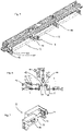
- figure 8 shows a representation of a part of the sorting device, in particular one of the rotatable rollers 22.
- This rotatable roller can be shifted laterally by means of an adjustment unit 28, ie perpendicular to its direction of rotation.
- the reference number 14 designates in turn, a rotatable shaft that is responsible for this adjustment.
- the reference number 34 designates a connecting element with which sections of this shaft can be connected to one another.
- the reference number 30 designates in its entirety the actuating element with which the roller 22 can be displaced.
- the roller 22 can be arranged on a carriage, which in turn is arranged such that it can be displaced relative to a carrier, for example in the horizontal direction.
- a spindle drive (not shown in detail) can also be provided here again, which effects this adjustment.
- the reference number 35 designates an actuating element, such as a rotatable wheel, with which the adjustment can be effected centrally.
- this actuating element 35 can act, for example, both on the carrier or the element 30 and, for example, on the carrier or the element 32 in order to enable a parallel displacement of the entire roller.
- figure 10 shows a representation of a device according to the invention for treating plastic preforms.
- the plastic preforms are first sorted and transported with the device 1 according to the invention.
- the reference number 19 designates a synchronization device, which spaces the plastic preforms and thus feeds them to a heating device 50 in this spaced-apart state.
- This heating device also has a transport device which transports the plastic preforms 10 and, in so doing, in particular transports them past heating elements 53 and 54 in order to heat them in this way.
- the heating device is followed by a further transport device 60, such as a transfer star wheel, which ultimately feeds the plastic preforms to a device for forming plastic preforms into plastic containers.
- Reference number 18 designates a temperature measuring device which determines an input temperature of the plastic preforms.
- the sorting device 2 has two rollers 22 and 24 which are arranged parallel to one another and between which the plastic preforms can be conveyed.
Landscapes
- Engineering & Computer Science (AREA)
- Manufacturing & Machinery (AREA)
- Mechanical Engineering (AREA)
- Blow-Moulding Or Thermoforming Of Plastics Or The Like (AREA)
- Processing And Handling Of Plastics And Other Materials For Molding In General (AREA)
Claims (10)
- Dispositif (1) pour transporter des préformes en matière plastique avec un système de tri (2), lequel est adapté pour et se destine à trier des préformes en matière plastique et lequel transporte les préformes en matière plastique (10) dans une direction de transport prédéfinie, et avec un système de transport (4) disposé après le système de tri (2) dans la direction de transport, dans lequel ledit système de transport (4) présente un premier rail de support (42) pour supporter les préformes en matière plastique (10) et un deuxième rail de support (44) pour supporter les préformes en matière plastique (10) et les préformes en matière plastique (10) peuvent être transportées entre ledit premier rail de support (42) et ledit deuxième rail de support (44), dans lequel lesdits rails de support (42, 44) s'étendent le long de la direction de transport, dans lequel le système de tri présente deux rouleaux (22, 26) espacés l'un par rapport à l'autre, entre lesquels les préformes en matière plastique (10) peuvent être guidées,dans lequel le dispositif (1) présente un mécanisme d'ajustement (8) pour ajuster au moins un premier espacement latéral entre lesdits rails de support (42, 44),caractérisé en ce queledit mécanisme d'ajustement présente plusieurs unités d'ajustement (82, 84, 86), lesquelles sont disposées les unes derrière les autres le long de la direction de transport, dans lequel lesdites unités d'ajustement (82, 84, 86) permettent respectivement un ajustement de l'espacement latéral et dans lequel lesdites unités d'ajustement (82, 84, 86) sont couplées mécaniquement entre elles de telle manière que les unités d'ajustement (82, 84, 86) peuvent être ajustées conjointement.
- Dispositif (1) selon la revendication 1,
caractérisé en ce que
les unités d'ajustement (82, 84, 86) sont couplées entre elles au moyen d'au moins un système de couplage mécanique. - Dispositif (1) selon la revendication précédente,
caractérisé en ce que
le système de couplage (12) présente au moins un corps de type tige pouvant tourner et/ou pouvant être coulissé le long de sa direction longitudinale. - Dispositif (1) selon au moins l'une quelconque des revendications précédentes,
caractérisé en ce que
le dispositif présente un système d'entraînement pour entraîner les unités d'ajustement. - Dispositif (1) selon au moins l'une quelconque des revendications précédentes,
caractérisé en ce que
le système de transport (4) présente un élément serre-flan (46), lequel s'étend au moins par endroits le long de la direction de transport (T) et lequel peut être ajusté de manière préférée également par le mécanisme d'ajustement. - Dispositif (1) selon au moins l'une quelconque des revendications précédentes,
caractérisé en ce que
le système de transport (4) présente des éléments de guidage (47, 48) pour guider les corps préformés. - Dispositif (1) selon la revendication précédente,
caractérisé en ce que
les éléments de guidage (47, 48) peuvent être ajustés également par le mécanisme d'ajustement. - Dispositif (1) selon au moins l'une quelconque des revendications précédentes,
caractérisé en ce que
un espacement entre les deux rouleaux (22, 24) du système de tri peut être ajusté également. - Dispositif (1) selon au moins l'une quelconque des revendications précédentes,
caractérisé en ce que
les rails de support (42, 44), les éléments de guidage (47, 48) et l'élément serre-flan (46) peuvent être ajustés individuellement. - Procédé pour transporter des préformes en matière plastique, dans lequel les préformes en matière plastique sont triées avec un système de tri (2) et sont transportées avec un système de transport (4) disposé après le système de tri (2) dans la direction de transport, dans lequel ledit système de transport (4) présente un premier rail de support (42) pour supporter les préformes en matière plastique (10) et un deuxième rail de support (44) pour supporter les préformes en matière plastique (10) et les préformes en matière plastique (10) sont transportées entre ledit premier rail de support (42) et ledit deuxième rail de support (44), dans lequel lesdits rails de support (42, 44) s'étendent le long de la direction de transport, dans lequel le système de tri présente deux rouleaux (22, 26) espacés l'un par rapport à l'autre, entre lesquels les préformes en matière plastique (10) sont transportées,dans lequel le dispositif (1) présente un mécanisme d'ajustement (8) pour ajuster au moins un espacement latéral desdits rails de support (42, 44),caractérisé en ce queledit mécanisme d'ajustement présente plusieurs unités d'ajustement (82, 84, 86), lesquelles sont disposées les unes derrière les autres le long de la direction de transport, dans lequel lesdites unités d'ajustement (82, 84, 86) permettent respectivement un ajustement de l'espacement latéral et dans lequel lesdites unités d'ajustement (82, 84, 86) sont couplées mécaniquement entre elles de telle manière que les unités d'ajustement (82, 84, 86) peuvent être ajustées conjointement.
Priority Applications (2)
| Application Number | Priority Date | Filing Date | Title |
|---|---|---|---|
| EP22193313.8A EP4119327B1 (fr) | 2018-07-11 | 2019-06-18 | Dispositif de tri et rail d'alimentation pour préformes en matière plastique |
| EP23196515.3A EP4269065A3 (fr) | 2018-07-11 | 2019-06-18 | Dispositif de tri et rail d'alimentation pour préformes en matière plastique |
Applications Claiming Priority (2)
| Application Number | Priority Date | Filing Date | Title |
|---|---|---|---|
| DE102018116841.1A DE102018116841A1 (de) | 2018-07-11 | 2018-07-11 | Sortiereinrichtung und Zuführschiene für Kunststoffvorformlinge |
| PCT/EP2019/066081 WO2020011497A1 (fr) | 2018-07-11 | 2019-06-18 | Dispositif de tri et rail d'alimentation pour préformes en matière plastique |
Related Child Applications (2)
| Application Number | Title | Priority Date | Filing Date |
|---|---|---|---|
| EP22193313.8A Division EP4119327B1 (fr) | 2018-07-11 | 2019-06-18 | Dispositif de tri et rail d'alimentation pour préformes en matière plastique |
| EP23196515.3A Division EP4269065A3 (fr) | 2018-07-11 | 2019-06-18 | Dispositif de tri et rail d'alimentation pour préformes en matière plastique |
Publications (2)
| Publication Number | Publication Date |
|---|---|
| EP3793802A1 EP3793802A1 (fr) | 2021-03-24 |
| EP3793802B1 true EP3793802B1 (fr) | 2022-09-28 |
Family
ID=66999827
Family Applications (3)
| Application Number | Title | Priority Date | Filing Date |
|---|---|---|---|
| EP22193313.8A Active EP4119327B1 (fr) | 2018-07-11 | 2019-06-18 | Dispositif de tri et rail d'alimentation pour préformes en matière plastique |
| EP23196515.3A Pending EP4269065A3 (fr) | 2018-07-11 | 2019-06-18 | Dispositif de tri et rail d'alimentation pour préformes en matière plastique |
| EP19732330.6A Active EP3793802B1 (fr) | 2018-07-11 | 2019-06-18 | Dispositif de tri et rail d'alimentation pour préformes en matière plastique |
Family Applications Before (2)
| Application Number | Title | Priority Date | Filing Date |
|---|---|---|---|
| EP22193313.8A Active EP4119327B1 (fr) | 2018-07-11 | 2019-06-18 | Dispositif de tri et rail d'alimentation pour préformes en matière plastique |
| EP23196515.3A Pending EP4269065A3 (fr) | 2018-07-11 | 2019-06-18 | Dispositif de tri et rail d'alimentation pour préformes en matière plastique |
Country Status (5)
| Country | Link |
|---|---|
| US (1) | US11712833B2 (fr) |
| EP (3) | EP4119327B1 (fr) |
| CN (1) | CN215750692U (fr) |
| DE (1) | DE102018116841A1 (fr) |
| WO (1) | WO2020011497A1 (fr) |
Families Citing this family (3)
| Publication number | Priority date | Publication date | Assignee | Title |
|---|---|---|---|---|
| DE102020106422A1 (de) * | 2020-03-10 | 2021-09-16 | Krones Aktiengesellschaft | Vorrichtung und Verfahren zum Behandeln von Kunststoffvorformlingen mit integrierter Vorformlingzuführung |
| DE102021122971A1 (de) | 2021-09-06 | 2023-03-09 | Khs Gmbh | Vorrichtung zur Herstellung von Behältern aus thermoplastisches Material aufweisenden Vorformlingen |
| DE102022123108A1 (de) | 2022-09-12 | 2024-03-14 | Khs Gmbh | Vereinzelungsvorrichtung sowie Verfahren zum Vereinzeln von Vorformlingen |
Citations (32)
| Publication number | Priority date | Publication date | Assignee | Title |
|---|---|---|---|---|
| EP0070931A1 (fr) | 1978-11-16 | 1983-02-09 | THE MOTCH & MERRYWEATHER MACHINERY COMPANY | Transporteur pneumatique pour éléments de bouteille |
| EP0526963A1 (fr) | 1991-08-06 | 1993-02-10 | Simplimatic Engineering Company | Convoyeur d'air pour bouteilles |
| US5246314A (en) | 1991-08-06 | 1993-09-21 | Simplimatic Engineering Company | Bottle air conveyor with adjustable guides |
| EP1012089A1 (fr) | 1997-09-12 | 2000-06-28 | Netra Systems | Convoyeur pneumatique pour articles, avec caisson de transport, permettant de minimiser le degre de contamination des articles, et procede de nettoyage d'un tel convoyeur |
| DE19915356A1 (de) | 1999-04-06 | 2000-10-12 | Gassner Gmbh | Sortier- und Beschickungsvorrichtung |
| WO2000068122A1 (fr) | 1999-05-06 | 2000-11-16 | Rafale Technologie | Dispositif de convoyage d'objets |
| FR2806395A1 (fr) | 2000-03-16 | 2001-09-21 | Netra Systems | Troncon courbe de convoyeur avec rails de guidage a ecartement reglable |
| EP1281503A1 (fr) | 2001-06-30 | 2003-02-05 | SIG Corpoplast GmbH & Co. KG | Dispositif de transport d'articles |
| US20030094352A1 (en) | 2001-11-02 | 2003-05-22 | Rexnord Marbett S.P.A. | Positioning system of conveyor guides |
| EP1335870A1 (fr) | 2000-11-03 | 2003-08-20 | Sidel S.A. | Systeme d'alimentation de preformes destine notamment a une machine de soufflage de recipients |
| JP2003276840A (ja) | 2002-03-25 | 2003-10-02 | Rse:Kk | エアーコンベアのガイド間隔自動調整装置 |
| WO2006058511A1 (fr) | 2004-11-30 | 2006-06-08 | Sig Technology Ltd. | Procede et dispositif pour le transport d'ebauches |
| FR2880877A1 (fr) | 2005-01-20 | 2006-07-21 | Netra Systems Sa | Convoyeur a air pour articles suspendus avec poutre porteuse pour accessoires de convoyage |
| US20060163043A1 (en) | 2003-02-18 | 2006-07-27 | Sidel (Canada) Inc. | Actuating assembly for an adjustable width guideway in a conveyor system for bottles |
| FR2886205A1 (fr) | 2005-05-24 | 2006-12-01 | Sidel Sas | Element de rail de convoyage d'objets en position suspendue et dispositif d'alimentation comprenant un tel element |
| US20080149465A1 (en) | 2006-12-20 | 2008-06-26 | Krones Ag | Pneumatic conveyor for containers |
| US20080156621A1 (en) | 2004-06-01 | 2008-07-03 | Hakon Lundberg | Arrangement And Method For Adjustment Of Rail At A Conveyor |
| US7530453B2 (en) | 2006-10-30 | 2009-05-12 | Advanced Manufacturing Technology | Adjustable neck guide |
| FR2932466A1 (fr) | 2008-06-13 | 2009-12-18 | Sidel Participations | Installation de convoyage multivoies |
| DE102009016593A1 (de) | 2009-04-08 | 2010-10-14 | Krones Ag | Vorrichtung zum Transport von Vorformlingen |
| US20110061347A1 (en) | 2009-09-11 | 2011-03-17 | Christian Stoiber | Container treatment plant and a container treatment method for the treatment of containers capable of being filled with a product |
| US20110079493A1 (en) | 2009-10-02 | 2011-04-07 | Bell Glen A | Guide rail system |
| US20120103763A1 (en) | 2010-10-29 | 2012-05-03 | Bell Glen A | Guide rail system |
| US20130156512A1 (en) | 2011-12-14 | 2013-06-20 | Krones Ag | Apparatus for the conveying of plastics material preforms |
| US8852492B2 (en) | 2011-08-22 | 2014-10-07 | Krones Ag | Heating device and heating method for blow molding machine as well as blow molding machine |
| US20150008099A1 (en) | 2013-07-04 | 2015-01-08 | Krones Aktiengesellschaft | Transport section of a horizontal conveyor device with at least one adjustable guide element |
| WO2015071827A1 (fr) | 2013-11-12 | 2015-05-21 | Bett Sistemi S.R.L. | Appareil de transport de produits |
| WO2016005673A1 (fr) | 2014-07-11 | 2016-01-14 | Sidel Participations | Dispositif d'alimentation de préformes comportant une glissière de défilement équipée de butées latérales pour arrêter des préformes couchées |
| US9375878B2 (en) | 2010-08-03 | 2016-06-28 | Krones Ag | Method and apparatus for operating a plant for the treatment of containers with superordinated choice of parameters |
| US20160339622A1 (en) | 2015-05-19 | 2016-11-24 | Krones Ag | Apparatus and a method for heating plastic preforms with decoupled transport devices |
| WO2018029283A1 (fr) | 2016-08-09 | 2018-02-15 | Krones Ag | Dispositif de chauffage de préformes au moyen d'un émetteur supérieur transporté |
| WO2019048182A1 (fr) | 2017-09-06 | 2019-03-14 | Sidel Participations | Procede et dispositif de reglage d'un convoyeur de preformes |
Family Cites Families (3)
| Publication number | Priority date | Publication date | Assignee | Title |
|---|---|---|---|---|
| WO2004074142A1 (fr) * | 2003-02-18 | 2004-09-02 | Sidel (Canada) Inc. | Piste de guidage courbe reglable pour convoyeur, et son procede de realisation |
| DE20308513U1 (de) | 2003-05-30 | 2004-07-08 | Krones Ag | Vorrichtung zum Zuführen von Vorformlingen zu einer Blasmaschine |
| DE102005048358A1 (de) * | 2004-11-30 | 2006-08-24 | Sig Technology Ltd. | Verfahren und Vorrichtung zum Transport von Vorformlingen |
-
2018
- 2018-07-11 DE DE102018116841.1A patent/DE102018116841A1/de active Pending
-
2019
- 2019-06-18 US US17/253,003 patent/US11712833B2/en active Active
- 2019-06-18 EP EP22193313.8A patent/EP4119327B1/fr active Active
- 2019-06-18 CN CN201990000785.9U patent/CN215750692U/zh active Active
- 2019-06-18 WO PCT/EP2019/066081 patent/WO2020011497A1/fr unknown
- 2019-06-18 EP EP23196515.3A patent/EP4269065A3/fr active Pending
- 2019-06-18 EP EP19732330.6A patent/EP3793802B1/fr active Active
Patent Citations (33)
| Publication number | Priority date | Publication date | Assignee | Title |
|---|---|---|---|---|
| EP0070931A1 (fr) | 1978-11-16 | 1983-02-09 | THE MOTCH & MERRYWEATHER MACHINERY COMPANY | Transporteur pneumatique pour éléments de bouteille |
| EP0526963A1 (fr) | 1991-08-06 | 1993-02-10 | Simplimatic Engineering Company | Convoyeur d'air pour bouteilles |
| US5246314A (en) | 1991-08-06 | 1993-09-21 | Simplimatic Engineering Company | Bottle air conveyor with adjustable guides |
| EP1012089A1 (fr) | 1997-09-12 | 2000-06-28 | Netra Systems | Convoyeur pneumatique pour articles, avec caisson de transport, permettant de minimiser le degre de contamination des articles, et procede de nettoyage d'un tel convoyeur |
| DE19915356A1 (de) | 1999-04-06 | 2000-10-12 | Gassner Gmbh | Sortier- und Beschickungsvorrichtung |
| WO2000068122A1 (fr) | 1999-05-06 | 2000-11-16 | Rafale Technologie | Dispositif de convoyage d'objets |
| FR2806395A1 (fr) | 2000-03-16 | 2001-09-21 | Netra Systems | Troncon courbe de convoyeur avec rails de guidage a ecartement reglable |
| EP1335870A1 (fr) | 2000-11-03 | 2003-08-20 | Sidel S.A. | Systeme d'alimentation de preformes destine notamment a une machine de soufflage de recipients |
| EP1281503A1 (fr) | 2001-06-30 | 2003-02-05 | SIG Corpoplast GmbH & Co. KG | Dispositif de transport d'articles |
| US20030094352A1 (en) | 2001-11-02 | 2003-05-22 | Rexnord Marbett S.P.A. | Positioning system of conveyor guides |
| JP2003276840A (ja) | 2002-03-25 | 2003-10-02 | Rse:Kk | エアーコンベアのガイド間隔自動調整装置 |
| US20060163043A1 (en) | 2003-02-18 | 2006-07-27 | Sidel (Canada) Inc. | Actuating assembly for an adjustable width guideway in a conveyor system for bottles |
| US20080156621A1 (en) | 2004-06-01 | 2008-07-03 | Hakon Lundberg | Arrangement And Method For Adjustment Of Rail At A Conveyor |
| WO2006058511A1 (fr) | 2004-11-30 | 2006-06-08 | Sig Technology Ltd. | Procede et dispositif pour le transport d'ebauches |
| FR2880877A1 (fr) | 2005-01-20 | 2006-07-21 | Netra Systems Sa | Convoyeur a air pour articles suspendus avec poutre porteuse pour accessoires de convoyage |
| FR2886205A1 (fr) | 2005-05-24 | 2006-12-01 | Sidel Sas | Element de rail de convoyage d'objets en position suspendue et dispositif d'alimentation comprenant un tel element |
| US20080196998A1 (en) | 2005-05-24 | 2008-08-21 | Sidel Participations | Rail Element For Conveying Suspended Objects, Preform-Supply Device Comprising One Such Element And Curved Flat Band Which Can Be Fixed To One Such Element |
| US7530453B2 (en) | 2006-10-30 | 2009-05-12 | Advanced Manufacturing Technology | Adjustable neck guide |
| US20080149465A1 (en) | 2006-12-20 | 2008-06-26 | Krones Ag | Pneumatic conveyor for containers |
| FR2932466A1 (fr) | 2008-06-13 | 2009-12-18 | Sidel Participations | Installation de convoyage multivoies |
| DE102009016593A1 (de) | 2009-04-08 | 2010-10-14 | Krones Ag | Vorrichtung zum Transport von Vorformlingen |
| US20110061347A1 (en) | 2009-09-11 | 2011-03-17 | Christian Stoiber | Container treatment plant and a container treatment method for the treatment of containers capable of being filled with a product |
| US20110079493A1 (en) | 2009-10-02 | 2011-04-07 | Bell Glen A | Guide rail system |
| US9375878B2 (en) | 2010-08-03 | 2016-06-28 | Krones Ag | Method and apparatus for operating a plant for the treatment of containers with superordinated choice of parameters |
| US20120103763A1 (en) | 2010-10-29 | 2012-05-03 | Bell Glen A | Guide rail system |
| US8852492B2 (en) | 2011-08-22 | 2014-10-07 | Krones Ag | Heating device and heating method for blow molding machine as well as blow molding machine |
| US20130156512A1 (en) | 2011-12-14 | 2013-06-20 | Krones Ag | Apparatus for the conveying of plastics material preforms |
| US20150008099A1 (en) | 2013-07-04 | 2015-01-08 | Krones Aktiengesellschaft | Transport section of a horizontal conveyor device with at least one adjustable guide element |
| WO2015071827A1 (fr) | 2013-11-12 | 2015-05-21 | Bett Sistemi S.R.L. | Appareil de transport de produits |
| WO2016005673A1 (fr) | 2014-07-11 | 2016-01-14 | Sidel Participations | Dispositif d'alimentation de préformes comportant une glissière de défilement équipée de butées latérales pour arrêter des préformes couchées |
| US20160339622A1 (en) | 2015-05-19 | 2016-11-24 | Krones Ag | Apparatus and a method for heating plastic preforms with decoupled transport devices |
| WO2018029283A1 (fr) | 2016-08-09 | 2018-02-15 | Krones Ag | Dispositif de chauffage de préformes au moyen d'un émetteur supérieur transporté |
| WO2019048182A1 (fr) | 2017-09-06 | 2019-03-14 | Sidel Participations | Procede et dispositif de reglage d'un convoyeur de preformes |
Also Published As
| Publication number | Publication date |
|---|---|
| CN215750692U (zh) | 2022-02-08 |
| EP3793802A1 (fr) | 2021-03-24 |
| EP4119327A1 (fr) | 2023-01-18 |
| WO2020011497A1 (fr) | 2020-01-16 |
| US11712833B2 (en) | 2023-08-01 |
| US20210114279A1 (en) | 2021-04-22 |
| DE102018116841A1 (de) | 2020-01-16 |
| EP4119327B1 (fr) | 2023-12-20 |
| EP4269065A2 (fr) | 2023-11-01 |
| EP4269065A3 (fr) | 2023-12-27 |
Similar Documents
| Publication | Publication Date | Title |
|---|---|---|
| EP3793802B1 (fr) | Dispositif de tri et rail d'alimentation pour préformes en matière plastique | |
| DE69008256T2 (de) | Vorrichtung zum Rillen und Schneiden endloser Bahnen aus Pappe und dergleichen. | |
| EP3676186B1 (fr) | Dispositif à porte-plaque à changement rapide et came de guidage coulissante | |
| EP3268144A1 (fr) | Machine à dresser et procédé de remplacement d'éléments de roulement à dresser | |
| DE69311447T2 (de) | Verfahren zum kontinuierlichen Herstellen von gewelltem Bahnenmaterial | |
| EP2604411A1 (fr) | Dispositif pour transporter des préformes en plastique | |
| EP2923852B1 (fr) | Dispositif de formage de couvertures de livre | |
| EP0665722A1 (fr) | Procede et dispositif pour convoyer des pieces planes | |
| WO2018108340A1 (fr) | Procédé et dispositif d'assemblage de pièces à usiner comportant au moins deux dispositifs de transport commandables indépendamment l'un de l'autre destinés au réglage d'un écart entre les extrémités côté tête et/ou les extrémités côté arrière des pièces à usiner avant l'assemblage | |
| EP0901848B1 (fr) | Presse de transfert avec changement d' outil automatique | |
| EP2208680A1 (fr) | Dispositif de traitement d'objets plats alimentés en continu les uns derrière les autres ou d'une bande de matériau quasi-infinie | |
| DE10122377C1 (de) | Vorrichtung zur Rückführung von Werkstücken | |
| WO2020011498A1 (fr) | Dispositif de tri et rail d'alimentation pour préformes en matière plastique | |
| DE102006035648A1 (de) | Vorrichtung zum Herstellen oder/und Bearbeiten von Paneelen | |
| DE10162282A1 (de) | Transfereinrichtung zum Transport von Formteilen | |
| DE102015121884A1 (de) | Transportvorrichtung zum Transport eines Werkstückes entlang aufeinanderfolgender Bearbeitungsstationen einer Produktionseinrichtung, Produktionseinrichtung, mehrstufige Umformpresse und Verfahren zum Fertigen von Produkten aus Werkstücken mittels einer Produktionseinrichtung | |
| EP0742061B1 (fr) | Dispositif d'enroulement réglé électroniquement pour la fabrication de ressorts pour des matelas ou rembourrages | |
| EP0439680A2 (fr) | Procédé et dispositif pour transporter des objets le long d'une ligne de production | |
| EP3369663B1 (fr) | Dispositif de bottelage pour pièces à usiner oblongues ainsi que procédé de bottelage de pièces à usiner oblongues | |
| DE60309133T2 (de) | Vorrichtung zur anpassung des abstandes zwischen förderfingern an die länge des produktes | |
| WO2020011496A1 (fr) | Dispositif et procédé pour transporter des contenants et en particulier des préformes en matière plastique | |
| EP4067049A1 (fr) | Dispositif de formage de préformes en matière plastique en des récipients en matière plastique pourvu d'entraînements découplés | |
| DE102022120537B3 (de) | Kuppelvorrichtung und Rollformanlage | |
| DE102018102417A1 (de) | Vorrichtung zum Transportieren und Ausrichten von einem oder mehreren flächigen Bauteilen | |
| EP3369685A1 (fr) | Dispositif de transport de pièces allongées à un point de réception et de dépôt des dites pièces allongées audit point de réception |
Legal Events
| Date | Code | Title | Description |
|---|---|---|---|
| STAA | Information on the status of an ep patent application or granted ep patent |
Free format text: STATUS: UNKNOWN |
|
| STAA | Information on the status of an ep patent application or granted ep patent |
Free format text: STATUS: THE INTERNATIONAL PUBLICATION HAS BEEN MADE |
|
| STAA | Information on the status of an ep patent application or granted ep patent |
Free format text: STATUS: THE INTERNATIONAL PUBLICATION HAS BEEN MADE |
|
| PUAI | Public reference made under article 153(3) epc to a published international application that has entered the european phase |
Free format text: ORIGINAL CODE: 0009012 |
|
| STAA | Information on the status of an ep patent application or granted ep patent |
Free format text: STATUS: REQUEST FOR EXAMINATION WAS MADE |
|
| 17P | Request for examination filed |
Effective date: 20201214 |
|
| AK | Designated contracting states |
Kind code of ref document: A1 Designated state(s): AL AT BE BG CH CY CZ DE DK EE ES FI FR GB GR HR HU IE IS IT LI LT LU LV MC MK MT NL NO PL PT RO RS SE SI SK SM TR |
|
| AX | Request for extension of the european patent |
Extension state: BA ME |
|
| DAV | Request for validation of the european patent (deleted) | ||
| DAX | Request for extension of the european patent (deleted) | ||
| GRAP | Despatch of communication of intention to grant a patent |
Free format text: ORIGINAL CODE: EPIDOSNIGR1 |
|
| STAA | Information on the status of an ep patent application or granted ep patent |
Free format text: STATUS: GRANT OF PATENT IS INTENDED |
|
| INTG | Intention to grant announced |
Effective date: 20220506 |
|
| GRAS | Grant fee paid |
Free format text: ORIGINAL CODE: EPIDOSNIGR3 |
|
| GRAA | (expected) grant |
Free format text: ORIGINAL CODE: 0009210 |
|
| STAA | Information on the status of an ep patent application or granted ep patent |
Free format text: STATUS: THE PATENT HAS BEEN GRANTED |
|
| AK | Designated contracting states |
Kind code of ref document: B1 Designated state(s): AL AT BE BG CH CY CZ DE DK EE ES FI FR GB GR HR HU IE IS IT LI LT LU LV MC MK MT NL NO PL PT RO RS SE SI SK SM TR |
|
| REG | Reference to a national code |
Ref country code: GB Ref legal event code: FG4D Free format text: NOT ENGLISH |
|
| REG | Reference to a national code |
Ref country code: CH Ref legal event code: EP |
|
| REG | Reference to a national code |
Ref country code: AT Ref legal event code: REF Ref document number: 1520972 Country of ref document: AT Kind code of ref document: T Effective date: 20221015 |
|
| REG | Reference to a national code |
Ref country code: DE Ref legal event code: R096 Ref document number: 502019005770 Country of ref document: DE |
|
| REG | Reference to a national code |
Ref country code: IE Ref legal event code: FG4D Free format text: LANGUAGE OF EP DOCUMENT: GERMAN |
|
| REG | Reference to a national code |
Ref country code: LT Ref legal event code: MG9D |
|
| PG25 | Lapsed in a contracting state [announced via postgrant information from national office to epo] |
Ref country code: SE Free format text: LAPSE BECAUSE OF FAILURE TO SUBMIT A TRANSLATION OF THE DESCRIPTION OR TO PAY THE FEE WITHIN THE PRESCRIBED TIME-LIMIT Effective date: 20220928 Ref country code: RS Free format text: LAPSE BECAUSE OF FAILURE TO SUBMIT A TRANSLATION OF THE DESCRIPTION OR TO PAY THE FEE WITHIN THE PRESCRIBED TIME-LIMIT Effective date: 20220928 Ref country code: NO Free format text: LAPSE BECAUSE OF FAILURE TO SUBMIT A TRANSLATION OF THE DESCRIPTION OR TO PAY THE FEE WITHIN THE PRESCRIBED TIME-LIMIT Effective date: 20221228 Ref country code: LV Free format text: LAPSE BECAUSE OF FAILURE TO SUBMIT A TRANSLATION OF THE DESCRIPTION OR TO PAY THE FEE WITHIN THE PRESCRIBED TIME-LIMIT Effective date: 20220928 Ref country code: LT Free format text: LAPSE BECAUSE OF FAILURE TO SUBMIT A TRANSLATION OF THE DESCRIPTION OR TO PAY THE FEE WITHIN THE PRESCRIBED TIME-LIMIT Effective date: 20220928 Ref country code: FI Free format text: LAPSE BECAUSE OF FAILURE TO SUBMIT A TRANSLATION OF THE DESCRIPTION OR TO PAY THE FEE WITHIN THE PRESCRIBED TIME-LIMIT Effective date: 20220928 |
|
| REG | Reference to a national code |
Ref country code: NL Ref legal event code: MP Effective date: 20220928 |
|
| PG25 | Lapsed in a contracting state [announced via postgrant information from national office to epo] |
Ref country code: HR Free format text: LAPSE BECAUSE OF FAILURE TO SUBMIT A TRANSLATION OF THE DESCRIPTION OR TO PAY THE FEE WITHIN THE PRESCRIBED TIME-LIMIT Effective date: 20220928 Ref country code: GR Free format text: LAPSE BECAUSE OF FAILURE TO SUBMIT A TRANSLATION OF THE DESCRIPTION OR TO PAY THE FEE WITHIN THE PRESCRIBED TIME-LIMIT Effective date: 20221229 |
|
| PG25 | Lapsed in a contracting state [announced via postgrant information from national office to epo] |
Ref country code: SM Free format text: LAPSE BECAUSE OF FAILURE TO SUBMIT A TRANSLATION OF THE DESCRIPTION OR TO PAY THE FEE WITHIN THE PRESCRIBED TIME-LIMIT Effective date: 20220928 Ref country code: RO Free format text: LAPSE BECAUSE OF FAILURE TO SUBMIT A TRANSLATION OF THE DESCRIPTION OR TO PAY THE FEE WITHIN THE PRESCRIBED TIME-LIMIT Effective date: 20220928 Ref country code: PT Free format text: LAPSE BECAUSE OF FAILURE TO SUBMIT A TRANSLATION OF THE DESCRIPTION OR TO PAY THE FEE WITHIN THE PRESCRIBED TIME-LIMIT Effective date: 20230130 Ref country code: ES Free format text: LAPSE BECAUSE OF FAILURE TO SUBMIT A TRANSLATION OF THE DESCRIPTION OR TO PAY THE FEE WITHIN THE PRESCRIBED TIME-LIMIT Effective date: 20220928 Ref country code: CZ Free format text: LAPSE BECAUSE OF FAILURE TO SUBMIT A TRANSLATION OF THE DESCRIPTION OR TO PAY THE FEE WITHIN THE PRESCRIBED TIME-LIMIT Effective date: 20220928 |
|
| PG25 | Lapsed in a contracting state [announced via postgrant information from national office to epo] |
Ref country code: SK Free format text: LAPSE BECAUSE OF FAILURE TO SUBMIT A TRANSLATION OF THE DESCRIPTION OR TO PAY THE FEE WITHIN THE PRESCRIBED TIME-LIMIT Effective date: 20220928 Ref country code: PL Free format text: LAPSE BECAUSE OF FAILURE TO SUBMIT A TRANSLATION OF THE DESCRIPTION OR TO PAY THE FEE WITHIN THE PRESCRIBED TIME-LIMIT Effective date: 20220928 Ref country code: IS Free format text: LAPSE BECAUSE OF FAILURE TO SUBMIT A TRANSLATION OF THE DESCRIPTION OR TO PAY THE FEE WITHIN THE PRESCRIBED TIME-LIMIT Effective date: 20230128 Ref country code: EE Free format text: LAPSE BECAUSE OF FAILURE TO SUBMIT A TRANSLATION OF THE DESCRIPTION OR TO PAY THE FEE WITHIN THE PRESCRIBED TIME-LIMIT Effective date: 20220928 |
|
| P01 | Opt-out of the competence of the unified patent court (upc) registered |
Effective date: 20230523 |
|
| REG | Reference to a national code |
Ref country code: DE Ref legal event code: R026 Ref document number: 502019005770 Country of ref document: DE |
|
| PG25 | Lapsed in a contracting state [announced via postgrant information from national office to epo] |
Ref country code: NL Free format text: LAPSE BECAUSE OF FAILURE TO SUBMIT A TRANSLATION OF THE DESCRIPTION OR TO PAY THE FEE WITHIN THE PRESCRIBED TIME-LIMIT Effective date: 20220928 Ref country code: AL Free format text: LAPSE BECAUSE OF FAILURE TO SUBMIT A TRANSLATION OF THE DESCRIPTION OR TO PAY THE FEE WITHIN THE PRESCRIBED TIME-LIMIT Effective date: 20220928 |
|
| PLBI | Opposition filed |
Free format text: ORIGINAL CODE: 0009260 |
|
| PLAB | Opposition data, opponent's data or that of the opponent's representative modified |
Free format text: ORIGINAL CODE: 0009299OPPO |
|
| PLAX | Notice of opposition and request to file observation + time limit sent |
Free format text: ORIGINAL CODE: EPIDOSNOBS2 |
|
| PG25 | Lapsed in a contracting state [announced via postgrant information from national office to epo] |
Ref country code: DK Free format text: LAPSE BECAUSE OF FAILURE TO SUBMIT A TRANSLATION OF THE DESCRIPTION OR TO PAY THE FEE WITHIN THE PRESCRIBED TIME-LIMIT Effective date: 20220928 |
|
| 26 | Opposition filed |
Opponent name: SIDEL PARTICIPATIONS Effective date: 20230628 |
|
| R26 | Opposition filed (corrected) |
Opponent name: SIDEL PARTICIPATIONS Effective date: 20230628 |
|
| PGFP | Annual fee paid to national office [announced via postgrant information from national office to epo] |
Ref country code: CH Payment date: 20230702 Year of fee payment: 5 |
|
| PLAF | Information modified related to communication of a notice of opposition and request to file observations + time limit |
Free format text: ORIGINAL CODE: EPIDOSCOBS2 |
|
| PG25 | Lapsed in a contracting state [announced via postgrant information from national office to epo] |
Ref country code: SI Free format text: LAPSE BECAUSE OF FAILURE TO SUBMIT A TRANSLATION OF THE DESCRIPTION OR TO PAY THE FEE WITHIN THE PRESCRIBED TIME-LIMIT Effective date: 20220928 |
|
| PG25 | Lapsed in a contracting state [announced via postgrant information from national office to epo] |
Ref country code: MC Free format text: LAPSE BECAUSE OF FAILURE TO SUBMIT A TRANSLATION OF THE DESCRIPTION OR TO PAY THE FEE WITHIN THE PRESCRIBED TIME-LIMIT Effective date: 20220928 |
|
| PLBB | Reply of patent proprietor to notice(s) of opposition received |
Free format text: ORIGINAL CODE: EPIDOSNOBS3 |
|
| PG25 | Lapsed in a contracting state [announced via postgrant information from national office to epo] |
Ref country code: MC Free format text: LAPSE BECAUSE OF FAILURE TO SUBMIT A TRANSLATION OF THE DESCRIPTION OR TO PAY THE FEE WITHIN THE PRESCRIBED TIME-LIMIT Effective date: 20220928 |
|
| REG | Reference to a national code |
Ref country code: BE Ref legal event code: MM Effective date: 20230630 |
|
| GBPC | Gb: european patent ceased through non-payment of renewal fee |
Effective date: 20230618 |
|
| PG25 | Lapsed in a contracting state [announced via postgrant information from national office to epo] |
Ref country code: LU Free format text: LAPSE BECAUSE OF NON-PAYMENT OF DUE FEES Effective date: 20230618 |
|
| REG | Reference to a national code |
Ref country code: IE Ref legal event code: MM4A |
|
| PG25 | Lapsed in a contracting state [announced via postgrant information from national office to epo] |
Ref country code: LU Free format text: LAPSE BECAUSE OF NON-PAYMENT OF DUE FEES Effective date: 20230618 |
|
| PG25 | Lapsed in a contracting state [announced via postgrant information from national office to epo] |
Ref country code: IE Free format text: LAPSE BECAUSE OF NON-PAYMENT OF DUE FEES Effective date: 20230618 |
|
| PG25 | Lapsed in a contracting state [announced via postgrant information from national office to epo] |
Ref country code: IE Free format text: LAPSE BECAUSE OF NON-PAYMENT OF DUE FEES Effective date: 20230618 Ref country code: GB Free format text: LAPSE BECAUSE OF NON-PAYMENT OF DUE FEES Effective date: 20230618 |
|
| PG25 | Lapsed in a contracting state [announced via postgrant information from national office to epo] |
Ref country code: BE Free format text: LAPSE BECAUSE OF NON-PAYMENT OF DUE FEES Effective date: 20230630 |
|
| PGFP | Annual fee paid to national office [announced via postgrant information from national office to epo] |
Ref country code: DE Payment date: 20240502 Year of fee payment: 6 |
|
| PGFP | Annual fee paid to national office [announced via postgrant information from national office to epo] |
Ref country code: IT Payment date: 20240513 Year of fee payment: 6 Ref country code: FR Payment date: 20240509 Year of fee payment: 6 |