EP3792011A1 - Robotersteuerungsverfahren - Google Patents
Robotersteuerungsverfahren Download PDFInfo
- Publication number
- EP3792011A1 EP3792011A1 EP19800374.1A EP19800374A EP3792011A1 EP 3792011 A1 EP3792011 A1 EP 3792011A1 EP 19800374 A EP19800374 A EP 19800374A EP 3792011 A1 EP3792011 A1 EP 3792011A1
- Authority
- EP
- European Patent Office
- Prior art keywords
- collision
- arm
- robot
- operation program
- load information
- Prior art date
- Legal status (The legal status is an assumption and is not a legal conclusion. Google has not performed a legal analysis and makes no representation as to the accuracy of the status listed.)
- Pending
Links
Images


Classifications
-
- B—PERFORMING OPERATIONS; TRANSPORTING
- B25—HAND TOOLS; PORTABLE POWER-DRIVEN TOOLS; MANIPULATORS
- B25J—MANIPULATORS; CHAMBERS PROVIDED WITH MANIPULATION DEVICES
- B25J9/00—Program-controlled manipulators
- B25J9/16—Program controls
- B25J9/1656—Program controls characterised by programming, planning systems for manipulators
- B25J9/1664—Program controls characterised by programming, planning systems for manipulators characterised by motion, path, trajectory planning
- B25J9/1666—Avoiding collision or forbidden zones
-
- B—PERFORMING OPERATIONS; TRANSPORTING
- B25—HAND TOOLS; PORTABLE POWER-DRIVEN TOOLS; MANIPULATORS
- B25J—MANIPULATORS; CHAMBERS PROVIDED WITH MANIPULATION DEVICES
- B25J9/00—Program-controlled manipulators
- B25J9/16—Program controls
- B25J9/1628—Program controls characterised by the control loop
- B25J9/1638—Program controls characterised by the control loop compensation for arm bending/inertia, pay load weight/inertia
-
- B—PERFORMING OPERATIONS; TRANSPORTING
- B25—HAND TOOLS; PORTABLE POWER-DRIVEN TOOLS; MANIPULATORS
- B25J—MANIPULATORS; CHAMBERS PROVIDED WITH MANIPULATION DEVICES
- B25J9/00—Program-controlled manipulators
- B25J9/16—Program controls
- B25J9/1602—Program controls characterised by the control system, structure, architecture
-
- B—PERFORMING OPERATIONS; TRANSPORTING
- B25—HAND TOOLS; PORTABLE POWER-DRIVEN TOOLS; MANIPULATORS
- B25J—MANIPULATORS; CHAMBERS PROVIDED WITH MANIPULATION DEVICES
- B25J9/00—Program-controlled manipulators
- B25J9/16—Program controls
- B25J9/1674—Program controls characterised by safety, monitoring, diagnostic
-
- G—PHYSICS
- G05—CONTROLLING; REGULATING
- G05B—CONTROL OR REGULATING SYSTEMS IN GENERAL; FUNCTIONAL ELEMENTS OF SUCH SYSTEMS; MONITORING OR TESTING ARRANGEMENTS FOR SUCH SYSTEMS OR ELEMENTS
- G05B2219/00—Program-control systems
- G05B2219/30—Nc systems
- G05B2219/39—Robotics, robotics to robotics hand
- G05B2219/39176—Compensation deflection arm
Definitions
- the present invention relates to a robot control method.
- a robot control method has been known to date, in which each joint portion of a robot is driven in accordance with teaching data (see, for example, Patent Documents 1 and 2). Since such a robot is driven using a speed reducer provided in the joint portion, the speed reducer and a bearing are elastically deformed and an arm is deflected. Accordingly, it is difficult to ensure absolute position accuracy.
- Patent Document 1 discloses calculating a deflection amount due to gravity at representative points, the number of which is at least one or more, on a response trajectory between two teaching points and performing deflection correction so that the response trajectory agrees with a command trajectory.
- Patent Document 2 discloses determining change in load torque from the load torque of each axis of the robot before a grip of a workpiece and the load torque of each axis in the state of gripping the workpiece, and correcting the deflection caused by the grip of the workpiece by manual operation.
- aspects of the present disclosure are directed to a robot control method for operating an arm of a robot including a plurality of joint portions in accordance with a predetermined operation program, and solutions described below are adopted.
- the method includes: inputting load information on a load to be attached to the arm and collision sensitivity indicating a threshold value for detection of a collision of the arm; calculating gravitational torque to be applied to the joint portion based on the load information; calculating a deflection amount of the arm based on the gravitational torque; calculating a correction amount for correcting the deflection amount based on the collision sensitivity; and correcting the deflection amount based on the correction amount.
- the gravitational torque is calculated based on the load information input, and the deflection amount of the arm is calculated based on the gravitational torque.
- the correction amount is calculated based on the collision sensitivity input, and the deflection amount is corrected.
- the collision sensitivity is high, a collision is detected quick. It may therefore be possible to consider that the information on the load attached to the arm is accurate. On the other hand, if the collision sensitivity is low, a collision is detected too late. Thus, the information on the load attached to the arm is unreliable.
- the deflection correction amount may be set to be larger as the collision sensitivity increases.
- the load information may be considered to be accurate, and the deflection correction amount may be calculated in consideration of the deflection amount caused by the load and the deflection amount due to the mass of the arm.
- the deflection correction amount may be calculated solely in consideration of the deflection amount due to the mass of the arm.
- the deflection correction amount may be calculated so as to gradually increase as the collision sensitivity increases in consideration of the deflection amount caused by the load and the deflection amount due to the mass of the arm.
- a second aspect is an embodiment of the first aspect.
- the calculating the deflection amount is executed in real time during movement of the robot.
- the deflection amount is calculated in real time while the robot moves. It is therefore possible to calculate the deflection amount accurately in consideration of the position information on the robot that is moving, the posture of the arm, and the like.
- a third aspect is an embodiment of the first or second aspect.
- the load information set in advance and the load information newly input are compared. If the difference therebetween is large, the operation program is modified.
- the deflection amount of the arm is larger than the amount that has been assumed.
- the operation program is modified so that the arm operates with a suitable correction amount in accordance with the new load. It is therefore possible to correct the deflection amount of the arm suitably and move the arm along the target travel path.
- a fourth aspect is an embodiment of any one of the first to third aspects.
- the collision sensitivity set in advance and the collision sensitivity newly input are compared. If the difference therebetween is large, the operation program is modified.
- the collision sensitivity set at the time of creation of the operation program is 80% and the collision sensitivity newly input is 20%, a collision is detected too late, and the information on the load attached to the arm is unreliable.
- the operation program is modified so that the arm operates with a suitable correction amount in accordance with the new collision sensitivity.
- a fifth aspect is an embodiment of any one of the first to fourth aspects.
- the calculating the deflection amount, the calculating the correction amount, and the correcting the deflection amount are each executed at a plurality of interpolation points on a travel path of the robot.
- the calculation of the deflection amount, the calculation of the correction amount, and the correction of the deflection amount are each executed at a plurality of interpolation points on the travel path of the robot.
- interpolation points as used herein each denote a target position in each control period while the arm moves between teaching points, i.e., target positions of the robot which are programmed.
- the deflection amount of the arm can be corrected suitably.
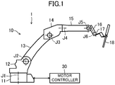
- a robot 1 includes a six-axis articulated robot arm 10.
- a motor controller 30, which controls the operation of the robot arm 10, is connected to the robot 1.
- the robot arm 10 includes: a base portion 11; a shoulder portion 12 supported by the base portion 11 so as to be turnable in a horizontal direction about a first joint portion J1; a lower arm portion 13 supported by the shoulder portion 12 so as to be turnable in an upward and downward direction about a second joint portion J2; a first upper arm portion 14 supported by the lower arm portion 13 so as to be turnable in an upward and downward direction about a third joint portion J3; a second upper arm portion 15 supported on the distal end of the first upper arm portion 14 so as to be twistable and rotatable about a fourth joint portion J4; a wrist portion 16 supported by the second upper arm portion 15 so as to be turnable in an the upward and downward direction about a fifth joint portion J5; and an attachment portion 17 supported by the wrist portion 16 so as to be twistable and rotatable about a sixth joint portion J6.
- a tool 18 (a welding torch in FIG. 1 ) as a load is attached to the attachment portion 17.
- a motor 21 (see FIG. 2 ) is built in each of the first to sixth joint portions J1 to J6.
- the motor controller 30 controls the driving of the motors 21 of the first to sixth joint portions J1 to J6 in accordance with an operation program input in advance through teaching or the like so that the first to sixth joint portions J1 to J6 reach respective target positions (command angles).
- the robot arm 10 is deflected and deformed in a gravitational direction by the weight of the robot arm 10 and the mass of the tool 18 attached to the distal end of the robot arm 10.
- each of the first to sixth joint portions J1 to J6 is provided with a speed reducer and a bearing, which are not illustrated.
- the robot arm 10 is deflected because of elastic deformation of the speed reducer and the bearing, and a work point of the tool 18 at the distal end of the robot arm 10 deviates from the target position.
- deflection correction of the robot arm 10 is executed based on load information on the tool 18 that is a load attached to the robot arm 10 and collision sensitivity indicating a threshold value for detection of a collision of the robot arm 10.
- the motor controller 30 that controls the operation of the motor 21 is connected to the robot 1.
- the motor controller 30 includes an input unit 31, a current control unit 32, a collision detection unit 33, a storage unit 34, and a control unit 35.
- an encoder 22 detects the position of a rotor of the motor 21 in a predetermined sampling period. Then, information on the position of the motor 21 detected by the encoder 22 is transmitted to the control unit 35.
- the input unit 31 inputs the load information including information on the mass of the tool 18 as the load attached to the robot arm 10 and the barycentric position of the tool 18, the collision sensitivity indicating a threshold value for detecting a collision of the robot arm 10, and the operation program for controlling the operation of the robot 1.
- the load information, the collision sensitivity, and the operation program input by the input unit 31 are transmitted to the control unit 35 and stored in the storage unit 34.
- a torque command value and motor generation torque are input from the control unit 35 to the current control unit 32.
- the current control unit 32 calculates a drive command value and causes current to flow to the motor 21 based on the drive command value.
- the current control unit 32 controls the driving of the motor 21 in this manner.
- the control unit 35 includes a calculation unit 36, a comparison unit 37, and a program modification unit 38.
- the calculation unit 36 calculates gravitational torque that acts on a joint portion of the motor 21 based on the rotational speed of the rotor, which is determined from temporal change in the position information on the motor 21, and the load information.
- the calculation unit 36 calculates the deflection amount of the robot arm 10 based on the gravitational torque. Specifically, for each of the first to sixth joint portions J1 to J6, a deflection angle due to elastic deformation of the speed reducer or the bearing is calculated, and the deflection amount of the entire robot arm 10 is calculated based on the deflection angles of the first to sixth joint portions J1 to J6.
- the gravitational torque and the deflection amount calculated by the calculation unit 36 are transmitted to the storage unit 34 and stored therein.
- the calculation unit 36 calculates the torque that originally acts on the motor 22 as kinetic torque based on the position information on the motor 21 obtainable from the encoder 21, the information on the speed and acceleration, and the load information on, for example, the masses of the tool 18 and the robot body.
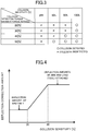
- the collision detection unit 33 compares the collision detection torque, which is the difference between the kinetic torque and the motor generation torque that has actually acted on the motor 21 through the control from the current control unit 32, with a collision detection threshold value.
- the collision detection threshold value is determined in accordance with the collision sensitivity set in advance. If the collision detection torque is equal to or more than the collision detection threshold value, it means that a collision has occurred.
- the collision sensitivity is settable by a user.
- a threshold range is provided in accordance with the sensitivity to avoid erroneous detection of a collision and achieve accurate detection of a collision.
- the collision detection torque maximum torque ratio
- the detection result is not regarded as "collision” if the collision sensitivity is set to 20%, 50%, or 80%.
- the collision sensitivity is set to 100%, the detection result is not regarded as a "collision.” That is, the collision detection threshold value is set to 80% or more and less than 100%.
- the collision detection torque (maximum torque ratio) is 30%, the detection result is similar to the case of 20%.
- the collision detection threshold value is set with a collision sensitivity of 50% or more and less than 80%.
- the collision sensitivity is set to 50%, the detection result is not regarded as a "collision", whereas if the collision sensitivity is set to 80%, the detection result is regarded as a "collision.”
- the collision detection threshold value is set at a collision sensitivity of 20% or more and less than 50%.
- the collision sensitivity is set to 20%, the detection result is not regarded as a "collision", whereas if the collision sensitivity is set to 50% or more, the detection result is regarded as a "collision.”
- a collision is detected more frequently at higher collision sensitivity, and a collision is detected less frequently at lower collision sensitivity.
- a collision is detected more frequently at higher collision sensitivity, and a collision is detected less frequently at lower collision sensitivity.
- high collision sensitivity even a small impact is regarded as a "collision.”
- low collision sensitivity a small impact is not regarded as a "collision.”
- the magnitude of the collision detection threshold value is determined in accordance with the collision sensitivity that is set. Therefore, it can be said that the set collision sensitivity represents the accuracy of the load information.
- the collision sensitivity can be freely set in advance by the user with the input unit 31.
- the calculation unit 36 calculates a correction amount for correcting the deflection amount of the robot arm 10 based on the collision sensitivity that has been input.
- the relation between the deflection correction amount and the collision sensitivity will be described below.
- the collision sensitivity is high, a collision is detected quick. It may therefore be possible to consider that the load information on the tool 18 attached to the robot arm 10 is accurate. On the other hand, if the collision sensitivity is low, a collision is detected too late. Thus, the load information on the tool 18 attached to the robot arm 10 is unreliable.
- the deflection correction amount may be set to be larger as the collision sensitivity increases.
- the load information on the tool 18 may be considered to be accurate, and the deflection correction amount may be calculated in consideration of the deflection amount caused by the load and the deflection amount due to the mass of the robot arm 10.
- the deflection correction amount may be calculated solely in consideration of the deflection amount due to the mass of the robot arm 10.
- the deflection correction amount may be calculated so as to gradually increase as the collision sensitivity increases in consideration of the deflection amount caused by the load and the deflection amount due to the mass of the robot arm 10.
- the correction amount calculated by the calculation unit 36 is transmitted to the storage unit 34 and stored therein.
- the comparison unit 37 compares the load information and the collision sensitivity which are set in advance at the time of creation of the operation program with the load information and the collision sensitivity newly input before execution of the operation program.
- the program modification unit 38 modifies the operation program based on the result of comparison by the comparison unit 37. Specifically, when the difference between the load information set in advance and the load information newly input is larger than a predetermined threshold value (such as a case where the tool 18 larger in mass than the tool 18 that has been set at the time of creation of the operation program is attached to the robot arm 10), the deflection amount of the robot arm 10 is larger than that assumed.
- a predetermined threshold value such as a case where the tool 18 larger in mass than the tool 18 that has been set at the time of creation of the operation program is attached to the robot arm 10
- the difference between the collision sensitivity set in advance and the collision sensitivity newly input is larger than the predetermined threshold value (such as a case where the collision sensitivity set at the time of creation of the operation program is 80% and the collision sensitivity newly input is 20%), a collision is detected too late, and the information on the tool 18 attached to the robot arm 10 therefore becomes unreliable.
- the predetermined threshold value such as a case where the collision sensitivity set at the time of creation of the operation program is 80% and the collision sensitivity newly input is 20%
- the program modification unit 38 modifies the operation program so that the robot arm 10 operates with a suitable correction amount in accordance with the new load information and collision sensitivity.
- step S101 the load information and the collision sensitivity that have been input are read, and the process proceeds to step S102.
- step S102 it is determined whether the load information and the collision sensitivity set at the time of creation (teaching) of the operation program and the load information and the collision sensitivity newly input are different from each other. If the determination in step S102 indicates "YES”, the process proceeds to step S103. If the determination in step S102 indicates "NO”, the process proceeds to step S106.
- step S103 the process transitions to an operation of modifying a teaching point in the operation program and proceeds to step S104.
- step S104 the deflection correction amount for each teaching point is calculated, and the process proceeds to step S105.
- step S105 the user determines whether to modify a teaching point, and the process proceeds to step S106.
- the user has a chance to make such determination because, like the teaching playback method, some teaching operations may be programmed by taking the deflection amount into account.
- step S106 the operation of the robot 1 is started in accordance with the operation program, and the process proceeds to step S107.
- step S107 while the robot arm 10 moves along the travel path, the deflection correction amount is calculated based on the gravitational torque at each interpolation point on the travel path, and the process proceeds to step S108.
- the interpolation point denotes a target position in each control period while the robot arm 10 moves between the teaching point A and the teaching point B.
- step S108 while the robot arm 10 moves along the travel path, the deflection correction is executed in real time, and the process proceeds to step S109.
- step S109 whether the robot arm 10 has reached the teaching point B is determined. If the determination in step S109 indicates "YES”, the deflection correction process is ended. If the determination in step S109 indicates "NO”, the process proceeds to step S107 and the process is repeated.
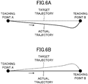
- FIGS. 6A and 6B are diagrams each for describing a difference between a target trajectory and an actual trajectory while the robot arm 10 is moved from the teaching point A to the teaching point B.
- the target trajectory is indicated by a dotted line and the actual trajectory is indicated by a solid line.
- the robot arm 10 can possibly come into contact with an unillustrated workpiece in the middle of the travel path.
- the robot arm 10 is moved while taking deflection amount of the robot arm 10 into account and correcting the deflection amount of the robot arm 10. Specifically, the robot arm 10 is moved from the teaching point A to the teaching point B along the target trajectory, the shape of which is a vertically inverted shape of the actual trajectory indicated by the solid line in FIG. 6A .
- the deflection of the robot arm 10 is canceled out in this manner, and it is possible to move the robot arm 10 along the actual trajectory that is a straight line between the teaching point A and the teaching point B as illustrated in FIG. 6B .
Landscapes
- Engineering & Computer Science (AREA)
- Robotics (AREA)
- Mechanical Engineering (AREA)
- Automation & Control Theory (AREA)
- Manipulator (AREA)
- Numerical Control (AREA)
Applications Claiming Priority (2)
| Application Number | Priority Date | Filing Date | Title |
|---|---|---|---|
| JP2018091385 | 2018-05-10 | ||
| PCT/JP2019/007077 WO2019215998A1 (ja) | 2018-05-10 | 2019-02-25 | ロボットの制御方法 |
Publications (2)
| Publication Number | Publication Date |
|---|---|
| EP3792011A1 true EP3792011A1 (de) | 2021-03-17 |
| EP3792011A4 EP3792011A4 (de) | 2021-07-07 |
Family
ID=68467407
Family Applications (1)
| Application Number | Title | Priority Date | Filing Date |
|---|---|---|---|
| EP19800374.1A Pending EP3792011A4 (de) | 2018-05-10 | 2019-02-25 | Robotersteuerungsverfahren |
Country Status (5)
| Country | Link |
|---|---|
| US (1) | US11890759B2 (de) |
| EP (1) | EP3792011A4 (de) |
| JP (1) | JP7165951B2 (de) |
| CN (1) | CN112041125B (de) |
| WO (1) | WO2019215998A1 (de) |
Families Citing this family (4)
| Publication number | Priority date | Publication date | Assignee | Title |
|---|---|---|---|---|
| JP7105646B2 (ja) * | 2018-08-02 | 2022-07-25 | 株式会社神戸製鋼所 | ロボット制御装置、ロボット制御方法及びプログラム |
| SE545353C2 (en) * | 2020-04-06 | 2023-07-18 | Husqvarna Ab | Adaptable operation for a robotic lawnmower |
| CN114061580B (zh) * | 2020-05-22 | 2023-12-29 | 梅卡曼德(北京)机器人科技有限公司 | 基于对称程度的机器人抓取方法、装置、电子设备及介质 |
| WO2022269927A1 (ja) * | 2021-06-25 | 2022-12-29 | ファナック株式会社 | プログラム作成装置 |
Family Cites Families (22)
| Publication number | Priority date | Publication date | Assignee | Title |
|---|---|---|---|---|
| JPS493765B1 (de) | 1969-10-22 | 1974-01-28 | ||
| JP2645004B2 (ja) * | 1987-02-27 | 1997-08-25 | 株式会社東芝 | 多自由度マニピユレータの制御装置 |
| JPH0434604A (ja) | 1990-05-31 | 1992-02-05 | Toshiba Corp | ロボットの位置補正方法及び位置補正装置 |
| JP3493765B2 (ja) | 1994-10-25 | 2004-02-03 | 株式会社安川電機 | 産業用ロボットの制御方法とその装置 |
| DE19837595B4 (de) * | 1998-08-19 | 2004-06-03 | Kuka Roboter Gmbh | Verfahren und Vorrichtung zum Gewichtsausgleich eines Roboterarms |
| CN100413657C (zh) * | 2003-07-29 | 2008-08-27 | 松下电器产业株式会社 | 控制机械手的方法 |
| EP1652634B1 (de) * | 2003-07-29 | 2011-12-28 | Panasonic Corporation | Roboterarmsteuerverfahren und -steuervorrichtung |
| JP2005052913A (ja) * | 2003-07-31 | 2005-03-03 | Nachi Fujikoshi Corp | ロボット制御装置 |
| JP2007190662A (ja) | 2006-01-23 | 2007-08-02 | Yaskawa Electric Corp | 産業用ロボットおよびたわみ補正方法 |
| US7313464B1 (en) * | 2006-09-05 | 2007-12-25 | Adept Technology Inc. | Bin-picking system for randomly positioned objects |
| US8655429B2 (en) * | 2007-06-29 | 2014-02-18 | Accuray Incorporated | Robotic arm for a radiation treatment system |
| JP2010069585A (ja) | 2008-09-19 | 2010-04-02 | Yaskawa Electric Corp | 衝突検出装置及び方法並びにロボット制御装置 |
| JP2010231575A (ja) | 2009-03-27 | 2010-10-14 | Kobe Steel Ltd | ロボットのオフライン教示装置、ロボットのオフライン教示方法、及びロボットシステム |
| JP5170175B2 (ja) | 2010-06-30 | 2013-03-27 | 株式会社安川電機 | ロボットシステム |
| JP6226716B2 (ja) * | 2013-11-22 | 2017-11-08 | 株式会社ミツトヨ | アーム型三次元測定機及びアーム型三次元測定機における撓み補正方法 |
| KR101683526B1 (ko) * | 2015-02-12 | 2016-12-07 | 현대자동차 주식회사 | 중력 보상 링키지 유니트 |
| WO2017170317A1 (ja) * | 2016-03-29 | 2017-10-05 | パナソニックIpマネジメント株式会社 | モータ制御装置 |
| US11911045B2 (en) * | 2017-10-30 | 2024-02-27 | Cllag GmbH International | Method for operating a powered articulating multi-clip applier |
| US20230146947A1 (en) * | 2017-10-30 | 2023-05-11 | Cilag Gmbh International | Method of hub communication with surgical instrument systems |
| US11564756B2 (en) * | 2017-10-30 | 2023-01-31 | Cilag Gmbh International | Method of hub communication with surgical instrument systems |
| US12062442B2 (en) * | 2017-12-28 | 2024-08-13 | Cilag Gmbh International | Method for operating surgical instrument systems |
| EP3819087A4 (de) * | 2018-07-02 | 2021-08-18 | Panasonic Intellectual Property Management Co., Ltd. | Robotersteuerungsverfahren und robotersteuerungsvorrichtung |
-
2019
- 2019-02-25 CN CN201980028971.8A patent/CN112041125B/zh active Active
- 2019-02-25 WO PCT/JP2019/007077 patent/WO2019215998A1/ja not_active Ceased
- 2019-02-25 JP JP2020518155A patent/JP7165951B2/ja active Active
- 2019-02-25 EP EP19800374.1A patent/EP3792011A4/de active Pending
-
2020
- 2020-10-29 US US17/083,591 patent/US11890759B2/en active Active
Also Published As
| Publication number | Publication date |
|---|---|
| US11890759B2 (en) | 2024-02-06 |
| JP7165951B2 (ja) | 2022-11-07 |
| CN112041125A (zh) | 2020-12-04 |
| CN112041125B (zh) | 2023-11-24 |
| JPWO2019215998A1 (ja) | 2021-05-20 |
| EP3792011A4 (de) | 2021-07-07 |
| WO2019215998A1 (ja) | 2019-11-14 |
| US20210039256A1 (en) | 2021-02-11 |
Similar Documents
| Publication | Publication Date | Title |
|---|---|---|
| US11890759B2 (en) | Robot control method | |
| KR101581095B1 (ko) | 다관절형 로봇의 제어 장치, 제어 방법 및 제어 프로그램을 기록한 컴퓨터 판독가능한 기록 매체 | |
| JP2008296310A (ja) | 加工ロボットの制御装置 | |
| JP5897644B2 (ja) | ロボットの制御装置 | |
| JPWO2007111252A1 (ja) | マニピュレータの制御方法および制御システム | |
| JP2010231575A (ja) | ロボットのオフライン教示装置、ロボットのオフライン教示方法、及びロボットシステム | |
| CN108748144B (zh) | 一种人机协作机械臂的碰撞识别方法 | |
| US20190184577A1 (en) | Robot system | |
| US20150051735A1 (en) | Control apparatus of robot, robot, and program thereof | |
| JP7164368B2 (ja) | ロボット装置 | |
| US20170043481A1 (en) | Robot controller inhibiting shaking of tool tip in robot equipped with travel axis | |
| CN112621740B (zh) | 具备具有操作部的机器人的机器人系统以及控制机器人的方法 | |
| JP2009045678A (ja) | ロボットの作業成否判定方法およびロボットシステム | |
| JP2013223895A (ja) | ロボット制御方法及びロボット制御装置 | |
| CN109476024B (zh) | 机器人的控制方法以及焊接方法 | |
| WO2020255312A1 (ja) | ロボットの動作調整装置、動作制御システムおよびロボットシステム | |
| JP5708091B2 (ja) | ロボットの制御方法およびロボットの制御装置 | |
| CN114571447A (zh) | 机器人控制装置 | |
| EP3819087A1 (de) | Robotersteuerungsverfahren und robotersteuerungsvorrichtung | |
| JP2007066001A (ja) | ロボットの制御装置 | |
| JP5803179B2 (ja) | ロボットの制御方法およびロボットの制御装置 | |
| US12472624B2 (en) | Spring constant correction device, method therefor, and recording medium | |
| JP7687081B2 (ja) | 力制御パラメーターの調整方法および力制御パラメーター調整装置 | |
| JPH07334228A (ja) | ロボットの教示データ補正装置 | |
| KR100736136B1 (ko) | 작업성을 고려한 용접로봇의 제어방법 |
Legal Events
| Date | Code | Title | Description |
|---|---|---|---|
| STAA | Information on the status of an ep patent application or granted ep patent |
Free format text: STATUS: THE INTERNATIONAL PUBLICATION HAS BEEN MADE |
|
| PUAI | Public reference made under article 153(3) epc to a published international application that has entered the european phase |
Free format text: ORIGINAL CODE: 0009012 |
|
| STAA | Information on the status of an ep patent application or granted ep patent |
Free format text: STATUS: REQUEST FOR EXAMINATION WAS MADE |
|
| 17P | Request for examination filed |
Effective date: 20201023 |
|
| AK | Designated contracting states |
Kind code of ref document: A1 Designated state(s): AL AT BE BG CH CY CZ DE DK EE ES FI FR GB GR HR HU IE IS IT LI LT LU LV MC MK MT NL NO PL PT RO RS SE SI SK SM TR |
|
| AX | Request for extension of the european patent |
Extension state: BA ME |
|
| REG | Reference to a national code |
Ref country code: DE Ref legal event code: R079 Free format text: PREVIOUS MAIN CLASS: B25J0009100000 Ipc: B25J0009160000 |
|
| A4 | Supplementary search report drawn up and despatched |
Effective date: 20210609 |
|
| RIC1 | Information provided on ipc code assigned before grant |
Ipc: B25J 9/16 20060101AFI20210603BHEP |
|
| DAV | Request for validation of the european patent (deleted) | ||
| DAX | Request for extension of the european patent (deleted) | ||
| STAA | Information on the status of an ep patent application or granted ep patent |
Free format text: STATUS: EXAMINATION IS IN PROGRESS |
|
| 17Q | First examination report despatched |
Effective date: 20231110 |