EP3790177A1 - Verfahren zum betreiben eines elektrischen bearbeitungsgeräts und elektrisches bearbeitungsgerät - Google Patents
Verfahren zum betreiben eines elektrischen bearbeitungsgeräts und elektrisches bearbeitungsgerät Download PDFInfo
- Publication number
- EP3790177A1 EP3790177A1 EP19196206.7A EP19196206A EP3790177A1 EP 3790177 A1 EP3790177 A1 EP 3790177A1 EP 19196206 A EP19196206 A EP 19196206A EP 3790177 A1 EP3790177 A1 EP 3790177A1
- Authority
- EP
- European Patent Office
- Prior art keywords
- motor
- state
- voltage
- control
- open
- Prior art date
- Legal status (The legal status is an assumption and is not a legal conclusion. Google has not performed a legal analysis and makes no representation as to the accuracy of the status listed.)
- Granted
Links
Images



Classifications
-
- H—ELECTRICITY
- H02—GENERATION; CONVERSION OR DISTRIBUTION OF ELECTRIC POWER
- H02M—APPARATUS FOR CONVERSION BETWEEN AC AND AC, BETWEEN AC AND DC, OR BETWEEN DC AND DC, AND FOR USE WITH MAINS OR SIMILAR POWER SUPPLY SYSTEMS; CONVERSION OF DC OR AC INPUT POWER INTO SURGE OUTPUT POWER; CONTROL OR REGULATION THEREOF
- H02M1/00—Details of apparatus for conversion
- H02M1/32—Means for protecting converters other than automatic disconnection
-
- A—HUMAN NECESSITIES
- A01—AGRICULTURE; FORESTRY; ANIMAL HUSBANDRY; HUNTING; TRAPPING; FISHING
- A01G—HORTICULTURE; CULTIVATION OF VEGETABLES, FLOWERS, RICE, FRUIT, VINES, HOPS OR SEAWEED; FORESTRY; WATERING
- A01G3/00—Cutting implements specially adapted for horticultural purposes; Delimbing standing trees
- A01G3/04—Apparatus for trimming hedges, e.g. hedge shears
- A01G3/047—Apparatus for trimming hedges, e.g. hedge shears portable
- A01G3/053—Apparatus for trimming hedges, e.g. hedge shears portable motor-driven
-
- H—ELECTRICITY
- H01—ELECTRIC ELEMENTS
- H01H—ELECTRIC SWITCHES; RELAYS; SELECTORS; EMERGENCY PROTECTIVE DEVICES
- H01H9/00—Details of switching devices, not covered by groups H01H1/00 - H01H7/00
- H01H9/54—Circuit arrangements not adapted to a particular application of the switching device and for which no provision exists elsewhere
-
- A—HUMAN NECESSITIES
- A01—AGRICULTURE; FORESTRY; ANIMAL HUSBANDRY; HUNTING; TRAPPING; FISHING
- A01D—HARVESTING; MOWING
- A01D34/00—Mowers; Mowing apparatus of harvesters
-
- A—HUMAN NECESSITIES
- A01—AGRICULTURE; FORESTRY; ANIMAL HUSBANDRY; HUNTING; TRAPPING; FISHING
- A01D—HARVESTING; MOWING
- A01D69/00—Driving mechanisms or parts thereof for harvesters or mowers
- A01D69/02—Driving mechanisms or parts thereof for harvesters or mowers electric
-
- A—HUMAN NECESSITIES
- A01—AGRICULTURE; FORESTRY; ANIMAL HUSBANDRY; HUNTING; TRAPPING; FISHING
- A01G—HORTICULTURE; CULTIVATION OF VEGETABLES, FLOWERS, RICE, FRUIT, VINES, HOPS OR SEAWEED; FORESTRY; WATERING
- A01G3/00—Cutting implements specially adapted for horticultural purposes; Delimbing standing trees
- A01G3/02—Secateurs; Flower or fruit shears
- A01G3/033—Secateurs; Flower or fruit shears having motor-driven blades
- A01G3/037—Secateurs; Flower or fruit shears having motor-driven blades the driving means being an electric motor
-
- A—HUMAN NECESSITIES
- A01—AGRICULTURE; FORESTRY; ANIMAL HUSBANDRY; HUNTING; TRAPPING; FISHING
- A01G—HORTICULTURE; CULTIVATION OF VEGETABLES, FLOWERS, RICE, FRUIT, VINES, HOPS OR SEAWEED; FORESTRY; WATERING
- A01G3/00—Cutting implements specially adapted for horticultural purposes; Delimbing standing trees
- A01G3/08—Other tools for pruning, branching or delimbing standing trees
- A01G3/085—Motor-driven saws for pruning or branching
-
- G—PHYSICS
- G01—MEASURING; TESTING
- G01R—MEASURING ELECTRIC VARIABLES; MEASURING MAGNETIC VARIABLES
- G01R31/00—Arrangements for testing electric properties; Arrangements for locating electric faults; Arrangements for electrical testing characterised by what is being tested not provided for elsewhere
- G01R31/327—Testing of circuit interrupters, switches or circuit-breakers
- G01R31/3277—Testing of circuit interrupters, switches or circuit-breakers of low voltage devices, e.g. domestic or industrial devices, such as motor protections, relays, rotation switches
-
- G—PHYSICS
- G01—MEASURING; TESTING
- G01R—MEASURING ELECTRIC VARIABLES; MEASURING MAGNETIC VARIABLES
- G01R31/00—Arrangements for testing electric properties; Arrangements for locating electric faults; Arrangements for electrical testing characterised by what is being tested not provided for elsewhere
- G01R31/34—Testing dynamo-electric machines
-
- H—ELECTRICITY
- H02—GENERATION; CONVERSION OR DISTRIBUTION OF ELECTRIC POWER
- H02K—DYNAMO-ELECTRIC MACHINES
- H02K11/00—Structural association of dynamo-electric machines with electric components or with devices for shielding, monitoring or protection
- H02K11/30—Structural association with control circuits or drive circuits
- H02K11/33—Drive circuits, e.g. power electronics
-
- H—ELECTRICITY
- H02—GENERATION; CONVERSION OR DISTRIBUTION OF ELECTRIC POWER
- H02K—DYNAMO-ELECTRIC MACHINES
- H02K7/00—Arrangements for handling mechanical energy structurally associated with dynamo-electric machines, e.g. structural association with mechanical driving motors or auxiliary dynamo-electric machines
- H02K7/14—Structural association with mechanical loads, e.g. with hand-held machine tools or fans
- H02K7/145—Hand-held machine tool
-
- H—ELECTRICITY
- H02—GENERATION; CONVERSION OR DISTRIBUTION OF ELECTRIC POWER
- H02P—CONTROL OR REGULATION OF ELECTRIC MOTORS, ELECTRIC GENERATORS OR DYNAMO-ELECTRIC CONVERTERS; CONTROLLING TRANSFORMERS, REACTORS OR CHOKE COILS
- H02P1/00—Arrangements for starting electric motors or dynamo-electric converters
- H02P1/16—Arrangements for starting electric motors or dynamo-electric converters for starting dynamo-electric motors or dynamo-electric converters
-
- H—ELECTRICITY
- H02—GENERATION; CONVERSION OR DISTRIBUTION OF ELECTRIC POWER
- H02P—CONTROL OR REGULATION OF ELECTRIC MOTORS, ELECTRIC GENERATORS OR DYNAMO-ELECTRIC CONVERTERS; CONTROLLING TRANSFORMERS, REACTORS OR CHOKE COILS
- H02P29/00—Arrangements for regulating or controlling electric motors, appropriate for both AC and DC motors
- H02P29/40—Regulating or controlling the amount of current drawn or delivered by the motor for controlling the mechanical load
-
- H—ELECTRICITY
- H02—GENERATION; CONVERSION OR DISTRIBUTION OF ELECTRIC POWER
- H02P—CONTROL OR REGULATION OF ELECTRIC MOTORS, ELECTRIC GENERATORS OR DYNAMO-ELECTRIC CONVERTERS; CONTROLLING TRANSFORMERS, REACTORS OR CHOKE COILS
- H02P3/00—Arrangements for stopping or slowing electric motors, generators, or dynamo-electric converters
- H02P3/06—Arrangements for stopping or slowing electric motors, generators, or dynamo-electric converters for stopping or slowing an individual dynamo-electric motor or dynamo-electric converter
- H02P3/08—Arrangements for stopping or slowing electric motors, generators, or dynamo-electric converters for stopping or slowing an individual dynamo-electric motor or dynamo-electric converter for stopping or slowing a DC motor
- H02P3/12—Arrangements for stopping or slowing electric motors, generators, or dynamo-electric converters for stopping or slowing an individual dynamo-electric motor or dynamo-electric converter for stopping or slowing a DC motor by short-circuit or resistive braking
Definitions
- the invention relates to a method for operating an electrical processing device and an electrical processing device.
- the object of the invention is to provide a method for operating an electrical processing device and an electrical processing device, each of which has improved properties.
- the invention solves this problem by providing a method with the features of claim 1 and an electrical processing device with the features of claim 14.
- Advantageous developments and / or refinements of the invention are described in the dependent claims.
- the method according to the invention is designed or configured for, in particular automatically, operating an electrical processing device.
- the processing device has a user-operated control switch, motor electronics having, in particular an electric, motor control and an electric drive motor.
- the control switch is electrically connected or connected in series on the input side to an, in particular electrical, drive voltage source and on the output side to the motor electronics.
- the motor electronics are electrically connected or connected in series to the electric drive motor by means of the motor control.
- the method has the following steps: a) Monitoring, in particular automatic monitoring, whether an input voltage at the engine electronics, in particular either, meets a closed criterion or an open criterion.
- the closed criterion is characteristic of a closed switching state of the control switch.
- the open criterion is characteristic of an open switching state of the control switch. b) if the open criterion is met, operating, in particular automatic operation, the engine control in a state or mode from an open-state set or open-mode set.
- the open-state set has a voltage control state or voltage control mode for, in particular automatic limiting of an increase in the input voltage caused by the electric drive motor running down or coasting down, in particular when the control switch is in the open switching state.
- the processing device can be a hand-held, in particular floor-mounted or hand-carried, processing device.
- hand-held, in particular hand-carried, processing device can mean that the processing device can have a maximum mass of 50 kilograms (kg), in particular 20 kg, in particular 10 kg.
- the processing device can be a gardening, forestry and / or construction processing device.
- the processing device can be a saw, a pruner, a brush cutter, a hedge trimmer, a hedge cutter, a blower, a leaf blower, a pruning shears, a power cutter, a sweeper, a rotary brush, a sweeping brush, a lawn mower, a scarifier or a grass shear be.
- the electric drive motor can be designed to drive a machining tool of the machining device.
- the control switch can be designed to establish an electrical connection between the drive voltage source and the motor electronics in the closed switching state and to disconnect it in the open switching state. Additionally or alternatively, the control switch can be referred to as a disconnecting switch. Furthermore, additionally or alternatively, the processing device can be designed in such a way that the control switch can be actuated directly or indirectly by a user. Furthermore, additionally or alternatively, the operating switch can be an operating switch that automatically resets to the open switching state.
- the engine electronics can have an engine electronics circuit board.
- the motor control can be referred to as an output stage.
- the monitoring can include measuring the input voltage.
- the closed criterion and the open criterion can be different.
- Step a) can be carried out continuously. Additionally or alternatively, step b) can be carried out at the same time and / or at the same time as step a). Furthermore, additionally or alternatively, step b) can be carried out until the closed criterion can be met.
- the state from the open state set in particular the voltage control state, does not need or can not allow the electric drive motor to be supplied with electrical output power from the drive voltage source.
- the electric drive motor has a mechanical commutator.
- the electric drive motor is a direct current machine.
- the mechanical commutator can cause commutation peaks or high commutation pulses or tear-off sparks when the electric drive motor runs down, the commutation peaks causing the input voltage to rise.
- brushes of the commutator can each touch two lamellae of the commutator for a short time and thus cause the breakaway sparks.
- the closed criterion is that the input voltage is equal to or greater than a first voltage limit value and / or an increase, in particular over time, in the input voltage is equal to or greater than a, in particular over time, voltage increase limit value.
- the open criterion is that the input voltage is equal to or less than a second voltage limit value and / or a, in particular a temporal, drop in the input voltage is equal to or less than a, in particular a temporal, voltage drop limit value.
- the voltage control state makes it possible to avoid incorrectly fulfilling the closed criterion, although the operating switch can have the open switching state.
- the voltage control state enables the monitoring of whether the input voltage fulfills the closed criterion, in particular or the open criterion, can function.
- the monitoring can include a comparison of the input voltage with the first voltage limit value and / or the second voltage limit value.
- the processing device has a power path and an information path that is different from the power path.
- the power path electrically connects the drive voltage source to the motor electronics on the input side for a flow of electrical drive power from the drive voltage source to the motor electronics, in particular when the control switch is closed.
- the operating switch is electrically arranged or connected in series in the power path.
- the information path electrically, in particular continuously, connects the drive voltage source to the motor electronics for information about a voltage source value of the drive voltage source.
- the method has the step of specifying, in particular automatically specifying, the closed criterion, in particular the first voltage limit value and / or the voltage rise limit value, if any, and / or the open criterion, in particular the second voltage limit value and / or the voltage drop limit value, if any available, depending on the information provided about the voltage source value.
- the closed criterion and / or the open criterion can be currently adapted to the voltage source value.
- the drive voltage source can have an accumulator.
- the voltage source value can drop with increasing discharge of the accumulator.
- the information can be the voltage source value.
- the information path does not need or cannot electrically connect the drive voltage source to the motor electronics for a flow of electrical drive power from the drive voltage source to the motor electronics.
- the information path can be referred to as a bypass line.
- the operating switch does not need or cannot be electrically arranged in the information path.
- the power path can also be referred to as a power line.
- the monitoring can include measuring the voltage source value and / or comparing the input voltage with the voltage source value.
- the second voltage limit value is smaller than the first voltage limit value.
- the second voltage limit value is at least 0.75 volts (V), in particular 1.5 V, less than the first voltage limit value. Additionally or alternatively, the second voltage limit value lies in a range from 0.8 times to 0.9 times the first voltage limit value.
- the first voltage limit value is smaller than the voltage source value.
- the first voltage limit is at least 0.25 V, in particular 0.5 V, less than the voltage source value.
- the first voltage limit value lies in a range from 0.85 times to 0.95 times the voltage source value.
- the first voltage limit value lies in a range from 7.5 V to 20.5 V, in particular up to 11.5 V.
- the second voltage limit value is in a range from 6 V, in particular from 7.5 V, to 20.5 V, in particular up to 10 V.
- the voltage source value is in a range from 8 V to 20.5 V, in particular up to 12 V.
- the monitoring of whether the input voltage meets the closed criterion, in particular or the open criterion does not function without the voltage control state according to the invention, in particular in contrast to high voltage values, such as 36 V.
- the input voltage can remain approximately at the level of the drive voltage or the voltage source value for a long time without the voltage control state according to the invention.
- no rapid voltage rise needs or cannot be detected in this area when the control switch is actuated again.
- a nominal voltage of the drive voltage source can be 10.8 V or 18 V.
- the method has the step: c) if the closed criterion is met, operating, in particular automatic operation, the motor control in an active state or active mode for, in particular automatically, supplying the electric drive motor with electrical power Output power from the drive voltage source, especially when the control switch is in the closed switching state.
- This in particular the active state, enables the electric drive motor to run, especially when the operating switch is in the closed switching state.
- step c) can be carried out before and / or after step b). Additionally or alternatively, either step c) or step b) can be carried out. Furthermore, additionally or alternatively, step c) can be carried out at the same time and / or at the same time as step a).
- step c) can be carried out, until the open criterion can be met.
- the active state with the open switching state of the operating switch can enable, in particular cause, the drop in the input voltage and thus the fulfillment of the open criterion.
- the active state does not need or cannot be from the open state set. In particular, the active state can be different from the voltage control state.
- step c) can have: operating the motor control in the active state for, in particular automatically, holding an output voltage on the motor electronics, in particular the motor control, or the electric drive motor at an, in particular constant, voltage value, in particular with an electrical voltage Output power from the drive voltage source and / or when the control switch is in the closed switching state.
- the voltage value of the output voltage can be or be specified as a function of the information provided about the voltage source value and / or information about the electric drive motor.
- the open-state set has the voltage control state for, in particular automatically, allowing an increase in the input voltage caused by the drive voltage source when the operating switch is in the closed switching state.
- This in particular the voltage control state, enables the closed criterion to be met when the operating switch is in the closed switching state. This thus enables the monitoring of whether the input voltage fulfills the closed criterion, in particular or the open criterion, can function.
- the open-state set has the voltage control state for, in particular automatically, holding the input voltage at an, in particular constant, voltage value, in particular the second voltage limit value, in particular when the operating switch is open.
- This initially makes it possible to avoid a further drop in the input voltage.
- the control switch is actuated again or when the switching state is closed, this makes it possible to keep an inrush current low.
- the voltage value, in particular the second voltage limit value can lie in a range as described above.
- hold at the voltage value can mean that the input voltage can be kept in a narrow range, for example plus / minus 0.25V, around the voltage value.
- the open state set has an inactive state or inactive mode different from the voltage control state for, in particular automatic, non-limiting of an increase in the input voltage caused by the expiring electric drive motor, in particular when the switching state is open of the control switch.
- Step b) has: temporally after the operation of the motor control in the voltage control state, in particular automatic operation of the motor control in the inactive state.
- the operation in the inactive state can be a non-operation.
- step b) can include operating the motor control in the inactive state if the input voltage can no longer be kept at the voltage value, if present, and / or if the expiring or even expired electric drive motor is not high or even none at all Increase in input voltage.
- the inactive state can be different from the active state.
- the motor control has at least one, in particular first, motor switching element and at least one, in particular first, protective element, in particular a protective diode, to protect the motor switching element, in particular from damage caused by the running down electric drive motor.
- the protective element enables an increase in the input voltage caused by the expiring electric drive motor.
- the protective element can be arranged or connected electrically antiparallel to the motor switching element.
- the protective diode can be referred to as a freewheeling diode or a body diode.
- the motor switching element can be a transistor.
- the motor control has a, in particular the, controllable first motor switching element and / or a controllable second motor switching element.
- the first motor switching element is arranged electrically or connected in series after the control switch and upstream of the electric drive motor.
- the second motor switching element is electrically arranged or connected in parallel to the electric drive motor.
- Operating the motor control in the active state comprises: controlling, in particular automatic control, of the first motor switching element alternately in an on state and in an off state, in particular by means of pulse width modulation.
- the operation of the motor control in the voltage control state includes: control, in particular automatic control, of the first Motor switching element alternately in the on state and in the off state, in particular by means of pulse width modulation.
- the operation of the motor control in the inactive state includes: controlling, in particular automatic controlling, the first motor switching element continuously in the off state.
- the operation of the motor control in the active state includes: control, in particular automatic control, of the second motor switching element alternately in an on state and in an off state, in particular by means of pulse width modulation.
- the operation of the motor control in the voltage control state includes: control, in particular automatic control, of the second motor switching element alternately in the on state and in the off state, in particular by means of pulse width modulation.
- the operation of the motor control in the inactive state includes: controlling, in particular automatic controlling, the second motor switching element continuously in the off state.
- the control in the active state enables the electric drive motor to be supplied with electrical output power from the drive voltage source when the operating switch is closed and / or the input voltage drops when the operating switch is open.
- control in the voltage control state with the switching state of the operating switch open enables the increase in the input voltage to be limited, in particular maintaining the input voltage, and / or allowing the input voltage to rise when the switching state of the operating switch is closed.
- control in the inactive state in particular when the switching state of the operating switch is open, enables the increase in the input voltage not to be limited.
- the first motor switching element and the second motor switching element can be operated as a voltage controller, in particular as a voltage regulator. Additionally or alternatively, the first motor switching element and the second motor switching element can be different. Furthermore, additionally or alternatively, the first motor switching element can be referred to as a high-side switching element and / or the second motor switching element can be referred to as a low-side switching element. In addition or as an alternative, this can / can second motor switching element and / or the electric drive motor can each be arranged electrically or connected in series after the first motor switching element and in front of ground. Furthermore, additionally or alternatively, the first motor switching element and the second motor switching element can each be a transistor. Additionally or alternatively, the on-state and the off-state can be different.
- the on state can be referred to as conductive and / or the off state can be referred to as non-conductive or disconnecting state.
- permanent can be referred to as permanent and / or mean in one state and not in the other state.
- the operation of the motor control in the active state and / or in the voltage control state can include: controlling the first motor switching element and the second motor switching element by means of complementary pulse width modulation,
- the engine electronics have at least one intermediate circuit capacitor.
- the input voltage is an intermediate circuit voltage of the at least one intermediate circuit capacitor.
- the intermediate circuit capacitor can be electrically arranged or connected in series after the operating switch and before the, in particular the first, motor switching element and / or before the protective element and / or before ground.
- the intermediate circuit capacitor, the protective diode, the second motor switching element, in particular the first motor switching element, and the electric drive motor can form an up converter or a boost converter, in particular at least partially or even completely.
- the method has the step: if the closed criterion is met, executing, in particular automatically executing, a self-test of the processing device and / or outputting, in particular automatic outputting, user-perceptible information, in particular as a function of a result of the self-test .
- the voltage control state enables the self-test to be carried out and / or to be output only if the operating switch is in the closed switching state. This enables, in particular the voltage control state, to avoid undesirable effects, in particular as a function of incorrectly fulfilling the closed criterion, although the operating switch can have the open switching state.
- an undesirable effect could be that a result of the self-test is that the closed criterion is met, although the operating switch has the open switching state, and thus is recognized as an error and that this error is output.
- the output can be an optical and / or acoustic output.
- the electrical processing device has one, in particular the user-operated control switch, one, in particular the motor electronics, having a, in particular the, motor control and having a, in particular electrical, monitoring and control device and one, in particular the, electric drive motor.
- the control switch is designed on the input side for electrical connection to a, in particular the, drive voltage source and is electrically connected on the output side to the motor electronics.
- the motor electronics are electrically connected to the electric drive motor by means of the motor control.
- the monitoring and control device is designed or configured to monitor, in particular automatically, whether one, in particular the, input voltage to the engine electronics, in particular either, fulfills, in particular, the closed criterion or one, in particular the open criterion .
- the closed criterion is characteristic of one, in particular the closed, switching state of the control switch.
- the open criterion is characteristic of one, in particular the open, switching state of the control switch.
- the monitoring and control device is designed or configured for, in particular automatically, operating the motor control in one, in particular the, state from an, in particular the, open-state set.
- the open-state set has one, in particular the, voltage control state for, in particular automatically, limiting a, in particular the, increase in the input voltage caused by the decelerating electric drive motor.
- the processing device can enable the same advantage (s) as described above for the method.
- the processing device in particular the monitoring and control device, can be designed or configured to carry out a method as described above. Additionally or alternatively, the processing device can be designed or configured as described above for the method. Furthermore, additionally or alternatively, the monitoring and control device can have, in particular be, a microcontroller. Furthermore, additionally or alternatively, the processing device can be designed to carry, in particular to receive, in particular exchangeably, the drive voltage source having the accumulator.
- the machining device has the drive voltage source.
- the drive voltage source has an accumulator, in particular an accumulator.
- the input side of the operating switch is electrically connected to the drive voltage source.
- the drive voltage source can be designed as an exchangeable drive voltage source.
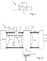
- Figs. 1 to 4 show an electrical processing device 1 according to the invention.
- the processing device 1 has a user-operated control switch 2, motor electronics 3 having a motor control 4 and having a monitoring and control device 15 and an electric drive motor 6.
- the operating switch 2 is designed on the input side to be electrically connected to a drive voltage source 70 and is electrically connected to the motor electronics 3 on the output side.
- the motor electronics 3 are electrically connected to the electric drive motor 6 by means of the motor control 4.
- the monitoring and control device 15 is designed to monitor whether an input voltage Uin at the engine electronics 3 fulfills a closed criterion ck or an open criterion ok.
- the closed criterion ck is characteristic of a closed switching state of the operating switch 2.
- the open criterion ok is characteristic of an open switching state of control switch 2. Furthermore, if the open criterion ok is met, the monitoring and control device 15 is designed to operate the motor control 4 in a state SZ, IZ from an open state set.
- the open-state set has a voltage control state SZ for limiting an increase in the input voltage Uin caused by the decelerating electric drive motor 6, in particular when the operating switch 2 is in the open switching state.
- Fig. 8 shows a method according to the invention for operating the electrical processing device 1, in particular by means of the monitoring and control device 15.
- the processing device 1 has the user-operated control switch 2, the motor electronics 3 having the motor control 4 and the electric drive motor 6.
- the control switch 2 is electrically connected on the input side to the drive voltage source 7 and on the output side to the motor electronics 3.
- the motor electronics 3 are electrically connected to the electric drive motor 6 by means of the motor control 4.
- the method has the following steps: a) Monitoring whether the input voltage Uin at the engine electronics 3 meets the closed criterion ck or the open criterion ok, in particular by means of the monitoring and control device 15.
- the closed criterion ck is for the closed criterion Switching state closed of control switch 2 is characteristic.
- the open criterion ok is characteristic of the open switching state of control switch 2. b) if the open criterion is met, operating the motor control 4 in the state SZ, IZ from the open state set, in particular by means of the monitoring and control device 15.
- the open state set indicates the voltage control state SZ Limiting the increase in the input voltage Uin caused by the expiring electric drive motor 6.
- the processing device 2 has the drive voltage source 70.
- the drive voltage source 70 has an accumulator 19.
- the processing device 2 is a hedge trimmer.
- the processing device can be a saw, a pruner, a brush cutter, a hedge cutter, a blower, a leaf blower, a loppers, a power cutter, a sweeper, a roller broom, a sweeping brush, a lawn mower, a scarifier or a grass shear .
- the electric drive motor 6 also has a mechanical commutator 7.
- the electric drive motor 6 is a direct current machine 8.
- the mechanical commutator 7 causes commutation peaks KP when the electric drive motor 6 coasts down, as in FIG Fig 5 shown.
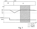
- the commutation peaks KP can cause the input voltage Uin to rise, as in Fig. 6 and 7th shown.
- the closed criterion ck is that the input voltage Uin is equal to or greater than a first voltage limit value U1.
- the closed criterion can additionally or alternatively be that a rise in the input voltage is equal to or greater than a voltage rise limit value.
- the open criterion is ok that the input voltage Uin is equal to or less than a second voltage limit value U2.
- the open criterion can additionally or alternatively be that a drop in the input voltage is equal to or less than a voltage drop limit value.
- the voltage control state SZ enables the closed criterion cK to be incorrectly fulfilled, as in FIG Fig. 6 shown at the beginning of the hatched area, though the control switch 2 has the open switching state open, as in Fig. 8 shown.
- the processing device 2 has a power path 9 and an information path 10 different from the power path 9.
- the power path 9 electrically connects the drive voltage source 70 to the motor electronics 3 on the input side for a flow of electrical drive power P7 from the drive voltage source 70 to the motor electronics 3, in particular in the closed switching state of the control switch 2.
- the control switch 2 is electrically arranged in the power path 9.
- the information path 10 electrically connects the drive voltage source 70 to the engine electronics 3, in particular the monitoring and control device 15, for information IfU7 about a voltage source value U7 of the drive voltage source 70.
- the method has the step of: specifying the closed criterion ck, in the exemplary embodiment shown of the first voltage limit value U1 and / or the open criterion ok, in the exemplary embodiment shown the second voltage limit value U2, depending on the information IfU7 provided about the voltage source value U7, in particular by means of the monitoring and control device 15.
- the information path 10 electrically connects the drive voltage source 70 to the motor electronics 3, in particular the monitoring and control device 15, for a flow of electrical power P15 from the drive voltage source 70 to the monitoring and control device 15 for operating the monitoring and control device 15, especially when the switch 2 is in the open switching state.
- the second voltage limit value U2 is smaller than the first voltage limit value U1.
- the second voltage limit value U2 is at least 0.75 V less than the first voltage limit value U1.
- the second voltage limit value U2 lies in a range from 0.8 times to 0.9 times the first voltage limit value U1.
- the first voltage limit value U1 is smaller than the voltage source value U7.
- the first voltage limit value U1 is at least 0.25 V less than the voltage source value U7.
- the first voltage limit value U1 lies in a range from 0.85 times to 0.95 times the voltage source value U7.
- the first voltage limit value U1 lies in a range from 7.5 V to 20.5 V.
- the second voltage limit value U2 lies in a range from 6 V to 20.5 V.
- the voltage source value U7 lies in a range from 8 V to 20.5 V.
- the input voltage can remain approximately at the level of the drive voltage or the voltage source value for a long time without the voltage control state according to the invention, as in FIG Fig. 7 shown. Thereby needs or can in this, in Fig. 7 hatched area, no rapid voltage rise can be detected when the control switch is pressed again. In other words, no switch detection or detection of the switching state is possible over a longer period of time.
- the method also has the step: c) if the closed criterion ck is met, operating the motor control 4 in an active state AZ to supply the electric drive motor 6 with electrical output power Pout from the drive voltage source 70, in particular when the control switch is in the closed state closed 2, in particular by means of the monitoring and control device 15.
- the active state AZ enables the input voltage Uin to drop and thus the open criterion ok to be met when the control switch 2 is open.
- the open-state quantity has the voltage control state SZ for allowing an increase in the input voltage Uin caused by the drive voltage source 70 when the switching state closed of the operating switch 2.
- the voltage control state SZ enables the closed criterion ck to be met when the control switch 2 is closed.
- the set of open states has the voltage control state SZ for holding the input voltage Uin at a voltage value U3, in the exemplary embodiment shown, the second voltage limit value U2, in particular when the switch 2 is in the open switching state.
- the voltage control state SZ initially enables a further drop in the input voltage Uin to be avoided.
- the open-state set also has an inactive state IZ, which differs from the voltage control state SZ, in order not to limit an increase in the input voltage Uin caused by the expiring electric drive motor 6, in particular when the switch 2 is in the open switch state.
- Step b) comprises: chronologically after the motor control 4 has been operated in the voltage control state, the motor control 4 is operated in the inactive state IZ.
- the motor control 4 has at least one, in particular first, motor switching element 12a and at least one, in particular first, protective element 13a, in particular a protective diode 14a, for protecting the motor switching element 12a.
- The, in particular the first, protective element 13a enables an increase in the input voltage Uin caused by the expiring electric drive motor 6.
- the, in particular the first, protective element 13a is arranged electrically antiparallel to the, in particular first, motor switching element 12a.
- the motor control 4 has the controllable first motor switching element 12a and a controllable second motor switching element 12b.
- the first motor switching element 12a is arranged electrically after the control switch 2 and in front of the electric drive motor 6.
- the second motor switching element 12b is electrically arranged parallel to the electric drive motor 6.
- Operating the motor control 4 in the active state AZ comprises: controlling the first motor switching element 12a alternately into an on state and into an off state off, in particular by means of pulse width modulation PWM, in particular by means of the monitoring and control device 15.
- the operation of the motor control 4 in the voltage control state SZ includes: Controlling the first motor switching element 12a alternately in the on state on and in the off state off, in particular by means of pulse width modulation PWM, in particular by means of the monitoring and control device 15.
- the operation of the motor control 4 in the inactive state IZ includes: Controlling the first motor switching element 12a continuously in the off state off, in particular by means of the monitoring and control device 15.
- the operation of the motor control 4 in the active state AZ includes: Controlling the second motor switching element 12b alternately in an on-state and in an off-state off, in particular by means of pulse width modulation PWM, in particular by means of the monitoring and control device 15.
- the operation of the motor control 4 in the voltage control state SZ includes: Controlling the second motor switching element 12b alternately in the on state on and in the off state off, in particular by means of pulse width modulation PWM, in particular by means of the monitoring and control device 15.
- the operation of the motor control 4 in the inactive state IZ includes: Controlling the second motor switching element 12b continuously in the off state off, in particular by means of the monitoring and control device 15.
- the operation of the motor control 4 in the active state AZ and in the voltage control state SZ includes: Controlling the first motor switching element 12a and the second motor switching element 12b by means of complementary pulse width modulation PWM.
- operating the motor control in the voltage control state can include: controlling the first motor switching element continuously in the off state.
- the motor control 4 has a second protective element 13b, in particular a protective diode 14b, for protecting the second motor switching element 12b.
- the second protective element 13b is electrically arranged antiparallel to the second motor switching element 12b.
- the engine electronics 3 also have at least one intermediate circuit capacitor 11.
- the input voltage Uin is an intermediate circuit voltage U11 of the at least one intermediate circuit capacitor 11.
- the intermediate circuit capacitor 11, the first protective diode 14a, the second motor switching element 12b, the first motor switching element 12a and the electric drive motor 6 form a step-up converter, as in FIG Fig. 4 shown.
- the intermediate circuit capacitor, the first protective diode, the second motor switching element and the electric drive motor can form a step-up converter.
- the electric drive motor 6 is connected as an inductance L in series with the protective diode 14a as a freewheeling diode D, behind which the intermediate circuit capacitor 11 as a charging capacitor C sums up the output voltage Uout.
- the electric drive motor 6 as inductance L can be switched to ground GND by the second motor switching element 12b as switch Sb.
- the second motor switching element 12b as switch Sb is used to generate the, in particular constant, input / intermediate circuit voltage Uin, U11 from the falling output voltage Uout, in particular of the electric drive motor 6, according to the step-up converter principle.
- the first motor switching element 12a as switch Sa is switched to the on state on when the second motor switching element 12b is switched to the off state off so that the input / intermediate circuit voltage Uin, U11 does not increase caused by the expiring electric drive motor 6, in particular caused through the commutation peaks KP.
- the use of the motor electronics 3, in particular the motor control 4, as an up-converter and the use of the induced output voltage Uout of the decelerating electron drive motor 6 make it possible to keep the input voltage Uin, in particular the intermediate circuit voltage U11, at the voltage value U3, in particular the second voltage limit value U2.
- Control switch 2 to keep an inrush current low. In particular, this can make it possible to avoid damage to the engine electronics 3, in particular to the intermediate circuit capacitor 11.
- control in the active state AZ with the closed switching state of the operating switch 2 enables the electric drive motor 6 to be supplied with electrical output power Pout from the drive voltage source 70 and / or when the operating switch 2 is in the open state, the input voltage Uin, in particular the intermediate circuit voltage U11, drops , in particular discharging the intermediate circuit capacitor 11.
- control in the voltage control state SZ with the open switching state of the operating switch 2 enables the increase in the input voltage Uin to be limited, in particular the holding of the input voltage Uin, and / or when the closed switching state of the operating switch 2 allows the increase in the input voltage Uin , in particular the intermediate circuit voltage U11, in particular a charging of the intermediate circuit capacitor 11.
- control in the inactive state IZ in particular with the open switching state of the operating switch 2, enables the increase in the input voltage Uin, in particular the intermediate circuit voltage U11, in particular, a charging of the intermediate circuit capacitor 11 not to be limited.
- the monitoring and control device 15 is designed to interact with the first motor switching element 12a, the second motor switching element 12b and the intermediate circuit capacitor 11, as in FIG Fig. 3 indicated by dashed lines.
- the method has the step: if the closed criterion is met, executing a self-test of the processing device 1, in particular by means of a self-test device 17 of the processing device 1, and / or outputting user-perceptible information If18, in particular by means of an output device 18 of the processing device 1 .
- the output device 18 has an output device circuit board having a display in the form of a plurality of LEDs.
- the information path 10 electrically connects the drive voltage source 70 to the self-test device 17 and / or the output device 18 for a flow of electrical power P17, P18 from the drive voltage source 70 to the self-test device 17 and / or the output device 18 for operating the self-test device 17 and / or the output device 18, in particular when the control switch 2 is in the open switching state.
- the invention provides an advantageous method for operating an electrical processing device and an electrical processing device, each of which has improved properties.
Landscapes
- Engineering & Computer Science (AREA)
- Life Sciences & Earth Sciences (AREA)
- Power Engineering (AREA)
- Environmental Sciences (AREA)
- Forests & Forestry (AREA)
- Ecology (AREA)
- Biodiversity & Conservation Biology (AREA)
- Physics & Mathematics (AREA)
- General Physics & Mathematics (AREA)
- Microelectronics & Electronic Packaging (AREA)
- Control Of Electric Motors In General (AREA)
- Control Of Direct Current Motors (AREA)
- Control Of Ac Motors In General (AREA)
Abstract
Description
- Die Erfindung bezieht sich auf ein Verfahren zum Betreiben eines elektrischen Bearbeitungsgeräts und ein elektrisches Bearbeitungsgerät.
- Der Erfindung liegt als Aufgabe die Bereitstellung eines Verfahrens zum Betreiben eines elektrischen Bearbeitungsgeräts und eines elektrischen Bearbeitungsgeräts zugrunde, das jeweils verbesserte Eigenschaften aufweist.
- Die Erfindung löst diese Aufgabe durch die Bereitstellung eines Verfahrens mit den Merkmalen des Anspruchs 1 und eines elektrischen Bearbeitungsgeräts mit den Merkmalen des Anspruchs 14. Vorteilhafte Weiterbildungen und/oder Ausgestaltungen der Erfindung sind in den abhängigen Ansprüchen beschrieben.
- Das erfindungsgemäße Verfahren ist zum, insbesondere automatischen, Betreiben eines elektrischen Bearbeitungsgeräts ausgebildet bzw. konfiguriert. Das Bearbeitungsgerät weist einen benutzerbetätigbaren Bedienschalter, eine Motorelektronik aufweisend eine, insbesondere elektrische, Motoransteuerung und einen Elektroantriebsmotor auf. Der Bedienschalter ist eingangsseitig mit einer, insbesondere elektrischen, Antriebsspannungsquelle und ausgangsseitig mit der Motorelektronik elektrisch verbunden bzw. seriell geschaltet. Die Motorelektronik ist ausgangsseitig mittels der Motoransteuerung mit dem Elektroantriebsmotor elektrisch verbunden bzw. seriell geschaltet. Das Verfahren weist die Schritte auf: a) Überwachen, insbesondere automatisches Überwachen, ob eine Eingangsspannung an der Motorelektronik, insbesondere entweder, ein Geschlossen-Kriterium oder ein Offen-Kriterium erfüllt. Das Geschlossen-Kriterium ist für einen geschlossenen Schaltzustand des Bedienschalters charakteristisch. Das Offen-Kriterium ist für einen offenen Schaltzustand des Bedienschalters charakteristisch. b) falls das Offen-Kriterium erfüllt ist, Betreiben, insbesondere automatisches Betreiben, der Motoransteuerung in einem Zustand bzw. Modus aus einer Offen-Zustands-Menge bzw. Offen-Modus-Menge. Die Offen-Zustands-Menge weist einen Spannungssteuerungs-Zustand bzw. Spannungssteuerungs-Modus zum, insbesondere automatischen, Begrenzen eines Anstiegs der Eingangsspannung verursacht durch den auslaufenden bzw. austrudelnden Elektroantriebsmotor auf, insbesondere bei offenem Schaltzustand des Bedienschalters.
- Dies, insbesondere der Spannungssteuerungs-Zustand, ermöglicht, unerwünschte Effekte zu vermeiden, insbesondere in Abhängigkeit eines fälschlicherweise Erfüllens des Geschlossen-Kriteriums, obwohl der Bedienschalter den offenen Schaltzustand aufweisen kann.
- Insbesondere kann das Bearbeitungsgerät ein handgeführtes, insbesondere bodengeführtes oder handgetragenes, Bearbeitungsgerät sein. Insbesondere handgeführtes, insbesondere handgetragenes, Bearbeitungsgerät kann bedeuten, dass das Bearbeitungsgerät eine maximale Masse von 50 Kilogramm (kg), insbesondere von 20 kg, insbesondere von 10 kg, aufweisen kann. Zusätzlich oder alternativ kann das Bearbeitungsgerät ein Garten-, Forst- und/oder Baubearbeitungsgerät sein. Insbesondere kann das Bearbeitungsgerät eine Säge, ein Hoch-Entaster, ein Freischneider, eine Heckenschere, ein Heckenschneider, ein Blasgerät, ein Laubbläser, eine Astschere, ein Trennschleifer, ein Kehrgerät, eine Kehrwalze, eine Kehrbürste, ein Rasenmäher, ein Vertikutierer oder eine Grasschere sein. Weiter zusätzlich oder alternativ kann der Elektroantriebsmotor zum Antreiben eines Bearbeitungswerkzeugs des Bearbeitungsgeräts ausgebildet sein.
- Der Bedienschalter kann dazu ausgebildet sein, im geschlossenen Schaltzustand eine elektrische Verbindung zwischen der Antriebsspannungsquelle und der Motorelektronik herzustellen und im offenen Schaltzustand zu trennen. Zusätzlich oder alternativ kann der Bedienschalter als trennender Schalter bezeichnet werden. Weiter zusätzlich oder alternativ kann das Bearbeitungsgerät derart ausgebildet sein, dass der Bedienschalter durch einen Benutzer unmittelbar oder mittelbar betätigbar sein kann. Weiter zusätzlich oder alternativ kann der Bedienschalter ein in den offenen Schaltzustand selbstrückstellender Bedienschalter sein.
- Die Motorelektronik kann eine Motorelektronik-Leiterplatte aufweisen.
- Die Motoransteuerung kann als Endstufe bezeichnet werden.
- Das Überwachen kann ein Messen der Eingangsspannung aufweisen.
- Das Geschlossen-Kriterium und das Offen-Kriterium können verschieden sein.
- Der Schritt a) kann andauernd ausgeführt werden. Zusätzlich oder alternativ kann der Schritt b) zeitgleich und/oder zeitlich nach dem Schritt a) ausgeführt werden. Weiter zusätzlich oder alternativ kann der Schritt b) ausgeführt werden, bis das Geschlossen-Kriterium erfüllt sein kann.
- Der Zustand aus der Offen-Zustands-Menge, insbesondere der Spannungssteuerungs-Zustand, braucht oder kann kein Versorgen des Elektroantriebsmotors mit elektrischer Ausgangsleistung von der Antriebsspannungsquelle zu ermöglichen.
- In einer Weiterbildung der Erfindung weist der Elektroantriebsmotor einen mechanischen Kommutator auf. Insbesondere ist der Elektroantriebsmotor eine Gleichstrommaschine. Somit kann der Elektroantriebsmotor und somit das Bearbeitungsgerät relativ kostengünstig sein. Insbesondere kann der mechanische Kommutator beim Auslaufen des Elektroantriebsmotors Kommutierungspeaks bzw. hohe Kommutierungsimpulse bzw. Abrissfunken verursachen, wobei die Kommutierungspeaks den Anstieg der Eingangsspannung verursachen können. Insbesondere können Bürsten des Kommutators jeweils für kurze Zeit zwei Lamellen des Kommutators berühren und somit die Abrissfunken verursachen.
- In einer Weiterbildung der Erfindung ist das Geschlossen-Kriterium, dass die Eingangsspannung gleich oder größer als ein erster Spannungsgrenzwert ist und/oder ein, insbesondere zeitlicher, Anstieg der Eingangsspannung gleich oder größer als ein, insbesondere zeitlicher, Spannungsanstiegsgrenzwert ist.
- Zusätzlich oder alternativ ist das Offen-Kriterium, dass die Eingangsspannung gleich oder kleiner als ein zweiter Spannungsgrenzwert ist und/oder ein, insbesondere zeitlicher, Abfall der Eingangsspannung gleich oder kleiner als ein, insbesondere zeitlicher, Spannungsabfallgrenzwert ist.
- Der Spannungssteuerungs-Zustand ermöglicht ein fälschlicherweise Erfüllen des Geschlossen-Kriteriums, obwohl der Bedienschalter den offenen Schaltzustand aufweisen kann, zu vermeiden. In anderen Worten: Der Spannungssteuerungs-Zustand ermöglicht, dass das Überwachen, ob die Eingangsspannung das Geschlossen-Kriterium, insbesondere oder das Offen-Kriterium, erfüllt, funktionieren kann. Insbesondere kann das Überwachen ein Vergleichen der Eingangsspannung mit dem ersten Spannungsgrenzwert und/oder dem zweiten Spannungsgrenzwert aufweisen.
- In einer Weiterbildung, insbesondere einer Ausgestaltung, der Erfindung weist das Bearbeitungsgerät einen Leistungspfad und einen von dem Leistungspfad verschiedenen Informationspfad auf. Der Leistungspfad verbindet elektrisch die Antriebsspannungsquelle mit der Motorelektronik eingangsseitig für einen Fluss von elektrischer Antriebsleistung von der Antriebsspannungsquelle zu der Motorelektronik, insbesondere im geschlossenen Schaltzustand des Bedienschalters. Der Bedienschalter ist in dem Leistungspfad elektrisch angeordnet bzw. seriell geschaltet. Der Informationspfad verbindet elektrisch, insbesondere andauernd, die Antriebspannungsquelle mit der Motorelektronik für eine Information über einen Spannungsquellenwert der Antriebspannungsquelle. Das Verfahren weist den Schritt auf: Vorgeben, insbesondere automatisches Vorgeben, des Geschlossen-Kriteriums, insbesondere des ersten Spannungsgrenzwerts und/oder des Spannungsanstiegsgrenzwerts, soweit vorhanden, und/oder des Offen-Kriteriums, insbesondere des zweiten Spannungsgrenzwerts und/oder des Spannungsabfallgrenzwerts, soweit vorhanden, in Abhängigkeit der bereitgestellten Information über den Spannungsquellenwert. Dies ermöglicht das Geschlossen-Kriterium und/oder das Offen-Kriterium an den Spannungsquellenwert aktuell anzupassen. Insbesondere kann die Antriebspannungsquelle einen Akkumulator aufweisen. Der Spannungsquellenwert kann mit zunehmender Entladung des Akkumulators abfallen. Zusätzlich oder alternativ kann die Information der Spannungsquellenwert sein. Weiter zusätzlich oder alternativ braucht oder kann der Informationspfad die Antriebsspannungsquelle mit der Motorelektronik nicht für einen Fluss von elektrischer Antriebsleistung von der Antriebsspannungsquelle zu der Motorelektronik elektrisch verbinden. Weiter zusätzlich oder alternativ kann der Informationspfad als Bypassleitung bezeichnet werden. Weiter zusätzlich oder alternativ braucht oder kann der Bedienschalter nicht in dem Informationspfad elektrisch angeordnet sein. Weiter zusätzlich oder alternativ kann der Leistungspfad als Powerleitung bezeichnet werden. Weiter zusätzlich oder alternativ kann das Überwachen ein Messen des Spannungsquellenwerts und/oder ein Vergleichen der Eingangsspannung mit dem Spannungsquellenwert aufweisen.
- In einer Ausgestaltung der Erfindung ist der zweite Spannungsgrenzwert kleiner als der erste Spannungsgrenzwert. Insbesondere ist der zweite Spannungsgrenzwert mindestens 0,75 Volt (V), insbesondere 1,5 V, kleiner als der erste Spannungsgrenzwert. Zusätzlich oder alternativ liegt der zweite Spannungsgrenzwert in einem Bereich von 0,8-mal bis 0,9-mal des ersten Spannungsgrenzwerts.
- Zusätzlich oder alternativ ist der erste Spannungsgrenzwert kleiner als der Spannungsquellenwert. Insbesondere ist der erste Spannungsgrenzwert mindestens 0,25 V, insbesondere 0,5 V, kleiner als der Spannungsquellenwert. Weiter zusätzlich oder alternativ liegt der erste Spannungsgrenzwert in einem Bereich von 0,85-mal bis 0,95-mal des Spannungsquellenwerts.
- Weiter zusätzlich oder alternativ liegt der erste Spannungsgrenzwert in einem Bereich von 7,5 V bis 20,5 V, insbesondere bis 11,5 V.
- Weiter zusätzlich oder alternativ liegt der zweite Spannungsgrenzwert in einem Bereich von 6 V, insbesondere von 7,5 V, bis 20,5 V, insbesondere bis 10 V.
- Weiter zusätzlich oder alternativ liegt der Spannungsquellenwert in einem Bereich von 8 V bis 20,5 V, insbesondere bis 12 V.
- Bei diesen niedrigen Spannungswerten braucht oder kann das Überwachen, ob die Eingangsspannung das Geschlossen-Kriterium, insbesondere oder das Offen-Kriterium, erfüllt, ohne den erfindungsgemäßen Spannungssteuerungs-Zustand nicht zu funktionieren, insbesondere im Unterschied zu hohen Spannungswerten, wie z.B. 36 V. Insbesondere kann sich bei diesen niedrigen Spannungswerten die Eingangsspannung ohne den erfindungsgemäßen Spannungssteuerungs-Zustand lange ungefähr auf dem Level der Antriebsspannung bzw. des Spannungsqellenwerts halten. Dadurch braucht oder kann in diesem Bereich kein schneller Spannungsanstieg bei erneuter Betätigung des Bedienschalters erkannt werden. D.h. in einem größeren Zeitraum braucht oder kann damit keine Schaltererkennung bzw. Erkennung des Schaltzustands möglich sein. Insbesondere kann eine Nennspannung der Antriebsspannungsquelle 10,8 V oder 18 V sein.
- In einer Weiterbildung der Erfindung weist das Verfahren den Schritt auf: c) falls das Geschlossen-Kriterium erfüllt ist, Betreiben, insbesondere automatisches Betreiben, der Motoransteuerung in einem Aktiv-Zustand bzw. Aktiv-Modus zum, insbesondere automatischen, Versorgen des Elektroantriebsmotors mit elektrischer Ausgangsleistung von der Antriebsspannungsquelle, insbesondere bei geschlossenem Schaltzustand des Bedienschalters. Dies, insbesondere der Aktiv-Zustand, ermöglicht das Laufen des Elektroantriebsmotors, insbesondere bei geschlossenem Schaltzustand des Bedienschalters. Insbesondere kann der Schritt c) zeitlich vor und/oder nach dem Schritt b) ausgeführt werden. Zusätzlich oder alternativ kann entweder der Schritt c) oder der Schritt b) ausgeführt werden. Weiter zusätzlich oder alternativ kann der Schritt c) zeitgleich und/oder zeitlich nach dem Schritt a) ausgeführt werden. Weiter zusätzlich oder alternativ kann der Schritt c) ausgeführt werden, bis das Offen-Kriterium erfüllt sein kann. Weiter zusätzlich oder alternativ kann der Aktiv-Zustand bei offenem Schaltzustand des Bedienschalters den Abfall der Eingangsspannung und somit ein Erfüllen des Offen-Kriteriums ermöglichen, insbesondere verursachen. Weiter zusätzlich oder alternativ braucht oder kann der Aktiv-Zustand nicht aus der Offen-Zustands-Menge sein. Insbesondere kann der Aktiv-Zustand von dem Spannungssteuerungs-Zustand verschieden sein. Weiter zusätzlich oder alternativ kann der Schritt c) aufweisen: Betreiben der Motoransteuerung in dem Aktiv-Zustand zum, insbesondere automatischen, Halten einer Ausgangsspannung an der Motorelektronik, insbesondere der Motoransteuerung, bzw. dem Elektroantriebsmotor auf einem, insbesondere konstanten, Spannungswert, insbesondere mit elektrischer Ausgangsleistung von der Antriebsspannungsquelle und/oder bei geschlossenem Schaltzustand des Bedienschalters. Insbesondere kann der Spannungswert der Ausgangsspannung in Abhängigkeit der bereitgestellten Information über den Spannungsquellenwert und/oder einer Information über den Elektroantriebsmotor vorgegeben werden oder sein.
- In einer Weiterbildung der Erfindung weist die Offen-Zustands-Menge den Spannungssteuerungs-Zustand zum, insbesondere automatischen, Zulassen eines Anstiegs der Eingangsspannung verursacht durch die Antriebsspannungsquelle bei geschlossenem Schaltzustand des Bedienschalters auf. Dies, insbesondere der Spannungssteuerungs-Zustand, ermöglicht bei geschlossenem Schaltzustand des Bedienschalters ein Erfüllen des Geschlossen-Kriteriums. Somit ermöglicht dies, dass das Überwachen, ob die Eingangsspannung das Geschlossen-Kriterium, insbesondere oder das Offen-Kriterium, erfüllt, funktionieren kann.
- In einer Weiterbildung der Erfindung weist die Offen-Zustands-Menge den Spannungssteuerungs-Zustand zum, insbesondere automatischen, Halten der Eingangsspannung auf einem, insbesondere konstanten, Spannungswert, insbesondere dem zweiten Spannungsgrenzwert, auf, insbesondere bei offenem Schaltzustand des Bedienschalters. Dies ermöglicht einen weiteren Abfall der Eingangsspannung zunächst zu vermeiden. Somit ermöglicht dies bei erneuter Betätigung bzw. geschlossenem Schaltzustand des Bedienschalters einen Einschaltstrom niedrig zu halten. Somit ermöglicht dies eine Beschädigung der Motorelektronik zu vermeiden. Insbesondere kann der Spannungswert, insbesondere der zweite Spannungsgrenzwert, in einem Bereich wie zuvor beschrieben liegen. Zusätzlich oder alternativ kann auf dem Spannungswert halten bedeuten, dass die Eingangsspannung in einem engen Bereich, z.B. plus/minus 0,25V, um den Spannungswert gehalten werden kann.
- In einer Weiterbildung der Erfindung weist die Offen-Zustands-Menge einen von dem Spannungssteuerungs-Zustand verschiedenen Inaktiv-Zustand bzw. Inaktiv-Modus zum, insbesondere automatischen, Nicht-Begrenzen eines Anstiegs der Eingangsspannung verursacht durch den auslaufenden Elektroantriebsmotor auf, insbesondere bei offenem Schaltzustand des Bedienschalters. Der Schritt b) weist auf: zeitlich nach dem Betreiben der Motoransteuerung in dem Spannungssteuerungs-Zustand, insbesondere automatisches, Betreiben der Motoransteuerung in dem Inaktiv-Zustand. Insbesondere kann das Betreiben in dem Inaktiv-Zustand ein Nicht-Betreiben sein. Zusätzlich oder alternativ kann der Schritt b) aufweisen, Betreiben der Motoransteuerung in dem Inaktiv-Zustand, falls die Eingangsspannung nicht mehr auf dem Spannungswert gehalten werden kann, soweit vorhanden, und/oder falls der auslaufende oder sogar ausgelaufene Elektroantriebsmotor keinen hohen oder sogar gar keinen Anstieg der Eingangsspannung verursachen kann. Weiter zusätzlich oder alternativ kann der Inaktiv-Zustand von dem Aktiv-Zustand verschieden sein.
- In einer Weiterbildung der Erfindung weist die Motoransteuerung mindestens ein, insbesondere erstes, Motorschaltelement und mindestens ein, insbesondere erstes, Schutzelement, insbesondere eine Schutzdiode, zum Schutz des Motorschaltelements, insbesondere vor einer Beschädigung verursacht durch den auslaufenden Elektroantriebsmotor, auf. Das Schutzelement ermöglicht einen Anstieg der Eingangsspannung verursacht durch den auslaufenden Elektroantriebsmotor. Insbesondere kann das Schutzelement antiparallel zu dem Motorschaltelement elektrisch angeordnet bzw. geschaltet sein. Zusätzlich oder alternativ kann die Schutzdiode als Freilaufdiode oder Body-Diode bezeichnet werden. Weiter zusätzlich oder alternativ kann das Motorschaltelement ein Transistor sein.
- In einer Weiterbildung, insbesondere Ausgestaltung, der Erfindung weist die Motoransteuerung ein, insbesondere das, ansteuerbares erstes Motorschaltelement und/oder ein ansteuerbares zweites Motorschaltelement auf. Das erste Motorschaltelement ist nach dem Bedienschalter und vor dem Elektroantriebsmotor elektrisch angeordnet bzw. seriell geschaltet. Das zweite Motorschaltelement ist parallel zu dem Elektroantriebsmotor elektrisch angeordnet bzw. geschaltet.
- Das Betreiben der Motoransteuerung in dem Aktiv-Zustand, soweit vorhanden, weist auf: Steuern, insbesondere automatisches Steuern, des ersten Motorschaltelements abwechselnd in einen An-Zustand und in einen Aus-Zustand, insbesondere mittels Pulsweitenmodulation. Zusätzlich oder alternativ weist das Betreiben der Motoransteuerung in dem Spannungssteuerungs-Zustand auf: Steuern, insbesondere automatisches Steuern, des ersten Motorschaltelements abwechselnd in den An-Zustand und in den Aus-Zustand, insbesondere mittels Pulsweitenmodulation. Weiter zusätzlich oder alternativ weist das Betreiben der Motoransteuerung in dem Inaktiv-Zustand auf: Steuern, insbesondere automatisches Steuern, des ersten Motorschaltelements andauernd in den Aus-Zustand.
- Zusätzlich oder alternativ weist das Betreiben der Motoransteuerung in dem Aktiv-Zustand auf: Steuern, insbesondere automatisches Steuern, des zweiten Motorschaltelements abwechselnd in einen An-Zustand und in einen Aus-Zustand, insbesondere mittels Pulsweitenmodulation. Zusätzlich oder alternativ weist das Betreiben der Motoransteuerung in dem Spannungssteuerungs-Zustand auf: Steuern, insbesondere automatisches Steuern, des zweiten Motorschaltelements abwechselnd in den An-Zustand und in den Aus-Zustand, insbesondere mittels Pulsweitenmodulation. Weiter zusätzlich oder alternativ weist das Betreiben der Motoransteuerung in dem Inaktiv-Zustand auf: Steuern, insbesondere automatisches Steuern, des zweiten Motorschaltelements andauernd in den Aus-Zustand.
- Das Steuern in dem Aktiv-Zustand ermöglicht bei geschlossenem Schaltzustand des Bedienschalters das Versorgen des Elektroantriebsmotors mit elektrischer Ausgangsleistung von der Antriebsspannungsquelle und/oder bei offenem Schaltzustand des Bedienschalters den Abfall der Eingangsspannung.
- Zusätzlich oder alternativ ermöglicht das Steuern in dem Spannungssteuerungs-Zustand bei offenem Schaltzustand des Bedienschalters das Begrenzen des Anstiegs der Eingangsspannung, insbesondere das Halten der Eingangsspannung, und/oder bei geschlossenem Schaltzustand des Bedienschalters das Zulassen des Anstiegs der Eingangsspannung.
- Weiter zusätzlich oder alternativ ermöglicht das Steuern in dem Inaktiv-Zustand, insbesondere bei offenem Schaltzustand des Bedienschalters, das Nicht-Begrenzen des Anstiegs der Eingangsspannung.
- Insbesondere können das erste Motorschaltelement und das zweite Motorschaltelement als Spannungssteuerer, insbesondere als Spannungsregler, betrieben werden. Zusätzlich oder alternativ können das erste Motorschaltelement und das zweite Motorschaltelement verschieden sein. Weiter zusätzlich oder alternativ kann das erste Motorschaltelement als Highside-Schaltelement bezeichnet werden und/oder das zweite Motorschaltelement kann als Lowside-Schaltelement bezeichnet werden. Weiter zusätzlich oder alternativ können/kann das zweite Motorschaltelement und/oder der Elektroantriebsmotor jeweils nach dem ersten Motorschaltelement und vor Masse elektrisch angeordnet bzw. seriell geschaltet sein. Weiter zusätzlich oder alternativ können das erste Motorschaltelement und das zweite Motorschaltelement jeweils ein Transistor sein. Weiter zusätzlich oder alternativ können der An-Zustand und der Aus-Zustand verschieden sein. Weiter zusätzlich oder alternativ kann der An-Zustand als leitender bezeichnet werden und/oder der Aus-Zustand kann als nicht-leitender bzw. trennender Zustand bezeichnet werden. Weiter zusätzlich oder alternativ kann andauernd als permanent bezeichnet werden und/oder in den einen Zustand und nicht in den anderen Zustand bedeuten. Weiter zusätzlich oder alternativ kann das Betreiben der Motoransteuerung in dem Aktiv-Zustand und/oder in dem Spannungssteuerungs-Zustand aufweisen: Steuern des ersten Motorschaltelement und des zweiten Motorschaltelements mittels komplementärer Pulsweitenmodulation,
- In einer Weiterbildung der Erfindung weist die Motorelektronik mindestens einen Zwischenkreiskondensator auf. Die Eingangsspannung ist eine Zwischenkreisspannung des mindestens einen Zwischenkreiskondensators. Insbesondere kann der Zwischenkreiskondensator nach dem Bedienschalter und vor dem, insbesondere ersten, Motorschaltelement und/oder vor dem Schutzelement und/oder vor Masse elektrisch angeordnet bzw. seriell geschaltet sein. Zusätzlich oder alternativ können der Zwischenkreiskondensator, die Schutzdiode, das zweite Motorschaltelement, insbesondere das erste Motorschaltelement, und der Elektroantriebsmotor einen Aufwärtswandler bzw. einen Boost Converter, insbesondere mindestens teilweise oder sogar vollständig, bilden.
- In einer Weiterbildung der Erfindung weist das Verfahren den Schritt auf: falls das Geschlossen-Kriterium erfüllt ist, Ausführen, insbesondere automatisches Ausführen, eines Selbsttests des Bearbeitungsgeräts und/oder Ausgeben, insbesondere automatisches Ausgeben, einer benutzerwahrnehmbaren Information, insbesondere in Abhängigkeit eines Ergebnis des Selbsttests. Der Spannungssteuerungs-Zustand ermöglicht, dass das Ausführen des Selbsttests und/oder das Ausgeben nur dann erfolgen/erfolgt, falls der Bedienschalter den geschlossenen Schaltzustand aufweist. Somit ermöglicht dies, insbesondere der Spannungssteuerungs-Zustand, unerwünschte Effekte zu vermeiden, insbesondere in Abhängigkeit eines fälschlicherweise Erfüllens des Geschlossen-Kriteriums, obwohl der Bedienschalter den offenen Schaltzustand aufweisen kann. Insbesondere könnte ein unerwünschter Effekt sein, dass ein Ergebnis des Selbsttests ist, dass das Geschlossen-Kriterium erfüllt ist, obwohl der Bedienschalter den offenen Schaltzustand aufweist, und somit als Fehler erkannt ist, und dass dieser Fehler ausgegeben wird. Zusätzlich oder alternativ kann das Ausgeben ein optisches und/oder akustisches Ausgeben sein.
- Das erfindungsgemäße elektrische Bearbeitungsgerät weist einen, insbesondere den, benutzerbetätigbaren Bedienschalter, eine, insbesondere die, Motorelektronik aufweisend eine, insbesondere die, Motoransteuerung und aufweisend eine, insbesondere elektrische, Überwachungs- und Steuerungseinrichtung und einen, insbesondere den, Elektroantriebsmotor auf. Der Bedienschalter ist eingangsseitig zum elektrischen Verbinden mit einer, insbesondere der, Antriebsspannungsquelle ausgebildet und ausgangsseitig mit der Motorelektronik elektrisch verbunden. Die Motorelektronik ist ausgangsseitig mittels der Motoransteuerung mit dem Elektroantriebsmotor elektrisch verbunden. Die Überwachungs- und Steuerungseinrichtung ist zum, insbesondere automatischen, Überwachen, ob eine, insbesondere die, Eingangsspannung an der Motorelektronik, insbesondere entweder, ein, insbesondere das, Geschlossen-Kriterium oder ein, insbesondere das, Offen-Kriterium erfüllt, ausgebildet bzw. konfiguriert. Das Geschlossen-Kriterium ist für einen, insbesondere den, geschlossenen Schaltzustand des Bedienschalters charakteristisch. Das Offen-Kriterium ist für einen, insbesondere den, offenen Schaltzustand des Bedienschalters charakteristisch. Des Weiteren ist die Überwachungs- und Steuerungseinrichtung, falls das Offen-Kriterium erfüllt ist, zum, insbesondere automatischen, Betreiben der Motoransteuerung in einem, insbesondere dem, Zustand aus einer, insbesondere der, Offen-Zustands-Menge ausgebildet bzw. konfiguriert. Die Offen-Zustands-Menge weist einen, insbesondere den, Spannungssteuerungs-Zustand zum, insbesondere automatischen, Begrenzen eines, insbesondere des, Anstiegs der Eingangsspannung verursacht durch den auslaufenden Elektroantriebsmotor auf.
- Das Bearbeitungsgerät kann den/die gleichen Vorteil/e wie für das Verfahren zuvor beschrieben ermöglichen.
- Insbesondere kann das Bearbeitungsgerät, insbesondere die Überwachungs- und Steuerungseinrichtung, zum Ausführen eines Verfahrens wie zuvor beschrieben ausgebildet bzw. konfiguriert sein. Zusätzlich oder alternativ kann das Bearbeitungsgerät wie zuvor für das Verfahren beschrieben ausgebildet bzw. konfiguriert sein. Weiter zusätzlich oder alternativ kann die Überwachungs- und Steuerungseinrichtung einen Mikrocontroller aufweisen, insbesondere sein. Weiter zusätzlich oder alternativ kann das Bearbeitungsgerät zum Tragen, insbesondere zum, insbesondere auswechselbaren, Aufnehmen, der Antriebsspannungsquelle aufweisend den Akkumulator ausgebildet sein.
- In einer Weiterbildung der Erfindung weist das Bearbeitungsgerät die Antriebsspannungsquelle auf. Insbesondere weist die Antriebsspannungsquelle einen, insbesondere den, Akkumulator auf. Insbesondere ist der Bedienschalter eingangsseitig mit der Antriebsspannungsquelle elektrisch verbunden. Zusätzlich oder alternativ kann die Antriebsspannungsquelle als eine auswechselbare Antriebsspannungsquelle ausgebildet sein.
- Weitere Vorteile und Aspekte der Erfindung ergeben sich aus den Ansprüchen und aus der nachfolgenden Beschreibung von bevorzugten Ausführungsbeispielen der Erfindung, die nachfolgend anhand der Figuren erläutert sind. Dabei zeigen:
- Fig. 1
- eine schematische Ansicht eines erfindungsgemäßen elektrischen Bearbeitungsgeräts,
- Fig. 2
- ein Ersatzschaltbild des Bearbeitungsgeräts der
Fig. 1 , - Fig. 3
- ein detailliertes Ersatzschaltschild eines Ausschnitts des Bearbeitungsgeräts der
Fig. 1 , - Fig. 4
- ein Schaltschema des Bearbeitungsgeräts der
Fig. 1 , - Fig. 5
- einen Graphen einer Ausgangsspannung eines, insbesondere auslaufenden, Elektroantriebsmotors des Bearbeitungsgeräts der
Fig. 1 über der Zeit, - Fig. 6
- ein Ablaufdiagramm, insbesondere einen Graphen einer Schaltzustands eines benutzerbetätigbaren Bedienschalters und einer Eingangsspannung an einer Motorelektronik über der Zeit, eines nicht erfindungsgemäßen Verfahrens,
- Fig. 7
- ein weiteres Ablaufdiagramm eines weiteren nicht erfindungsgemäßen Verfahrens, und
- Fig. 8
- ein Ablaufdiagramm, insbesondere einen Graphen einer Schaltzustands eines benutzerbetätigbaren Bedienschalters des Bearbeitungsgeräts der
Fig. 1 und einer Eingangsspannung an einer Motorelektronik des Bearbeitungsgeräts derFig. 1 über der Zeit, eines erfindungsgemäßen Verfahrens. -
Fig. 1 bis 4 zeigen ein erfindungsgemäßes elektrisches Bearbeitungsgerät 1. Das Bearbeitungsgerät 1 weist einen benutzerbetätigbaren Bedienschalter 2, eine Motorelektronik 3 aufweisend eine Motoransteuerung 4 und aufweisend eine Überwachungs- und Steuerungseinrichtung 15 und einen Elektroantriebsmotor 6 auf. Der Bedienschalter 2 ist eingangsseitig zum elektrischen Verbinden mit einer Antriebsspannungsquelle 70 ausgebildet und ausgangsseitig mit der Motorelektronik 3 elektrisch verbunden. Die Motorelektronik 3 ist ausgangsseitig mittels der Motoransteuerung 4 mit dem Elektroantriebsmotor 6 elektrisch verbunden. Die Überwachungs- und Steuerungseinrichtung 15 ist zum Überwachen, ob eine Eingangsspannung Uin an der Motorelektronik 3 ein Geschlossen-Kriterium ck oder ein Offen-Kriterium ok erfüllt, ausgebildet. Das Geschlossen-Kriterium ck ist für einen geschlossenen Schaltzustand closed des Bedienschalters 2 charakteristisch. Das Offen-Kriterium ok ist für einen offenen Schaltzustand open des Bedienschalters 2 charakteristisch. Des Weiteren ist die Überwachungs- und Steuerungseinrichtung 15, falls das Offen-Kriterium ok erfüllt ist, zum Betreiben der Motoransteuerung 4 in einem Zustand SZ, IZ aus einer Offen-Zustands-Menge ausgebildet. Die Offen-Zustands-Menge weist einen Spannungssteuerungs-Zustand SZ zum Begrenzen eines Anstiegs der Eingangsspannung Uin verursacht durch den auslaufenden Elektroantriebsmotor 6 auf, insbesondere bei offenem Schaltzustand open des Bedienschalters 2. -
Fig. 8 zeigt ein erfindungsgemäßes Verfahren zum Betreiben des elektrischen Bearbeitungsgeräts 1, insbesondere mittels der Überwachungs- und Steuerungseinrichtung 15. Das Bearbeitungsgerät 1 weist den benutzerbetätigbaren Bedienschalter 2, die Motorelektronik 3 aufweisend die Motoransteuerung 4 und den Elektroantriebsmotor 6 auf. Der Bedienschalter 2 ist eingangsseitig mit der Antriebsspannungsquelle 7 und ausgangsseitig mit der Motorelektronik 3 elektrisch verbunden. Die Motorelektronik 3 ist ausgangsseitig mittels der Motoransteuerung 4 mit dem Elektroantriebsmotor 6 elektrisch verbunden. Das Verfahren weist die Schritte auf: a) Überwachen, ob die Eingangsspannung Uin an der Motorelektronik 3 das Geschlossen-Kriterium ck oder das Offen-Kriterium ok erfüllt, insbesondere mittels der Überwachungs- und Steuerungseinrichtung 15. Das Geschlossen-Kriterium ck ist für den geschlossenen Schaltzustand closed des Bedienschalters 2 charakteristisch. Das Offen-Kriterium ok ist für den offenen Schaltzustand open des Bedienschalters 2 charakteristisch. b) falls das Offen-Kriterium erfüllt ist, Betreiben der Motoransteuerung 4 in dem Zustand SZ, IZ aus der Offen-Zustands-Menge, insbesondere mittels der Überwachungs- und Steuerungseinrichtung 15. Die Offen-Zustands-Menge weist den Spannungssteuerungs-Zustand SZ zum Begrenzen des Anstiegs der Eingangsspannung Uin verursacht durch den auslaufenden Elektroantriebsmotor 6 auf. - Im Detail weist das Bearbeitungsgerät 2 die Antriebsspannungsquelle 70 auf. Insbesondere weist die Antriebsspannungsquelle 70 einen Akkumulator 19 auf.
- Außerdem ist im gezeigten Ausführungsbeispiel das Bearbeitungsgerät 2 eine Heckenschere. In alternativen Ausführungsbeispielen kann das Bearbeitungsgerät eine Säge, ein Hoch-Entaster, ein Freischneider, ein Heckenschneider, ein Blasgerät, ein Laubbläser, eine Astschere, ein Trennschleifer, ein Kehrgerät, eine Kehrwalze, eine Kehrbürste, ein Rasenmäher, ein Vertikutierer oder eine Grasschere sein.
- Weiter weist der Elektroantriebsmotor 6 einen mechanischen Kommutator 7 auf. Insbesondere ist der Elektroantriebsmotor 6 eine Gleichstrommaschine 8.
- Im Detail verursacht der mechanische Kommutator 7 beim Auslaufen des Elektroantriebsmotors 6 Kommutierungspeaks KP, wie in
Fig 5 gezeigt. Die Kommutierungspeaks KP können den Anstieg der Eingangsspannung Uin verursachen, wie inFig. 6 und7 gezeigt. - Zudem ist im gezeigten Ausführungsbeispiel das Geschlossen-Kriterium ck, dass die Eingangsspannung Uin gleich oder größer als ein erster Spannungsgrenzwert U1 ist. In alternativen Ausführungsbeispielen kann zusätzlich oder alternativ das Geschlossen-Kriterium sein, dass ein Anstieg der Eingangsspannung gleich oder größer als ein Spannungsanstiegsgrenzwert ist.
- Zusätzlich ist im gezeigten Ausführungsbeispiel das Offen-Kriterium ok, dass die Eingangsspannung Uin gleich oder kleiner als ein zweiter Spannungsgrenzwert U2 ist. In alternativen Ausführungsbeispielen kann zusätzlich oder alternativ das Offen-Kriterium sein, dass ein Abfall der Eingangsspannung gleich oder kleiner als ein Spannungsabfallgrenzwert ist.
- Der Spannungssteuerungs-Zustand SZ ermöglicht ein fälschlicherweise Erfüllen des Geschlossen-Kriteriums cK, wie in
Fig. 6 zu Beginn des schraffierten Bereichs gezeigt, obwohl der Bedienschalter 2 den offenen Schaltzustand open aufweist, zu vermeiden, wie inFig. 8 gezeigt. - Des Weiteren weist das Bearbeitungsgerät 2 einen Leistungspfad 9 und einen von dem Leistungspfad 9 verschiedenen Informationspfad 10 auf. Der Leistungspfad 9 verbindet elektrisch die Antriebsspannungsquelle 70 mit der Motorelektronik 3 eingangsseitig für einen Fluss von elektrischer Antriebsleistung P7 von der Antriebsspannungsquelle 70 zu der Motorelektronik 3, insbesondere im geschlossenen Schaltzustand closed des Bedienschalters 2. Der Bedienschalter 2 ist in dem Leistungspfad 9 elektrisch angeordnet. Der Informationspfad 10 verbindet elektrisch die Antriebspannungsquelle 70 mit der Motorelektronik 3, insbesondere der Überwachungs- und Steuerungseinrichtung 15, für eine Information IfU7 über einen Spannungsquellenwert U7 der Antriebspannungsquelle 70. Das Verfahren weist den Schritt auf: Vorgeben des Geschlossen-Kriteriums ck, im gezeigten Ausführungsbeispiel des ersten Spannungsgrenzwerts U1, und/oder des Offen-Kriteriums ok, im gezeigten Ausführungsbeispiel des zweiten Spannungsgrenzwerts U2, in Abhängigkeit der bereitgestellten Information IfU7 über den Spannungsquellenwert U7, insbesondere mittels der Überwachungs- und Steuerungseinrichtung 15.
- Im gezeigten Ausführungsbeispiel verbindet elektrisch der Informationspfad 10 die Antriebsspannungsquelle 70 mit der Motorelektronik 3, insbesondere der Überwachungs- und Steuerungseinrichtung 15, für einen Fluss von elektrischer Leistung P15 von der Antriebsspannungsquelle 70 zu der Überwachungs- und Steuerungseinrichtung 15 für einen Betreib der Überwachungs- und Steuerungseinrichtung 15, insbesondere bei offenem Schaltzustand open des Bedienschalters 2.
- Außerdem ist der zweite Spannungsgrenzwert U2 kleiner als der erste Spannungsgrenzwert U1. Insbesondere ist der zweite Spannungsgrenzwert U2 mindestens 0,75 V kleiner als der erste Spannungsgrenzwert U1. Zusätzlich oder alternativ liegt der zweite Spannungsgrenzwert U2 in einem Bereich von 0,8-mal bis 0,9-mal des ersten Spannungsgrenzwerts U1.
- Zusätzlich ist der erste Spannungsgrenzwert U1 kleiner als der Spannungsquellenwert U7. Insbesondere ist der erste Spannungsgrenzwert U1 mindestens 0,25 V kleiner als der Spannungsquellenwert U7. Weiter zusätzlich oder alternativ liegt der erste Spannungsgrenzwert U1 in einem Bereich von 0,85-mal bis 0,95-mal des Spannungsquellenwerts U7.
- Weiter zusätzlich liegt der erste Spannungsgrenzwert U1 in einem Bereich von 7,5 V bis 20,5 V.
- Weiter zusätzlich liegt der zweite Spannungsgrenzwert U2 in einem Bereich von 6 V bis 20,5 V.
- Weiter zusätzlich liegt der Spannungsquellenwert U7 in einem Bereich von 8 V bis 20,5 V.
- Bei diesen niedrigen Spannungswerten braucht oder kann das Überwachen, ob die Eingangsspannung das Geschlossen-Kriterium, insbesondere dass ein Anstieg der Eingangsspannung gleich oder größer als ein Spannungsanstiegsgrenzwert ist, ohne den erfindungsgemäßen Spannungssteuerungs-Zustand nicht zu funktionieren. Insbesondere kann bei diesen niedrigen Spannungswerten die Eingangsspannung sich ohne den erfindungsgemäßen Spannungssteuerungs-Zustand lange ungefähr auf dem Level der Antriebsspannung bzw. des Spannungsqellenwerts halten, wie in
Fig. 7 gezeigt. Dadurch braucht oder kann in diesem, inFig. 7 schraffierten, Bereich kein schneller Spannungsanstieg bei erneuter Betätigung des Bedienschalters erkannt werden. D.h. in einem größeren Zeitraum braucht oder kann damit keine Schaltererkennung bzw. Erkennung des Schaltzustands möglich sein. - Zudem weist das Verfahren den Schritt auf: c) falls das Geschlossen-Kriterium ck erfüllt ist, Betreiben der Motoransteuerung 4 in einem Aktiv-Zustand AZ zum Versorgen des Elektroantriebsmotors 6 mit elektrischer Ausgangsleistung Pout von der Antriebsspannungsquelle 70, insbesondere bei geschlossenem Schaltzustand closed des Bedienschalters 2, insbesondere mittels der Überwachungs- und Steuerungseinrichtung 15.
- Im gezeigten Ausführungsbeispiel ermöglicht der Aktiv-Zustand AZ bei offenem Schaltzustand open des Bedienschalters 2 den Abfall der Eingangsspannung Uin und somit ein Erfüllen des Offen-Kriteriums ok.
- Des Weiteren weist die Offen-Zustands-Menge den Spannungssteuerungs-Zustand SZ zum Zulassen eines Anstiegs der Eingangsspannung Uin verursacht durch die Antriebsspannungsquelle 70 bei geschlossenem Schaltzustand closed des Bedienschalters 2 auf.
- Der Spannungssteuerungs-Zustand SZ ermöglicht bei geschlossenem Schaltzustand closed des Bedienschalters 2 ein Erfüllen des Geschlossen-Kriteriums ck.
- Außerdem weist die Offen-Zustands-Menge den Spannungssteuerungs-Zustand SZ zum Halten der Eingangsspannung Uin auf einem Spannungswert U3, im gezeigten Ausführungsbeispiel dem zweiten Spannungsgrenzwert U2, auf, insbesondere bei offenem Schaltzustand open des Bedienschalters 2.
- Der Spannungssteuerungs-Zustand SZ ermöglicht einen weiteren Abfall der Eingangsspannung Uin zunächst zu vermeiden.
- Weiter weist die Offen-Zustands-Menge einen von dem Spannungssteuerungs-Zustand SZ verschiedenen Inaktiv-Zustand IZ zum Nicht-Begrenzen eines Anstiegs der Eingangsspannung Uin verursacht durch den auslaufenden Elektroantriebsmotor 6 auf, insbesondere bei offenem Schaltzustand open des Bedienschalters 2. Der Schritt b) weist auf: zeitlich nach dem Betreiben der Motoransteuerung 4 in dem Spannungssteuerungs-Zustand Betreiben der Motoransteuerung 4 in dem Inaktiv-Zustand IZ.
- Zudem weist die Motoransteuerung 4 mindestens ein, insbesondere erstes, Motorschaltelement 12a und mindestens ein, insbesondere erstes, Schutzelement 13a, insbesondere eine Schutzdiode 14a, zum Schutz des Motorschaltelements 12a auf. Das, insbesondere erste, Schutzelement 13a ermöglicht einen Anstieg der Eingangsspannung Uin verursacht durch den auslaufenden Elektroantriebsmotor 6.
- Im gezeigten Ausführungsbeispiel ist das, insbesondere erste, Schutzelement 13a antiparallel zu dem, insbesondere ersten, Motorschaltelement 12a elektrisch angeordnet.
- Des Weiteren weist die Motoransteuerung 4 das ansteuerbare erste Motorschaltelement 12a und ein ansteuerbares zweites Motorschaltelement 12b auf. Das erste Motorschaltelement 12a ist nach dem Bedienschalter 2 und vor dem Elektroantriebsmotor 6 elektrisch angeordnet. Das zweite Motorschaltelement 12b ist parallel zu dem Elektroantriebsmotor 6 elektrisch angeordnet.
- Das Betreiben der Motoransteuerung 4 in dem Aktiv-Zustand AZ weist auf: Steuern des ersten Motorschaltelements 12a abwechselnd in einen An-Zustand on und in einen Aus-Zustand off, insbesondere mittels Pulsweitenmodulation PWM, insbesondere mittels der Überwachungs- und Steuerungseinrichtung 15.
- Zusätzlich weist das Betreiben der Motoransteuerung 4 in dem Spannungssteuerungs-Zustand SZ auf: Steuern des ersten Motorschaltelements 12a abwechselnd in den An-Zustand on und in den Aus-Zustand off, insbesondere mittels Pulsweitenmodulation PWM, insbesondere mittels der Überwachungs- und Steuerungseinrichtung 15.
- Weiter zusätzlich weist das Betreiben der Motoransteuerung 4 in dem Inaktiv-Zustand IZ auf: Steuern des ersten Motorschaltelements 12a andauernd in den Aus-Zustand off, insbesondere mittels der Überwachungs- und Steuerungseinrichtung 15.
- Weiter zusätzlich weist das Betreiben der Motoransteuerung 4 in dem Aktiv-Zustand AZ auf: Steuern des zweiten Motorschaltelements 12b abwechselnd in einen An-Zustand on und in einen Aus-Zustand off, insbesondere mittels Pulsweitenmodulation PWM, insbesondere mittels der Überwachungs- und Steuerungseinrichtung 15.
- Weiter zusätzlich weist das Betreiben der Motoransteuerung 4 in dem Spannungssteuerungs-Zustand SZ auf: Steuern des zweiten Motorschaltelements 12b abwechselnd in den An-Zustand on und in den Aus-Zustand off, insbesondere mittels Pulsweitenmodulation PWM, insbesondere mittels der Überwachungs- und Steuerungseinrichtung 15.
- Weiter zusätzlich weist das Betreiben der Motoransteuerung 4 in dem Inaktiv-Zustand IZ auf: Steuern des zweiten Motorschaltelements 12b andauernd in den Aus-Zustand off, insbesondere mittels der Überwachungs- und Steuerungseinrichtung 15.
- Im gezeigten Ausführungsbeispiel weist das Betreiben der Motoransteuerung 4 in dem Aktiv-Zustand AZ und in dem Spannungssteuerungs-Zustand SZ auf: Steuern des ersten Motorschaltelements 12a und des zweiten Motorschaltelements 12b mittels komplementärer Pulsweitenmodulation PWM.
- In alternativen Ausführungsbeispielen kann das Betreiben der Motoransteuerung in dem Spannungssteuerungs-Zustand aufweisen: Steuern des ersten Motorschaltelements andauernd in den Aus-Zustand.
- Außerdem weist die Motoransteuerung 4 ein zweites Schutzelement 13b, insbesondere eine Schutzdiode 14b, zum Schutz des zweiten Motorschaltelements 12b auf.
- Im gezeigten Ausführungsbeispiel ist das zweite Schutzelement 13b antiparallel zu dem zweiten Motorschaltelement 12b elektrisch angeordnet.
- Weiter weist die Motorelektronik 3 mindestens einen Zwischenkreiskondensator 11 auf. Die Eingangsspannung Uin ist eine Zwischenkreisspannung U11 des mindestens einen Zwischenkreiskondensators 11.
- Im gezeigten Ausführungsbeispiel bilden der Zwischenkreiskondensator 11, die erste Schutzdiode 14a, das zweite Motorschaltelement 12b, das erste Motorschaltelement 12a und der Elektroantriebsmotor 6 einen Aufwärtswandler, wie in
Fig. 4 gezeigt. - In alternativen Ausführungsbeispielen können der Zwischenkreiskondensator, die erste Schutzdiode, das zweite Motorschaltelement und der Elektroantriebsmotor einen Aufwärtswandler bilden.
- Im Detail ist der Elektroantriebsmotor 6 als Induktivität L seriell mit der Schutzdiode 14a als Freilaufdiode D geschaltet, hinter welcher der Zwischenkreiskondensator 11 als Ladekondensator C die Ausgangsspannung Uout aufsummiert. Der Elektroantriebsmotor 6 als Induktivität L kann durch das zweite Motorschaltelement 12b als Schalter Sb gegen Masse GND geschaltet werden. Das zweite Motorschaltelement 12b als Schalter Sb wird dafür verwendet, um nach dem Aufwärtswandler-Prinzip die, insbesondere konstante, Eingangs-/Zwischenkreisspannung Uin, U11 aus der abfallenden Ausgangsspannung Uout, insbesondere des Elektroantriebsmotors 6, zu generieren. Das erste Motorschaltelement 12a als Schalter Sa wird in den An-Zustand on gesteuert, wenn das zweite Motorschaltelement 12b in den Aus-Zustand off gesteuert wird, damit die Eingangs-/Zwischenkreisspannung Uin, U11 nicht ansteigt verursacht durch den auslaufenden Elektroantriebsmotor 6, insbesondere verursacht durch die Kommutierungspeaks KP.
- Somit ermöglicht das Verwenden der Motorelektronik 3, insbesondere der Motoransteuerung 4, als Aufwärtswandler und das Nutzen der induzierten Ausgangsspannung Uout des auslaufenden Elektronantriebsmotors 6 die Eingangsspannung Uin, insbesondere die Zwischenkreisspannung U11, auf dem Spannungswert U3, insbesondere dem zweiten Spannungsgrenzwert U2, zu halten.
- Dies ermöglicht einen weiteren Abfall der Eingangsspannung Uin zunächst zu vermeiden. Somit ermöglicht dies bei erneuter Betätigung bzw. geschlossenem Schaltzustand closed des
- Bedienschalters 2 einen Einschaltstrom niedrig zu halten. Insbesondere kann dies ermöglichen, eine Beschädigung der Motorelektronik 3, insbesondere des Zwischenkreiskondensators 11, zu vermeiden.
- Zusätzlich ermöglicht das Steuern in dem Aktiv-Zustand AZ bei geschlossenem Schaltzustand closed des Bedienschalters 2 das Versorgen des Elektroantriebsmotors 6 mit elektrischer Ausgangsleistung Pout von der Antriebsspannungsquelle 70 und/oder bei offenem Schaltzustand open des Bedienschalters 2 den Abfall der Eingangsspannung Uin, insbesondere der Zwischenkreisspannung U11, insbesondere ein Entladen des Zwischenkreiskondensators 11.
- Weiter zusätzlich ermöglicht das Steuern in dem Spannungssteuerungs-Zustand SZ bei offenem Schaltzustand open des Bedienschalters 2 das Begrenzen des Anstiegs der Eingangsspannung Uin, insbesondere das Halten der Eingangsspannung Uin, und/oder bei geschlossenem Schaltzustand closed des Bedienschalters 2 das Zulassen des Anstiegs der Eingangsspannung Uin, insbesondere der Zwischenkreisspannung U11, insbesondere ein Aufladen des Zwischenkreiskondensators 11.
- Weiter zusätzlich ermöglicht das Steuern in dem Inaktiv-Zustand IZ, insbesondere bei offenem Schaltzustand open des Bedienschalters 2, das Nicht-Begrenzen des Anstiegs der Eingangsspannung Uin, insbesondere der Zwischenkreisspannung U11, insbesondere ein Aufladen des Zwischenkreiskondensators 11.
- Zudem ist im gezeigten Ausführungsbeispiel die Überwachungs- und Steuerungseinrichtung 15 zum Zusammenwirken mit dem ersten Motorschaltelement 12a, dem zweiten Motorschaltelement 12b und dem Zwischenkreiskondensator 11 ausgebildet, wie in
Fig. 3 durch gestrichelte Linien angedeutet. - Des Weiteren weist das Verfahren den Schritt auf: falls das Geschlossen-Kriterium erfüllt ist, Ausführen eines Selbsttests des Bearbeitungsgeräts 1, insbesondere mittels einer Selbsttesteinrichtung 17 des Bearbeitungsgeräts 1, und/oder Ausgeben einer benutzerwahrnehmbaren Information If18, insbesondere mittels einer Ausgabeeinrichtung 18 des Bearbeitungsgeräts 1.
- Im gezeigten Ausführungsbeispiel weist die Ausgabeeinrichtung 18 eine Ausgabeeinrichtung-Leiterplatte aufweisend eine Anzeige in Form einer Mehrzahl von LEDs auf.
- Außerdem verbindet elektrisch im gezeigten Ausführungsbeispiel der Informationspfad 10 die Antriebsspannungsquelle 70 mit der Selbsttesteinrichtung 17 und/oder der Ausgabeeinrichtung 18 für einen Fluss von elektrischer Leistung P17, P18 von der Antriebsspannungsquelle 70 zu der Selbsttesteinrichtung 17 und/oder der Ausgabeeinrichtung 18 für einen Betreib der Selbsttesteinrichtung 17 und/oder der Ausgabeeinrichtung 18, insbesondere bei offenem Schaltzustand open des Bedienschalters 2.
- Wie die gezeigten und oben erläuterten Ausführungsbeispiele deutlich machen, stellt die Erfindung ein vorteilhaftes Verfahren zum Betreiben eines elektrischen Bearbeitungsgeräts und eines elektrischen Bearbeitungsgeräts bereit, das jeweils verbesserte Eigenschaften aufweist.
Claims (15)
- Verfahren zum Betreiben eines elektrischen Bearbeitungsgeräts (1), wobei das Bearbeitungsgerät (1) aufweist:- einen benutzerbetätigbaren Bedienschalter (2), eine Motorelektronik (3) aufweisend eine Motoransteuerung (4) und einen Elektroantriebsmotor (6),- wobei der Bedienschalter (2) eingangsseitig mit einer Antriebsspannungsquelle (70) und ausgangsseitig mit der Motorelektronik (3) elektrisch verbunden ist, und- wobei die Motorelektronik (3) ausgangsseitig mittels der Motoransteuerung (4) mit dem Elektroantriebsmotor (6) elektrisch verbunden ist,wobei das Verfahren die Schritte aufweist:a) Überwachen, ob eine Eingangsspannung (Uin) an der Motorelektronik (3) ein Geschlossen-Kriterium (ck) oder ein Offen-Kriterium (ok) erfüllt, wobei das Geschlossen-Kriterium (ck) für einen geschlossenen Schaltzustand (closed) des Bedienschalters (2) charakteristisch ist, und wobei das Offen-Kriterium (ok) für einen offenen Schaltzustand (open) des Bedienschalters (2) charakteristisch ist, undb) falls das Offen-Kriterium (ok) erfüllt ist, Betreiben der Motoransteuerung (4) in einem Zustand (SZ, IZ) aus einer Offen-Zustands-Menge, wobei die Offen-Zustands-Menge einen Spannungssteuerungs-Zustand (SZ) zum Begrenzen eines Anstiegs der Eingangsspannung (Uin) verursacht durch den auslaufenden Elektroantriebsmotor (6) aufweist.
- Verfahren nach Anspruch 1,- wobei der Elektroantriebsmotor (6) einen mechanischen Kommutator (7) aufweist, insbesondere eine Gleichstrommaschine (8) ist.
- Verfahren nach einem der vorhergehenden Ansprüche,- wobei das Geschlossen-Kriterium (ck) ist, dass die Eingangsspannung (Uin) gleich oder größer als ein erster Spannungsgrenzwert (U1) ist und/oder ein Anstieg der Eingangsspannung (Uin) gleich oder größer als ein Spannungsanstiegsgrenzwert ist, und/oder- wobei das Offen-Kriterium (ok) ist, dass die Eingangsspannung (Uin) gleich oder kleiner als ein zweiter Spannungsgrenzwert (U2) ist und/oder ein Abfall der Eingangsspannung (Uin) gleich oder kleiner als ein Spannungsabfallgrenzwert ist.
- Verfahren nach einem der vorhergehenden Ansprüche, insbesondere nach Anspruch 3,- wobei das Bearbeitungsgerät (1) einen Leistungspfad (9) und einen von dem Leistungspfad (9) verschiedenen Informationspfad (10) aufweist,- wobei der Leistungspfad (9) die Antriebsspannungsquelle (70) mit der Motorelektronik (3) eingangsseitig für einen Fluss von elektrischer Antriebsleistung (P7) von der Antriebsspannungsquelle (70) zu der Motorelektronik (3) elektrisch verbindet, und wobei der Bedienschalter (2) in dem Leistungspfad (9) elektrisch angeordnet ist, und- wobei der Informationspfad (10) die Antriebspannungsquelle (70) mit der Motorelektronik (3) für eine Information (lfU7) über einen Spannungsquellenwert (U7) der Antriebspannungsquelle (70) elektrisch verbindet,wobei das Verfahren den Schritt aufweist:- Vorgeben des Geschlossen-Kriteriums (ck), insbesondere des ersten Spannungsgrenzwerts (U1) und/oder des Spannungsanstiegsgrenzwerts, und/oder des Offen-Kriteriums (ok), insbesondere des zweiten Spannungsgrenzwerts (U2) und/oder des Spannungsabfallgrenzwerts, in Abhängigkeit der bereitgestellten Information (IfU7) über den Spannungsquellenwert (U7).
- Verfahren nach Anspruch 3 und/oder 4,- wobei der zweite Spannungsgrenzwert (U2) kleiner als der erste Spannungsgrenzwert (U1) ist, insbesondere wobei der zweite Spannungsgrenzwert (U2) mindestens 0,75 V kleiner als der erste Spannungsgrenzwert (U1) ist und/oder in einem Bereich von 0,8-mal bis 0,9-mal des ersten Spannungsgrenzwerts (U1) liegt, und/oder- wobei der erste Spannungsgrenzwert (U1) kleiner als der Spannungsquellenwert (U7) ist, insbesondere wobei der erste Spannungsgrenzwert (U1) mindestens 0,25 V kleiner als der Spannungsquellenwert (U7) ist und/oder in einem Bereich von 0,85-mal bis 0,95-mal des Spannungsquellenwerts (U7) liegt, und/oder- wobei der erste Spannungsgrenzwert (U1) in einem Bereich von 7,5 V bis 20,5 V liegt, und/oder- wobei der zweite Spannungsgrenzwert (U2) in einem Bereich von 6 V bis 20,5 V liegt, und/oder- wobei der Spannungsquellenwert (U7) in einem Bereich von 8 V bis 20,5 V liegt.
- Verfahren nach einem der vorhergehenden Ansprüche, wobei das Verfahren den Schritt aufweist:
c) falls das Geschlossen-Kriterium (ck) erfüllt ist, Betreiben der Motoransteuerung (4) in einem Aktiv-Zustand (AZ) zum Versorgen des Elektroantriebsmotors (6) mit elektrischer Ausgangsleistung (Pout) von der Antriebsspannungsquelle (70). - Verfahren nach einem der vorhergehenden Ansprüche,- wobei die Offen-Zustands-Menge den Spannungssteuerungs-Zustand (SZ) zum Zulassen eines Anstiegs der Eingangsspannung (Uin) verursacht durch die Antriebsspannungsquelle (70) bei geschlossenem Schaltzustand (closed) des Bedienschalters (2) aufweist.
- Verfahren nach einem der vorhergehenden Ansprüche,- wobei die Offen-Zustands-Menge den Spannungssteuerungs-Zustand (SZ) zum Halten der Eingangsspannung (Uin) auf einem Spannungswert (U3) aufweist.
- Verfahren nach einem der vorhergehenden Ansprüche,- wobei die Offen-Zustands-Menge einen von dem Spannungssteuerungs-Zustand (SZ) verschiedenen Inaktiv-Zustand (IZ) zum Nicht-Begrenzen eines Anstiegs der Eingangsspannung (Uin) verursacht durch den auslaufenden Elektroantriebsmotor (6) aufweist, und- wobei der Schritt b) aufweist: zeitlich nach dem Betreiben der Motoransteuerung (4) in dem Spannungssteuerungs-Zustand (SZ) Betreiben der Motoransteuerung (4) in dem Inaktiv-Zustand (IZ).
- Verfahren nach einem der vorhergehenden Ansprüche,- wobei die Motoransteuerung (4) mindestens ein Motorschaltelement (12a) und mindestens ein Schutzelement (13a), insbesondere eine Schutzdiode (14a), zum Schutz des Motorschaltelements (12a) aufweist, wobei das Schutzelement (13a) einen Anstieg der Eingangsspannung (Uin) verursacht durch den auslaufenden Elektroantriebsmotor (6) ermöglicht.
- Verfahren nach einem der vorhergehenden Ansprüche, insbesondere nach Anspruch 6 und/oder 9,- wobei die Motoransteuerung (4) ein ansteuerbares erstes Motorschaltelement (12a), wobei das erste Motorschaltelement (12a) nach dem Bedienschalter (2) und vor dem Elektroantriebsmotor (6) elektrisch angeordnet ist, und/oder ein ansteuerbares zweites Motorschaltelement (12b), wobei das zweite Motorschaltelement (12b) parallel zu dem Elektroantriebsmotor (6) elektrisch angeordnet ist, aufweist,- wobei das Betreiben der Motoransteuerung (4) in dem Aktiv-Zustand (AZ) aufweist: Steuern des ersten Motorschaltelements (12a) abwechselnd in einen An-Zustand (on) und in einen Aus-Zustand (off), insbesondere mittels Pulsweitenmodulation (PWM), und/oder wobei das Betreiben der Motoransteuerung (4) in dem Spannungssteuerungs-Zustand (SZ) aufweist: Steuern des ersten Motorschaltelements (12a) abwechselnd in den An-Zustand (on) und in den Aus-Zustand (off), insbesondere mittels Pulsweitenmodulation (PWM), und/oder wobei das Betreiben der Motoransteuerung (4) in dem Inaktiv-Zustand (IZ) aufweist: Steuern des ersten Motorschaltelements (12a) andauernd in den Aus-Zustand (off), und/oder- wobei das Betreiben der Motoransteuerung (4) in dem Aktiv-Zustand (AZ) aufweist: Steuern des zweiten Motorschaltelements (12b) abwechselnd in einen An-Zustand (on) und in einen Aus-Zustand (off), insbesondere mittels Pulsweitenmodulation (PWM), und/oder wobei das Betreiben der Motoransteuerung (4) in dem Spannungssteuerungs-Zustand (SZ) aufweist: Steuern des zweiten Motorschaltelements (12b) abwechselnd in den An-Zustand (on) und in den Aus-Zustand (off), insbesondere mittels Pulsweitenmodulation (PWM), und/oder wobei das Betreiben der Motoransteuerung (4) in dem Inaktiv-Zustand (IZ) aufweist: Steuern des zweiten Motorschaltelements (12b) andauernd in den Aus-Zustand (off).
- Verfahren nach einem der vorhergehenden Ansprüche,- wobei die Motorelektronik (3) mindestens einen Zwischenkreiskondensator (11) aufweist, wobei die Eingangsspannung (Uin) eine Zwischenkreisspannung (U11) des mindestens einen Zwischenkreiskondensators (11) ist.
- Verfahren nach einem der vorhergehenden Ansprüche, wobei das Verfahren den Schritt aufweist:- falls das Geschlossen-Kriterium (ck) erfüllt ist, Ausführen eines Selbsttests des Bearbeitungsgeräts (1) und/oder Ausgeben einer benutzerwahrnehmbaren Information (If18).
- Elektrisches Bearbeitungsgerät (1), insbesondere zum Ausführen eines Verfahrens nach einem der vorhergehenden Ansprüche, wobei das Bearbeitungsgerät (1) aufweist:- einen benutzerbetätigbaren Bedienschalter (2), eine Motorelektronik (3) aufweisend eine Motoransteuerung (4) und aufweisend eine Überwachungs- und Steuerungseinrichtung (15) und einen Elektroantriebsmotor (6),- wobei der Bedienschalter (2) eingangsseitig zum elektrischen Verbinden mit einer Antriebsspannungsquelle (70) ausgebildet ist und ausgangsseitig mit der Motorelektronik (3) elektrisch verbunden ist, und- wobei die Motorelektronik (3) ausgangsseitig mittels der Motoransteuerung (4) mit dem Elektroantriebsmotor (6) elektrisch verbunden ist, und- wobei die Überwachungs- und Steuerungseinrichtung (15)- zum Überwachen, ob eine Eingangsspannung (Uin) an der Motorelektronik (3) ein Geschlossen-Kriterium (ck) oder ein Offen-Kriterium (ok) erfüllt, wobei das Geschlossen-Kriterium (ck) für einen geschlossenen Schaltzustand (closed) des Bedienschalters (2) charakteristisch ist, und wobei das Offen-Kriterium (ok) für einen offenen Schaltzustand (open) des Bedienschalters (2) charakteristisch ist, und- , falls das Offen-Kriterium (ok) erfüllt ist, zum Betreiben der Motoransteuerung (4) in einem Zustand (SZ, IZ) aus einer Offen-Zustands-Menge, wobei die Offen-Zustands-Menge einen Spannungssteuerungs-Zustand (SZ) zum Begrenzen eines Anstiegs der Eingangsspannung (Uin) verursacht durch den auslaufenden Elektroantriebsmotor (6) aufweist, ausgebildet ist.
- Elektrisches Bearbeitungsgerät (1) nach Anspruch 14, wobei das Bearbeitungsgerät (1) aufweist:- die Antriebsspannungsquelle (70), insbesondere wobei die Antriebsspannungsquelle (70) einen Akkumulator (19) aufweist.
Priority Applications (3)
| Application Number | Priority Date | Filing Date | Title |
|---|---|---|---|
| EP19196206.7A EP3790177B1 (de) | 2019-09-09 | 2019-09-09 | Verfahren zum betreiben eines elektrischen bearbeitungsgeräts und elektrisches bearbeitungsgerät |
| US17/014,020 US11651911B2 (en) | 2019-09-09 | 2020-09-08 | Method for operating an electrical treatment device and electrical treatment device |
| CN202010940668.XA CN112449906B (zh) | 2019-09-09 | 2020-09-09 | 用于运行电动加工器具的方法和电动加工器具 |
Applications Claiming Priority (1)
| Application Number | Priority Date | Filing Date | Title |
|---|---|---|---|
| EP19196206.7A EP3790177B1 (de) | 2019-09-09 | 2019-09-09 | Verfahren zum betreiben eines elektrischen bearbeitungsgeräts und elektrisches bearbeitungsgerät |
Publications (2)
| Publication Number | Publication Date |
|---|---|
| EP3790177A1 true EP3790177A1 (de) | 2021-03-10 |
| EP3790177B1 EP3790177B1 (de) | 2024-05-01 |
Family
ID=67902394
Family Applications (1)
| Application Number | Title | Priority Date | Filing Date |
|---|---|---|---|
| EP19196206.7A Active EP3790177B1 (de) | 2019-09-09 | 2019-09-09 | Verfahren zum betreiben eines elektrischen bearbeitungsgeräts und elektrisches bearbeitungsgerät |
Country Status (3)
| Country | Link |
|---|---|
| US (1) | US11651911B2 (de) |
| EP (1) | EP3790177B1 (de) |
| CN (1) | CN112449906B (de) |
Citations (6)
| Publication number | Priority date | Publication date | Assignee | Title |
|---|---|---|---|---|
| US4893067A (en) * | 1987-05-06 | 1990-01-09 | Black & Decker Inc. | Direct current motor speed control |
| JP5002979B2 (ja) * | 2006-02-28 | 2012-08-15 | オムロン株式会社 | 直流モータ制御回路 |
| EP3074187A1 (de) * | 2013-11-27 | 2016-10-05 | Hitachi Koki Co., Ltd. | Elektrowerkzeug |
| EP2875905B1 (de) * | 2013-11-21 | 2016-10-05 | Robert Bosch Gmbh | Schaltvorrichtung für Gartengeräte |
| US20170217004A1 (en) * | 2016-02-02 | 2017-08-03 | Makita Corporation | Fastener driving tool |
| JP2019118963A (ja) * | 2017-12-28 | 2019-07-22 | 京セラインダストリアルツールズ株式会社 | 電動工具 |
Family Cites Families (22)
| Publication number | Priority date | Publication date | Assignee | Title |
|---|---|---|---|---|
| CN1033776C (zh) * | 1985-07-12 | 1997-01-08 | 路易斯·W·帕克 | 感应电动机的起动及保护 |
| NZ236542A (en) * | 1990-12-19 | 1997-04-24 | Fisher & Paykel | Controlling application of power to windings of an electronically commutated motor |
| US6588528B2 (en) * | 2001-08-01 | 2003-07-08 | Electric Transportation Company | Electric vehicle drive system |
| JP3722810B2 (ja) * | 2003-06-06 | 2005-11-30 | ファナック株式会社 | モータ駆動装置 |
| DE102004018966B4 (de) * | 2004-04-13 | 2015-02-19 | C. & E. Fein Gmbh | Reihenschlussmotor |
| JP5146734B2 (ja) * | 2008-01-15 | 2013-02-20 | 日立工機株式会社 | 留め具打込機 |
| JP5146736B2 (ja) * | 2008-02-05 | 2013-02-20 | 日立工機株式会社 | 留め具打込機 |
| DE102011015977A1 (de) * | 2011-04-04 | 2012-10-04 | Andreas Stihl Ag & Co. Kg | Verfahren zur Inbetriebnahme einer elektronischen Ansteuerschaltung eines elektrischen Motors und Schaltungsanordnung hierzu |
| US20130027817A1 (en) * | 2011-07-25 | 2013-01-31 | General Electric Company | Micro electro-mechanical switch (mems) based over current motor protection system |
| JP5751152B2 (ja) * | 2011-12-05 | 2015-07-22 | トヨタ自動車株式会社 | インバータ用短絡故障検出装置及びモータ制御装置 |
| US20130327552A1 (en) * | 2012-06-08 | 2013-12-12 | Black & Decker Inc. | Power tool having multiple operating modes |
| DE102012214020A1 (de) * | 2012-08-07 | 2014-02-13 | Technische Universität München | Verfahren und Vorrichtung zur dynamischen Einstellung einer Betriebsspannung für einen Elektromotor |
| EP2698913B1 (de) * | 2012-08-17 | 2019-03-20 | Andreas Stihl AG & Co. KG | Schaltkreis zur Inbetriebnahme eines Elektromotors in einem handgeführten Arbeitsgerät |
| FR3013534B1 (fr) * | 2013-11-20 | 2017-04-21 | Valeo Systemes Thermiques | Alimentation d'un moteur electrique |
| JP6128037B2 (ja) * | 2014-03-28 | 2017-05-17 | 日立工機株式会社 | 電動工具 |
| US9935480B2 (en) * | 2014-04-29 | 2018-04-03 | Mitsubishi Electric Corporation | Power switch device and system using same |
| JP6545064B2 (ja) * | 2015-09-30 | 2019-07-17 | 株式会社マキタ | モータの制御装置 |
| DE102016004525A1 (de) | 2016-04-14 | 2017-10-19 | Andreas Stihl Ag & Co. Kg | Verfahren und Vorrichtung zur Erkennung der Schaltstellung eines Betriebsschalters zur Inbetriebnahme eines Elektromotors |
| JP6712899B2 (ja) * | 2016-04-28 | 2020-06-24 | 池上通信機株式会社 | 電源制御装置 |
| US20180062544A1 (en) * | 2016-09-01 | 2018-03-01 | Eaton Corporation | Motor starters using pulse sequences with subfundamental modulation |
| DE102016223539A1 (de) * | 2016-11-28 | 2018-05-30 | Robert Bosch Gmbh | Schutzvorrichtung für ein elektrisches Antriebssystem, elektrisches Antriebssystem und Verfahren zum Betrieb eines elektrischen Antriebssystems |
| US10014804B1 (en) * | 2017-07-07 | 2018-07-03 | Eaton Intelligent Power Limited | Motor starting methods and apparatus using output voltage control based on source voltage |
-
2019
- 2019-09-09 EP EP19196206.7A patent/EP3790177B1/de active Active
-
2020
- 2020-09-08 US US17/014,020 patent/US11651911B2/en active Active
- 2020-09-09 CN CN202010940668.XA patent/CN112449906B/zh active Active
Patent Citations (6)
| Publication number | Priority date | Publication date | Assignee | Title |
|---|---|---|---|---|
| US4893067A (en) * | 1987-05-06 | 1990-01-09 | Black & Decker Inc. | Direct current motor speed control |
| JP5002979B2 (ja) * | 2006-02-28 | 2012-08-15 | オムロン株式会社 | 直流モータ制御回路 |
| EP2875905B1 (de) * | 2013-11-21 | 2016-10-05 | Robert Bosch Gmbh | Schaltvorrichtung für Gartengeräte |
| EP3074187A1 (de) * | 2013-11-27 | 2016-10-05 | Hitachi Koki Co., Ltd. | Elektrowerkzeug |
| US20170217004A1 (en) * | 2016-02-02 | 2017-08-03 | Makita Corporation | Fastener driving tool |
| JP2019118963A (ja) * | 2017-12-28 | 2019-07-22 | 京セラインダストリアルツールズ株式会社 | 電動工具 |
Also Published As
| Publication number | Publication date |
|---|---|
| CN112449906A (zh) | 2021-03-09 |
| US20210074489A1 (en) | 2021-03-11 |
| CN112449906B (zh) | 2024-11-15 |
| US11651911B2 (en) | 2023-05-16 |
| EP3790177B1 (de) | 2024-05-01 |
Similar Documents
| Publication | Publication Date | Title |
|---|---|---|
| DE60038050T2 (de) | Einschaltstrom-begrenzungsschaltung, stromversorgungseinrichtung und leistungswandler | |
| DE112013006236T5 (de) | Durch Lithiumbatterie betriebener Rasenmäher mit zwei Lithiumbatteriepacks | |
| DE2813740A1 (de) | Vorrichtung zum steuern von kraftfahrzeug-windschutzscheiben-wischerantriebs- und waschpumpen-motoren | |
| DE202011109318U1 (de) | Kabelloses Elektrokraftwerkzeug | |
| DE3316671A1 (de) | Sicherheitsvorrichtung | |
| DE102019122521A1 (de) | Elektrische Arbeitsmaschine und Spannungsversorger | |
| DE102019220475A1 (de) | Elektrisches Bearbeitungsgerät mit einer Energieversorgungsvorrichtung | |
| DE102004024113A1 (de) | Batterie-Verpolungsschutzschaltung für einen Leistungsschalter | |
| DE2343912C3 (de) | Stromversorgungseinrichtung, insbesondere für ein Kraftfahrzeug | |
| EP3479745A1 (de) | Verfahren zum betrieb eines elektrischen antriebs, vorzugsweise eines gebläses und/oder einer bürste eines staubsaugers oder eines staubsaugroboters | |
| DE202022106322U1 (de) | Steuerschaltung zum Betrieb eines elektrischen Energiespeichers | |
| DE102020215035A1 (de) | Wechselakkupack mit einer Überwachungseinheit und mit zumindest einem Schaltelement zur Unterbrechung oder Ermöglichung eines Lade- oder Entladestroms | |
| DE112017002139T5 (de) | Elektrische Arbeitsmaschine und Spannungsentstörungsschaltung für selbige | |
| DE102012109978A1 (de) | Steuerschaltung für ein elektrisches Gebläse für ein Kraftfahrzeug | |
| EP3790177B1 (de) | Verfahren zum betreiben eines elektrischen bearbeitungsgeräts und elektrisches bearbeitungsgerät | |
| EP3355755A1 (de) | Batteriebetriebene reinigungsvorrichtung und verfahren zum betreiben derselben | |
| DE2344447C3 (de) | ||
| EP3389156B1 (de) | Verfahren zum betreiben eines elektrischen garten- und/oder forstgerätesystems, schutzelektronikschaltung, schutzelektronikschaltungssystem, akkumulatorsystem und elektrisches garten- und/oder forstgerätesystem | |
| WO2022136082A1 (de) | Wechselakkupack mit zumindest einem schaltelement zur unterbrechung bzw. ermöglichung eines lade- oder entladestroms | |
| EP0556209B1 (de) | Schaltungsanordnung zur begrenzung der abschaltspannung an einem stellmotor | |
| DE102024121776B3 (de) | Adapterset, elektrisch angetriebenes Bearbeitungsgerät, System und Verfahren | |
| DE112020006206T5 (de) | Ansteuervorrichtung | |
| EP1016214B1 (de) | Verfahren und vorrichtung zum ansteuern einer integrierten leistungsendstufe | |
| DE102014212263A1 (de) | Schaltungsanordnung zur selbstregelnden Anlaufstrombegrenzung einer elektrischen Maschine | |
| DE202019106006U1 (de) | Ladegerät |
Legal Events
| Date | Code | Title | Description |
|---|---|---|---|
| PUAI | Public reference made under article 153(3) epc to a published international application that has entered the european phase |
Free format text: ORIGINAL CODE: 0009012 |
|
| STAA | Information on the status of an ep patent application or granted ep patent |
Free format text: STATUS: THE APPLICATION HAS BEEN PUBLISHED |
|
| AK | Designated contracting states |
Kind code of ref document: A1 Designated state(s): AL AT BE BG CH CY CZ DE DK EE ES FI FR GB GR HR HU IE IS IT LI LT LU LV MC MK MT NL NO PL PT RO RS SE SI SK SM TR |
|
| AX | Request for extension of the european patent |
Extension state: BA ME |
|
| STAA | Information on the status of an ep patent application or granted ep patent |
Free format text: STATUS: REQUEST FOR EXAMINATION WAS MADE |
|
| 17P | Request for examination filed |
Effective date: 20210726 |
|
| RBV | Designated contracting states (corrected) |
Designated state(s): AL AT BE BG CH CY CZ DE DK EE ES FI FR GB GR HR HU IE IS IT LI LT LU LV MC MK MT NL NO PL PT RO RS SE SI SK SM TR |
|
| GRAP | Despatch of communication of intention to grant a patent |
Free format text: ORIGINAL CODE: EPIDOSNIGR1 |
|
| STAA | Information on the status of an ep patent application or granted ep patent |
Free format text: STATUS: GRANT OF PATENT IS INTENDED |
|
| INTG | Intention to grant announced |
Effective date: 20220624 |
|
| GRAJ | Information related to disapproval of communication of intention to grant by the applicant or resumption of examination proceedings by the epo deleted |
Free format text: ORIGINAL CODE: EPIDOSDIGR1 |
|
| STAA | Information on the status of an ep patent application or granted ep patent |
Free format text: STATUS: REQUEST FOR EXAMINATION WAS MADE |
|
| STAA | Information on the status of an ep patent application or granted ep patent |
Free format text: STATUS: EXAMINATION IS IN PROGRESS |
|
| INTC | Intention to grant announced (deleted) | ||
| 17Q | First examination report despatched |
Effective date: 20221124 |
|
| GRAP | Despatch of communication of intention to grant a patent |
Free format text: ORIGINAL CODE: EPIDOSNIGR1 |
|
| STAA | Information on the status of an ep patent application or granted ep patent |
Free format text: STATUS: GRANT OF PATENT IS INTENDED |
|
| INTG | Intention to grant announced |
Effective date: 20231208 |
|
| RIC1 | Information provided on ipc code assigned before grant |
Ipc: H02H 7/08 20060101ALI20231124BHEP Ipc: H02P 3/12 20060101ALI20231124BHEP Ipc: H02M 1/32 20070101AFI20231124BHEP |
|
| GRAS | Grant fee paid |
Free format text: ORIGINAL CODE: EPIDOSNIGR3 |
|
| GRAA | (expected) grant |
Free format text: ORIGINAL CODE: 0009210 |
|
| STAA | Information on the status of an ep patent application or granted ep patent |
Free format text: STATUS: THE PATENT HAS BEEN GRANTED |
|
| AK | Designated contracting states |
Kind code of ref document: B1 Designated state(s): AL AT BE BG CH CY CZ DE DK EE ES FI FR GB GR HR HU IE IS IT LI LT LU LV MC MK MT NL NO PL PT RO RS SE SI SK SM TR |
|
| REG | Reference to a national code |
Ref country code: GB Ref legal event code: FG4D Free format text: NOT ENGLISH |
|
| REG | Reference to a national code |
Ref country code: CH Ref legal event code: EP |
|
| REG | Reference to a national code |
Ref country code: DE Ref legal event code: R096 Ref document number: 502019011167 Country of ref document: DE |
|
| REG | Reference to a national code |
Ref country code: IE Ref legal event code: FG4D Free format text: LANGUAGE OF EP DOCUMENT: GERMAN |
|
| REG | Reference to a national code |
Ref country code: LT Ref legal event code: MG9D |
|
| REG | Reference to a national code |
Ref country code: NL Ref legal event code: MP Effective date: 20240501 |
|
| PG25 | Lapsed in a contracting state [announced via postgrant information from national office to epo] |
Ref country code: IS Free format text: LAPSE BECAUSE OF FAILURE TO SUBMIT A TRANSLATION OF THE DESCRIPTION OR TO PAY THE FEE WITHIN THE PRESCRIBED TIME-LIMIT Effective date: 20240901 |
|
| PG25 | Lapsed in a contracting state [announced via postgrant information from national office to epo] |
Ref country code: BG Free format text: LAPSE BECAUSE OF FAILURE TO SUBMIT A TRANSLATION OF THE DESCRIPTION OR TO PAY THE FEE WITHIN THE PRESCRIBED TIME-LIMIT Effective date: 20240501 |
|
| PG25 | Lapsed in a contracting state [announced via postgrant information from national office to epo] |
Ref country code: FI Free format text: LAPSE BECAUSE OF FAILURE TO SUBMIT A TRANSLATION OF THE DESCRIPTION OR TO PAY THE FEE WITHIN THE PRESCRIBED TIME-LIMIT Effective date: 20240501 Ref country code: HR Free format text: LAPSE BECAUSE OF FAILURE TO SUBMIT A TRANSLATION OF THE DESCRIPTION OR TO PAY THE FEE WITHIN THE PRESCRIBED TIME-LIMIT Effective date: 20240501 |
|
| PG25 | Lapsed in a contracting state [announced via postgrant information from national office to epo] |
Ref country code: GR Free format text: LAPSE BECAUSE OF FAILURE TO SUBMIT A TRANSLATION OF THE DESCRIPTION OR TO PAY THE FEE WITHIN THE PRESCRIBED TIME-LIMIT Effective date: 20240802 |
|
| PG25 | Lapsed in a contracting state [announced via postgrant information from national office to epo] |
Ref country code: PT Free format text: LAPSE BECAUSE OF FAILURE TO SUBMIT A TRANSLATION OF THE DESCRIPTION OR TO PAY THE FEE WITHIN THE PRESCRIBED TIME-LIMIT Effective date: 20240902 |
|
| PG25 | Lapsed in a contracting state [announced via postgrant information from national office to epo] |
Ref country code: NL Free format text: LAPSE BECAUSE OF FAILURE TO SUBMIT A TRANSLATION OF THE DESCRIPTION OR TO PAY THE FEE WITHIN THE PRESCRIBED TIME-LIMIT Effective date: 20240501 |
|
| PG25 | Lapsed in a contracting state [announced via postgrant information from national office to epo] |
Ref country code: ES Free format text: LAPSE BECAUSE OF FAILURE TO SUBMIT A TRANSLATION OF THE DESCRIPTION OR TO PAY THE FEE WITHIN THE PRESCRIBED TIME-LIMIT Effective date: 20240501 |
|
| PG25 | Lapsed in a contracting state [announced via postgrant information from national office to epo] |
Ref country code: PL Free format text: LAPSE BECAUSE OF FAILURE TO SUBMIT A TRANSLATION OF THE DESCRIPTION OR TO PAY THE FEE WITHIN THE PRESCRIBED TIME-LIMIT Effective date: 20240501 |
|
| PG25 | Lapsed in a contracting state [announced via postgrant information from national office to epo] |
Ref country code: LV Free format text: LAPSE BECAUSE OF FAILURE TO SUBMIT A TRANSLATION OF THE DESCRIPTION OR TO PAY THE FEE WITHIN THE PRESCRIBED TIME-LIMIT Effective date: 20240501 |
|
| PG25 | Lapsed in a contracting state [announced via postgrant information from national office to epo] |
Ref country code: PT Free format text: LAPSE BECAUSE OF FAILURE TO SUBMIT A TRANSLATION OF THE DESCRIPTION OR TO PAY THE FEE WITHIN THE PRESCRIBED TIME-LIMIT Effective date: 20240902 Ref country code: PL Free format text: LAPSE BECAUSE OF FAILURE TO SUBMIT A TRANSLATION OF THE DESCRIPTION OR TO PAY THE FEE WITHIN THE PRESCRIBED TIME-LIMIT Effective date: 20240501 Ref country code: NO Free format text: LAPSE BECAUSE OF FAILURE TO SUBMIT A TRANSLATION OF THE DESCRIPTION OR TO PAY THE FEE WITHIN THE PRESCRIBED TIME-LIMIT Effective date: 20240801 Ref country code: NL Free format text: LAPSE BECAUSE OF FAILURE TO SUBMIT A TRANSLATION OF THE DESCRIPTION OR TO PAY THE FEE WITHIN THE PRESCRIBED TIME-LIMIT Effective date: 20240501 Ref country code: LV Free format text: LAPSE BECAUSE OF FAILURE TO SUBMIT A TRANSLATION OF THE DESCRIPTION OR TO PAY THE FEE WITHIN THE PRESCRIBED TIME-LIMIT Effective date: 20240501 Ref country code: IS Free format text: LAPSE BECAUSE OF FAILURE TO SUBMIT A TRANSLATION OF THE DESCRIPTION OR TO PAY THE FEE WITHIN THE PRESCRIBED TIME-LIMIT Effective date: 20240901 Ref country code: HR Free format text: LAPSE BECAUSE OF FAILURE TO SUBMIT A TRANSLATION OF THE DESCRIPTION OR TO PAY THE FEE WITHIN THE PRESCRIBED TIME-LIMIT Effective date: 20240501 Ref country code: GR Free format text: LAPSE BECAUSE OF FAILURE TO SUBMIT A TRANSLATION OF THE DESCRIPTION OR TO PAY THE FEE WITHIN THE PRESCRIBED TIME-LIMIT Effective date: 20240802 Ref country code: FI Free format text: LAPSE BECAUSE OF FAILURE TO SUBMIT A TRANSLATION OF THE DESCRIPTION OR TO PAY THE FEE WITHIN THE PRESCRIBED TIME-LIMIT Effective date: 20240501 Ref country code: ES Free format text: LAPSE BECAUSE OF FAILURE TO SUBMIT A TRANSLATION OF THE DESCRIPTION OR TO PAY THE FEE WITHIN THE PRESCRIBED TIME-LIMIT Effective date: 20240501 Ref country code: BG Free format text: LAPSE BECAUSE OF FAILURE TO SUBMIT A TRANSLATION OF THE DESCRIPTION OR TO PAY THE FEE WITHIN THE PRESCRIBED TIME-LIMIT Effective date: 20240501 Ref country code: RS Free format text: LAPSE BECAUSE OF FAILURE TO SUBMIT A TRANSLATION OF THE DESCRIPTION OR TO PAY THE FEE WITHIN THE PRESCRIBED TIME-LIMIT Effective date: 20240801 |
|
| PG25 | Lapsed in a contracting state [announced via postgrant information from national office to epo] |
Ref country code: DK Free format text: LAPSE BECAUSE OF FAILURE TO SUBMIT A TRANSLATION OF THE DESCRIPTION OR TO PAY THE FEE WITHIN THE PRESCRIBED TIME-LIMIT Effective date: 20240501 |
|
| PG25 | Lapsed in a contracting state [announced via postgrant information from national office to epo] |
Ref country code: EE Free format text: LAPSE BECAUSE OF FAILURE TO SUBMIT A TRANSLATION OF THE DESCRIPTION OR TO PAY THE FEE WITHIN THE PRESCRIBED TIME-LIMIT Effective date: 20240501 |
|
| PG25 | Lapsed in a contracting state [announced via postgrant information from national office to epo] |
Ref country code: CZ Free format text: LAPSE BECAUSE OF FAILURE TO SUBMIT A TRANSLATION OF THE DESCRIPTION OR TO PAY THE FEE WITHIN THE PRESCRIBED TIME-LIMIT Effective date: 20240501 |
|
| PG25 | Lapsed in a contracting state [announced via postgrant information from national office to epo] |
Ref country code: SK Free format text: LAPSE BECAUSE OF FAILURE TO SUBMIT A TRANSLATION OF THE DESCRIPTION OR TO PAY THE FEE WITHIN THE PRESCRIBED TIME-LIMIT Effective date: 20240501 Ref country code: RO Free format text: LAPSE BECAUSE OF FAILURE TO SUBMIT A TRANSLATION OF THE DESCRIPTION OR TO PAY THE FEE WITHIN THE PRESCRIBED TIME-LIMIT Effective date: 20240501 |
|
| PG25 | Lapsed in a contracting state [announced via postgrant information from national office to epo] |
Ref country code: SM Free format text: LAPSE BECAUSE OF FAILURE TO SUBMIT A TRANSLATION OF THE DESCRIPTION OR TO PAY THE FEE WITHIN THE PRESCRIBED TIME-LIMIT Effective date: 20240501 |
|
| PG25 | Lapsed in a contracting state [announced via postgrant information from national office to epo] |
Ref country code: SM Free format text: LAPSE BECAUSE OF FAILURE TO SUBMIT A TRANSLATION OF THE DESCRIPTION OR TO PAY THE FEE WITHIN THE PRESCRIBED TIME-LIMIT Effective date: 20240501 Ref country code: SK Free format text: LAPSE BECAUSE OF FAILURE TO SUBMIT A TRANSLATION OF THE DESCRIPTION OR TO PAY THE FEE WITHIN THE PRESCRIBED TIME-LIMIT Effective date: 20240501 Ref country code: RO Free format text: LAPSE BECAUSE OF FAILURE TO SUBMIT A TRANSLATION OF THE DESCRIPTION OR TO PAY THE FEE WITHIN THE PRESCRIBED TIME-LIMIT Effective date: 20240501 Ref country code: EE Free format text: LAPSE BECAUSE OF FAILURE TO SUBMIT A TRANSLATION OF THE DESCRIPTION OR TO PAY THE FEE WITHIN THE PRESCRIBED TIME-LIMIT Effective date: 20240501 Ref country code: DK Free format text: LAPSE BECAUSE OF FAILURE TO SUBMIT A TRANSLATION OF THE DESCRIPTION OR TO PAY THE FEE WITHIN THE PRESCRIBED TIME-LIMIT Effective date: 20240501 Ref country code: CZ Free format text: LAPSE BECAUSE OF FAILURE TO SUBMIT A TRANSLATION OF THE DESCRIPTION OR TO PAY THE FEE WITHIN THE PRESCRIBED TIME-LIMIT Effective date: 20240501 |
|
| REG | Reference to a national code |
Ref country code: DE Ref legal event code: R097 Ref document number: 502019011167 Country of ref document: DE |
|
| PG25 | Lapsed in a contracting state [announced via postgrant information from national office to epo] |
Ref country code: IT Free format text: LAPSE BECAUSE OF FAILURE TO SUBMIT A TRANSLATION OF THE DESCRIPTION OR TO PAY THE FEE WITHIN THE PRESCRIBED TIME-LIMIT Effective date: 20240501 |
|
| PLBE | No opposition filed within time limit |
Free format text: ORIGINAL CODE: 0009261 |
|
| STAA | Information on the status of an ep patent application or granted ep patent |
Free format text: STATUS: NO OPPOSITION FILED WITHIN TIME LIMIT |
|
| 26N | No opposition filed |
Effective date: 20250204 |
|
| PG25 | Lapsed in a contracting state [announced via postgrant information from national office to epo] |
Ref country code: SI Free format text: LAPSE BECAUSE OF FAILURE TO SUBMIT A TRANSLATION OF THE DESCRIPTION OR TO PAY THE FEE WITHIN THE PRESCRIBED TIME-LIMIT Effective date: 20240501 Ref country code: MC Free format text: LAPSE BECAUSE OF FAILURE TO SUBMIT A TRANSLATION OF THE DESCRIPTION OR TO PAY THE FEE WITHIN THE PRESCRIBED TIME-LIMIT Effective date: 20240501 |
|
| REG | Reference to a national code |
Ref country code: CH Ref legal event code: PL |
|
| PG25 | Lapsed in a contracting state [announced via postgrant information from national office to epo] |
Ref country code: LU Free format text: LAPSE BECAUSE OF NON-PAYMENT OF DUE FEES Effective date: 20240909 |
|
| GBPC | Gb: european patent ceased through non-payment of renewal fee |
Effective date: 20240909 |
|
| PG25 | Lapsed in a contracting state [announced via postgrant information from national office to epo] |
Ref country code: GB Free format text: LAPSE BECAUSE OF NON-PAYMENT OF DUE FEES Effective date: 20240909 |
|
| REG | Reference to a national code |
Ref country code: BE Ref legal event code: MM Effective date: 20240930 |
|
| PG25 | Lapsed in a contracting state [announced via postgrant information from national office to epo] |
Ref country code: BE Free format text: LAPSE BECAUSE OF NON-PAYMENT OF DUE FEES Effective date: 20240930 |
|
| PG25 | Lapsed in a contracting state [announced via postgrant information from national office to epo] |
Ref country code: CH Free format text: LAPSE BECAUSE OF NON-PAYMENT OF DUE FEES Effective date: 20240930 |
|
| PG25 | Lapsed in a contracting state [announced via postgrant information from national office to epo] |
Ref country code: IE Free format text: LAPSE BECAUSE OF NON-PAYMENT OF DUE FEES Effective date: 20240909 |
|
| PG25 | Lapsed in a contracting state [announced via postgrant information from national office to epo] |
Ref country code: SE Free format text: LAPSE BECAUSE OF FAILURE TO SUBMIT A TRANSLATION OF THE DESCRIPTION OR TO PAY THE FEE WITHIN THE PRESCRIBED TIME-LIMIT Effective date: 20240501 |
|
| PGFP | Annual fee paid to national office [announced via postgrant information from national office to epo] |
Ref country code: DE Payment date: 20250926 Year of fee payment: 7 |
|
| PGFP | Annual fee paid to national office [announced via postgrant information from national office to epo] |
Ref country code: FR Payment date: 20250925 Year of fee payment: 7 |
|
| REG | Reference to a national code |
Ref country code: AT Ref legal event code: MM01 Ref document number: 1683770 Country of ref document: AT Kind code of ref document: T Effective date: 20240909 |
|
| PG25 | Lapsed in a contracting state [announced via postgrant information from national office to epo] |
Ref country code: AT Free format text: LAPSE BECAUSE OF NON-PAYMENT OF DUE FEES Effective date: 20240909 |
|
| PG25 | Lapsed in a contracting state [announced via postgrant information from national office to epo] |
Ref country code: CY Free format text: LAPSE BECAUSE OF FAILURE TO SUBMIT A TRANSLATION OF THE DESCRIPTION OR TO PAY THE FEE WITHIN THE PRESCRIBED TIME-LIMIT; INVALID AB INITIO Effective date: 20190909 |
|
| PG25 | Lapsed in a contracting state [announced via postgrant information from national office to epo] |
Ref country code: HU Free format text: LAPSE BECAUSE OF FAILURE TO SUBMIT A TRANSLATION OF THE DESCRIPTION OR TO PAY THE FEE WITHIN THE PRESCRIBED TIME-LIMIT; INVALID AB INITIO Effective date: 20190909 |
|
| PG25 | Lapsed in a contracting state [announced via postgrant information from national office to epo] |
Ref country code: TR Free format text: LAPSE BECAUSE OF FAILURE TO SUBMIT A TRANSLATION OF THE DESCRIPTION OR TO PAY THE FEE WITHIN THE PRESCRIBED TIME-LIMIT Effective date: 20240501 |
|
| PG25 | Lapsed in a contracting state [announced via postgrant information from national office to epo] |
Ref country code: LT Free format text: LAPSE BECAUSE OF FAILURE TO SUBMIT A TRANSLATION OF THE DESCRIPTION OR TO PAY THE FEE WITHIN THE PRESCRIBED TIME-LIMIT Effective date: 20240501 |