EP3789331B1 - Procédé de fonctionnement d'un système d'ascenseur - Google Patents
Procédé de fonctionnement d'un système d'ascenseur Download PDFInfo
- Publication number
- EP3789331B1 EP3789331B1 EP20174695.5A EP20174695A EP3789331B1 EP 3789331 B1 EP3789331 B1 EP 3789331B1 EP 20174695 A EP20174695 A EP 20174695A EP 3789331 B1 EP3789331 B1 EP 3789331B1
- Authority
- EP
- European Patent Office
- Prior art keywords
- user
- communication
- communication device
- infrastructure
- lift cabin
- Prior art date
- Legal status (The legal status is an assumption and is not a legal conclusion. Google has not performed a legal analysis and makes no representation as to the accuracy of the status listed.)
- Active
Links
Images

Classifications
-
- H—ELECTRICITY
- H04—ELECTRIC COMMUNICATION TECHNIQUE
- H04L—TRANSMISSION OF DIGITAL INFORMATION, e.g. TELEGRAPHIC COMMUNICATION
- H04L67/00—Network arrangements or protocols for supporting network services or applications
- H04L67/01—Protocols
- H04L67/12—Protocols specially adapted for proprietary or special-purpose networking environments, e.g. medical networks, sensor networks, networks in vehicles or remote metering networks
-
- B—PERFORMING OPERATIONS; TRANSPORTING
- B66—HOISTING; LIFTING; HAULING
- B66B—ELEVATORS; ESCALATORS OR MOVING WALKWAYS
- B66B1/00—Control systems of elevators in general
- B66B1/34—Details, e.g. call counting devices, data transmission from car to control system, devices giving information to the control system
-
- B—PERFORMING OPERATIONS; TRANSPORTING
- B66—HOISTING; LIFTING; HAULING
- B66B—ELEVATORS; ESCALATORS OR MOVING WALKWAYS
- B66B5/00—Applications of checking, fault-correcting, or safety devices in elevators
- B66B5/0006—Monitoring devices or performance analysers
-
- H—ELECTRICITY
- H04—ELECTRIC COMMUNICATION TECHNIQUE
- H04W—WIRELESS COMMUNICATION NETWORKS
- H04W4/00—Services specially adapted for wireless communication networks; Facilities therefor
- H04W4/30—Services specially adapted for particular environments, situations or purposes
- H04W4/40—Services specially adapted for particular environments, situations or purposes for vehicles, e.g. vehicle-to-pedestrians [V2P]
-
- H—ELECTRICITY
- H04—ELECTRIC COMMUNICATION TECHNIQUE
- H04W—WIRELESS COMMUNICATION NETWORKS
- H04W4/00—Services specially adapted for wireless communication networks; Facilities therefor
- H04W4/90—Services for handling of emergency or hazardous situations, e.g. earthquake and tsunami warning systems [ETWS]
-
- G—PHYSICS
- G08—SIGNALLING
- G08B—SIGNALLING OR CALLING SYSTEMS; ORDER TELEGRAPHS; ALARM SYSTEMS
- G08B25/00—Alarm systems in which the location of the alarm condition is signalled to a central station, e.g. fire or police telegraphic systems
- G08B25/01—Alarm systems in which the location of the alarm condition is signalled to a central station, e.g. fire or police telegraphic systems characterised by the transmission medium
- G08B25/10—Alarm systems in which the location of the alarm condition is signalled to a central station, e.g. fire or police telegraphic systems characterised by the transmission medium using wireless transmission systems
Definitions
- the invention relates to a method for operating an elevator system, in particular a passenger elevator system, comprising an elevator car mounted movably along a carriageway.
- Corresponding methods for operating an elevator system are basically known from the prior art.
- a user inside an elevator can come into at least verbal contact with a service employee or with a communication partner via a microphone-loudspeaker system provided on the elevator side, typically by pressing an emergency button installed on the elevator side.
- Such an emergency situation can e.g. B. in the event of a "stuck" or a defect in the elevator system.
- the communication channel provided on the elevator side can be used to a limited or limited extent.
- JP 2018 083691 A describes an elevator system with a radio signaling device, which is switched off during normal operation of the elevator system and is activated in the event of an emergency stop of the elevator system.
- JP 2015 202916 A describes an emergency system for elevators, wherein an emergency notification instruction is installed on a mobile terminal of a user of the elevator and the mobile terminal is registered in a central facility of the elevator.
- JP 2018 095402 A describes a control device for an elevator.
- WO 2007/043557 A1 describes a code seal that is arranged in a cabin, the code seal having a two-dimensional code with access information to a monitoring center in order to establish a connection to a monitoring device in the monitoring center in an emergency when the two-dimensional code is read with a terminal device.
- the invention is based on the object of specifying a method which, in particular with regard to a simple, quick and cost-effective measure, improves the possibility of communication between a communication partner located outside the elevator car and a user located in an elevator system.
- the object is achieved by a method for operating an elevator system, in particular a passenger elevator system, comprising an elevator car according to claim 1 that is movably mounted along a carriageway.
- the dependent claims relate to possible embodiments of the method.
- the invention relates to a method for operating an elevator system, in particular a passenger elevator system, comprising an elevator car mounted movably along a carriageway.
- the method is characterized by the following steps: (a) generating emergency call information describing an emergency call situation of the elevator system; (b) providing an at least temporary wireless communication infrastructure within the elevator car via a communication infrastructure generation device, in particular assigned to the elevator car, (c) connecting a communication device of a user located in the elevator car to the wireless communication infrastructure generated within the elevator car.
- An emergency call situation of the elevator system can occur in the event of a defect Elevator system, e.g. B. in the event that the elevator car does not continue to travel. It can happen that the elevator car is in a position that is typically not released for opening the elevator doors, so that a user in the elevator car can be locked in it. If there is a functioning elevator system, there may also be an emergency call situation for the elevator system in the present sense, e.g. B. if a user using the elevator system believes that he or she or a third party has a health problem.
- an emergency call situation can represent a variety of events that are associated with the desire for communication between a person positioned on the elevator car side, typically an elevator user, and with a service person of the elevator system operator or a contact person, typically positioned away from the elevator car.
- the communication should preferably take place based on the existence of an emergency call situation, with emergency call information being generated.
- the emergency call information describing an emergency call situation of the elevator system is generated by actuating an actuating element on the elevator car side, e.g. B. by manually pressing an emergency call button and/or switch placed on the elevator side by a user of the elevator.
- the emergency call information is provided by an input device on the communication device side, e.g. B.
- a user in the elevator car can generate emergency call information by using a communication device-based voice assistant or voice recognition system (e.g. a voice-controlled, in particular Internet-based, intelligent personal assistant such as Google Assistant, Siri, Amazon Echo, etc.) and/ or forward or have it transmitted.
- a communication device-based voice assistant or voice recognition system e.g. a voice-controlled, in particular Internet-based, intelligent personal assistant such as Google Assistant, Siri, Amazon Echo, etc.
- the emergency call information is generated, in particular automatically, by a person outside the elevator car or by a computer connected to a detection device that detects an emergency call situation.
- the elevator car can z. B.
- a communication partner placed outside the elevator car can e.g. B. a service person of the elevator operator and / or a service person of a central institution responsible for several elevator systems and located spatially distant from the installation site of the elevator system. This allows e.g. B. the communication partner can be a gatekeeper and/or a caretaker of the facility provided with the elevator device.
- the communication partner can be, at least temporarily, a human and/or a machine.
- an exchange of information takes place between the user and a computer or an algorithm.
- an exchange of information can take place between the user and a natural person or human being.
- the exchange of information using a computer or an algorithm can include the automated transmission of questions and the receipt, and in particular evaluation, of the user's answers.
- a quick and targeted exchange of information can take place based on the response options given to the user by the algorithm in order to correctly assess an emergency situation in a short time.
- the algorithm can be based on artificial intelligence (AI) and/or artificial intelligence.
- An at least temporary wireless communication infrastructure is provided within the elevator car via a communication infrastructure generation device.
- the communication infrastructure generating device can preferably be arranged or formed at least partially in or on the elevator system, in particular in or on the elevator car.
- the communication infrastructure generating device is used as a transmitting and Receiving unit is formed and is supplied with power or operated via an electrical energy supply device on the elevator system side and / or via an electrical energy supply device decoupled from the elevator system.
- the energy supply device can comprise, for example, an electrical energy storage device or a battery.
- a communication device of a user located in the elevator car is connected to the wireless communication infrastructure provided or generated within the elevator car.
- the communication device can e.g. B. be designed in the form of an electronic mobile device or electronic terminal.
- a smartphone, a tablet computer, a smartwatch and/or a portable computer e.g. laptop
- the communication device can be described as “wearable computing”, i.e. H. be designed as a portable data processing or as a portable computer system, whereby the computer system is worn on the user's body during use, such as. B. a smartwatch and/or data glasses and/or a pacemaker and/or a hearing aid and/or a computer system integrated into clothing.
- the communication device is provided with a wireless data connection unit, by means of which the communication device can be connected to the communication infrastructure. In this way, it is possible for the user in the elevator car to establish a communication connection via his communication device with the communication infrastructure and thus with a communication partner on the communication infrastructure side and to exchange ideas with this.
- the communication infrastructure is provided by default.
- the communication infrastructure can be created event-dependent or action-dependent, at least temporarily.
- an at least temporary wireless communication infrastructure within the elevator car is generated via the communication infrastructure generation device assigned to the elevator car. This can be done by a user in the elevator car pressing an emergency call button, or by a, in particular optical, detection device recognizing an emergency call situation by comparing the recorded information with a predefined pattern.
- the operating mode and/or the operating state of the elevator system can be monitored and, in the event of a malfunction, particularly a predefined one, detected or recorded, emergency call information can be generated automatically and/or manually.
- the emergency call information can, for example, lead to the generation of a control signal or to the generation of a communication infrastructure-side action query to a communication partner and/or the user located in the elevator car, after whose and/or whose confirmation a control signal is generated.
- the control signal can e.g. B. control a communication infrastructure generation device and initiates the generation of a communication infrastructure.
- the communication infrastructure generation device can e.g. B. be designed as a router which is arranged in or on the elevator car. This approach has the advantage that the communication infrastructure is created as needed and thus made available as needed. This can result in lower energy consumption and greater reliability for communications infrastructure deployment.
- the generation of the temporary wireless communication infrastructure within the elevator car via the communication infrastructure generation device assigned to the elevator car can, for example, after detecting a device arranged or formed on the elevator car side Initiation structure occurs through the communication device of the user located in the elevator car.
- the initiation structure can e.g. B. be designed as a bar or QR code and, for example, be visually perceptible to the user of the elevator car via a sticker on a wall of the elevator car.
- the initiation structure can e.g. B. can be used so that a user can easily and conveniently give his communication device a command to connect to a communication infrastructure.
- an initiation structure can be used to offer and/or execute a download of a program (e.g.
- the initiation structure can also be used to define rights management between a communication device and a communication infrastructure and/or to suggest it to a user on the communication device side.
- installing a computer program or an app on the communication device can have the advantage that such a computer program enables simplified and/or more reliable communication between the communication infrastructure and the communication device.
- a communication connection it is possible for a communication connection to be established between the communication device of the user located in the elevator car and an external communication partner via the communication device of the user located in the elevator car that is connected to the wireless communication infrastructure provided and/or generated within the elevator car.
- a bidirectional communication connection is established.
- a user located in the elevator car can exchange information with a communication partner located outside the elevator car via the communication connection, whereby the flow of information can be one-way or two-way.
- the communication partner can be a service person trained for emergency situations, in particular for emergency situations in or on elevator systems, who can provide both professional or technical assistance as well as psychological assistance to a user in an elevator car can provide assistance.
- audio and/or video information can be transmitted from the user-side communication device to the external communication partner and/or from the external communication partner to the user-side communication device.
- the user in the elevator car can transmit acoustic and/or optical information to a spatially separated communication partner, in particular the image information or film information can represent targeted information to the, preferably technically trained, communication partner in order to understand the emergency situation or the situation within the Evaluate the elevator car quickly and accurately.
- a video and/or audio chat can be carried out between the user in the elevator car and the communication partner.
- action information describing action instructions directed to the user can, for example, be transmitted to the communication device of the user located in the elevator car.
- a user located inside the elevator car is requested by the communication partner to carry out defined actions specified by the communication partner.
- the communication partner can instruct, monitor and/or check the results of the specified actions to be carried out by the user in a simple and reliable manner.
- the action to be carried out by the user in the elevator car is supported or for a display of individual action details on a display unit of the user's communication device visualized by the user.
- Information in the form of text, images and/or a film can be displayed on the display unit.
- the display of the action details on the user's communication device at least partially includes a representation based on an augmented reality method, also referred to as an “augmented reality” method.
- information about the action is superimposed on the display unit of the communication device or displayed with real image information.
- the real image information can, for example, be generated at least partially by a detection device on the communication device side, in particular a camera on the communication device side.
- the image information can be generated at least partially and/or at least temporarily by a detection device on the elevator car side. On the one hand, this allows the user in the elevator car to carry out an instruction supported by the display unit and to provide him with targeted “instructions”.
- a communication partner can understand the execution of an instruction by the user in the elevator car and provide any assistance in a timely manner.
- the actions can affect the elevator system, a third party in the elevator car in addition to the user and/or the user himself in the elevator car.
- You actions can e.g. B. relate to technical and/or medical and/or psychological aspects in order to counteract a defect in the elevator system and/or an impaired state of health of a person in the elevator car.
- status information describing the status of the emergency call situation is sent to the communication device in the elevator cabin via the communication connection established between the communication device of the user located in the elevator car and the external communication partner current user.
- Status information is transmitted to the user in the elevator car to his communication device, the progress and / or the remaining processing time for resolving the emergency situation can be communicated to the user.
- the status information can be output, for example, as a progress bar on the display unit of the communication device of the user in the elevator car.
- the communication partner can in turn supply a problem management system with information or process problem-solving process steps and/or confirm their completion, so that the status information can be transmitted to the communication device, in particular automatically, starting from the problem management system.
- the communication between the person in the elevator car and the communication partner that takes place via the communication device and the communication infrastructure can be recorded.
- Such records can be provided with assigned time information, in particular automatically, for documentation purposes.
- user status information describing the state of the user, in particular the state of health of the user is transmitted to the external communication partner via the communication connection established between the communication device of the user located in the elevator car and the external communication partner.
- the user status information can be provided via direct manual input of information by the user into their communication device.
- user status information can be provided by a status detection device arranged or designed on the communication device side.
- the status detection device on the communication device side detects the pulse rate, blood pressure, body temperature, pupil dilation, pupil movement and/or other haptically and/or visually and/or acoustically detectable medical events or indicators for that in the User located in the elevator car and transmits this user status information to the communication partner.
- user status information can be stored from a data memory on the communication device side or stored in the data memory so that it can be accessed by a communication partner.
- the communication partner can use the information transmitted to him, e.g. B. based on the vital parameters of the user in the elevator car, carry out a medical analysis of the user's state of health, ie their psychological and/or physical condition.
- this can e.g. B. medical information about the user, such as their medication schedule, allergies, blood type or other intolerances, their medical restrictions or medical characteristics and/or disabilities.
- a type of health or emergency pass for the user in the elevator car can be stored in the data memory of the communication device, which is available for retrieval by a communication partner in the event of an emergency call.
- At least one operating state of at least one communication device-side functional unit, in particular an audio and/or Video capture device, controlling control information is transmitted from the external communication partner to the communication device of the user located in the elevator car.
- the communication partner's direct access to at least one functional unit of the communication device enables the communication partner to use the functionalities of the communication device by means of corresponding control information initiated by the communication partner, even in the event of a user in the elevator car who is prevented from operating the communication device.
- the communication partner can, for example, activate the microphone and/or the camera of the communication device and thereby generate microphone information and/or camera information after the user's consent directly before the access of the communication device or without the user's consent directly before the access of the communication device read or access.
- the communication partner's access to the communication device of the user in the elevator car can also include reading out the data memory of the communication device.
- the communication partner can e.g. B. access the user's contact details in order to find a suitable contact person in an emergency call situation, e.g. E.g. spouse, relatives and/or family doctor, in order to clarify any time-critical issues with the appropriate contact person.
- the communication partner's access to the communication device of the user located in the elevator car can also relate to technical information about the communication device itself, e.g. B. Model of the communication device, operating system of the communication device, scope of functionality of the communication device. This allows the communication partner to e.g. B. it can be displayed whether certain functional units of the communication device are defective or cannot be used.
- the communication partner can view the battery status of the communication device of the user located in the elevator car. This allows the communication partner to estimate whether activating and/or deactivating functionalities or functional units of the communication device is necessary in the present situation. For example, by activating at least one functional unit, such as the camera, the battery status could be reduced so quickly that the communication connection between the user in the elevator car and the communication partner via the communication infrastructure is aborted after a short time due to a discharged battery in the communication device.
- the Readability of the battery status of the communication device enables the communication partner to weigh up whether the option of activating a functional unit on the communication device side and the associated acquisition of information is justifiable in terms of shortening the possible connection time between the communication device or the user and the communication partner.
- an emergency situation software provided by an operator of the elevator system is downloaded, in particular automated, onto the communication device of the User and / or an, in particular automated, activation of an emergency situation software located on the user's communication device.
- This allows the exchange of information via the communication connection or via the communication infrastructure between the communication device and the communication partner to be simplified, accelerated and/or made more reliable.
- rights management regarding the user-agreed rights of access to information and functionalities of the communication device by the communication partner in the emergency call situation enables a quick reaction or quick and uncomplicated intervention by the communication partner.
- an output of a query of query information relating to the emergency call situation and/or the status of the user in the elevator car and/or an output of action instructions to the user in the elevator car can be initiated.
- the emergency situation software can be used to query query information relating to the emergency call situation and/or the condition of the user in the elevator car and/or to output Instructions for action to the user in the elevator car are initiated.
- the query information can e.g. B. the user's consent to extended access to the communication device.
- the query information can include a technical question relating to the elevator system or a medical question relating to the user and/or another person in the elevator car.
- Action instruction information can e.g. B. be instructions for at least the user in the elevator car to help them help themselves.
- This guided self-help can include technical information on how to interact with the elevator system and/or the communication device.
- the guided self-help may include medical information.
- the instructions can have an entertaining character, especially in the event that the repair of a defect in the elevator system should take a longer period of time, this can be an advantage.
- the communication infrastructure can be provided or created, for example, as a Bluetooth and/or WLAN infrastructure, possibly encrypted.
- data can be exchanged between the communication infrastructure and the communication device via the communication connection.
- the communication connection can e.g. B. as in at least one of the OSI layers 3 to 7.
- information can be exchanged via an HTTP, a TCP, a UDP and/or an IP protocol.
- the information can be displayed, for example, on the communication device side via a browser, ie browser-based, and/or via emergency situation software that reads out or displays the information.
- a gateway, content switch, proxy, layer 4-7 switch, router and/or layer 3 switch is used as a coupling element in the communication connection.
- the exchange of information can also be carried out, for example, through a peer-to-pear connection and/or through a Voice over IP (VoIP) connection between the communication device located in the elevator car user and the communication partner.
- VoIP Voice over IP
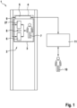
- Figure 1 shows an elevator system 1, in particular a passenger elevator system, comprising an elevator car 3 movably mounted along a roadway 2, wherein when emergency call information 100 describing an emergency call situation of the elevator system 1 is generated or present, an at least temporary wireless communication infrastructure 4 is provided within the elevator car 3 via a , in particular assigned to the elevator car 3, Communication infrastructure generation device 5 takes place. Furthermore, a communication device 6 of a user 7 located in the elevator car 3 is connected to the wireless communication infrastructure 4 provided or generated within the elevator car 3.
- the communication infrastructure generating device 5 can, as in Figure 1 shown in or on the elevator car 3 be arranged. Alternatively, the communication infrastructure generating device 5 is decoupled from the elevator car 3 or is not in direct contact with the elevator car 3 in the building (not shown) comprising the elevator system 1 in such a way that, in the event of the communication infrastructure 4 being provided and/or generated, the elevator car 3 is covered by it. For example, a communication infrastructure 4 designed as a WLAN is provided and/or generated as required by the communication infrastructure generation device 5.
- the communication infrastructure 4 can, if necessary, be generated by the communication infrastructure generation device 5 after emergency call information 100 is available or can be permanently in a fully functional state or in a standby state or sleep state. At least in a standby state that provides at least only partial functionality, it can be provided that after the emergency call information 100 is available, the communication infrastructure generating device 5 is switched, in particular automatically, to a (fully) active state. This means that an at least temporary wireless communication infrastructure 4 can be generated within the elevator car 3 via a communication infrastructure generation device 5 assigned to the elevator car 3 depending on the presence of corresponding emergency call information 100.
- An initiation structure 8 can be arranged or formed in or on, in particular within, the elevator car 3. Creating the temporary wireless communication infrastructure 4 within the Elevator car 3 can be done, for example, via the communication infrastructure generation device 5 assigned to the elevator car 3 after detection of the initiation structure 8 by the communication device 6 of the user 7 located in the elevator car 3.
- the initiation structure 8 can be designed as a 2D code (e.g. QR code) or as a bar code, which can preferably be detected via an optical detection device 12 of the communication device 6.
- the communication partner 10 can be connected to the communication infrastructure generating device 5 via a computer 11 provided at its location.
- the communication connection 9 is established via the communication device 6 of the user 7 located in the elevator car 3, which is connected to the wireless communication infrastructure 4 provided within the elevator car 3.
- the computer 11 of the communication partner 10 can be placed in the building comprising the elevator system 1 or at a location remote from the building comprising the elevator system 1.
- audio and/or video information can be sent from the user-side communication device 6 to the external communication partner 10 and/or from the external communication partner 10 to the user-side Communication device 6 are transmitted.
- audio and/or video information can be output to a display means of the computer 11 of the communication partner 10.
- Action information describing action instructions directed to the user 7 can also be transmitted to the communication device 6 of the user 7 located in the elevator car 3 via the communication connection established between the communication device 6 of the user 7 located in the elevator car 3 and the external communication partner 10. This allows the user 7 to receive action information describing action instructions addressed to him through the optical, haptic and/or acoustic perception of the output elements (e.g. the functional units 13 that can be used as output devices) of his communication device 6.
- status information describing the status of the emergency call situation in particular the status of the elimination of the emergency call situation, can be sent to the communication device via the communication connection 9 established between the communication device 6 of the user 7 located in the elevator car 3 and the external communication partner 10 6 of the user 7 located in the elevator car 3 are transmitted.
- a progress bar (not shown) can be output on a display unit 28 of the communication device 6.
- user state information describing the state of the user 7, in particular the state of health of the user 7, can be transmitted to the external communication partner 10 between the communication device 6 of the user 7 located in the elevator car 3 and the external communication partner 10.
- a catalog of questions can be communicated to the user 7, whose answers allow a conclusion to be drawn about the user status and can therefore represent user status information.
- the communication device 6 can include a detection device 12, in particular a status detection device, which allows optical, acoustic and/or haptic or tactile information to be detected and this to be transmitted as user status information to the communication partner-side computer 11.
- the detection device 12 can typically be used for other tasks sensor unit used, e.g. B.
- the communication device 6 can include at least one specific, ie optimized, status detection device, which allows e.g. B. to detect a vital parameter of the user 7 or other optical, acoustic and / or tactile abnormalities of the user 7.
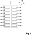
- the communication connection 9 established between the communication device 6 of the user 7 located in the elevator car 3 and the external communication partner 10 it can be provided, regardless of any operating actions by the user 7, at least one operating state of at least one functional unit 13 on the communication device side, in particular an audio and / or Video capture device to transmit control information from the external communication partner 10 to the communication device 6 of the user 7 located in the elevator car 3.
- This allows the communication partner 10 to control and/or regulate at least one functional unit 13 of the communication device 6, for example through control information generated via its computer 11.
- Functional units 13 of the communication device 6 can be, for example: a detection device 12, e.g. B. a front camera 14, a rear camera 15, a vibration or acceleration sensor 16, a microphone 17, a fingerprint scanner 18, a proximity sensor 19 (e.g. for detecting the position of an ear), a brightness sensor 20 Inclination sensor 21, a gyroscope sensor 22 or rotation sensor, a temperature sensor 23, a magnetic field sensor 24, an air pressure sensor 25 and / or a data memory 26.
- the air pressure sensor 25 can be used to determine the position of the user 7 or the elevator car 3 within the roadway 2 of the elevator system 1.
- the generation of the emergency call information 100 describing an emergency call situation of the elevator system 1 can z. B. by operating an elevator car side Actuating element 27 takes place.
- a in particular automated, downloading of an emergency situation software provided by an operator of the elevator system 1 onto the communication device 6 of the user 7 and / or a, in particular automated, activation of an emergency situation software located on the communication device 6 of the user 7.
- the emergency situation software can be stored in the data memory 27 on the communication device side.
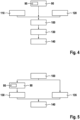
- a user can install 90 an emergency situation software 95 on the communication device 6 of the user 7 located in the elevator car 3.
- the user 7 can carry out an installation 90 of the program or the app or the emergency situation software 95 - even outside the elevator car 3.
- emergency call information 100 provided for this purpose can be generated.
- This allows emergency call information 100 generated by the user (user-generated 110).
- an emergency call situation can be recognized or emergency call information 100 can be generated by a communication device-side and/or by an elevator system-side detection device and/or by a communication partner 10; this can be done on a non-user side Generation 120 of the emergency call information 100 can be referred to.
- a browser located on the communication device 6 of the user 7 for data exchange 140.
- a link can be provided to the user 7 (e.g. in a visually perceptible form within the elevator car 3) or transmitted (e.g. via SMS).
- a browser-supported setup 135 of a communication connection 9 takes place for a data exchange 140 between the user 7 located in the elevator car and the external communication partner 10.
- the communication infrastructure 4 can be used as a, possibly encrypted, Bluetooth and/or WLAN infrastructure can be provided or generated.
- Communication infrastructure generation device 5 for an elevator system can be set up to generate a temporary wireless communication infrastructure 4 within an elevator car 3 depending on the presence of corresponding emergency call information 100.
- the communication infrastructure generation device 5 can be designed as a retrofit kit and can be retrofitted to conventional or existing elevator systems 1, in particular to existing elevator cars 3, in order to enable the expanded range of functions according to the invention.
- the communication infrastructure generating device 5 can be integrated or coupled via wired or wireless interfaces, preferably into an existing power supply system (not shown) of the elevator system 1 and/or to an existing control system (not shown) of the elevator system 1.
- the communication infrastructure generating device 5 can form a self-sufficient unit, which can be operated independently of a power supply system of the elevator system 1 and/or of a control system of the elevator system 1. In this case, the independent operability of the communication infrastructure generating device 5 can be limited in time or at least with almost no time limit.
Landscapes
- Engineering & Computer Science (AREA)
- Computer Networks & Wireless Communication (AREA)
- Signal Processing (AREA)
- Automation & Control Theory (AREA)
- Health & Medical Sciences (AREA)
- General Health & Medical Sciences (AREA)
- Medical Informatics (AREA)
- Business, Economics & Management (AREA)
- Emergency Management (AREA)
- Environmental & Geological Engineering (AREA)
- Public Health (AREA)
- Computing Systems (AREA)
- Indicating And Signalling Devices For Elevators (AREA)
- Maintenance And Inspection Apparatuses For Elevators (AREA)
Claims (11)
- Procédé d'exploitation d'un système d'ascenseur (1), en particulier d'un système d'ascenseur pour personnes, comprenant une cabine d'ascenseur (3), accessible le long d'une chaussée (2), comportant les étapes suivantes:- Générer une situation d'appel d'urgence du système d'ascenseur (1) d'information d'urgence descriptive (100);- Fournir une infrastructure de communication sans fil au moins temporaire (4) à l'intérieur de la cabine d'ascenseur (3) par l'intermédiaire d'un dispositif de génération d'infrastructure de communication associé à la cabine d'ascenseur (3) (5);- Relier un appareil de communication (6) d'un utilisateur dans la cabine d'ascenseur (3) à l'infrastructure de communication sans fil produite à l'intérieur de la cabine d'ascenseur (3) (4), et- L' infrastructure de communication sans fil au moins temporaire (4) à l'intérieur de la cabine d'ascenseur (3), par l'intermédiaire du dispositif de génération d'infrastructure de communication affecté à la cabine d'ascenseur (3) (5), produit en fonction de l'existence d'une information d'urgence (100)en ce que:
la production d'informations d'urgence décrivant une situation d'appel d'urgence de l'installation d'ascenseur (100) par:• l'actionnement d'un élément de commande côté cabine d'ascenseur (27) est effectué; ou• un dispositif d'entrée côté de l'appareil de communication a lieu; ou• une personne se trouve à l'extérieur de la cabine de l'ascenseur, ou• un ordinateur connecté à un dispositif de détection d'appel d'urgence (11) est automatisé, la cabine d'ascenseur (3) étant équipée d'une caméra capturant un intérieur de la cabine d'ascenseur (3) et qui génère automatiquement une image de cette caméra d'analyse automatique (11) en présence d'un modèle d'urgence prédéfini (100).• - Procédé selon la revendication 1, caractérisé en ce que la création de l'infrastructure temporaire de communication sans fil (4) à l'intérieur de la cabine d'ascenseur (3) par l'intermédiaire de l'équipement de génération d'infrastructure de communication affecté à la cabine d'ascenseur (3) (5), après avoir saisi une structure d'initiation disposée ou formée côté ascenseur (8), en particulier un code bar ou QR, est effectuée par l'appareil de communication (6) de l'utilisateur qui se trouve dans la cabine d'ascenseur (3) (7).
- Procédé selon la revendication 1 ou 2, caractérisé par lacréation d'une connexion de communication, notamment bidirectionnelle, entre l'appareil de communication (6) de l'utilisateur situé dans la cabine d'ascenseur (3) et un partenaire de communication externe (10) par l'intermédiaire de l'appareil de communication sans fil raccordé à l'infrastructure de communication sans fil fournie à l'intérieur de la cabine d'ascenseur (3) (6) de l'utilisateur dans la cabine d'ascenseur (3) (7).
- Procédé selon la revendication 3, caractérisé en ce que, par le biais de la connexion de communication établie (9) entre l'appareil de communication (6) de l'utilisateur qui se trouve dans la cabine (3) et le partenaire de communication externe (10) les informations audio et/ou vidéo sont transmises de l'appareil de communication côté utilisateur (6) au partenaire de communication externe (10) et/ou du partenaire de communication externe (10) à l'appareil de communication côté utilisateur (6).
- Procédé selon la revendication 3 ou 4, caractérisé en ce que, par le biais de la connexion de communication établie (9) entre l'appareil de communication (6) de l'utilisateur qui se trouve dans la cabine (3) et le partenaire externe de communication (10) à l'utilisateur (7), des informations d'action descriptives sont transmises à l'appareil de communication (6) de l'utilisateur qui se trouve dans la cabine d'ascenseur (3) (7).
- Procédé selon l'une des revendications 3 à 5, caractérisé en ce que, par le biais de la connexion de communication établie (9) entre l'appareil de communication (6) de l'utilisateur dans la cabine d'ascenseur (3) et le partenaire de communication externe (10) adressé à l'utilisateur (7), le statut de la situation d'appel d'urgence, en particulier le statut de la réparation de la situation d'urgence, est transmis à l'appareil de communication (6) de l'utilisateur dans la cabine d'ascenseur (3) (7).
- Procédé selon l'une des revendications 3 à 6, caractérisé en ce que, par le biais de la connexion de communication établie (9) entre l'appareil de communication (6) de l'utilisateur dans la cabine (3) et le partenaire de communication externe (10), l'état de l'utilisateur (7), en particulier l'état de santé de l'utilisateur (7), est transmis au partenaire externe de communication (10).
- Procédé selon l'une des revendications 3 à 7, caractérisé en ce que, par le biais de la connexion de communication établie (9) entre l'appareil de communication (6) de l'utilisateur qui se trouve dans la cabine (3) et le partenaire de communication externe (10), indépendamment des opérations de l'utilisateur (7), au moins un état de fonctionnement au moins d'une unité fonctionnelle de l'appareil de communication (13), en particulier un dispositif d'acquisition audio et/ou vidéo, est transmis par le partenaire de communication externe (10) à l'appareil de communication (6) de l'utilisateur situé dans la cabine d'ascenseur (3) (7).
- Procédé selon l'une des revendications précédentes, caractérisé en ce que,après connexion de l'appareil de communication (6) de l'utilisateur dans la cabine d'ascenseur (3) (7) avec l'infrastructure de communication sans fil fournie ou produite à l'intérieur de la cabine (3), il est procédé, notamment, au téléchargement automatisé d'un logiciel d'urgence (95) mis à disposition par un opérateur de l'ascenseur (95) sur l'appareil de communication (6) de l'utilisateur (7) et/ou à l'activation, notamment automatisée, d'un logiciel d'urgence (95) situé sur l'appareil de communication (6) de l'utilisateur (7) et/ou d'un fonctionnement côté appareil de communication d'un logiciel d'urgence fondé sur un navigateur (95).
- Procédé selon la revendication 9, caractérisé en ce que le logiciel d'urgence (95) initie une consultation de la situation d'appel d'urgence et/ou de l'état de l'utilisateur dans la cabine d'ascenseur (3) (7) et/ou l'envoi d'instructions d'action aux informations d'instruction d'action concernant l'utilisateur situé dans la cabine d'ascenseur (3).
- Procédé selon l'une des revendications précédentes, caractérisé en ce quel'infrastructure de communication (4) est fournie ou produite en tant que connexion radio, le cas échéant cryptée, l'infrastructure de communication (4) comprend notamment une infrastructure Wi-Fi et/ou une infrastructure Bluetooth et/ou une infrastructure RFID et/ou une infrastructure de communication en champ proche (NFC) et/ou une infrastructure de télécommunications mobiles universelles (UMTS) et/ou une infrastructure de réseau mobile de nouvelle génération (NGMN) et/ou une infrastructure de réseau mobile.
Applications Claiming Priority (1)
| Application Number | Priority Date | Filing Date | Title |
|---|---|---|---|
| DE102019113558.3A DE102019113558A1 (de) | 2019-05-21 | 2019-05-21 | Verfahren zum Betrieb einer Aufzuganlage |
Publications (2)
| Publication Number | Publication Date |
|---|---|
| EP3789331A1 EP3789331A1 (fr) | 2021-03-10 |
| EP3789331B1 true EP3789331B1 (fr) | 2024-01-24 |
Family
ID=70736734
Family Applications (1)
| Application Number | Title | Priority Date | Filing Date |
|---|---|---|---|
| EP20174695.5A Active EP3789331B1 (fr) | 2019-05-21 | 2020-05-14 | Procédé de fonctionnement d'un système d'ascenseur |
Country Status (2)
| Country | Link |
|---|---|
| EP (1) | EP3789331B1 (fr) |
| DE (1) | DE102019113558A1 (fr) |
Families Citing this family (2)
| Publication number | Priority date | Publication date | Assignee | Title |
|---|---|---|---|---|
| DE102023000557A1 (de) * | 2023-02-20 | 2024-08-22 | Michael Langer | Lokale Notrufeinheit mit einer Künstlichen Intelligenz (KI) |
| DE102023002994A1 (de) * | 2023-07-21 | 2025-01-23 | Michael Langer | Akustische Notruferkennung |
Citations (8)
| Publication number | Priority date | Publication date | Assignee | Title |
|---|---|---|---|---|
| WO2007043557A1 (fr) | 2005-10-11 | 2007-04-19 | Toshiba Elevator Kabushiki Kaisha | Système et procédé de surveillance à distance d’ascenceur et cachet du code |
| JP2009120291A (ja) | 2007-11-13 | 2009-06-04 | Hitachi Building Systems Co Ltd | エレベータの防災システム |
| WO2011069679A1 (fr) | 2009-12-11 | 2011-06-16 | Telegärtner Elektronik GmbH | Carte sim et module d'appel d'urgence |
| JP2012006753A (ja) | 2010-06-28 | 2012-01-12 | Mitsubishi Electric Corp | エレベータの非常連絡システム |
| JP2015202916A (ja) | 2014-04-11 | 2015-11-16 | 株式会社日立製作所 | エレベータの非常通報システム |
| CN106006273A (zh) | 2016-07-29 | 2016-10-12 | 浙江新再灵科技股份有限公司 | 一种电梯状态监控显示系统 |
| JP2018083691A (ja) | 2016-11-24 | 2018-05-31 | 東芝エレベータ株式会社 | エレベータシステム |
| JP2018095402A (ja) | 2016-12-13 | 2018-06-21 | 東芝エレベータ株式会社 | エレベータの制御装置 |
-
2019
- 2019-05-21 DE DE102019113558.3A patent/DE102019113558A1/de active Pending
-
2020
- 2020-05-14 EP EP20174695.5A patent/EP3789331B1/fr active Active
Patent Citations (8)
| Publication number | Priority date | Publication date | Assignee | Title |
|---|---|---|---|---|
| WO2007043557A1 (fr) | 2005-10-11 | 2007-04-19 | Toshiba Elevator Kabushiki Kaisha | Système et procédé de surveillance à distance d’ascenceur et cachet du code |
| JP2009120291A (ja) | 2007-11-13 | 2009-06-04 | Hitachi Building Systems Co Ltd | エレベータの防災システム |
| WO2011069679A1 (fr) | 2009-12-11 | 2011-06-16 | Telegärtner Elektronik GmbH | Carte sim et module d'appel d'urgence |
| JP2012006753A (ja) | 2010-06-28 | 2012-01-12 | Mitsubishi Electric Corp | エレベータの非常連絡システム |
| JP2015202916A (ja) | 2014-04-11 | 2015-11-16 | 株式会社日立製作所 | エレベータの非常通報システム |
| CN106006273A (zh) | 2016-07-29 | 2016-10-12 | 浙江新再灵科技股份有限公司 | 一种电梯状态监控显示系统 |
| JP2018083691A (ja) | 2016-11-24 | 2018-05-31 | 東芝エレベータ株式会社 | エレベータシステム |
| JP2018095402A (ja) | 2016-12-13 | 2018-06-21 | 東芝エレベータ株式会社 | エレベータの制御装置 |
Non-Patent Citations (2)
| Title |
|---|
| ANONYMOUS: "Sicherheitsregeln für die Konstruktion und den Einbau von Aufzügen - Besondere Anwendungen für Personen- und Lastenaufzüge - Teil 73: Verhalten von Aufzügen im Brandfall; Deutsche Fassung", DEUTSCHE NORM DIN 81-73, 1 June 2016 (2016-06-01), pages 1 - 18, XP093234995 |
| ZHANG ZHANG , KAIQI HUANG: "Intelligent Visual Surveillance", 1 January 2016, SPRINGER , ISBN: 978-981-10-3475-6, article ZHU YUJIE , ZENGFU WANG: "Real-Time Abnormal Behavior Detection in Elevator", pages: 154 - 161, XP093234990, DOI: 10.1007/978-981-10-3476-3 |
Also Published As
| Publication number | Publication date |
|---|---|
| DE102019113558A1 (de) | 2020-11-26 |
| EP3789331A1 (fr) | 2021-03-10 |
Similar Documents
| Publication | Publication Date | Title |
|---|---|---|
| EP3010213B1 (fr) | Envoi automatique d'un message d'urgence en cas d`un appel d`urgence | |
| DE102012205162A1 (de) | Beobachtung und/oder Bedienung eines Sport- und/oder Rehabilitationsgerätes | |
| WO2009056525A1 (fr) | Procédé pour déterminer un appel de destination en vue de l'utilisation d'un ascenseur et ascenseur correspondant | |
| WO2011073212A1 (fr) | Procédé de télédiagnostic d'une installation d'ascenseur et installation d'ascenseur pour la mise en œuvre du procédé | |
| DE10163213A1 (de) | Verfahren zum Betrieb eines Spracherkennungssystems | |
| EP3789331B1 (fr) | Procédé de fonctionnement d'un système d'ascenseur | |
| DE10009882A1 (de) | Mobiles Telekommunikations-Endgerät, insbesondere Mobiltelefon | |
| DE112018000702T5 (de) | Robotersystem und roboterdialogverfahren | |
| EP1688086A1 (fr) | Dispositif destiné à la surveillance de valeurs vitales de personnes âgées | |
| EP3646127B1 (fr) | Commande spéciale pour fauteuil roulant | |
| EP3473181B1 (fr) | Procédé de fonctionnement d'un dispositif d'acquisition d'images médicales, dispositif d'acquisition d'images, programme informatique et support d'informations lisible électroniquement | |
| EP2922039B1 (fr) | Système lumineux de secours et procédé correspondant | |
| EP3433776B1 (fr) | Commande à distance des messages d'un appareil de dialyse | |
| DE102006058552B4 (de) | Empfangssystem | |
| DE102013224279A1 (de) | Verfahren und System zum Bereitstellen eines Assistenzvorschlages für einen Benutzer eines Kraftfahrzeuges | |
| EP4425957A1 (fr) | Procédé de fonctionnement d'un dispositif auditif | |
| DE102023201075B3 (de) | Verfahren zum Betrieb eines Hörinstruments und Hörsystem mit einem solchen Hörinstrument | |
| WO2021160576A1 (fr) | Procédé, dispositif et système de surveillance à distance d'un dispositif médical | |
| EP2091023B1 (fr) | Procédé de génération d'un signal d'information lors d'un souhait d'accès et dispositif d'exécution du procédé | |
| DE19839550B4 (de) | Verfahren und Vorrichtung zur Abgabe eines Notrufs | |
| DE102007032610A1 (de) | Verfahren zur Fernüberwachung des medizinischen Zustandes eines Nutzers, System und Vorrichtung dafür | |
| DE102017117265A1 (de) | Verfahren zur Assistenz eines Nutzers | |
| EP4270347A2 (fr) | Système de sécurité | |
| EP4387197A1 (fr) | Système de communication pour communication basée sur texte | |
| EP2875628B1 (fr) | Procede et dispositif de communication |
Legal Events
| Date | Code | Title | Description |
|---|---|---|---|
| PUAI | Public reference made under article 153(3) epc to a published international application that has entered the european phase |
Free format text: ORIGINAL CODE: 0009012 |
|
| STAA | Information on the status of an ep patent application or granted ep patent |
Free format text: STATUS: THE APPLICATION HAS BEEN PUBLISHED |
|
| AK | Designated contracting states |
Kind code of ref document: A1 Designated state(s): AL AT BE BG CH CY CZ DE DK EE ES FI FR GB GR HR HU IE IS IT LI LT LU LV MC MK MT NL NO PL PT RO RS SE SI SK SM TR |
|
| AX | Request for extension of the european patent |
Extension state: BA ME |
|
| STAA | Information on the status of an ep patent application or granted ep patent |
Free format text: STATUS: REQUEST FOR EXAMINATION WAS MADE |
|
| 17P | Request for examination filed |
Effective date: 20210907 |
|
| RBV | Designated contracting states (corrected) |
Designated state(s): AL AT BE BG CH CY CZ DE DK EE ES FI FR GB GR HR HU IE IS IT LI LT LU LV MC MK MT NL NO PL PT RO RS SE SI SK SM TR |
|
| STAA | Information on the status of an ep patent application or granted ep patent |
Free format text: STATUS: EXAMINATION IS IN PROGRESS |
|
| 17Q | First examination report despatched |
Effective date: 20220908 |
|
| GRAP | Despatch of communication of intention to grant a patent |
Free format text: ORIGINAL CODE: EPIDOSNIGR1 |
|
| STAA | Information on the status of an ep patent application or granted ep patent |
Free format text: STATUS: GRANT OF PATENT IS INTENDED |
|
| INTG | Intention to grant announced |
Effective date: 20230825 |
|
| GRAS | Grant fee paid |
Free format text: ORIGINAL CODE: EPIDOSNIGR3 |
|
| GRAA | (expected) grant |
Free format text: ORIGINAL CODE: 0009210 |
|
| STAA | Information on the status of an ep patent application or granted ep patent |
Free format text: STATUS: THE PATENT HAS BEEN GRANTED |
|
| AK | Designated contracting states |
Kind code of ref document: B1 Designated state(s): AL AT BE BG CH CY CZ DE DK EE ES FI FR GB GR HR HU IE IS IT LI LT LU LV MC MK MT NL NO PL PT RO RS SE SI SK SM TR |
|
| REG | Reference to a national code |
Ref country code: GB Ref legal event code: FG4D Free format text: NOT ENGLISH |
|
| REG | Reference to a national code |
Ref country code: CH Ref legal event code: EP |
|
| REG | Reference to a national code |
Ref country code: DE Ref legal event code: R096 Ref document number: 502020006802 Country of ref document: DE |
|
| REG | Reference to a national code |
Ref country code: IE Ref legal event code: FG4D Free format text: LANGUAGE OF EP DOCUMENT: GERMAN |
|
| P01 | Opt-out of the competence of the unified patent court (upc) registered |
Effective date: 20240220 |
|
| REG | Reference to a national code |
Ref country code: SE Ref legal event code: TRGR |
|
| REG | Reference to a national code |
Ref country code: LT Ref legal event code: MG9D |
|
| REG | Reference to a national code |
Ref country code: NL Ref legal event code: MP Effective date: 20240124 |
|
| PG25 | Lapsed in a contracting state [announced via postgrant information from national office to epo] |
Ref country code: NL Free format text: LAPSE BECAUSE OF FAILURE TO SUBMIT A TRANSLATION OF THE DESCRIPTION OR TO PAY THE FEE WITHIN THE PRESCRIBED TIME-LIMIT Effective date: 20240124 |
|
| PG25 | Lapsed in a contracting state [announced via postgrant information from national office to epo] |
Ref country code: NL Free format text: LAPSE BECAUSE OF FAILURE TO SUBMIT A TRANSLATION OF THE DESCRIPTION OR TO PAY THE FEE WITHIN THE PRESCRIBED TIME-LIMIT Effective date: 20240124 |
|
| PG25 | Lapsed in a contracting state [announced via postgrant information from national office to epo] |
Ref country code: IS Free format text: LAPSE BECAUSE OF FAILURE TO SUBMIT A TRANSLATION OF THE DESCRIPTION OR TO PAY THE FEE WITHIN THE PRESCRIBED TIME-LIMIT Effective date: 20240524 |
|
| PG25 | Lapsed in a contracting state [announced via postgrant information from national office to epo] |
Ref country code: LT Free format text: LAPSE BECAUSE OF FAILURE TO SUBMIT A TRANSLATION OF THE DESCRIPTION OR TO PAY THE FEE WITHIN THE PRESCRIBED TIME-LIMIT Effective date: 20240124 |
|
| PG25 | Lapsed in a contracting state [announced via postgrant information from national office to epo] |
Ref country code: GR Free format text: LAPSE BECAUSE OF FAILURE TO SUBMIT A TRANSLATION OF THE DESCRIPTION OR TO PAY THE FEE WITHIN THE PRESCRIBED TIME-LIMIT Effective date: 20240425 |
|
| PG25 | Lapsed in a contracting state [announced via postgrant information from national office to epo] |
Ref country code: RS Free format text: LAPSE BECAUSE OF FAILURE TO SUBMIT A TRANSLATION OF THE DESCRIPTION OR TO PAY THE FEE WITHIN THE PRESCRIBED TIME-LIMIT Effective date: 20240424 Ref country code: HR Free format text: LAPSE BECAUSE OF FAILURE TO SUBMIT A TRANSLATION OF THE DESCRIPTION OR TO PAY THE FEE WITHIN THE PRESCRIBED TIME-LIMIT Effective date: 20240124 |
|
| PG25 | Lapsed in a contracting state [announced via postgrant information from national office to epo] |
Ref country code: ES Free format text: LAPSE BECAUSE OF FAILURE TO SUBMIT A TRANSLATION OF THE DESCRIPTION OR TO PAY THE FEE WITHIN THE PRESCRIBED TIME-LIMIT Effective date: 20240124 |
|
| PG25 | Lapsed in a contracting state [announced via postgrant information from national office to epo] |
Ref country code: RS Free format text: LAPSE BECAUSE OF FAILURE TO SUBMIT A TRANSLATION OF THE DESCRIPTION OR TO PAY THE FEE WITHIN THE PRESCRIBED TIME-LIMIT Effective date: 20240424 Ref country code: NO Free format text: LAPSE BECAUSE OF FAILURE TO SUBMIT A TRANSLATION OF THE DESCRIPTION OR TO PAY THE FEE WITHIN THE PRESCRIBED TIME-LIMIT Effective date: 20240424 Ref country code: LT Free format text: LAPSE BECAUSE OF FAILURE TO SUBMIT A TRANSLATION OF THE DESCRIPTION OR TO PAY THE FEE WITHIN THE PRESCRIBED TIME-LIMIT Effective date: 20240124 Ref country code: IS Free format text: LAPSE BECAUSE OF FAILURE TO SUBMIT A TRANSLATION OF THE DESCRIPTION OR TO PAY THE FEE WITHIN THE PRESCRIBED TIME-LIMIT Effective date: 20240524 Ref country code: HR Free format text: LAPSE BECAUSE OF FAILURE TO SUBMIT A TRANSLATION OF THE DESCRIPTION OR TO PAY THE FEE WITHIN THE PRESCRIBED TIME-LIMIT Effective date: 20240124 Ref country code: GR Free format text: LAPSE BECAUSE OF FAILURE TO SUBMIT A TRANSLATION OF THE DESCRIPTION OR TO PAY THE FEE WITHIN THE PRESCRIBED TIME-LIMIT Effective date: 20240425 Ref country code: FI Free format text: LAPSE BECAUSE OF FAILURE TO SUBMIT A TRANSLATION OF THE DESCRIPTION OR TO PAY THE FEE WITHIN THE PRESCRIBED TIME-LIMIT Effective date: 20240124 Ref country code: ES Free format text: LAPSE BECAUSE OF FAILURE TO SUBMIT A TRANSLATION OF THE DESCRIPTION OR TO PAY THE FEE WITHIN THE PRESCRIBED TIME-LIMIT Effective date: 20240124 Ref country code: BG Free format text: LAPSE BECAUSE OF FAILURE TO SUBMIT A TRANSLATION OF THE DESCRIPTION OR TO PAY THE FEE WITHIN THE PRESCRIBED TIME-LIMIT Effective date: 20240124 |
|
| PG25 | Lapsed in a contracting state [announced via postgrant information from national office to epo] |
Ref country code: PT Free format text: LAPSE BECAUSE OF FAILURE TO SUBMIT A TRANSLATION OF THE DESCRIPTION OR TO PAY THE FEE WITHIN THE PRESCRIBED TIME-LIMIT Effective date: 20240524 Ref country code: PL Free format text: LAPSE BECAUSE OF FAILURE TO SUBMIT A TRANSLATION OF THE DESCRIPTION OR TO PAY THE FEE WITHIN THE PRESCRIBED TIME-LIMIT Effective date: 20240124 |
|
| PG25 | Lapsed in a contracting state [announced via postgrant information from national office to epo] |
Ref country code: PT Free format text: LAPSE BECAUSE OF FAILURE TO SUBMIT A TRANSLATION OF THE DESCRIPTION OR TO PAY THE FEE WITHIN THE PRESCRIBED TIME-LIMIT Effective date: 20240524 Ref country code: PL Free format text: LAPSE BECAUSE OF FAILURE TO SUBMIT A TRANSLATION OF THE DESCRIPTION OR TO PAY THE FEE WITHIN THE PRESCRIBED TIME-LIMIT Effective date: 20240124 Ref country code: LV Free format text: LAPSE BECAUSE OF FAILURE TO SUBMIT A TRANSLATION OF THE DESCRIPTION OR TO PAY THE FEE WITHIN THE PRESCRIBED TIME-LIMIT Effective date: 20240124 |
|
| PG25 | Lapsed in a contracting state [announced via postgrant information from national office to epo] |
Ref country code: DK Free format text: LAPSE BECAUSE OF FAILURE TO SUBMIT A TRANSLATION OF THE DESCRIPTION OR TO PAY THE FEE WITHIN THE PRESCRIBED TIME-LIMIT Effective date: 20240124 |
|
| PG25 | Lapsed in a contracting state [announced via postgrant information from national office to epo] |
Ref country code: SM Free format text: LAPSE BECAUSE OF FAILURE TO SUBMIT A TRANSLATION OF THE DESCRIPTION OR TO PAY THE FEE WITHIN THE PRESCRIBED TIME-LIMIT Effective date: 20240124 |
|
| PG25 | Lapsed in a contracting state [announced via postgrant information from national office to epo] |
Ref country code: EE Free format text: LAPSE BECAUSE OF FAILURE TO SUBMIT A TRANSLATION OF THE DESCRIPTION OR TO PAY THE FEE WITHIN THE PRESCRIBED TIME-LIMIT Effective date: 20240124 |
|
| REG | Reference to a national code |
Ref country code: DE Ref legal event code: R026 Ref document number: 502020006802 Country of ref document: DE |
|
| PG25 | Lapsed in a contracting state [announced via postgrant information from national office to epo] |
Ref country code: SK Free format text: LAPSE BECAUSE OF FAILURE TO SUBMIT A TRANSLATION OF THE DESCRIPTION OR TO PAY THE FEE WITHIN THE PRESCRIBED TIME-LIMIT Effective date: 20240124 |
|
| PG25 | Lapsed in a contracting state [announced via postgrant information from national office to epo] |
Ref country code: SM Free format text: LAPSE BECAUSE OF FAILURE TO SUBMIT A TRANSLATION OF THE DESCRIPTION OR TO PAY THE FEE WITHIN THE PRESCRIBED TIME-LIMIT Effective date: 20240124 Ref country code: SK Free format text: LAPSE BECAUSE OF FAILURE TO SUBMIT A TRANSLATION OF THE DESCRIPTION OR TO PAY THE FEE WITHIN THE PRESCRIBED TIME-LIMIT Effective date: 20240124 Ref country code: EE Free format text: LAPSE BECAUSE OF FAILURE TO SUBMIT A TRANSLATION OF THE DESCRIPTION OR TO PAY THE FEE WITHIN THE PRESCRIBED TIME-LIMIT Effective date: 20240124 Ref country code: DK Free format text: LAPSE BECAUSE OF FAILURE TO SUBMIT A TRANSLATION OF THE DESCRIPTION OR TO PAY THE FEE WITHIN THE PRESCRIBED TIME-LIMIT Effective date: 20240124 |
|
| PLBI | Opposition filed |
Free format text: ORIGINAL CODE: 0009260 |
|
| PLAX | Notice of opposition and request to file observation + time limit sent |
Free format text: ORIGINAL CODE: EPIDOSNOBS2 |
|
| 26 | Opposition filed |
Opponent name: OTIS ELEVATOR COMPANY Effective date: 20241024 |
|
| PG25 | Lapsed in a contracting state [announced via postgrant information from national office to epo] |
Ref country code: IT Free format text: LAPSE BECAUSE OF FAILURE TO SUBMIT A TRANSLATION OF THE DESCRIPTION OR TO PAY THE FEE WITHIN THE PRESCRIBED TIME-LIMIT Effective date: 20240124 |
|
| PG25 | Lapsed in a contracting state [announced via postgrant information from national office to epo] |
Ref country code: IT Free format text: LAPSE BECAUSE OF FAILURE TO SUBMIT A TRANSLATION OF THE DESCRIPTION OR TO PAY THE FEE WITHIN THE PRESCRIBED TIME-LIMIT Effective date: 20240124 |
|
| PG25 | Lapsed in a contracting state [announced via postgrant information from national office to epo] |
Ref country code: MC Free format text: LAPSE BECAUSE OF FAILURE TO SUBMIT A TRANSLATION OF THE DESCRIPTION OR TO PAY THE FEE WITHIN THE PRESCRIBED TIME-LIMIT Effective date: 20240124 |
|
| PG25 | Lapsed in a contracting state [announced via postgrant information from national office to epo] |
Ref country code: LU Free format text: LAPSE BECAUSE OF NON-PAYMENT OF DUE FEES Effective date: 20240514 |
|
| GBPC | Gb: european patent ceased through non-payment of renewal fee |
Effective date: 20240514 |
|
| PG25 | Lapsed in a contracting state [announced via postgrant information from national office to epo] |
Ref country code: MC Free format text: LAPSE BECAUSE OF FAILURE TO SUBMIT A TRANSLATION OF THE DESCRIPTION OR TO PAY THE FEE WITHIN THE PRESCRIBED TIME-LIMIT Effective date: 20240124 Ref country code: LU Free format text: LAPSE BECAUSE OF NON-PAYMENT OF DUE FEES Effective date: 20240514 |
|
| REG | Reference to a national code |
Ref country code: BE Ref legal event code: MM Effective date: 20240531 |
|
| PLBB | Reply of patent proprietor to notice(s) of opposition received |
Free format text: ORIGINAL CODE: EPIDOSNOBS3 |
|
| PG25 | Lapsed in a contracting state [announced via postgrant information from national office to epo] |
Ref country code: IE Free format text: LAPSE BECAUSE OF NON-PAYMENT OF DUE FEES Effective date: 20240514 |
|
| PG25 | Lapsed in a contracting state [announced via postgrant information from national office to epo] |
Ref country code: SI Free format text: LAPSE BECAUSE OF FAILURE TO SUBMIT A TRANSLATION OF THE DESCRIPTION OR TO PAY THE FEE WITHIN THE PRESCRIBED TIME-LIMIT Effective date: 20240124 Ref country code: BE Free format text: LAPSE BECAUSE OF NON-PAYMENT OF DUE FEES Effective date: 20240531 |
|
| PG25 | Lapsed in a contracting state [announced via postgrant information from national office to epo] |
Ref country code: GB Free format text: LAPSE BECAUSE OF NON-PAYMENT OF DUE FEES Effective date: 20240514 |
|
| PGFP | Annual fee paid to national office [announced via postgrant information from national office to epo] |
Ref country code: DE Payment date: 20250520 Year of fee payment: 6 |
|
| PGFP | Annual fee paid to national office [announced via postgrant information from national office to epo] |
Ref country code: FR Payment date: 20250523 Year of fee payment: 6 |
|
| PGFP | Annual fee paid to national office [announced via postgrant information from national office to epo] |
Ref country code: CH Payment date: 20250601 Year of fee payment: 6 |
|
| PGFP | Annual fee paid to national office [announced via postgrant information from national office to epo] |
Ref country code: AT Payment date: 20250519 Year of fee payment: 6 |
|
| PGFP | Annual fee paid to national office [announced via postgrant information from national office to epo] |
Ref country code: CZ Payment date: 20250430 Year of fee payment: 6 |
|
| PGFP | Annual fee paid to national office [announced via postgrant information from national office to epo] |
Ref country code: SE Payment date: 20250522 Year of fee payment: 6 |
|
| PG25 | Lapsed in a contracting state [announced via postgrant information from national office to epo] |
Ref country code: RO Free format text: LAPSE BECAUSE OF FAILURE TO SUBMIT A TRANSLATION OF THE DESCRIPTION OR TO PAY THE FEE WITHIN THE PRESCRIBED TIME-LIMIT Effective date: 20240124 |
|
| PG25 | Lapsed in a contracting state [announced via postgrant information from national office to epo] |
Ref country code: CY Free format text: LAPSE BECAUSE OF FAILURE TO SUBMIT A TRANSLATION OF THE DESCRIPTION OR TO PAY THE FEE WITHIN THE PRESCRIBED TIME-LIMIT; INVALID AB INITIO Effective date: 20200514 |
|
| PG25 | Lapsed in a contracting state [announced via postgrant information from national office to epo] |
Ref country code: HU Free format text: LAPSE BECAUSE OF FAILURE TO SUBMIT A TRANSLATION OF THE DESCRIPTION OR TO PAY THE FEE WITHIN THE PRESCRIBED TIME-LIMIT; INVALID AB INITIO Effective date: 20200514 |