EP3789330A1 - Dispositif et procédé de transport intermittent d'une bande de matériau le long d'une direction de transport et de coupe de la bande de matériau - Google Patents
Dispositif et procédé de transport intermittent d'une bande de matériau le long d'une direction de transport et de coupe de la bande de matériau Download PDFInfo
- Publication number
- EP3789330A1 EP3789330A1 EP20188017.6A EP20188017A EP3789330A1 EP 3789330 A1 EP3789330 A1 EP 3789330A1 EP 20188017 A EP20188017 A EP 20188017A EP 3789330 A1 EP3789330 A1 EP 3789330A1
- Authority
- EP
- European Patent Office
- Prior art keywords
- web
- conveying direction
- movement
- support
- pressure
- Prior art date
- Legal status (The legal status is an assumption and is not a legal conclusion. Google has not performed a legal analysis and makes no representation as to the accuracy of the status listed.)
- Pending
Links
Images
Classifications
-
- B—PERFORMING OPERATIONS; TRANSPORTING
- B65—CONVEYING; PACKING; STORING; HANDLING THIN OR FILAMENTARY MATERIAL
- B65H—HANDLING THIN OR FILAMENTARY MATERIAL, e.g. SHEETS, WEBS, CABLES
- B65H35/00—Delivering articles from cutting or line-perforating machines; Article or web delivery apparatus incorporating cutting or line-perforating devices, e.g. adhesive tape dispensers
- B65H35/04—Delivering articles from cutting or line-perforating machines; Article or web delivery apparatus incorporating cutting or line-perforating devices, e.g. adhesive tape dispensers from or with transverse cutters or perforators
- B65H35/06—Delivering articles from cutting or line-perforating machines; Article or web delivery apparatus incorporating cutting or line-perforating devices, e.g. adhesive tape dispensers from or with transverse cutters or perforators from or with blade, e.g. shear-blade, cutters or perforators
-
- B—PERFORMING OPERATIONS; TRANSPORTING
- B26—HAND CUTTING TOOLS; CUTTING; SEVERING
- B26D—CUTTING; DETAILS COMMON TO MACHINES FOR PERFORATING, PUNCHING, CUTTING-OUT, STAMPING-OUT OR SEVERING
- B26D7/00—Details of apparatus for cutting, cutting-out, stamping-out, punching, perforating, or severing by means other than cutting
- B26D7/01—Means for holding or positioning work
- B26D7/02—Means for holding or positioning work with clamping means
- B26D7/025—Means for holding or positioning work with clamping means acting upon planar surfaces
-
- B—PERFORMING OPERATIONS; TRANSPORTING
- B26—HAND CUTTING TOOLS; CUTTING; SEVERING
- B26D—CUTTING; DETAILS COMMON TO MACHINES FOR PERFORATING, PUNCHING, CUTTING-OUT, STAMPING-OUT OR SEVERING
- B26D7/00—Details of apparatus for cutting, cutting-out, stamping-out, punching, perforating, or severing by means other than cutting
- B26D7/27—Means for performing other operations combined with cutting
- B26D7/32—Means for performing other operations combined with cutting for conveying or stacking cut product
-
- B—PERFORMING OPERATIONS; TRANSPORTING
- B65—CONVEYING; PACKING; STORING; HANDLING THIN OR FILAMENTARY MATERIAL
- B65H—HANDLING THIN OR FILAMENTARY MATERIAL, e.g. SHEETS, WEBS, CABLES
- B65H2301/00—Handling processes for sheets or webs
- B65H2301/40—Type of handling process
- B65H2301/44—Moving, forwarding, guiding material
- B65H2301/449—Features of movement or transforming movement of handled material
- B65H2301/4493—Features of movement or transforming movement of handled material intermittent
Definitions
- a device and a method for intermittently conveying a web of material along a conveying direction and for cutting the web of material are described here.
- the details of this apparatus and method are defined in the claims; The description and the drawing also contain relevant information on the device and the mode of operation as well as on variants.
- the device comprises three conveyor units located one behind the other in the conveying direction.
- the first conveyor unit has a pair of rollers
- the second and the third conveyor unit each have a conveyor roller and resiliently mounted rollers in order to guide the material web between the conveyor roller and the rollers.
- Between the second and the third conveyor unit there is a pair of fly knives for cross-cutting the web of material.
- the second and the third conveyor unit operate at an increased speed. The material web is transported through with a slip between the conveyor roller on the one hand and the rollers on the other.
- the web of material is guided on a table above which a hold-down device is located.
- the table In order to cut a sheet from the material web, the table is swiveled upwards - driven by a coupling - so that the material web is clamped between the table and the hold-down device. In this state, the web accumulates between the first conveyor unit and the hold-down device.
- the table is lowered again so that the material web is released again and the cut sheet is fed to a tray by the third conveyor unit.
- the material web is guided on air-blown floating bars to prevent static charging of the cut sheets and to ensure that the sheets are deposited without any problems.
- the web of material is jammed in front of the pair of fly knives, which causes the web of material to sag to a greater or lesser extent.
- the jam is cleared by the second conveyor unit.
- the web of material in front of the pair of fly knives is continuously loosened and tensioned again alternately. This makes it difficult to precisely set a desired length of a sheet to be cut off.
- the table is swiveled up to clamp the material web with the aid of the coupling via a crankshaft and connecting rods. Precise setting of a desired length of a sheet to be cut is also made more difficult because of the play which is inevitably present here and which is not negligible.
- the object is therefore to provide a corresponding device and a corresponding method which - even for thin materials - enables the length of a sheet to be cut to be adjusted particularly precisely.
- a device for intermittently conveying a web of material along a conveying direction and for cutting the web of material, in particular into pieces of a length to be specified.
- the device has a cutting device for cutting the material web at an angle transverse to the conveying direction and a conveying device for conveying the material web in the conveying direction.
- the conveying device comprises a support for the material web, as well as a pressure and movement device for producing and releasing a pressure with which the material web is pushed against the support and for generating a movement of the material web relative to the support in the conveying direction.
- the conveying device is designed and set up for this purpose, the pressure and movement device for producing the pressure starting from a starting position to move in the direction of the support and then - with at least partial maintenance of the pressure - by means of a movement of the pressure and movement device in the conveying direction to a front end position to cause the movement of the web relative to the support in the conveying direction.
- a starting point for the movement of the material web can be determined particularly precisely.
- a slippage between the pressure and movement device and the material web can be prevented reliably and easily. In this way, the end point of the movement of the material web can also be determined particularly precisely.
- the variant described enables reliable conveyance of a web of material whose material thickness is particularly small.
- material webs made of plastic polymers, polycarbonates, polyesters, polyurethanes, etc.
- material thicknesses of about 100 ⁇ m or about 50 ⁇ m are conveyed reliably and precisely and can be cut into pieces with high dimensional accuracy in the conveying direction .
- the path length of the movement of the pressure and movement device can be adjusted in the conveying direction.
- the web of material can be conveyed to the desired extent and cut off particularly precisely with the cutting device at a desired predetermined point to form a piece of predetermined length or a sheet.
- the position of the start position and / or the position of the front end position of the pressure and movement device can be designed to be adjustable relative to the support.
- the movement of the pressure and movement device in the conveying direction enables the material web to be conveyed without the formation of a jam. In this way, sagging of the material web or the formation of waves can be reliably prevented.
- the web can be conveyed in a flat state.
- the conveying device is designed in such a way that when the material web moves relative to the support in the conveying direction, the material web at least partially adheres to the pressure and movement device.
- the pressure and movement device has a contact surface for the material web, which consists of a first material
- the support has a contact surface or bearing surface for the material web, which consists of a second material, the first material having a greater static coefficient of friction than the second material compared to a material of the material web, for example plastic.
- the contact surface of the pressure and movement device can be designed to be rougher than the contact surface of the support.
- the conveying device has an adhesion promoter, by means of which, when the material web moves relative to the support in the conveying direction, the material web at least partially adheres to the printing and movement device.
- the adhesion promoter can be formed, for example, by structuring the contact surface of the pressure and movement device.
- the conveying device can be designed in such a way that when the web of material is moved relative to the support in the conveying direction, the web of material adheres to the printing and moving device.
- the pressure and movement device has a pressure surface for bearing against the material web, which extends transversely to the conveying direction and which, for example, at least in sections covers the width of the material web or the entire width of the material web.
- the pressure surface can also have several segments that are spaced apart from one another. This enables the printing and movement device to adhere particularly well to the web of material.
- the pressure surface extends transversely to the conveying direction on both sides beyond the support.
- the pressure surface is preferably made of a material that has particularly good adhesive properties, such as rubber.
- the pressure and movement device has, at least in a first approximation, the shape of a bar.
- the main axis defined by the bar shape is oriented transversely, in particular 90 ° ( ⁇ approximately 40 °) to the conveying direction.
- the cutting device is arranged on that side of the conveying device which points in the conveying direction.
- the material web can thus be fed to the cutting device by the conveying device in the sense of a pushing movement.
- the material web does not have to be drawn to the cutting device. So it says on that side the cutting device, which is opposite the conveying device, provides particularly suitable freedom of design. This can be used as a storage area for cut sheets.
- the support has a flat support surface for the web of material.
- the support of the web of material offers particularly little resistance when it moves relative to the support. This makes it easier for the web of material to adhere to the printing and moving device.
- the planar support surface can support a planar alignment of the web of material when it is conveyed.
- the support surface is oriented horizontally. The support surface is preferably designed in such a way that it serves as a support for the web of material over the entire width.
- the support has a support surface for the web of material that is flat along the cutting direction and curved in the conveying direction. This also makes it possible for the support of the web of material to offer particularly little resistance when it moves relative to the support.
- the overlay contains polytetrafluoroethylene (PTFE).
- the support can consist of polytetrafluoroethylene (hereinafter also referred to as "Teflon®" for short).
- Teflon® polytetrafluoroethylene
- a particularly low frictional resistance (dynamic coefficient of friction about 0.07, static coefficient of friction about 0.03) between the material web and the support surface can be achieved if the support surface contains at least part of Teflon®.
- the support has a surface or support surface for the material web with a low coefficient of friction, preferably also with low static and / or sliding friction or with a low static and / or sliding friction coefficient, the transition of the material web from standstill to movement with little or no jerk is possible possible possible possible. This also contributes to the dimensional accuracy of the cut sheets.
- the support is immovable or stationary with respect to a housing of the device. This is advantageous for a planar arrangement of the web of material when it is conveyed and also for a simple structure of the device.
- the support is formed by a flexible (PTFE-containing) film.
- the conveying device has a first drive unit, which is set up and designed to move the printing and moving device starting from the starting position for producing the print in the direction of the support into a rear printing position in which the printing and moving device is the Pressure made with the the web is pushed against the support.
- the first drive unit has - with reference to the conveying direction - on each side of the support a linear guide for guiding the printing and moving device, the linear guides being designed to facilitate the movement of the printing and moving device from the starting position into the to guide the rear printing position.
- the linear guides are oriented in such a way that they guide the pressure and movement device vertically.
- the first drive unit can have at least one pneumatic cylinder for driving the pressure and movement device along the linear guides.
- one pneumatic cylinder can be provided per linear guide.
- the conveying device also has a second drive unit which is designed to move the printing and moving device from the rear printing position in the conveying direction into the front end position.
- the second drive unit has a toothed belt arrangement, the linear guides of the first drive unit being firmly connected to the toothed belt.
- the toothed belt arrangement is arranged below the support (viewed from the web above the support).
- the support is a film
- the conveying device furthermore having a roller element which acts as a counter-pressure element for the pressure and movement device.
- the roller element is arranged below the support; wherein the roller element has at least one roller which extends transversely to the conveying direction, preferably over the entire width of the support.
- the roller element is designed so that the roller can contact a lower surface of the support.
- the roller element interacts with the linear guide, in particular such that the roller element moves with the latter when the pressure and movement device moves in and / or counter to the conveying direction. In this way, a particularly suitable clamping of the material web can be brought about for its conveyance in the conveying direction.
- the roller element rolls with its at least one roller during the movement of the printing and moving device from the rear printing position into the front end position on the lower surface of the support.
- the conveying device furthermore has a hold-down device which is arranged on the pressure and movement device so that it is movably mounted about a pivot axis, so that when the web of material is moved relative to the support in the conveying direction, the hold-down device has an end region opposite the pivot axis and which is located on one side of the pressure and movement device in the direction of conveyance has, the web presses against the support.
- the support is straight along the cutting direction and curved in the conveying direction.
- the hold-down device is mounted on the pressure and movement device in such a way that the pivot axis extends perpendicular to the conveying direction. It can thus be achieved that the end region of the hold-down device presses the web of material against the support transversely to the conveying direction and in this way contributes particularly effectively to a planar alignment of the web of material.
- the hold-down device has two arms, the pivot axis running through the arms and the arms encompassing the pressure and movement device on two opposite sides. This enables a particularly simple variant of the hold-down device.
- the hold-down device is only arranged on the pressure and movement device such that it can pivot about the pivot axis. This also enables a particularly simple and at the same time effective variant of the hold-down device.
- the arrangement of the hold-down device on the pressure and movement device can be designed without a drive. So only the force of gravity acts on the hold-down device.
- the hold-down device is designed particularly simply as a sheet metal part in terms of production technology.
- the end area of the hold-down device is located above the support or the support surface when the pressure and movement device is in the front end position. It can thus be achieved that the hold-down device presses the web of material against the support over the entire distance of the movement of the printing and moving device from the rear printing position into the front end position.
- the end region of the hold-down device makes contact with the material web with a narrow, elongated contact surface.
- the cutting device has at least one cutting element.
- the device can use a cutting element drive exhibit.
- the cutting device can be controlled in such a way that with each movement of the cutting element transversely to the conveying direction, that is to say with each forward movement and with each forward movement, a sheet is cut off from the web of material.
- the cutting element is a rotatably mounted knife. A rotary drive for generating an active rotation of the knife can be provided.
- the cutting device is designed in such a way that the angle at which the material web is cut is 90 ° ⁇ 40 ° to the conveying direction.
- the angle is 90 °.
- the cutting device has a clamping element for producing and releasing a clamping of the web of material against a clamping support, which prevents movement of the web of material in and against the conveying direction, the cutting device being designed and set up to position the clamping element between a clamping position, in which the clamping is effected and a release position in which the clamping is released to move back and forth.
- the clamping enables particularly precise positioning of the web of material during the cutting process.
- the clamping element is arranged between the support and the cutting element, as seen in the conveying direction. In this way, in the clamping position, the pressure and movement device can be moved from the front end position to the start position in preparation for a further movement of the material web in the conveying direction without the material web being moved against the conveying direction as a result.
- the clamping support has a support surface for the web of material which is at the same height as the support surface of the support. In this way, the material web can be moved in a particularly suitable plan, in particular without wave formation, in the conveying direction.
- the cutting device also has a further clamping element for producing and releasing a clamping of the web of material against a further clamping support, the at least one cutting element being located between the two clamping elements as seen in the conveying direction. This enables particularly reliable positioning of the material web during cutting.
- the hold-down device and the clamping element of the cutting device when the pressure and movement device is in the front end position, there is a distance between the end area measured in the conveying direction the hold-down device and the clamping element of the cutting device is smaller than about 10% to 30%, preferably about 20% of a distance between the pressure and movement device and the clamping element.
- the distance between the end region of the hold-down device and the clamping element of the cutting device is less than 20% of the distance between the pressure and movement device and the clamping element.
- the device also has a control device for controlling the cutting device and the conveying device, the control device being designed and set up to cause the clamping element to be in the release position in a first time interval and the conveying device to press the pressure through the movement - and movement device causes the movement of the material web relative to the support in the conveying direction, and that in a second time interval the pressure and movement device is in the front end position and the clamping element is brought from the release position into the clamping position, and that in a third Time interval the clamping element is in the clamping position and the conveying device moves the pressure and movement device from the front end position to the start position.
- the device also has a gripping device with a gripping element, the gripping device being designed and set up to grip an edge region of the material web generated by cutting the material web with the cutting device and then pulling the material web in the conveying direction in the gripped state.
- the material web can be suitably pulled by the gripping device in the direction of a depository, a transfer position or a processing station.
- a cut sheet is clamped on the depository by a stamp against a base and the gripping element is then moved back into an initial position near the cutting device.
- the gripping device is designed in such a way that it can grip the edge region of the web of material with the gripping element without the web of material being moved between the cutting to produce the edge region and the gripping.
- the variant can be such that the gripping device with the gripping element can grip the edge area of the material web after - following the cutting to generate the edge area - the material web has been transported a little way in the conveying direction by the conveying device.
- the gripping device is designed and set up to pull the web of material - viewed in its conveying direction - to different degrees at its two lateral edge areas in order to thereby effect a lateral alignment of the web of material.
- the gripping device can have two drive axes, in particular driven by the control device, which are arranged next to one another as seen transversely to the conveying direction.
- a uniform drive of the two drive axes enables the material web or a cut sheet to move in the conveying direction. Due to the uneven drive of the two drive axes, the web or sheet can be aligned laterally.
- a camera is additionally provided which is set up to detect the lateral alignment of the material web and which is also connected to the control device.
- the device also has an alignment unit which is designed and set up to align the web of material laterally with respect to the conveying direction according to a target alignment.
- the alignment unit is rotatably mounted relative to the support about an axis of rotation which extends in a plane containing the conveying direction and which is oriented approximately normal to a support surface for the material web formed by the support.
- said plane forms an angle of 90 ° ⁇ 10 ° with the support surface.
- the alignment unit has at least one roller for guiding the web of material, which roller is arranged transversely to the conveying direction.
- the alignment unit has two rollers for guiding the web of material, which are arranged transversely to the conveying direction, the axis of rotation running in a central area between the two rollers.
- the alignment unit is arranged upstream of the conveying device, so that the web of material can be aligned before the web of material is conveyed by the conveying device in the direction of the cutting device.
- the gripping device and / or the aligning device can be provided for the lateral alignment of the web in preparation for a cutting process.
- step (d) Clamping the material web, so that a movement of the material web in and against the conveying direction is prevented and moving the printing and moving device from the front end position to the start position.
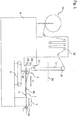
- Fig. 1 shows a sketched side view of a device according to the application for the intermittent conveying and cutting of a web 1.
- the device has a housing 6 or machine frame on which a roller 20 is rotatably arranged, which serves to carry the web 1 in the rolled up state.
- a drive controlled by a control (not illustrated further) is used, with which the roll 20 can be actively rotated for this purpose.
- the device also has a tensioning device 21 which is fastened to the housing 6 and which is designed and set up to receive the material web 1 unwound from the roll 20 and to provide it with a specific, desired tension. This counteracts an undesirable formation of waves in the web 1.
- the tensioning device 21 also has the function of a buffer, the tension being able to be adjusted by increasing or decreasing the section of the material web 1 accommodated in the tensioning device 21.
- the tensioning device 21 can, for example, have a vertically movable guide roller for the material web 1.
- the device also has an alignment unit 13 attached to the housing 6, which is designed and set up to receive the web 1 delivered by the tensioning device 21 and to align it laterally according to a target alignment with respect to a conveying direction R that is horizontal here.
- the alignment unit 13 is mounted rotatably about an axis of rotation 14 relative to the housing 6, the axis of rotation 14 being oriented at least essentially parallel to the conveying direction R.
- the alignment unit 13 has two rollers 22, 23 arranged at different heights for guiding the web 1, which are arranged transversely to the conveying direction R, the axis of rotation 14, about which the alignment unit 13 is rotatably mounted, in a central area, in particular in the Middle between the two rollers 22, 23 runs.
- the rollers 22, 23 are arranged fixed in their mutual position.
- the two rollers 22, 23 of the alignment unit 13 are non-driven rollers.
- the device To rotate the alignment unit 13 about the axis of rotation 14, the device has a drive motor for the alignment unit 13.
- a sensor is provided, which is arranged, for example, on a lower end region of the alignment unit 13.
- the device has two further rollers 24, 25, via which the web of material 1 is fed to a conveying device 3.
- the two further rollers 24, 25 are preferably each mounted so as to be rotatable about a horizontal axis of rotation relative to the housing 6.
- the conveying device 3 serves for the intermittent conveying of the web 1 in the conveying direction R.
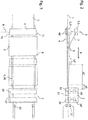
- the conveying device 3, shown in FIG Fig. 2 and a top view corresponding to this in Fig. 3 is shown in more detail, has a support 4 designed as a PTFE (Teflon®) film, by means of which a horizontal support surface 41 for the material web 1 is formed.
- the support 4 is arranged in a stationary manner on the housing 6 and is dimensioned such that the material web 1 can rest on the support surface 41 with its entire width.
- the conveying device 3 has a pressure and movement device 5 by means of which the material web 1 is intermittently conveyed in the conveying direction R, the material web 1 moving relative to the support 4.
- the conveyor device 3 is described in more detail below.
- the conveying direction R here denotes a direction in which the web 1 is conveyed by the pressure and movement device 5.
- the conveying direction R extends horizontally here.
- the device has a cutting device 2 fastened to the housing 6, with which the web 1 can be cut transversely to the conveying direction R, so that a cut sheet is formed.
- the alignment unit 13 makes it possible to achieve that the material web 1 is arranged for cutting with the intended lateral alignment.
- the device also has a gripping device with a gripping element 12, with which the web 1 can be pulled in the conveying direction R.
- the gripping device can on the Housing 6 of the device be mounted.
- the axis of rotation 14, about which the alignment unit 13 is rotatably mounted, extends in a plane which is oriented normal to the support surface 41 and which contains the conveying direction R.
- the pressure and movement device 5 is designed to produce and release a pressure with which the material web 1 is pushed against the support 4 and to generate a movement of the material web 1 relative to the support 4 in the conveying direction R.
- the conveyor device 3 is designed and set up to move the printing and moving device 5 for producing the print starting from a starting position S in the direction of the support 4 and then - while at least partially maintaining the pressure - by moving the printing and moving device 5 in the conveying direction R up to a front end position E to effect the movement of the web 1 relative to the support 4 in the conveying direction R.
- the pressure and movement device 5 is designed here as a bar-shaped pressure element extending transversely to the conveying direction R, which has an at least in a first approximation rectangular, downward-facing pressure or pressure contact surface for pressing contact with the web 1.
- the printing surface extends transversely to the conveying direction R over the entire width of the support 4.
- the conveying device 3 is designed in such a way that when the web 1 moves relative to the support 4 in the conveying direction, the web 1 adheres to the printing and moving device 5.
- the conveying device 3 has a linear guide 30 on each side of the support 4 with reference to the conveying direction R.
- the linear guides 30 are designed to guide the movement of the printing and movement device 5 starting from the starting position S in the direction of the support 4 into a rear printing position D.
- the linear guides 30 are designed for a vertically guided movement of the pressure and movement device 5.
- pneumatic cylinders controlled by the control can be provided, for example.
- the conveying device 3 also has a roller element 40, which acts as a counter-pressure element for the pressure and movement device 5 works.
- the roller element 40 is arranged here below the support 4;
- the roller element 40 has at least one roller which extends at right angles to the conveying direction R over the entire width of the support 4.
- the roller element 40 interacts with the linear guides 30, so that the roller element 30 is held immovable with respect to the linear guides 30 in the conveying direction R. In this way, a particularly suitable clamping of the web 1 for its conveyance in the conveying direction R can be brought about.
- the conveyor device 3 comprises a toothed belt arrangement 31 which is designed to move the movement of the printing and moving device 5 in the conveying direction R from the rearward printing position D into the front end position E.
- the linear guides 30 are attached to a toothed belt of the toothed belt arrangement 31.
- the variant is such that the linear guides 30 are moved by the toothed belt arrangement 31 in the conveying direction R and carry the printing and moving device 5 with them, whereby the mentioned movement of the printing and moving device 5 from the rear printing position D into the front end position E. is effected.
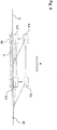
- the linear guides 30 are used to move the printing and moving device 5 - as in FIG Fig. 4 indicated - moves vertically upwards from the front end position E into a front release position L, which is at the same height as the starting position S and then moved by the toothed belt arrangement 31 counter to the conveying direction R into the starting position S.
- the conveying device 3 also has a hold-down device 7, which is movably mounted on the pressure and movement device 5 about a pivot axis 8 oriented transversely to the conveying direction R, so that when the web 1 moves relative to the support 4 in the conveying direction R, the holding-down device 7 with an end area 9 which is opposite the pivot axis 8 and which is located on one side of the pressure and movement device 5 which points in the conveying direction R and presses the web 1 against the support 4.
- the end area 9 is designed here as a straight edge area of the hold-down device 7 running transversely to the conveying direction R.
- the hold-down device 7 is mounted on the pressure and movement device 5 so that it can rotate or pivot freely, so that only the force of gravity acts on the hold-down device 7.
- the hold-down device 7 here has two arms 71, the pivot axis 8 running through the arms 71 and the arms 71 encompassing the pressure and movement device 5 on two opposite sides.
- the hold-down device 7 can, for example, be designed simply as a sheet metal plate in terms of production technology.
- the cutting device 2 has a cutting element 27 in the form of a rotatably mounted knife which can be moved transversely to the conveying direction by a drive so that the web 1 is cut through at an angle of 90 ° to the conveying direction R.
- the cutting device 2 has a clamping element 10 for producing and releasing a clamping of the material web 1 against a clamping support 11, which prevents movement of the material web 1 in and against the conveying direction R, the cutting device 2 being designed and set up for this purpose To move the clamping element 10 back and forth between a clamping position in which the clamping is effected and a release position in which the clamping is released.
- the cutting device 2 has a further clamping element 10 'designed analogously to the clamping element 10, as well as a corresponding further clamping support 11', the cutting element 27 being arranged between the clamping element 10 and the further clamping element 10 'as seen in the conveying direction R.
- the two clamping supports 11, 11 'form support areas for the web 1 which are at the same height as the support surface 41 formed by the support 4.
- the two mentioned clamping elements 10, 10 serve to hold the web 1 precisely in position during the cutting process.
- the end region 9 of the hold-down device 7 is very close to the cutting device 2 or to the clamping element 10, as seen in the conveying direction R Ensure arrangement of the web 1 in a particularly suitable manner.
- a distance a1 measured in the conveying direction R between the end region 9 of the hold-down device 7 and the clamping element 10 of the cutting device 2 is less than 20% of a distance a2 between the pressure and movement device 5 and the clamping element 10 of the cutting device 2.
- the device has a control device.
- the following sequence is particularly controlled by the controller and provided or can be set: In a first time interval, the clamping element 10 of the cutting device 2 is in the release position and the conveying device 3 effects the movement of the web 1 relative to the support 4 in the conveying direction R through the movement of the pressure and movement device 5.
- the pressure and movement device 5 is in the front end position E and the cutting device 2 moves the clamping element 10 from the release position into the clamping position.
- the clamping element 10 of the cutting device 2 is in the clamping position and the conveying device 3 moves the printing and moving device 5 from the front end position E into the starting position S.
- the end area 9 of the hold-down device 7 is designed in such a way that it can slide easily onto the web 1. This is advantageous during the movement of the printing and moving device 5 from the front end position E to the starting position S, because this contributes to the fact that the material web 1 is not moved counter to the conveying direction R as a result.
- a distance can be set by appropriately controlling the toothed belt arrangement 31 with the control device, which the printing and moving device 5 covers between the rearward printing position D and the front end position E.
- length adjustment can be provided via software.
- a web of material can be conveyed in the region of the cutting device or between the conveying device and the cutting device without undulating deformation.
- the device works with the aid of a comparatively simple sequence movement and it can be constructed from comparatively inexpensive components.
- the hold-down device is only moved passively.
- the gripping device grips the edge region of the material web 1 before the cutting of the material web 1 begins.
- the device is particularly suitable for a precise adjustment of the length of a sheet to be deposited.
- the device is particularly suitable for webs of material with a small material thickness, for example in the range of 100 ⁇ m.
- a comparatively high conveying speed can be achieved with the device.
Landscapes
- Life Sciences & Earth Sciences (AREA)
- Forests & Forestry (AREA)
- Engineering & Computer Science (AREA)
- Mechanical Engineering (AREA)
- Advancing Webs (AREA)
Applications Claiming Priority (1)
| Application Number | Priority Date | Filing Date | Title |
|---|---|---|---|
| DE102019006046.6A DE102019006046A1 (de) | 2019-08-27 | 2019-08-27 | Vorrichtung und Verfahren zum intermittierenden Fördern einer Warenbahn längs einer Förderrichtung und zum Schneiden der Warenbahn |
Publications (1)
| Publication Number | Publication Date |
|---|---|
| EP3789330A1 true EP3789330A1 (fr) | 2021-03-10 |
Family
ID=71994286
Family Applications (1)
| Application Number | Title | Priority Date | Filing Date |
|---|---|---|---|
| EP20188017.6A Pending EP3789330A1 (fr) | 2019-08-27 | 2020-07-28 | Dispositif et procédé de transport intermittent d'une bande de matériau le long d'une direction de transport et de coupe de la bande de matériau |
Country Status (2)
| Country | Link |
|---|---|
| EP (1) | EP3789330A1 (fr) |
| DE (1) | DE102019006046A1 (fr) |
Cited By (2)
| Publication number | Priority date | Publication date | Assignee | Title |
|---|---|---|---|---|
| CN113878629A (zh) * | 2021-09-24 | 2022-01-04 | 温州市众邦拉链有限公司 | 一种拉链带裁切设备 |
| CN114541125A (zh) * | 2022-03-10 | 2022-05-27 | 五洋纺机有限公司 | 一种纤维布条夹紧接料机构 |
Families Citing this family (1)
| Publication number | Priority date | Publication date | Assignee | Title |
|---|---|---|---|---|
| CN113815302B (zh) * | 2021-09-23 | 2023-07-18 | 深圳市博研商用设备有限公司 | 一种多织带丝网印刷机 |
Citations (4)
| Publication number | Priority date | Publication date | Assignee | Title |
|---|---|---|---|---|
| EP0000411A1 (fr) * | 1977-07-08 | 1979-01-24 | Franz Zettler | Procédé et dispositif pour le découpage de feuilles en feuillets individuels, suivi d'un empilage ordonné de ces derniers |
| DE3131101C2 (de) | 1980-09-04 | 1986-03-06 | Vits-Maschinenbau Gmbh, 4018 Langenfeld | Verfahren zum Querschneiden einer Warenbahn, insbes. aus Papier, Kunststoff oder Metall und Stapeln der geschnittenen Bogen sowie Vorrichtung zur Durchführung des Verfahrens |
| EP0822915A1 (fr) * | 1995-04-21 | 1998-02-11 | Böwe Systec Ag | Procede et dispositif de refente d'une bande de papier en sens travers |
| US20040076799A1 (en) * | 2001-02-14 | 2004-04-22 | Wolfgang Schafer | Method and device for producing thin wafers from a film of active ingredients |
Family Cites Families (2)
| Publication number | Priority date | Publication date | Assignee | Title |
|---|---|---|---|---|
| JPS55154192A (en) * | 1979-05-22 | 1980-12-01 | Oki Electric Ind Co Ltd | Paper feeding device in printer |
| US4483472A (en) * | 1983-03-01 | 1984-11-20 | Gerber Scientific Inc. | Apparatus and method for indexing sheet material |
-
2019
- 2019-08-27 DE DE102019006046.6A patent/DE102019006046A1/de active Pending
-
2020
- 2020-07-28 EP EP20188017.6A patent/EP3789330A1/fr active Pending
Patent Citations (4)
| Publication number | Priority date | Publication date | Assignee | Title |
|---|---|---|---|---|
| EP0000411A1 (fr) * | 1977-07-08 | 1979-01-24 | Franz Zettler | Procédé et dispositif pour le découpage de feuilles en feuillets individuels, suivi d'un empilage ordonné de ces derniers |
| DE3131101C2 (de) | 1980-09-04 | 1986-03-06 | Vits-Maschinenbau Gmbh, 4018 Langenfeld | Verfahren zum Querschneiden einer Warenbahn, insbes. aus Papier, Kunststoff oder Metall und Stapeln der geschnittenen Bogen sowie Vorrichtung zur Durchführung des Verfahrens |
| EP0822915A1 (fr) * | 1995-04-21 | 1998-02-11 | Böwe Systec Ag | Procede et dispositif de refente d'une bande de papier en sens travers |
| US20040076799A1 (en) * | 2001-02-14 | 2004-04-22 | Wolfgang Schafer | Method and device for producing thin wafers from a film of active ingredients |
Cited By (2)
| Publication number | Priority date | Publication date | Assignee | Title |
|---|---|---|---|---|
| CN113878629A (zh) * | 2021-09-24 | 2022-01-04 | 温州市众邦拉链有限公司 | 一种拉链带裁切设备 |
| CN114541125A (zh) * | 2022-03-10 | 2022-05-27 | 五洋纺机有限公司 | 一种纤维布条夹紧接料机构 |
Also Published As
| Publication number | Publication date |
|---|---|
| DE102019006046A1 (de) | 2021-03-04 |
Similar Documents
| Publication | Publication Date | Title |
|---|---|---|
| DE102006014454B3 (de) | Stanzvorrichtung mit Zuführeinrichtung | |
| EP3789330A1 (fr) | Dispositif et procédé de transport intermittent d'une bande de matériau le long d'une direction de transport et de coupe de la bande de matériau | |
| DE69116411T2 (de) | Applikator und Methode um einen Materialstreifen zu drehen und auf ein Band zu plazieren | |
| DE69821414T2 (de) | Schneid- und Rillmaschine mit einer Vorrichtung zum Längsschneiden | |
| EP2415700A2 (fr) | Dispositif d'orientation d'un produit plat | |
| DE2420481B2 (de) | Furnierschneidvorrichtung | |
| DE1135690B (de) | Kartenvorschub fuer Anordnungen zum schnellen zaehlpunktstellenweisen Lochen von Karten | |
| EP3254767A2 (fr) | Dispositif de pose de fond de sac pour la fabrication de sacs | |
| EP2246160A1 (fr) | Dispositif et procédé de coupe de matériau en tissu ou en non-tissé en forme de bande ou d'arc et laissant passer l'air | |
| EP1012097B1 (fr) | Dispositif de guidage d'une bande de papier sans fin | |
| DE3904385A1 (de) | Vorrichtung zum seitlichen ausrichten einer stoffkante beim naehen | |
| DE2428113C2 (de) | Vorrichtung zum einseitig kantengeraden Aufwickeln von Warenbahnen | |
| DE4419963C1 (de) | Kreuzbandschleifmaschine zum beiderseitigen Anfasen des Randes von Glasplatten | |
| DD282438A5 (de) | Vorrichtung zum zufuehren von bogen an eine bogenverarbeitende maschine, insbesondere druckmaschine | |
| DE10012000A1 (de) | Rollenwechsler für eine Vorrichtung zum Herstellen von Hygieneprodukten | |
| DE820867C (de) | Vorrichtung zum Aufschneiden von Briefumschlaegen | |
| DE102010051844B4 (de) | Verfahren und Vorrichtung zum Einbringen eines Dichtungsprofils | |
| DE19836211A1 (de) | Rotationsschneideverfahren für Folienbahnen und dergleichen sowie Vorrichtung zur Durchführung des Verfahrens | |
| DE3503715C2 (fr) | ||
| DE102018130149B4 (de) | Anlage für eine tafelförmiges Substrat verarbeitende Maschine und Verfahren zum Betreiben einer Anlage | |
| DE3539591C2 (fr) | ||
| EP0017204A1 (fr) | Dispositif pour le pliage de feuilles de papier ou analogues | |
| DE2729603C2 (fr) | ||
| DE2325319C2 (de) | Vorrichtung zur gesteuerten Ablagerung eines Materials auf einem laufenden, endlosen Band | |
| DE29601452U1 (de) | Stapelvorrichtung für kartenförmige Güter |
Legal Events
| Date | Code | Title | Description |
|---|---|---|---|
| PUAI | Public reference made under article 153(3) epc to a published international application that has entered the european phase |
Free format text: ORIGINAL CODE: 0009012 |
|
| STAA | Information on the status of an ep patent application or granted ep patent |
Free format text: STATUS: REQUEST FOR EXAMINATION WAS MADE |
|
| 17P | Request for examination filed |
Effective date: 20200728 |
|
| AK | Designated contracting states |
Kind code of ref document: A1 Designated state(s): AL AT BE BG CH CY CZ DE DK EE ES FI FR GB GR HR HU IE IS IT LI LT LU LV MC MK MT NL NO PL PT RO RS SE SI SK SM TR |
|
| AX | Request for extension of the european patent |
Extension state: BA ME |
|
| STAA | Information on the status of an ep patent application or granted ep patent |
Free format text: STATUS: EXAMINATION IS IN PROGRESS |
|
| 17Q | First examination report despatched |
Effective date: 20230602 |