EP3786580B1 - Surveying instrument including guide light irradiation unit - Google Patents
Surveying instrument including guide light irradiation unit Download PDFInfo
- Publication number
- EP3786580B1 EP3786580B1 EP20192416.4A EP20192416A EP3786580B1 EP 3786580 B1 EP3786580 B1 EP 3786580B1 EP 20192416 A EP20192416 A EP 20192416A EP 3786580 B1 EP3786580 B1 EP 3786580B1
- Authority
- EP
- European Patent Office
- Prior art keywords
- guide light
- surveying instrument
- irradiation unit
- light irradiation
- lens barrel
- Prior art date
- Legal status (The legal status is an assumption and is not a legal conclusion. Google has not performed a legal analysis and makes no representation as to the accuracy of the status listed.)
- Active
Links
Images


Classifications
-
- G—PHYSICS
- G01—MEASURING; TESTING
- G01C—MEASURING DISTANCES, LEVELS OR BEARINGS; SURVEYING; NAVIGATION; GYROSCOPIC INSTRUMENTS; PHOTOGRAMMETRY OR VIDEOGRAMMETRY
- G01C15/00—Surveying instruments or accessories not provided for in groups G01C1/00 - G01C13/00
- G01C15/02—Means for marking measuring points
-
- G—PHYSICS
- G01—MEASURING; TESTING
- G01C—MEASURING DISTANCES, LEVELS OR BEARINGS; SURVEYING; NAVIGATION; GYROSCOPIC INSTRUMENTS; PHOTOGRAMMETRY OR VIDEOGRAMMETRY
- G01C15/00—Surveying instruments or accessories not provided for in groups G01C1/00 - G01C13/00
- G01C15/002—Active optical surveying means
-
- G—PHYSICS
- G01—MEASURING; TESTING
- G01C—MEASURING DISTANCES, LEVELS OR BEARINGS; SURVEYING; NAVIGATION; GYROSCOPIC INSTRUMENTS; PHOTOGRAMMETRY OR VIDEOGRAMMETRY
- G01C3/00—Measuring distances in line of sight; Optical rangefinders
- G01C3/02—Details
Definitions
- the present invention relates to a surveying instrument including a guide light irradiation unit that irradiates guide light to guide a survey operator.
- Patent Literature 1 discloses a surveying instrument including a surveying instrument main body that supports a lens barrel portion of a distance-measuring optical system vertically rotatably, a guide light irradiation unit that irradiates guide light, and a cover member that covers the surveying instrument main body including the lens barrel portion and the guide light irradiation unit.
- the guide light irradiation unit is installed on an upper portion of the surveying instrument main body and covered by the cover member, so that an optical axis of the guide light irradiation unit does not need to be adjusted even when the cover member is removed.
- the guide light consists of light differing in pattern between the left and the right of a vertical plane including the optical axis, and is irradiated while extending in the up-down direction.
- Patent Literature 1 the guide light in Patent Literature 1 is diffused in the up-down direction by using a cylindrical lens, and this poses a problem in which a guide light reach distance becomes shorter according to the diffusion of the guide light.
- a guide light irradiation unit is configured by juxtaposing a plurality of guide light irradiators so that the irradiators have angles in the up-down direction. Accordingly, it becomes possible to extend the light reach distance and to irradiate a guide light extending in the up-down direction.
- US 2015/052765 A1 and US 2012/242830 A1 disclose surveying instruments having a vertically-rotating ranging light and a guide light with different colours on the left and on the right of the ranging axis, so as to indicate to the operator in which direction they should move.
- a rotation range of the lens barrel portion is wide, and the use range of the surveying instrument can be expanded by extending in the up-down direction a window that is provided in the cover member and transmits distance-measuring laser light, however, the cover member itself is also inevitably extended in the up-down direction, and further, when a plurality of guide light irradiators are juxtaposed in the up-down direction above the window so that a collimation axis and the optical axis of the guide light match in the vertical direction, this poses a problem in which the size in the up-down direction is significantly increased.
- the present invention was made in view of this problem, and provides a surveying instrument entirely covered by a cover member and configured so that the size of the cover member (housing) is held within an appropriate range, while a guide light irradiation range and a survey range are extended.
- the guide light irradiation unit even when the guide light irradiation unit is disposed to be shifted in the horizontal direction from a state where the optical axis of the guide light irradiation unit matches the optical axis of the lens barrel portion in the horizontal direction, guide light can be visually recognized even at the shortest use distance, so that the effect of the shifting disposition in the horizontal direction can be negated.
- the guide light irradiation unit no longer needs to be disposed above the lens barrel portion, so that the use range of the lens barrel portion in the up-down direction can be accordingly expanded, and in line therewith, the guide light use range can also be expanded.
- the housing When the use range is expanded while the guide light irradiation unit is kept above the lens barrel portion, the housing needs to be greatly extended in the up-down direction, but, by an horizontal shifting disposition, the housing does not need to be greatly enlarged as compared to the expansion of the use range, so that the size of the housing can be held within an appropriate range.
- a surveying instrument including a guide light irradiation unit and a housing whose size is held within an appropriate range can be provided.
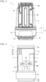
- FIG. 1 is a schematic perspective view for illustrating an outline of a surveying instrument 1 according to the present invention.
- the surveying instrument 1 is a total station having a distance and angle measuring function and a tracking function, and is capable of irradiating guide light G for guiding an operator.
- the guide light G consists of light differing in pattern between the left and the right of an optical axis center, and is irradiated in a fan shape extending in the up-down direction.
- the optical axis of the guide light G is substantially parallel to a collimation direction of the surveying instrument 1 on a horizontal plane, and is configured to be at a predetermined distance in the horizontal direction from a collimation axis, however, in an operation process for guiding an operator by the guide light G, the distance is sufficiently negligible (described later). Therefore, it is regarded that fan-shaped guide light G differing in pattern between the left and the right of the collimation axis of the surveying instrument 1 as a boundary on a horizontal plane and extending horizontally is irradiated.
- the surveying instrument 1 is mounted on a tripod 2 and installed at a known point, and is collimated in a direction toward a piling point P1, and irradiates guide light G.
- An operator holding a pole 40 equipped with a prism 60 as a target of the surveying instrument 1 can determine by himself/herself which side the operator should move to, the left or the right, according to a pattern of the guide light G viewed from the surveying instrument 1.
- the guide light G is configured so that, as viewed from an operator side, red light is viewed at the right side, and green light is viewed at the left side, and therefore, when the operator confirms red light, the operator is on the right side relative to the piling point P, so that it is only necessary to move leftward from a current location while facing the surveying instrument 1.
- the operator is guided to the front of an irradiation unit for the guide light G (the collimation direction of the surveying instrument 1) that is a direction in which left and right colors of the guide light G are substantially equally viewable.
- the guide light G goes off. Based on this, the operator can know that the target has been locked on.
- a distance and an angle to the prism 60 are measured by the surveying instrument 1, difference information between a current location of the prism 60 and the piling point P1 is transmitted to a terminal such as a tablet that the operator carries with him/her, and the operator is guided in more detail, and the pole 40 is erected at the piling point P1. Accordingly, the piling point P1 can be highly accurately set.
- the guide light G is configured to extend vertically, and therefore, even when there is a level difference between the piling points P2 and P3, an operator can easily find the guide light G.
- the surveying instrument 1 also has a wide survey range in the vertical direction, and is suitable for a survey site with great level differences.
- lights in various patterns can be used such as, in addition to light in colors different between the left and the right, one of which being a blinking light and the other being a continuous light, or light different in blinking periods between the left and the right.
- FIG. 2 is a front view of the surveying instrument 1
- FIG. 3 is a schematic view schematically illustrating an internal structure of the surveying instrument 1.
- the surveying instrument 1 is configured to include a surveying instrument main body 5 made up of a base portion 3 and a rotating pedestal 4 to be rotated horizontally with respect to the base portion 3, and a cover member 6.
- the base portion 3 mainly consists of a fixing seat 3a to be fixed to a tripod 2, a leveling base 3b including a leveling screw (not illustrated), and a case 3c which incorporates a drive mechanism such as a horizontal driving motor M1 that drives the rotating pedestal 4 to rotate horizontally.
- a pair of support members 7 and 7 are erected. Between the pair of support members 7 and 7, a lens barrel portion 8 of a distance-measuring optical system and a tracking optical system is disposed.
- the lens barrel portion 8 is vertically rotatably supported by a horizontal shaft 8A provided across the pair of support members 7 and 7.
- a vertical driving motor M2 that drives the lens barrel portion 8 to rotate vertically is fixed, and at the other end portion, an encoder 10 for detecting a rotation angle of the lens barrel portion 8 is provided.
- a control circuit board 11 that controls the horizontal rotation of the rotating pedestal 4 and the vertical rotation of the lens barrel portion 8 is disposed, and at an upper end portion of the other support member 7, a guide light irradiation unit 50 is disposed.
- the horizontal driving motor M1, the vertical driving motor M2, and the encoder 10, etc., are connected to the control circuit board 11, and in the control circuit board 11, a CPU 9 to be described later is provided.
- the guide light irradiation unit 50 irradiates guide light G to guide a survey operator.
- An optical axis L of the guide light G and an optical axis L2 of the lens barrel portion 8 are configured so as to become substantially parallel to each other in a plan view.
- the cover member 6 has a handle portion 6a on an upper surface, a window 6b extending in the up-down direction on a front surface, and a guide light window 6c at an upper corner of the front surface.
- the window 6b is formed on the optical axis of the lens barrel portion 8, and transmits infrared laser light of the distance-measuring and tracking optical systems to be described later.
- the guide light window 6c is formed on the optical axis of the guide light G, and transmits the guide light G.
- the window 6b is perpendicular to the optical axis of the infrared laser light, the infrared laser light reflected by the window 6b directly returns and adversely affects distance and angle measurements, so that to avoid this, the window 6b is disposed so as not to become perpendicular to the optical axis of the infrared laser light and slightly tilted in the horizontal direction so as to prevent errors caused by the reflection.
- a seal member (not illustrated) to prevent entrance of rainwater, etc., is provided.
- cover member 6 There are clearances provided between the cover member 6 and the guide light irradiation unit 50; the cover member 6 and the control circuit board 11. Accordingly, when attaching and removing the cover member 6, the cover member 6 can be prevented from making contact with the guide light irradiation unit 50. Even when an impact from the outside is applied to the cover member 6, it is possible to prevent the control circuit board 11 and the guide light irradiation unit 50 inside the cover member 6 from being affected as much as possible.
- the cover member 6 covers the guide light irradiation unit 50 and the lens barrel portion 8 while separating from these, and even when the cover member 6 is removed, there is no need to adjust the optical axes of the guide light irradiation unit 50 and the lens barrel portion 8.
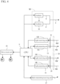
- FIG. 4 is a block circuit diagram illustrating a configuration of optical systems of the surveying instrument 1.
- the CPU 9 includes circuits for performing various arithmetic operations and a memory, and to the CPU 9, a radio transmitting/receiving unit 37, a distance-measuring optical system 13, a tracking optical system 14, a drive circuit unit 35, and the guide light irradiation unit 50 are connected, and the CPU 9 performs arithmetic operations from data and programs in the memory and input data and received data, and issues command signals and controls these connected components.
- the distance-measuring optical system 13 and the tracking optical system 14 are provided.
- the distance-measuring optical system is described first.
- the distance-measuring optical system 13 includes a light transmission unit 13A and a light receiving unit 13B.
- the light transmission unit 13A has a light source 13A'
- the light receiving unit 13B has a light receiving element 13B'.
- the light source 13A' emits infrared laser light.
- the infrared laser light is reflected to an objective lens 19 by a dichroic mirror surface 18a of a beam splitter 18, and emitted to the outside of the surveying instrument 1 through a cover glass 20 and emitted as parallel light PB3.
- the parallel light PB3 is reflected by the prism 60 (refer to FIG. 1 ) as a target of the surveying instrument 1, returns as reflected light PB3' to the objective lens 19 through the cover glass 20, and is reflected by a dichroic mirror surface 18b of the beam splitter 18 and converged into the light receiving element 13B'.
- a light receiving output of the light receiving element 13B' is input to the CPU 9.
- the CPU 9 operates a distance to the prism 60 based on the light receiving output of the light receiving element 13B'.
- this tracking optical system 14 is used to lock on the prism 60. As illustrated in FIG. 6 , this tracking optical system 14 includes a laser diode 23, a collimating lens 24, reflection mirrors 25 and 26, an objective lens 30, the cover glass 20, a noise light removing filter 33, and a light receiving element 34.
- the laser diode 23, the collimating lens 24, and the reflection mirrors 25 and 26 constitute most of a light transmission unit 14A.
- the objective lens 30, the noise light removing filter 33, and the light receiving element 34 constitute most of a light receiving unit 14B.
- the laser diode 23 emits, as tracking light, infrared laser light PB4 of a wavelength different from a wavelength of distance-measuring light of the distance-measuring optical system 13.
- the infrared laser light PB4 is collimated to be substantially parallel light by the collimating lens 24.
- the infrared laser light PB4 reflected by the reflection mirrors 25 and 26 is emitted to the outside of the surveying instrument 1 through the cover glass 20, and by this infrared laser light PB4, the prism 60 is searched for and scanned.
- the prism 60 is in the search range, the infrared laser light PB4 is reflected by the prism 60 and returns to the objective lens 30.
- the reflected light PB4' of the infrared laser light PB4 is converged by the objective lens 30, and passes through the noise light removing filter 33 to be imaged on the light receiving element 34.
- the noise light removing filter 33 has a function to transmit light of the same wavelength as that of the reflected light PB4'.
- the objective lens 30 of the tracking optical system 14 and the objective lens 19 of the distance-measuring optical system 13 are configured as separate members, however, these lenses may be integrally configured.
- the surveying instrument 1 includes the drive circuit unit 35 (refer to FIG. 4 ). To this drive circuit unit 35, the horizontal driving motor M1 and the vertical driving motor M2 are connected.
- the drive circuit unit 35 is controlled by the CPU 9, and the CPU 9 has a function to output a rotation permission signal for the horizontal driving motor M1 to the drive circuit unit 35 when the radio transmitting/receiving unit 37 receives a lens barrel portion rotation permission signal.
- the CPU 9 operates a rotation angle in the horizontal direction from a current angle in the horizontal direction that the lens barrel portion 8 of the surveying instrument 1 faces to a next piling point based on a reference azimuth signal and the lens barrel portion rotation permission signal.
- the drive circuit unit 35 can drive the horizontal driving motor M1 to rotate the lens barrel portion 8 from the direction in which the piling point P1 is present to the direction in which the next piling point P2 is present and stop the lens barrel portion at a position after the rotation.
- the drive circuit unit 35 has a function to rotate the vertical driving motor M2 forward and reversely, and accordingly, by rotating the lens barrel portion 8 in the up-down direction, the infrared laser light PB4 of the tracking optical system 14 can be reciprocated for scanning in the up-down direction.
- the guide light irradiation unit 50 includes a plurality of (in the present embodiment, two) irradiators 55 (refer to FIG. 4 ).
- the irradiator 55 irradiates basic guide light G' that differs in pattern between the left and the right of a vertical plane including an optical axis L' as an irradiation direction. Synthetic light of the basic guide lights G' irradiated from the plurality of irradiators 55 is visually recognized as guide light G.
- the irradiator 55 is described with reference to FIGS. 7A and 7B .
- the irradiated light is colored.
- FIG. 7B a light-emitting diode 57a, 57b is omitted and only the light source 57aS, 57bS is illustrated, and because dispositions of the light sources 57aS and 57bS match each other in a side view, one light source disposed at the rear side is noted in parentheses.
- the irradiator 55 includes, as optical systems, a pair of light-emitting diodes 57a and 57b, a right-angle mirror 56, and a lens 58 that is a collimating lens as a condenser lens.
- the right-angle mirror 56 has reflecting surfaces 56a and 56b, and the angle formed by these is a right angle.
- the right-angle mirror 56 is disposed so that a ridge of the reflecting surfaces 56a and 56b matches a vertical plane passing through a rear focal point of the lens 58 on an optical axis L' of the lens 58.
- the reflecting surfaces 56a and 56b face the lens 58 side, and tilt at equal angles in directions opposite to the optical axis L'.
- the red light-emitting diode 57a is disposed on a reflecting optical axis La of one reflecting surface 56a
- the green light-emitting diode 57b is disposed on a reflecting optical axis Lb of the other reflecting surface 56b.
- Diaphragm portions 59a and 59b are provided directly in front of the red light-emitting diode 57a and the green light-emitting diode 57b.
- the diaphragm portions 59a and 59b serve to cut each of the respective lights in half.
- Red light irradiated from the light source 57aS of the red light-emitting diode 57a is reflected by the reflecting surface 56a, and similarly, green light emitted from the light source 57bS of the green light-emitting diode 57b is reflected by the reflecting surface 56b, and are irradiated as basic guide light G' from the lens 58 while being divided into two emission colors by the vertical plane including the optical axis L'.
- the basic guide light G' that has exited from the lens 58 is irradiated forward in an irradiation direction set along the optical axis L' while being diffused at a diffusion angle ⁇ as an expansion angle in both of the vertical direction and the horizontal direction (diffused by ⁇ /2 to each side of the optical axis L' as a center).
- An apex of the right-angle mirror 56 is disposed at an image forming position (rear focal point) when looking into the lens 58 from a distance, so that a boundary between the red light and the green light can be projected sharply and clearly.
- the guide light irradiation unit 50 in which the two irradiators 55 are disposed is described with reference to FIG. 8 .
- the two irradiators 55 and 55 are arranged one above the other while tilting the end portion sides with the lenses 58 close to each other so that optical axes L' and L' of the two irradiators 55 and 55 substantially match in a plan view, and form a predetermined angle ⁇ with each other in the vertical direction.
- the dispositions are adjusted so that the angle ⁇ in the vertical direction between the two irradiators 55 and 55 becomes smaller than the light diffusion angle ⁇ of a single irradiator 55 in the vertical direction.
- an angle resolution (visual angle) of a human eye having 20/20 vision is 1 arc-minute
- the light sources are viewed as not individual light sources but one light source as a sum of brightnesses of the respective light sources viewed singly. That is, by setting the angle ⁇ to 1 arc-minute or less, lights irradiated from the irradiators 55 and 55 are viewed as being summed for an operator, and an effect of extending a reach distance of the synthesized guide light G to be longer than the basic guide light G' of a single irradiator 55 is obtained.
- two irradiators 55 and 55 are arranged one above the other, the two irradiators 55 and 55 irradiate light in a state where the optical axes L' are tilted at equal angles upward and downward from the horizontal, so that the guide light G is extended to be longer in the up-down direction than the basic guide light G', and this enables use at a location with level differences, and enables the guide light G to be easily found.
- An apparent optical axis L as an irradiation direction of the guide light G irradiated from the guide light irradiation unit 50 is a sum of the optical axes L' (as vectors) of the two irradiators 55.
- the two irradiators 55 and 55 are disposed one above the other at equal angles, so that the optical axis L becomes horizontal, and the guide light G is irradiated while being diffused evenly in the up-down direction.
- the disposition of the guide light irradiation unit 50 is described. As illustrated in FIG. 9 , the optical axis L of the guide light irradiation unit 50 and the optical axis L2 of the lens barrel portion 8 are parallel to each other in a plan view, and respective vertical planes including the optical axes are at a distance D from each other. That is, the guide light irradiation unit 50 is disposed to be shifted by the distance D horizontally from the lens barrel portion 8.
- the guide light G can be visually recognized at and ahead of the intersection Pmin, (refer to the arrow in FIG. 9 ).
- a diffusion angle of the guide light G in the horizontal direction is equal to the diffusion angle ⁇ of the basic guide lights G', so that when Cx is a distance from the surveying instrument 1 (central point as a reference) to the intersection Pmin, the following relationship holds.
- tan ⁇ / 2 ⁇ Cx D
- the guide light G is visually recognized from the shortest use distance of the surveying instrument 1.
- the relational expression is as follows.
- tan ⁇ /2 ⁇ Cmin Dmax
- the guide light G can be visually recognized from the shortest use distance of the surveying instrument 1.
- a visual recognition range of the guide light G becomes equal to that in a case where the optical axis of the guide light irradiation unit 50 is disposed so as to substantially match the collimation axis on a horizontal plane, and the effect from shifting of the optical axes from each other in the horizontal direction is negated. Therefore, the distance D is set so as to satisfy: tan ⁇ /2 ⁇ Cmin > D
- the surveying instrument 1 is used near the shortest use distance Cmin, even if guidance by the guide light G is not given, the front surface of the surveying instrument 1 can be visually recognized because the distance is short, so that there is no problem in actual use.
- this level of offset distance is sufficiently negligible.
- an operator is guided to the vicinity of the piling point P by the guide light G, and then, a distance and an angle to the prism 60 are measured, and accordingly, the piling point P is highly accurately settled.
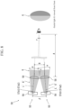
- a surveying instrument 1A is illustrated as a modification in FIG. 10 .
- a window 6b' of the surveying instrument 1A extends in the up-down direction on the front surface of the cover member 6, and is further continuously extended from an upper end of the front surface to the middle of the upper surface, to be formed over the two surfaces of the front surface and the upper surface.
- Support members 7 and 7 are a pair of columns, and a lens barrel portion 8 positioned between the support members 7 and 7 is rotatably supported by a horizontal shaft 8A provided across the support members 7 and 7, and can face straight up as well.
- a guide light irradiation unit 50 is disposed not straight over the lens barrel portion 8 but disposed by separating at a distance D horizontally, so that only the cover member 6 is present above the lens barrel portion 8.
- a handle portion 6a is provided by tilting so as to avoid the center of the upper surface. Therefore, the window 6b' can be formed by extending to the upper surface of the cover member 6. Accordingly, the use range of the surveying instrument 1A can be further expanded, and the maximum angle can be increased to approximately +90°.
- the irradiation range of the guide light G in the vertical direction is also extended by, for example, using three or more irradiators 55 for the built-in guide light irradiation unit 50 and disposing the irradiators 55 at equal angles.
- FIG. 11 illustrates a surveying instrument 1B of another modification.
- the disposition of a guide light irradiation unit 50' substantially matches the disposition of a lens barrel portion 8 in the up-down direction.
- the angle relationship between the guide light irradiation unit 70' and the lens barrel portion 8 in the vertical direction becomes equal, so that it no longer becomes necessary to consider adjustments, etc.
- the guide light irradiation unit 50' may be held by one support member 7 so as to become rotatable around a horizontal axis 50A.
- the guide light irradiation unit 50' may be held by the support member 7 so as to become slidable on a vertical axis 50B.
- the irradiation range of the guide light G can be expanded in the vertical direction.
- the guide light window 6c is also formed in line with the configuration described above, and extended vertically, or further continuously extended to the upper surface in the same manner as the window 6b'.
Landscapes
- Physics & Mathematics (AREA)
- Engineering & Computer Science (AREA)
- General Physics & Mathematics (AREA)
- Radar, Positioning & Navigation (AREA)
- Remote Sensing (AREA)
- Electromagnetism (AREA)
- Optical Radar Systems And Details Thereof (AREA)
Applications Claiming Priority (1)
| Application Number | Priority Date | Filing Date | Title |
|---|---|---|---|
| JP2019155973A JP7299669B2 (ja) | 2019-08-28 | 2019-08-28 | ガイド光照射部を備えた測量機 |
Publications (2)
| Publication Number | Publication Date |
|---|---|
| EP3786580A1 EP3786580A1 (en) | 2021-03-03 |
| EP3786580B1 true EP3786580B1 (en) | 2025-01-08 |
Family
ID=72234726
Family Applications (1)
| Application Number | Title | Priority Date | Filing Date |
|---|---|---|---|
| EP20192416.4A Active EP3786580B1 (en) | 2019-08-28 | 2020-08-24 | Surveying instrument including guide light irradiation unit |
Country Status (4)
| Country | Link |
|---|---|
| US (1) | US11703329B2 (enExample) |
| EP (1) | EP3786580B1 (enExample) |
| JP (1) | JP7299669B2 (enExample) |
| CN (1) | CN112444236B (enExample) |
Families Citing this family (5)
| Publication number | Priority date | Publication date | Assignee | Title |
|---|---|---|---|---|
| JP7299669B2 (ja) * | 2019-08-28 | 2023-06-28 | 株式会社トプコン | ガイド光照射部を備えた測量機 |
| WO2022186304A1 (ja) | 2021-03-02 | 2022-09-09 | Agc株式会社 | ペンタフルオロスルファニル基含有アリール化合物の製造方法 |
| JP2024161696A (ja) * | 2023-05-08 | 2024-11-20 | 株式会社トプコン | 測量装置及び測量システム |
| WO2024262414A1 (ja) * | 2023-06-23 | 2024-12-26 | 株式会社トプコン | ガイド光照射装置 |
| JP2025006809A (ja) * | 2023-06-30 | 2025-01-17 | 株式会社トプコン | 測量装置 |
Family Cites Families (12)
| Publication number | Priority date | Publication date | Assignee | Title |
|---|---|---|---|---|
| JP2587810Y2 (ja) * | 1991-09-26 | 1998-12-24 | 株式会社ソキア | ガイド光装置 |
| JP4320099B2 (ja) | 1999-03-26 | 2009-08-26 | 株式会社トプコン | 測量装置 |
| JP5166087B2 (ja) * | 2008-03-21 | 2013-03-21 | 株式会社トプコン | 測量装置及び測量システム |
| JP5725922B2 (ja) * | 2011-03-25 | 2015-05-27 | 株式会社トプコン | 測量システム及びこの測量システムに用いる測量用ポール及びこの測量システムに用いる携帯型無線送受信装置 |
| JP6227324B2 (ja) * | 2013-08-23 | 2017-11-08 | 株式会社トプコン | 測量機及び測量作業システム |
| JP6209021B2 (ja) | 2013-08-23 | 2017-10-04 | 株式会社トプコン | 測量機 |
| JP6253973B2 (ja) * | 2013-12-27 | 2017-12-27 | 株式会社トプコン | 測量装置 |
| JP6553999B2 (ja) * | 2015-09-17 | 2019-07-31 | 株式会社トプコン | ポリゴンミラーとファンビーム出力装置と測量システム |
| EP3220163B1 (de) * | 2016-03-15 | 2021-07-07 | Leica Geosystems AG | Lasertracker mit zwei messfunktionalitäten |
| JP6713847B2 (ja) * | 2016-06-14 | 2020-06-24 | 株式会社トプコン | 測量システム |
| JP6965673B2 (ja) | 2017-10-03 | 2021-11-10 | 富士電機株式会社 | 硬貨処理装置 |
| JP7299669B2 (ja) * | 2019-08-28 | 2023-06-28 | 株式会社トプコン | ガイド光照射部を備えた測量機 |
-
2019
- 2019-08-28 JP JP2019155973A patent/JP7299669B2/ja active Active
-
2020
- 2020-07-30 CN CN202010748355.4A patent/CN112444236B/zh active Active
- 2020-08-05 US US16/985,778 patent/US11703329B2/en active Active
- 2020-08-24 EP EP20192416.4A patent/EP3786580B1/en active Active
Also Published As
| Publication number | Publication date |
|---|---|
| US11703329B2 (en) | 2023-07-18 |
| EP3786580A1 (en) | 2021-03-03 |
| US20210063153A1 (en) | 2021-03-04 |
| JP2021032818A (ja) | 2021-03-01 |
| JP7299669B2 (ja) | 2023-06-28 |
| CN112444236B (zh) | 2023-08-15 |
| CN112444236A (zh) | 2021-03-05 |
Similar Documents
| Publication | Publication Date | Title |
|---|---|---|
| EP3786580B1 (en) | Surveying instrument including guide light irradiation unit | |
| CN1330929C (zh) | 位置确定装置 | |
| CN101539423B (zh) | 勘测装置和勘测系统 | |
| EP2447666B1 (en) | Laser surveying instrument | |
| EP2381272B1 (en) | Laser scanner | |
| CN104422429B (zh) | 测量机 | |
| US20210124021A1 (en) | Laser scanner | |
| JPH1038571A (ja) | 回転レーザ装置 | |
| JP4323046B2 (ja) | 器械の高さ測定装置付き測量器械 | |
| CN111580127B (zh) | 具有旋转反射镜的测绘系统 | |
| JPH0829536A (ja) | 光軸検出装置及び光軸検出方法 | |
| CN111766562A (zh) | 一种隧道掘进导向方法及导向系统 | |
| EP3715784B1 (en) | Guide light irradiation device | |
| JP2007333565A (ja) | ヘッドライトテスタ | |
| EP3722748B1 (en) | Guide light irradiation device | |
| JPH1019561A (ja) | 測距装置 | |
| JPH11101642A (ja) | ビーム像の水平調整方法およびビーム像水平調整装置 | |
| US12560431B2 (en) | Surveying system and method of operating a surveying system | |
| JP4267971B2 (ja) | レーザ光線照準装置及び光軸補償方法 | |
| JP2627105B2 (ja) | 工事用測量機械 | |
| CN119856070A (zh) | 用于定位对象的装置和系统 | |
| JP2025015890A (ja) | 測量装置 | |
| JPH07218618A (ja) | レーザレーダ光軸調整装置 |
Legal Events
| Date | Code | Title | Description |
|---|---|---|---|
| PUAI | Public reference made under article 153(3) epc to a published international application that has entered the european phase |
Free format text: ORIGINAL CODE: 0009012 |
|
| STAA | Information on the status of an ep patent application or granted ep patent |
Free format text: STATUS: THE APPLICATION HAS BEEN PUBLISHED |
|
| AK | Designated contracting states |
Kind code of ref document: A1 Designated state(s): AL AT BE BG CH CY CZ DE DK EE ES FI FR GB GR HR HU IE IS IT LI LT LU LV MC MK MT NL NO PL PT RO RS SE SI SK SM TR |
|
| AX | Request for extension of the european patent |
Extension state: BA ME |
|
| STAA | Information on the status of an ep patent application or granted ep patent |
Free format text: STATUS: REQUEST FOR EXAMINATION WAS MADE |
|
| 17P | Request for examination filed |
Effective date: 20210818 |
|
| RBV | Designated contracting states (corrected) |
Designated state(s): AL AT BE BG CH CY CZ DE DK EE ES FI FR GB GR HR HU IE IS IT LI LT LU LV MC MK MT NL NO PL PT RO RS SE SI SK SM TR |
|
| RIC1 | Information provided on ipc code assigned before grant |
Ipc: G01C 15/00 20060101AFI20240528BHEP |
|
| GRAP | Despatch of communication of intention to grant a patent |
Free format text: ORIGINAL CODE: EPIDOSNIGR1 |
|
| STAA | Information on the status of an ep patent application or granted ep patent |
Free format text: STATUS: GRANT OF PATENT IS INTENDED |
|
| INTG | Intention to grant announced |
Effective date: 20240806 |
|
| GRAS | Grant fee paid |
Free format text: ORIGINAL CODE: EPIDOSNIGR3 |
|
| GRAA | (expected) grant |
Free format text: ORIGINAL CODE: 0009210 |
|
| STAA | Information on the status of an ep patent application or granted ep patent |
Free format text: STATUS: THE PATENT HAS BEEN GRANTED |
|
| AK | Designated contracting states |
Kind code of ref document: B1 Designated state(s): AL AT BE BG CH CY CZ DE DK EE ES FI FR GB GR HR HU IE IS IT LI LT LU LV MC MK MT NL NO PL PT RO RS SE SI SK SM TR |
|
| REG | Reference to a national code |
Ref country code: GB Ref legal event code: FG4D |
|
| REG | Reference to a national code |
Ref country code: CH Ref legal event code: EP |
|
| REG | Reference to a national code |
Ref country code: DE Ref legal event code: R096 Ref document number: 602020044425 Country of ref document: DE |
|
| REG | Reference to a national code |
Ref country code: IE Ref legal event code: FG4D |
|
| REG | Reference to a national code |
Ref country code: LT Ref legal event code: MG9D |
|
| REG | Reference to a national code |
Ref country code: NL Ref legal event code: MP Effective date: 20250108 |
|
| REG | Reference to a national code |
Ref country code: AT Ref legal event code: MK05 Ref document number: 1758579 Country of ref document: AT Kind code of ref document: T Effective date: 20250108 |
|
| PG25 | Lapsed in a contracting state [announced via postgrant information from national office to epo] |
Ref country code: NL Free format text: LAPSE BECAUSE OF FAILURE TO SUBMIT A TRANSLATION OF THE DESCRIPTION OR TO PAY THE FEE WITHIN THE PRESCRIBED TIME-LIMIT Effective date: 20250108 |
|
| PG25 | Lapsed in a contracting state [announced via postgrant information from national office to epo] |
Ref country code: RS Free format text: LAPSE BECAUSE OF FAILURE TO SUBMIT A TRANSLATION OF THE DESCRIPTION OR TO PAY THE FEE WITHIN THE PRESCRIBED TIME-LIMIT Effective date: 20250408 |
|
| PG25 | Lapsed in a contracting state [announced via postgrant information from national office to epo] |
Ref country code: FI Free format text: LAPSE BECAUSE OF FAILURE TO SUBMIT A TRANSLATION OF THE DESCRIPTION OR TO PAY THE FEE WITHIN THE PRESCRIBED TIME-LIMIT Effective date: 20250108 |
|
| PG25 | Lapsed in a contracting state [announced via postgrant information from national office to epo] |
Ref country code: PL Free format text: LAPSE BECAUSE OF FAILURE TO SUBMIT A TRANSLATION OF THE DESCRIPTION OR TO PAY THE FEE WITHIN THE PRESCRIBED TIME-LIMIT Effective date: 20250108 |
|
| PG25 | Lapsed in a contracting state [announced via postgrant information from national office to epo] |
Ref country code: ES Free format text: LAPSE BECAUSE OF FAILURE TO SUBMIT A TRANSLATION OF THE DESCRIPTION OR TO PAY THE FEE WITHIN THE PRESCRIBED TIME-LIMIT Effective date: 20250108 |
|
| PG25 | Lapsed in a contracting state [announced via postgrant information from national office to epo] |
Ref country code: NO Free format text: LAPSE BECAUSE OF FAILURE TO SUBMIT A TRANSLATION OF THE DESCRIPTION OR TO PAY THE FEE WITHIN THE PRESCRIBED TIME-LIMIT Effective date: 20250408 Ref country code: IS Free format text: LAPSE BECAUSE OF FAILURE TO SUBMIT A TRANSLATION OF THE DESCRIPTION OR TO PAY THE FEE WITHIN THE PRESCRIBED TIME-LIMIT Effective date: 20250508 |
|
| PG25 | Lapsed in a contracting state [announced via postgrant information from national office to epo] |
Ref country code: HR Free format text: LAPSE BECAUSE OF FAILURE TO SUBMIT A TRANSLATION OF THE DESCRIPTION OR TO PAY THE FEE WITHIN THE PRESCRIBED TIME-LIMIT Effective date: 20250108 |
|
| PG25 | Lapsed in a contracting state [announced via postgrant information from national office to epo] |
Ref country code: PT Free format text: LAPSE BECAUSE OF FAILURE TO SUBMIT A TRANSLATION OF THE DESCRIPTION OR TO PAY THE FEE WITHIN THE PRESCRIBED TIME-LIMIT Effective date: 20250508 Ref country code: LV Free format text: LAPSE BECAUSE OF FAILURE TO SUBMIT A TRANSLATION OF THE DESCRIPTION OR TO PAY THE FEE WITHIN THE PRESCRIBED TIME-LIMIT Effective date: 20250108 |
|
| PG25 | Lapsed in a contracting state [announced via postgrant information from national office to epo] |
Ref country code: GR Free format text: LAPSE BECAUSE OF FAILURE TO SUBMIT A TRANSLATION OF THE DESCRIPTION OR TO PAY THE FEE WITHIN THE PRESCRIBED TIME-LIMIT Effective date: 20250409 Ref country code: BG Free format text: LAPSE BECAUSE OF FAILURE TO SUBMIT A TRANSLATION OF THE DESCRIPTION OR TO PAY THE FEE WITHIN THE PRESCRIBED TIME-LIMIT Effective date: 20250108 |
|
| PG25 | Lapsed in a contracting state [announced via postgrant information from national office to epo] |
Ref country code: AT Free format text: LAPSE BECAUSE OF FAILURE TO SUBMIT A TRANSLATION OF THE DESCRIPTION OR TO PAY THE FEE WITHIN THE PRESCRIBED TIME-LIMIT Effective date: 20250108 |
|
| PG25 | Lapsed in a contracting state [announced via postgrant information from national office to epo] |
Ref country code: SE Free format text: LAPSE BECAUSE OF FAILURE TO SUBMIT A TRANSLATION OF THE DESCRIPTION OR TO PAY THE FEE WITHIN THE PRESCRIBED TIME-LIMIT Effective date: 20250108 |
|
| PG25 | Lapsed in a contracting state [announced via postgrant information from national office to epo] |
Ref country code: SM Free format text: LAPSE BECAUSE OF FAILURE TO SUBMIT A TRANSLATION OF THE DESCRIPTION OR TO PAY THE FEE WITHIN THE PRESCRIBED TIME-LIMIT Effective date: 20250108 |
|
| REG | Reference to a national code |
Ref country code: DE Ref legal event code: R097 Ref document number: 602020044425 Country of ref document: DE |
|
| PG25 | Lapsed in a contracting state [announced via postgrant information from national office to epo] |
Ref country code: DK Free format text: LAPSE BECAUSE OF FAILURE TO SUBMIT A TRANSLATION OF THE DESCRIPTION OR TO PAY THE FEE WITHIN THE PRESCRIBED TIME-LIMIT Effective date: 20250108 |
|
| PGFP | Annual fee paid to national office [announced via postgrant information from national office to epo] |
Ref country code: DE Payment date: 20250702 Year of fee payment: 6 |
|
| PGFP | Annual fee paid to national office [announced via postgrant information from national office to epo] |
Ref country code: CH Payment date: 20250901 Year of fee payment: 6 |
|
| PG25 | Lapsed in a contracting state [announced via postgrant information from national office to epo] |
Ref country code: CZ Free format text: LAPSE BECAUSE OF FAILURE TO SUBMIT A TRANSLATION OF THE DESCRIPTION OR TO PAY THE FEE WITHIN THE PRESCRIBED TIME-LIMIT Effective date: 20250108 Ref country code: EE Free format text: LAPSE BECAUSE OF FAILURE TO SUBMIT A TRANSLATION OF THE DESCRIPTION OR TO PAY THE FEE WITHIN THE PRESCRIBED TIME-LIMIT Effective date: 20250108 |
|
| PG25 | Lapsed in a contracting state [announced via postgrant information from national office to epo] |
Ref country code: RO Free format text: LAPSE BECAUSE OF FAILURE TO SUBMIT A TRANSLATION OF THE DESCRIPTION OR TO PAY THE FEE WITHIN THE PRESCRIBED TIME-LIMIT Effective date: 20250108 |
|
| PG25 | Lapsed in a contracting state [announced via postgrant information from national office to epo] |
Ref country code: SK Free format text: LAPSE BECAUSE OF FAILURE TO SUBMIT A TRANSLATION OF THE DESCRIPTION OR TO PAY THE FEE WITHIN THE PRESCRIBED TIME-LIMIT Effective date: 20250108 |
|
| PLBE | No opposition filed within time limit |
Free format text: ORIGINAL CODE: 0009261 |
|
| STAA | Information on the status of an ep patent application or granted ep patent |
Free format text: STATUS: NO OPPOSITION FILED WITHIN TIME LIMIT |
|
| 26N | No opposition filed |
Effective date: 20251009 |
|
| PG25 | Lapsed in a contracting state [announced via postgrant information from national office to epo] |
Ref country code: IT Free format text: LAPSE BECAUSE OF FAILURE TO SUBMIT A TRANSLATION OF THE DESCRIPTION OR TO PAY THE FEE WITHIN THE PRESCRIBED TIME-LIMIT Effective date: 20250108 |
|
| PG25 | Lapsed in a contracting state [announced via postgrant information from national office to epo] |
Ref country code: MC Free format text: LAPSE BECAUSE OF FAILURE TO SUBMIT A TRANSLATION OF THE DESCRIPTION OR TO PAY THE FEE WITHIN THE PRESCRIBED TIME-LIMIT Effective date: 20250108 |
|
| PG25 | Lapsed in a contracting state [announced via postgrant information from national office to epo] |
Ref country code: LU Free format text: LAPSE BECAUSE OF NON-PAYMENT OF DUE FEES Effective date: 20250824 |