EP3786552B1 - Appareil de refroidissement pourvu de conduit d'air opposé - Google Patents
Appareil de refroidissement pourvu de conduit d'air opposé Download PDFInfo
- Publication number
- EP3786552B1 EP3786552B1 EP20191760.6A EP20191760A EP3786552B1 EP 3786552 B1 EP3786552 B1 EP 3786552B1 EP 20191760 A EP20191760 A EP 20191760A EP 3786552 B1 EP3786552 B1 EP 3786552B1
- Authority
- EP
- European Patent Office
- Prior art keywords
- fan
- cooling
- air
- compartment
- air duct
- Prior art date
- Legal status (The legal status is an assumption and is not a legal conclusion. Google has not performed a legal analysis and makes no representation as to the accuracy of the status listed.)
- Active
Links
Images
Classifications
-
- F—MECHANICAL ENGINEERING; LIGHTING; HEATING; WEAPONS; BLASTING
- F25—REFRIGERATION OR COOLING; COMBINED HEATING AND REFRIGERATION SYSTEMS; HEAT PUMP SYSTEMS; MANUFACTURE OR STORAGE OF ICE; LIQUEFACTION SOLIDIFICATION OF GASES
- F25D—REFRIGERATORS; COLD ROOMS; ICE-BOXES; COOLING OR FREEZING APPARATUS NOT OTHERWISE PROVIDED FOR
- F25D11/00—Self-contained movable devices, e.g. domestic refrigerators
- F25D11/02—Self-contained movable devices, e.g. domestic refrigerators with cooling compartments at different temperatures
-
- F—MECHANICAL ENGINEERING; LIGHTING; HEATING; WEAPONS; BLASTING
- F25—REFRIGERATION OR COOLING; COMBINED HEATING AND REFRIGERATION SYSTEMS; HEAT PUMP SYSTEMS; MANUFACTURE OR STORAGE OF ICE; LIQUEFACTION SOLIDIFICATION OF GASES
- F25D—REFRIGERATORS; COLD ROOMS; ICE-BOXES; COOLING OR FREEZING APPARATUS NOT OTHERWISE PROVIDED FOR
- F25D17/00—Arrangements for circulating cooling fluids; Arrangements for circulating gas, e.g. air, within refrigerated spaces
- F25D17/04—Arrangements for circulating cooling fluids; Arrangements for circulating gas, e.g. air, within refrigerated spaces for circulating air, e.g. by convection
- F25D17/06—Arrangements for circulating cooling fluids; Arrangements for circulating gas, e.g. air, within refrigerated spaces for circulating air, e.g. by convection by forced circulation
- F25D17/062—Arrangements for circulating cooling fluids; Arrangements for circulating gas, e.g. air, within refrigerated spaces for circulating air, e.g. by convection by forced circulation in household refrigerators
- F25D17/065—Arrangements for circulating cooling fluids; Arrangements for circulating gas, e.g. air, within refrigerated spaces for circulating air, e.g. by convection by forced circulation in household refrigerators with compartments at different temperatures
-
- F—MECHANICAL ENGINEERING; LIGHTING; HEATING; WEAPONS; BLASTING
- F25—REFRIGERATION OR COOLING; COMBINED HEATING AND REFRIGERATION SYSTEMS; HEAT PUMP SYSTEMS; MANUFACTURE OR STORAGE OF ICE; LIQUEFACTION SOLIDIFICATION OF GASES
- F25D—REFRIGERATORS; COLD ROOMS; ICE-BOXES; COOLING OR FREEZING APPARATUS NOT OTHERWISE PROVIDED FOR
- F25D17/00—Arrangements for circulating cooling fluids; Arrangements for circulating gas, e.g. air, within refrigerated spaces
- F25D17/04—Arrangements for circulating cooling fluids; Arrangements for circulating gas, e.g. air, within refrigerated spaces for circulating air, e.g. by convection
- F25D17/06—Arrangements for circulating cooling fluids; Arrangements for circulating gas, e.g. air, within refrigerated spaces for circulating air, e.g. by convection by forced circulation
- F25D17/062—Arrangements for circulating cooling fluids; Arrangements for circulating gas, e.g. air, within refrigerated spaces for circulating air, e.g. by convection by forced circulation in household refrigerators
-
- F—MECHANICAL ENGINEERING; LIGHTING; HEATING; WEAPONS; BLASTING
- F25—REFRIGERATION OR COOLING; COMBINED HEATING AND REFRIGERATION SYSTEMS; HEAT PUMP SYSTEMS; MANUFACTURE OR STORAGE OF ICE; LIQUEFACTION SOLIDIFICATION OF GASES
- F25D—REFRIGERATORS; COLD ROOMS; ICE-BOXES; COOLING OR FREEZING APPARATUS NOT OTHERWISE PROVIDED FOR
- F25D17/00—Arrangements for circulating cooling fluids; Arrangements for circulating gas, e.g. air, within refrigerated spaces
- F25D17/04—Arrangements for circulating cooling fluids; Arrangements for circulating gas, e.g. air, within refrigerated spaces for circulating air, e.g. by convection
- F25D17/06—Arrangements for circulating cooling fluids; Arrangements for circulating gas, e.g. air, within refrigerated spaces for circulating air, e.g. by convection by forced circulation
- F25D17/08—Arrangements for circulating cooling fluids; Arrangements for circulating gas, e.g. air, within refrigerated spaces for circulating air, e.g. by convection by forced circulation using ducts
-
- F—MECHANICAL ENGINEERING; LIGHTING; HEATING; WEAPONS; BLASTING
- F25—REFRIGERATION OR COOLING; COMBINED HEATING AND REFRIGERATION SYSTEMS; HEAT PUMP SYSTEMS; MANUFACTURE OR STORAGE OF ICE; LIQUEFACTION SOLIDIFICATION OF GASES
- F25D—REFRIGERATORS; COLD ROOMS; ICE-BOXES; COOLING OR FREEZING APPARATUS NOT OTHERWISE PROVIDED FOR
- F25D2317/00—Details or arrangements for circulating cooling fluids; Details or arrangements for circulating gas, e.g. air, within refrigerated spaces, not provided for in other groups of this subclass
- F25D2317/06—Details or arrangements for circulating cooling fluids; Details or arrangements for circulating gas, e.g. air, within refrigerated spaces, not provided for in other groups of this subclass with forced air circulation
- F25D2317/068—Details or arrangements for circulating cooling fluids; Details or arrangements for circulating gas, e.g. air, within refrigerated spaces, not provided for in other groups of this subclass with forced air circulation characterised by the fans
- F25D2317/0682—Two or more fans
-
- F—MECHANICAL ENGINEERING; LIGHTING; HEATING; WEAPONS; BLASTING
- F25—REFRIGERATION OR COOLING; COMBINED HEATING AND REFRIGERATION SYSTEMS; HEAT PUMP SYSTEMS; MANUFACTURE OR STORAGE OF ICE; LIQUEFACTION SOLIDIFICATION OF GASES
- F25D—REFRIGERATORS; COLD ROOMS; ICE-BOXES; COOLING OR FREEZING APPARATUS NOT OTHERWISE PROVIDED FOR
- F25D2400/00—General features of, or devices for refrigerators, cold rooms, ice-boxes, or for cooling or freezing apparatus not covered by any other subclass
- F25D2400/04—Refrigerators with a horizontal mullion
Definitions
- the invention relates to a cooling device, in particular a refrigerator, with a usable space, a heat pump with an evaporator, a cooling air duct and a first and a second fan to convey air in the cooling air duct.
- WO 02/081 987 shows a refrigerator with a refrigerator compartment and a freezer compartment and two fans, whereby the first fan is arranged directly near the evaporator to convey the cooled air into the usable space.
- the second fan is arranged in the lower part of the refrigerator at the back of the usable space to improve the circulation of the air in the usable space. This ensures a more even temperature distribution within the usable space.
- JP2006 300 346 shows a cooling device with a number of compartments and with a cooling air duct arranged behind the compartments, in which an evaporator is arranged.
- a fan is arranged at all access openings through which air flows from the cooling air duct into the individual compartments. This allows the temperature in each compartment to be set individually and precisely.
- EP2413074 shows a cooling device with two fans.
- the first fan transports air from a first cooling compartment into a cooling air duct and the second fan transports air from the first cooling compartment into a second cooling compartment.
- the task is to provide a cooling device with improved air flow.
- the first fan, the second fan and the cooling air duct are arranged and designed such that the first fan and the second fan convey air in the cooling air duct in opposite directions.
- the air is conveyed in opposite directions such that the air conveyed by the first fan and the air conveyed by the second fan collide head-on in the cooling air duct.
- This air flow has the advantage that the air is distributed as evenly as possible within the usable space and the temperature within the usable space can be controlled as precisely as possible. Ice formation in the fans should also be prevented as best as possible.
- the usable space comprises a first and a second compartment, wherein the second compartment is a cold storage compartment and the second compartment is arranged below the first compartment and the first compartment and the second compartment are separated from each other by a horizontal partition wall.
- a "cold storage compartment” is a compartment in which temperatures of approximately -2°C and +3°C are maintained.
- the partition can completely separate the compartments from each other or have a passage through which air can flow from the first compartment into the second compartment or from the second compartment into the first compartment.
- the first fan is located behind the first compartment and the second fan is located behind the second compartment, with the second fan located below the horizontal divider.
- the first fan, the second fan and the cooling air duct are arranged and designed such that the first fan and the second fan convey the air in the cooling air duct in opposite directions in a continuous, in particular straight, in particular vertical, duct section.
- a cooling device can comprise several cooling air ducts, but the opposing air flow occurs in a single connected cooling air duct.
- the cooling air duct is arranged behind the usable space and the cooling air duct runs essentially vertically.
- Behind is to be viewed from the usual perspective of a user of a cooling device.
- the door forms the front.
- the usable space is located behind the door and the cooling air duct is located behind the usable space, in particular at the back of the cooling device.
- the advantage of sucking in air from the usable space is that the air flowing through the fan is relatively warm and therefore ice formation on the fan can be prevented.
- the evaporator extends at least partially along the first compartment as well as at least partially along the second compartment.
- An air guide element can be arranged immediately above the second fan and the first fan and the second fan can be arranged such that the air above the air guide element flows from the back to the front.
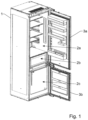
- Fig.1 shows a cooling device in the form of a refrigerator with a housing 1 and a usable space 2, which is divided into a cooling compartment 2a, a cold storage compartment 2b and a freezer compartment 2c.
- the device can, for example, be designed to maintain a temperature of greater than 0°C and less than 10°C in the refrigerator compartment, a temperature of greater than -2°C and less than 3°C in the cold storage compartment and a temperature of less than -18°C in the freezer compartment.
- two separate doors 3a, 3b are provided, but the use of a common door is also conceivable.
- the three utility spaces 2a, 2b and 2c are arranged vertically one above the other.
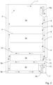
- a cooling device in the form of a refrigerator is shown with a housing 1 and two compartments 2a and 2b.
- the compartment 2a is a cooling compartment and the compartment 2b is a cold storage compartment.
- the cooling compartment 2a is divided into several compartments by means of three shelves 4.
- the cold storage compartment 2b is divided into two compartments by means of drawers 5a and 5b.
- the refrigerator also comprises a door 3 on the front, a first fan 6a, a second fan 6b, a cooling air duct 7 running along the back of the refrigerator and an evaporator 8, which is arranged in the cooling air duct 7.
- the first fan 6a is arranged in the upper area of the cooling air duct 7. It sucks air out of the cooling compartment 2a and conveys it downwards in the cooling air duct 7. As it flows through the cooling air duct 7, the air is cooled by the evaporator 8 arranged on the rear of the refrigerator.
- Four diagonal arrows 9 illustrate openings on the rear wall 10 of the cooling compartment 2a through which cooled air flows from the cooling air duct 7 into the various compartments of the cooling compartment 2a. Further cooled air flows downwards in the cooling air duct 7 towards the cold storage compartment 2b.
- the air flow is significantly influenced by the second fan 6b.
- the second fan 6b sucks air from the cold storage compartment 2b from the front to the back into the cooling air duct 7. Sucking in air from the cold storage compartment 2b has the advantage that relatively warm air flows through the second fan 6b and therefore the risk of ice formation in the second fan 6b can be reduced.
- the warm air blown into the cooling air duct 7 by the second fan 6b flows upwards in the cooling air duct 7 and collides in a mixing zone 11 with the cold air flowing down from above and cooled by the evaporator 8.
- a mixture of warm and cold air then flows from back to front above the upper drawer 5a and between the two drawers 5a and 5b within the cold storage compartment.
- a portion of the air circulating within the cold storage compartment 2b flows along the front side of the partition wall 12, which separates the cooling compartment 2a and the cold storage compartment 2b from each other, upwards into the cooling compartment 2a and finally back to the first fan 6a.
- an air guide element 13 is arranged, which ensures that the air flowing from front to back below the lower drawer 5b flows through the second fan 6b into the cooling air duct 7. Above the air guide element 13, the air flows from the cooling air duct 7 from back to front between the drawers 5a and 5b.
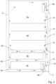
- FIG.3 A refrigerator is shown that has a compared to the one in Fig. 2 shown refrigerator has a different air flow.
- this embodiment there is less mixing of cooling air from the cooling compartment 2a and the cold storage compartment 2b. However, the mixing takes place again within the cooling air duct 7.
- the partition wall 12 is pulled all the way to the front within the usable space and thus lies flush against the door 3.
- the door 3 When the door 3 is closed, no air flows along the front of the partition wall 12 between the cooling compartment 2a and the cold storage compartment 2b.
- the cooling compartment 2a and the cold storage compartment 2b there is thus almost independent air circulation.
- Only in the mixing zone 11 in the cooling air duct 7 does air, which is conveyed from top to bottom by the first fan 6a in the cooling air duct 7, collide with air, which is conveyed from bottom to top by the second fan 6b in the cooling air duct 7.
- the mixing of air from the cooling compartment 2a and the cold storage compartment 2b is comparatively low. "No air” does not rule out the possibility that a small amount of air is flowing due to leaks.
- the evaporator 8 is pulled further down at the back. Below the lower drawer 5b, from front to back air to the second fan 6b. This blows the air into the cooling air duct 7, in which the air flows from bottom to top and between the partition wall 12 and the upper drawer 5a from back to front within the cold storage compartment 2b, so that the air circuit within the cold storage compartment 2b is closed.
Landscapes
- Engineering & Computer Science (AREA)
- Chemical & Material Sciences (AREA)
- Combustion & Propulsion (AREA)
- Physics & Mathematics (AREA)
- Mechanical Engineering (AREA)
- Thermal Sciences (AREA)
- General Engineering & Computer Science (AREA)
- Cold Air Circulating Systems And Constructional Details In Refrigerators (AREA)
Claims (7)
- Appareil de réfrigération comprenant- un espace utile (2a, 2b) avec un premier compartiment (2a), qui est conçu comme un compartiment de réfrigération, et un deuxième compartiment (2b), qui est conçu comme un compartiment de stockage froid, le deuxième compartiment (2b) étant disposé en dessous du premier compartiment (2a) et le premier compartiment (2a) et le deuxième compartiment (2b) étant séparés l'un de l'autre par une paroi de séparation horizontale (12),- une pompe à chaleur avec un évaporateur (8),- un canal d'air de refroidissement (7),- un premier ventilateur (6a) et un deuxième ventilateur (6b) pour transporter l'air dans le canal d'air de refroidissement (7), le premier ventilateur (6a) étant disposé derrière le premier compartiment (2a) et le deuxième ventilateur (6b) étant disposé derrière le deuxième compartiment (2b), le deuxième ventilateur (6b) étant disposé en dessous de la paroi de séparation horizontale (12),caractérisé en ce que le premier ventilateur (6a), le deuxième ventilateur (6b) et le canal d'air de refroidissement (7) sont disposés et configurés de telle sorte que le premier ventilateur (6a) transporte l'air dans le canal d'air de refroidissement (7) de haut en bas et le deuxième ventilateur (6b) transporte l'air dans le canal d'air de refroidissement (7) de bas en haut, c'est-à-dire dans le canal d'air de refroidissement (7) dans des directions opposées, de telle sorte que l'air refoulé par le premier ventilateur et l'air refoulé par le deuxième ventilateur entrent en collision frontale dans le canal d'air de refroidissement.
- Appareil de refroidissement selon la revendication 1, dans lequel l'évaporateur (8) est disposé dans le canal d'air de refroidissement (2) et/ou
l'évaporateur (8) s'étend au moins partiellement le long à la fois du premier (2a) et du deuxième (2b) compartiment. - Appareil de réfrigération selon l'une des revendications précédentes, dans lequel l'appareil de réfrigération comprend une porte (3) et la paroi de séparation horizontale (12) s'étend jusqu'à la porte (3), de telle sorte qu'aucun air ne circule entre la porte (3) et la paroi de séparation horizontale (12).
- Appareil de refroidissement selon l'une des revendications précédentes, dans lequel le premier ventilateur (6a), le deuxième ventilateur (6b) et le canal d'air de refroidissement (7) sont disposés et configurés de telle sorte que le premier ventilateur (6a) et le deuxième ventilateur (6b) transportent l'air dans le canal d'air de refroidissement (7) dans des directions opposées dans une section de canal continue, en particulier droite, en particulier verticale.
- Appareil de refroidissement selon l'une des revendications précédentes, dans lequel le canal d'air de refroidissement (7) est disposé derrière l'espace utile (2) et s'étend sensiblement verticalement.
- Appareil de refroidissement selon l'une des revendications précédentes, dans lequel le premier ventilateur (6a) et/ou le deuxième ventilateur (6b) sont disposés de manière à aspirer de l'air hors de l'espace utile (2), et en particulier- à souffler de l'air dans le canal d'air de refroidissement (7),- à transporter de l'air de l'avant vers l'arrière, et/ou- sont conçus comme des ventilateurs axiaux ou radiaux.
- Appareil de refroidissement selon l'une des revendications précédentes, dans lequel un élément de guidage d'air (13) est disposé directement au-dessus du deuxième ventilateur (6b) et le premier ventilateur (6a) et le deuxième ventilateur (6b) sont disposés de telle sorte que l'air s'écoule au-dessus de l'élément de guidage d'air (13) de l'arrière vers l'avant.
Applications Claiming Priority (1)
| Application Number | Priority Date | Filing Date | Title |
|---|---|---|---|
| CH11042019A CH714956A2 (de) | 2019-09-02 | 2019-09-02 | Kühlgerät mit entgegengesetzter Luftführung. |
Publications (2)
| Publication Number | Publication Date |
|---|---|
| EP3786552A1 EP3786552A1 (fr) | 2021-03-03 |
| EP3786552B1 true EP3786552B1 (fr) | 2024-09-25 |
Family
ID=68500172
Family Applications (1)
| Application Number | Title | Priority Date | Filing Date |
|---|---|---|---|
| EP20191760.6A Active EP3786552B1 (fr) | 2019-09-02 | 2020-08-19 | Appareil de refroidissement pourvu de conduit d'air opposé |
Country Status (2)
| Country | Link |
|---|---|
| EP (1) | EP3786552B1 (fr) |
| CH (1) | CH714956A2 (fr) |
Family Cites Families (8)
| Publication number | Priority date | Publication date | Assignee | Title |
|---|---|---|---|---|
| SU1551946A1 (ru) * | 1988-06-22 | 1990-03-23 | Всесоюзный Научно-Исследовательский, Конструкторско-Технологический Институт По Переработке Фруктов И Винограда | Установка дл замораживани продуктов |
| JPH0634251A (ja) * | 1992-07-14 | 1994-02-08 | Mitsubishi Electric Corp | 冷凍装置 |
| DE60230598D1 (de) | 2001-04-07 | 2009-02-12 | Lg Electronics Inc | Vorrichtung und verfahren zur steuerung eines kaltluftkreislaufs in einer kühlvorrichtung |
| DE202005005940U1 (de) | 2005-04-13 | 2006-08-24 | Liebherr-Hausgeräte Ochsenhausen GmbH | Kühl- und/oder Gefriergerät |
| JP2006300346A (ja) | 2005-04-15 | 2006-11-02 | Matsushita Electric Ind Co Ltd | 冷蔵庫 |
| PL2413074T3 (pl) * | 2010-07-26 | 2013-09-30 | Electrolux Home Products Corp Nv | Wielokomorowe urządzenie chłodnicze do przechowywania świeżej żywności w różnych temperaturach |
| KR20120071054A (ko) * | 2010-12-22 | 2012-07-02 | 삼성전자주식회사 | 냉장고 및 그 제어방법 |
| CN103930933B (zh) * | 2011-11-14 | 2016-09-14 | 富士电机株式会社 | 自动售货机 |
-
2019
- 2019-09-02 CH CH11042019A patent/CH714956A2/de unknown
-
2020
- 2020-08-19 EP EP20191760.6A patent/EP3786552B1/fr active Active
Also Published As
| Publication number | Publication date |
|---|---|
| EP3786552A1 (fr) | 2021-03-03 |
| CH714956A2 (de) | 2019-11-15 |
Similar Documents
| Publication | Publication Date | Title |
|---|---|---|
| EP2798285B1 (fr) | Appareil de froid à usage domestique comportant un compartiment fraîcheur | |
| WO2000049353A1 (fr) | Appareil frigorifique destine a etre encastre dans un meuble | |
| DE10203081B4 (de) | Kühlluftumwälzvorrichtung eines Kühlschranks | |
| DE19524845A1 (de) | Kühlschrank | |
| EP2224194B1 (fr) | Appareil de réfrigération et/ou de refroidissement | |
| EP1880152B1 (fr) | Appareil frigorifique | |
| EP3786552B1 (fr) | Appareil de refroidissement pourvu de conduit d'air opposé | |
| EP2434853A1 (fr) | Dispositif de climatisation destiné à refroidir de l'air pour une armoire d'instruments électroniques ou analogues | |
| EP3604988B1 (fr) | Appareil de réfrigération avec une pluralité de zones de température | |
| EP1327112B1 (fr) | Appareil de refrigeration | |
| EP2382429A1 (fr) | Appareil frigorifique a canal de circulation d'air | |
| DE102017005226A1 (de) | Sockelkonzept | |
| EP4066692B1 (fr) | Chambre froide pour la présentation de produits réfrigérés | |
| DE102005021560A1 (de) | Kältegerät mit Umluftkühlung | |
| DE102010055726A1 (de) | Kühl- und/oder Gefriergerät | |
| EP2096389A2 (fr) | Appareil de réfrigération et/ou de refroidissement | |
| DE19532728B4 (de) | Warenautomat mit unterteilbarem Warenraum | |
| DE19917974C2 (de) | Kühl- und/oder Gefriergerät mit einem im Innenraum angeordneten kältegenerierenden Bauteil | |
| EP2881687B1 (fr) | Appareil frigorifique | |
| DE102012012103A1 (de) | Kühl- und/oder Gefriergerät | |
| DE1946787C3 (de) | Kühltheke mit Umwälzung der Kühlluft | |
| EP2691711B1 (fr) | Appareil frigorifique à ventilateur axial | |
| DE102008054995A1 (de) | Kältegerät mit Luftfilter | |
| EP0727626A1 (fr) | Appareil frigorifique, notamment un réfrigérateur ménager | |
| EP4265985A1 (fr) | Appareil frigorifique ménager pourvu de deux évaporateurs |
Legal Events
| Date | Code | Title | Description |
|---|---|---|---|
| PUAI | Public reference made under article 153(3) epc to a published international application that has entered the european phase |
Free format text: ORIGINAL CODE: 0009012 |
|
| STAA | Information on the status of an ep patent application or granted ep patent |
Free format text: STATUS: THE APPLICATION HAS BEEN PUBLISHED |
|
| AK | Designated contracting states |
Kind code of ref document: A1 Designated state(s): AL AT BE BG CH CY CZ DE DK EE ES FI FR GB GR HR HU IE IS IT LI LT LU LV MC MK MT NL NO PL PT RO RS SE SI SK SM TR |
|
| AX | Request for extension of the european patent |
Extension state: BA ME |
|
| STAA | Information on the status of an ep patent application or granted ep patent |
Free format text: STATUS: REQUEST FOR EXAMINATION WAS MADE |
|
| 17P | Request for examination filed |
Effective date: 20210824 |
|
| RBV | Designated contracting states (corrected) |
Designated state(s): AL AT BE BG CH CY CZ DE DK EE ES FI FR GB GR HR HU IE IS IT LI LT LU LV MC MK MT NL NO PL PT RO RS SE SI SK SM TR |
|
| STAA | Information on the status of an ep patent application or granted ep patent |
Free format text: STATUS: EXAMINATION IS IN PROGRESS |
|
| 17Q | First examination report despatched |
Effective date: 20230206 |
|
| GRAP | Despatch of communication of intention to grant a patent |
Free format text: ORIGINAL CODE: EPIDOSNIGR1 |
|
| STAA | Information on the status of an ep patent application or granted ep patent |
Free format text: STATUS: GRANT OF PATENT IS INTENDED |
|
| INTG | Intention to grant announced |
Effective date: 20240517 |
|
| P01 | Opt-out of the competence of the unified patent court (upc) registered |
Free format text: CASE NUMBER: APP_37831/2024 Effective date: 20240625 |
|
| GRAS | Grant fee paid |
Free format text: ORIGINAL CODE: EPIDOSNIGR3 |
|
| GRAA | (expected) grant |
Free format text: ORIGINAL CODE: 0009210 |
|
| STAA | Information on the status of an ep patent application or granted ep patent |
Free format text: STATUS: THE PATENT HAS BEEN GRANTED |
|
| AK | Designated contracting states |
Kind code of ref document: B1 Designated state(s): AL AT BE BG CH CY CZ DE DK EE ES FI FR GB GR HR HU IE IS IT LI LT LU LV MC MK MT NL NO PL PT RO RS SE SI SK SM TR |
|
| REG | Reference to a national code |
Ref country code: GB Ref legal event code: FG4D Free format text: NOT ENGLISH |
|
| REG | Reference to a national code |
Ref country code: CH Ref legal event code: EP |
|
| REG | Reference to a national code |
Ref country code: DE Ref legal event code: R096 Ref document number: 502020009314 Country of ref document: DE |
|
| REG | Reference to a national code |
Ref country code: IE Ref legal event code: FG4D Free format text: LANGUAGE OF EP DOCUMENT: GERMAN |
|
| REG | Reference to a national code |
Ref country code: SE Ref legal event code: TRGR |
|
| REG | Reference to a national code |
Ref country code: LT Ref legal event code: MG9D |
|
| PG25 | Lapsed in a contracting state [announced via postgrant information from national office to epo] |
Ref country code: NO Free format text: LAPSE BECAUSE OF FAILURE TO SUBMIT A TRANSLATION OF THE DESCRIPTION OR TO PAY THE FEE WITHIN THE PRESCRIBED TIME-LIMIT Effective date: 20241225 |
|
| PG25 | Lapsed in a contracting state [announced via postgrant information from national office to epo] |
Ref country code: GR Free format text: LAPSE BECAUSE OF FAILURE TO SUBMIT A TRANSLATION OF THE DESCRIPTION OR TO PAY THE FEE WITHIN THE PRESCRIBED TIME-LIMIT Effective date: 20241226 Ref country code: FI Free format text: LAPSE BECAUSE OF FAILURE TO SUBMIT A TRANSLATION OF THE DESCRIPTION OR TO PAY THE FEE WITHIN THE PRESCRIBED TIME-LIMIT Effective date: 20240925 |
|
| PG25 | Lapsed in a contracting state [announced via postgrant information from national office to epo] |
Ref country code: BG Free format text: LAPSE BECAUSE OF FAILURE TO SUBMIT A TRANSLATION OF THE DESCRIPTION OR TO PAY THE FEE WITHIN THE PRESCRIBED TIME-LIMIT Effective date: 20240925 |
|
| PG25 | Lapsed in a contracting state [announced via postgrant information from national office to epo] |
Ref country code: LV Free format text: LAPSE BECAUSE OF FAILURE TO SUBMIT A TRANSLATION OF THE DESCRIPTION OR TO PAY THE FEE WITHIN THE PRESCRIBED TIME-LIMIT Effective date: 20240925 |
|
| PG25 | Lapsed in a contracting state [announced via postgrant information from national office to epo] |
Ref country code: RS Free format text: LAPSE BECAUSE OF FAILURE TO SUBMIT A TRANSLATION OF THE DESCRIPTION OR TO PAY THE FEE WITHIN THE PRESCRIBED TIME-LIMIT Effective date: 20241225 |
|
| REG | Reference to a national code |
Ref country code: NL Ref legal event code: MP Effective date: 20240925 |
|
| PG25 | Lapsed in a contracting state [announced via postgrant information from national office to epo] |
Ref country code: RS Free format text: LAPSE BECAUSE OF FAILURE TO SUBMIT A TRANSLATION OF THE DESCRIPTION OR TO PAY THE FEE WITHIN THE PRESCRIBED TIME-LIMIT Effective date: 20241225 Ref country code: NO Free format text: LAPSE BECAUSE OF FAILURE TO SUBMIT A TRANSLATION OF THE DESCRIPTION OR TO PAY THE FEE WITHIN THE PRESCRIBED TIME-LIMIT Effective date: 20241225 Ref country code: LV Free format text: LAPSE BECAUSE OF FAILURE TO SUBMIT A TRANSLATION OF THE DESCRIPTION OR TO PAY THE FEE WITHIN THE PRESCRIBED TIME-LIMIT Effective date: 20240925 Ref country code: GR Free format text: LAPSE BECAUSE OF FAILURE TO SUBMIT A TRANSLATION OF THE DESCRIPTION OR TO PAY THE FEE WITHIN THE PRESCRIBED TIME-LIMIT Effective date: 20241226 Ref country code: FI Free format text: LAPSE BECAUSE OF FAILURE TO SUBMIT A TRANSLATION OF THE DESCRIPTION OR TO PAY THE FEE WITHIN THE PRESCRIBED TIME-LIMIT Effective date: 20240925 Ref country code: BG Free format text: LAPSE BECAUSE OF FAILURE TO SUBMIT A TRANSLATION OF THE DESCRIPTION OR TO PAY THE FEE WITHIN THE PRESCRIBED TIME-LIMIT Effective date: 20240925 |
|
| PG25 | Lapsed in a contracting state [announced via postgrant information from national office to epo] |
Ref country code: NL Free format text: LAPSE BECAUSE OF FAILURE TO SUBMIT A TRANSLATION OF THE DESCRIPTION OR TO PAY THE FEE WITHIN THE PRESCRIBED TIME-LIMIT Effective date: 20240925 |
|
| PG25 | Lapsed in a contracting state [announced via postgrant information from national office to epo] |
Ref country code: IS Free format text: LAPSE BECAUSE OF FAILURE TO SUBMIT A TRANSLATION OF THE DESCRIPTION OR TO PAY THE FEE WITHIN THE PRESCRIBED TIME-LIMIT Effective date: 20250125 Ref country code: PT Free format text: LAPSE BECAUSE OF FAILURE TO SUBMIT A TRANSLATION OF THE DESCRIPTION OR TO PAY THE FEE WITHIN THE PRESCRIBED TIME-LIMIT Effective date: 20250127 |
|
| PG25 | Lapsed in a contracting state [announced via postgrant information from national office to epo] |
Ref country code: SM Free format text: LAPSE BECAUSE OF FAILURE TO SUBMIT A TRANSLATION OF THE DESCRIPTION OR TO PAY THE FEE WITHIN THE PRESCRIBED TIME-LIMIT Effective date: 20240925 Ref country code: RO Free format text: LAPSE BECAUSE OF FAILURE TO SUBMIT A TRANSLATION OF THE DESCRIPTION OR TO PAY THE FEE WITHIN THE PRESCRIBED TIME-LIMIT Effective date: 20240925 |
|
| PG25 | Lapsed in a contracting state [announced via postgrant information from national office to epo] |
Ref country code: ES Free format text: LAPSE BECAUSE OF FAILURE TO SUBMIT A TRANSLATION OF THE DESCRIPTION OR TO PAY THE FEE WITHIN THE PRESCRIBED TIME-LIMIT Effective date: 20240925 |
|
| PG25 | Lapsed in a contracting state [announced via postgrant information from national office to epo] |
Ref country code: EE Free format text: LAPSE BECAUSE OF FAILURE TO SUBMIT A TRANSLATION OF THE DESCRIPTION OR TO PAY THE FEE WITHIN THE PRESCRIBED TIME-LIMIT Effective date: 20240925 |
|
| PG25 | Lapsed in a contracting state [announced via postgrant information from national office to epo] |
Ref country code: CZ Free format text: LAPSE BECAUSE OF FAILURE TO SUBMIT A TRANSLATION OF THE DESCRIPTION OR TO PAY THE FEE WITHIN THE PRESCRIBED TIME-LIMIT Effective date: 20240925 Ref country code: PL Free format text: LAPSE BECAUSE OF FAILURE TO SUBMIT A TRANSLATION OF THE DESCRIPTION OR TO PAY THE FEE WITHIN THE PRESCRIBED TIME-LIMIT Effective date: 20240925 |
|
| PG25 | Lapsed in a contracting state [announced via postgrant information from national office to epo] |
Ref country code: SK Free format text: LAPSE BECAUSE OF FAILURE TO SUBMIT A TRANSLATION OF THE DESCRIPTION OR TO PAY THE FEE WITHIN THE PRESCRIBED TIME-LIMIT Effective date: 20240925 Ref country code: IT Free format text: LAPSE BECAUSE OF FAILURE TO SUBMIT A TRANSLATION OF THE DESCRIPTION OR TO PAY THE FEE WITHIN THE PRESCRIBED TIME-LIMIT Effective date: 20240925 |
|
| REG | Reference to a national code |
Ref country code: DE Ref legal event code: R097 Ref document number: 502020009314 Country of ref document: DE |
|
| PG25 | Lapsed in a contracting state [announced via postgrant information from national office to epo] |
Ref country code: DK Free format text: LAPSE BECAUSE OF FAILURE TO SUBMIT A TRANSLATION OF THE DESCRIPTION OR TO PAY THE FEE WITHIN THE PRESCRIBED TIME-LIMIT Effective date: 20240925 |
|
| PLBE | No opposition filed within time limit |
Free format text: ORIGINAL CODE: 0009261 |
|
| STAA | Information on the status of an ep patent application or granted ep patent |
Free format text: STATUS: NO OPPOSITION FILED WITHIN TIME LIMIT |
|
| 26N | No opposition filed |
Effective date: 20250626 |
|
| PGFP | Annual fee paid to national office [announced via postgrant information from national office to epo] |
Ref country code: DE Payment date: 20250820 Year of fee payment: 6 |
|
| PGFP | Annual fee paid to national office [announced via postgrant information from national office to epo] |
Ref country code: CH Payment date: 20250901 Year of fee payment: 6 Ref country code: SE Payment date: 20250820 Year of fee payment: 6 |
|
| PG25 | Lapsed in a contracting state [announced via postgrant information from national office to epo] |
Ref country code: HR Free format text: LAPSE BECAUSE OF FAILURE TO SUBMIT A TRANSLATION OF THE DESCRIPTION OR TO PAY THE FEE WITHIN THE PRESCRIBED TIME-LIMIT Effective date: 20240925 |
|
| REG | Reference to a national code |
Ref country code: DE Ref legal event code: R082 Ref document number: 502020009314 Country of ref document: DE Representative=s name: HOFFMANN EITLE PATENT- UND RECHTSANWAELTE PART, DE |
|
| PG25 | Lapsed in a contracting state [announced via postgrant information from national office to epo] |
Ref country code: MC Free format text: LAPSE BECAUSE OF FAILURE TO SUBMIT A TRANSLATION OF THE DESCRIPTION OR TO PAY THE FEE WITHIN THE PRESCRIBED TIME-LIMIT Effective date: 20240925 |
|
| PG25 | Lapsed in a contracting state [announced via postgrant information from national office to epo] |
Ref country code: LU Free format text: LAPSE BECAUSE OF NON-PAYMENT OF DUE FEES Effective date: 20250819 |