EP3786552B1 - Refrigerator with opposing air flow - Google Patents
Refrigerator with opposing air flow Download PDFInfo
- Publication number
- EP3786552B1 EP3786552B1 EP20191760.6A EP20191760A EP3786552B1 EP 3786552 B1 EP3786552 B1 EP 3786552B1 EP 20191760 A EP20191760 A EP 20191760A EP 3786552 B1 EP3786552 B1 EP 3786552B1
- Authority
- EP
- European Patent Office
- Prior art keywords
- fan
- cooling
- air
- compartment
- air duct
- Prior art date
- Legal status (The legal status is an assumption and is not a legal conclusion. Google has not performed a legal analysis and makes no representation as to the accuracy of the status listed.)
- Active
Links
Images
Classifications
-
- F—MECHANICAL ENGINEERING; LIGHTING; HEATING; WEAPONS; BLASTING
- F25—REFRIGERATION OR COOLING; COMBINED HEATING AND REFRIGERATION SYSTEMS; HEAT PUMP SYSTEMS; MANUFACTURE OR STORAGE OF ICE; LIQUEFACTION SOLIDIFICATION OF GASES
- F25D—REFRIGERATORS; COLD ROOMS; ICE-BOXES; COOLING OR FREEZING APPARATUS NOT OTHERWISE PROVIDED FOR
- F25D11/00—Self-contained movable devices, e.g. domestic refrigerators
- F25D11/02—Self-contained movable devices, e.g. domestic refrigerators with cooling compartments at different temperatures
-
- F—MECHANICAL ENGINEERING; LIGHTING; HEATING; WEAPONS; BLASTING
- F25—REFRIGERATION OR COOLING; COMBINED HEATING AND REFRIGERATION SYSTEMS; HEAT PUMP SYSTEMS; MANUFACTURE OR STORAGE OF ICE; LIQUEFACTION SOLIDIFICATION OF GASES
- F25D—REFRIGERATORS; COLD ROOMS; ICE-BOXES; COOLING OR FREEZING APPARATUS NOT OTHERWISE PROVIDED FOR
- F25D17/00—Arrangements for circulating cooling fluids; Arrangements for circulating gas, e.g. air, within refrigerated spaces
- F25D17/04—Arrangements for circulating cooling fluids; Arrangements for circulating gas, e.g. air, within refrigerated spaces for circulating air, e.g. by convection
- F25D17/06—Arrangements for circulating cooling fluids; Arrangements for circulating gas, e.g. air, within refrigerated spaces for circulating air, e.g. by convection by forced circulation
- F25D17/062—Arrangements for circulating cooling fluids; Arrangements for circulating gas, e.g. air, within refrigerated spaces for circulating air, e.g. by convection by forced circulation in household refrigerators
- F25D17/065—Arrangements for circulating cooling fluids; Arrangements for circulating gas, e.g. air, within refrigerated spaces for circulating air, e.g. by convection by forced circulation in household refrigerators with compartments at different temperatures
-
- F—MECHANICAL ENGINEERING; LIGHTING; HEATING; WEAPONS; BLASTING
- F25—REFRIGERATION OR COOLING; COMBINED HEATING AND REFRIGERATION SYSTEMS; HEAT PUMP SYSTEMS; MANUFACTURE OR STORAGE OF ICE; LIQUEFACTION SOLIDIFICATION OF GASES
- F25D—REFRIGERATORS; COLD ROOMS; ICE-BOXES; COOLING OR FREEZING APPARATUS NOT OTHERWISE PROVIDED FOR
- F25D17/00—Arrangements for circulating cooling fluids; Arrangements for circulating gas, e.g. air, within refrigerated spaces
- F25D17/04—Arrangements for circulating cooling fluids; Arrangements for circulating gas, e.g. air, within refrigerated spaces for circulating air, e.g. by convection
- F25D17/06—Arrangements for circulating cooling fluids; Arrangements for circulating gas, e.g. air, within refrigerated spaces for circulating air, e.g. by convection by forced circulation
- F25D17/062—Arrangements for circulating cooling fluids; Arrangements for circulating gas, e.g. air, within refrigerated spaces for circulating air, e.g. by convection by forced circulation in household refrigerators
-
- F—MECHANICAL ENGINEERING; LIGHTING; HEATING; WEAPONS; BLASTING
- F25—REFRIGERATION OR COOLING; COMBINED HEATING AND REFRIGERATION SYSTEMS; HEAT PUMP SYSTEMS; MANUFACTURE OR STORAGE OF ICE; LIQUEFACTION SOLIDIFICATION OF GASES
- F25D—REFRIGERATORS; COLD ROOMS; ICE-BOXES; COOLING OR FREEZING APPARATUS NOT OTHERWISE PROVIDED FOR
- F25D17/00—Arrangements for circulating cooling fluids; Arrangements for circulating gas, e.g. air, within refrigerated spaces
- F25D17/04—Arrangements for circulating cooling fluids; Arrangements for circulating gas, e.g. air, within refrigerated spaces for circulating air, e.g. by convection
- F25D17/06—Arrangements for circulating cooling fluids; Arrangements for circulating gas, e.g. air, within refrigerated spaces for circulating air, e.g. by convection by forced circulation
- F25D17/08—Arrangements for circulating cooling fluids; Arrangements for circulating gas, e.g. air, within refrigerated spaces for circulating air, e.g. by convection by forced circulation using ducts
-
- F—MECHANICAL ENGINEERING; LIGHTING; HEATING; WEAPONS; BLASTING
- F25—REFRIGERATION OR COOLING; COMBINED HEATING AND REFRIGERATION SYSTEMS; HEAT PUMP SYSTEMS; MANUFACTURE OR STORAGE OF ICE; LIQUEFACTION SOLIDIFICATION OF GASES
- F25D—REFRIGERATORS; COLD ROOMS; ICE-BOXES; COOLING OR FREEZING APPARATUS NOT OTHERWISE PROVIDED FOR
- F25D2317/00—Details or arrangements for circulating cooling fluids; Details or arrangements for circulating gas, e.g. air, within refrigerated spaces, not provided for in other groups of this subclass
- F25D2317/06—Details or arrangements for circulating cooling fluids; Details or arrangements for circulating gas, e.g. air, within refrigerated spaces, not provided for in other groups of this subclass with forced air circulation
- F25D2317/068—Details or arrangements for circulating cooling fluids; Details or arrangements for circulating gas, e.g. air, within refrigerated spaces, not provided for in other groups of this subclass with forced air circulation characterised by the fans
- F25D2317/0682—Two or more fans
-
- F—MECHANICAL ENGINEERING; LIGHTING; HEATING; WEAPONS; BLASTING
- F25—REFRIGERATION OR COOLING; COMBINED HEATING AND REFRIGERATION SYSTEMS; HEAT PUMP SYSTEMS; MANUFACTURE OR STORAGE OF ICE; LIQUEFACTION SOLIDIFICATION OF GASES
- F25D—REFRIGERATORS; COLD ROOMS; ICE-BOXES; COOLING OR FREEZING APPARATUS NOT OTHERWISE PROVIDED FOR
- F25D2400/00—General features of, or devices for refrigerators, cold rooms, ice-boxes, or for cooling or freezing apparatus not covered by any other subclass
- F25D2400/04—Refrigerators with a horizontal mullion
Definitions
- the invention relates to a cooling device, in particular a refrigerator, with a usable space, a heat pump with an evaporator, a cooling air duct and a first and a second fan to convey air in the cooling air duct.
- WO 02/081 987 shows a refrigerator with a refrigerator compartment and a freezer compartment and two fans, whereby the first fan is arranged directly near the evaporator to convey the cooled air into the usable space.
- the second fan is arranged in the lower part of the refrigerator at the back of the usable space to improve the circulation of the air in the usable space. This ensures a more even temperature distribution within the usable space.
- JP2006 300 346 shows a cooling device with a number of compartments and with a cooling air duct arranged behind the compartments, in which an evaporator is arranged.
- a fan is arranged at all access openings through which air flows from the cooling air duct into the individual compartments. This allows the temperature in each compartment to be set individually and precisely.
- EP2413074 shows a cooling device with two fans.
- the first fan transports air from a first cooling compartment into a cooling air duct and the second fan transports air from the first cooling compartment into a second cooling compartment.
- the task is to provide a cooling device with improved air flow.
- the first fan, the second fan and the cooling air duct are arranged and designed such that the first fan and the second fan convey air in the cooling air duct in opposite directions.
- the air is conveyed in opposite directions such that the air conveyed by the first fan and the air conveyed by the second fan collide head-on in the cooling air duct.
- This air flow has the advantage that the air is distributed as evenly as possible within the usable space and the temperature within the usable space can be controlled as precisely as possible. Ice formation in the fans should also be prevented as best as possible.
- the usable space comprises a first and a second compartment, wherein the second compartment is a cold storage compartment and the second compartment is arranged below the first compartment and the first compartment and the second compartment are separated from each other by a horizontal partition wall.
- a "cold storage compartment” is a compartment in which temperatures of approximately -2°C and +3°C are maintained.
- the partition can completely separate the compartments from each other or have a passage through which air can flow from the first compartment into the second compartment or from the second compartment into the first compartment.
- the first fan is located behind the first compartment and the second fan is located behind the second compartment, with the second fan located below the horizontal divider.
- the first fan, the second fan and the cooling air duct are arranged and designed such that the first fan and the second fan convey the air in the cooling air duct in opposite directions in a continuous, in particular straight, in particular vertical, duct section.
- a cooling device can comprise several cooling air ducts, but the opposing air flow occurs in a single connected cooling air duct.
- the cooling air duct is arranged behind the usable space and the cooling air duct runs essentially vertically.
- Behind is to be viewed from the usual perspective of a user of a cooling device.
- the door forms the front.
- the usable space is located behind the door and the cooling air duct is located behind the usable space, in particular at the back of the cooling device.
- the advantage of sucking in air from the usable space is that the air flowing through the fan is relatively warm and therefore ice formation on the fan can be prevented.
- the evaporator extends at least partially along the first compartment as well as at least partially along the second compartment.
- An air guide element can be arranged immediately above the second fan and the first fan and the second fan can be arranged such that the air above the air guide element flows from the back to the front.
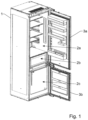
- Fig.1 shows a cooling device in the form of a refrigerator with a housing 1 and a usable space 2, which is divided into a cooling compartment 2a, a cold storage compartment 2b and a freezer compartment 2c.
- the device can, for example, be designed to maintain a temperature of greater than 0°C and less than 10°C in the refrigerator compartment, a temperature of greater than -2°C and less than 3°C in the cold storage compartment and a temperature of less than -18°C in the freezer compartment.
- two separate doors 3a, 3b are provided, but the use of a common door is also conceivable.
- the three utility spaces 2a, 2b and 2c are arranged vertically one above the other.
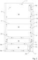
- a cooling device in the form of a refrigerator is shown with a housing 1 and two compartments 2a and 2b.
- the compartment 2a is a cooling compartment and the compartment 2b is a cold storage compartment.
- the cooling compartment 2a is divided into several compartments by means of three shelves 4.
- the cold storage compartment 2b is divided into two compartments by means of drawers 5a and 5b.
- the refrigerator also comprises a door 3 on the front, a first fan 6a, a second fan 6b, a cooling air duct 7 running along the back of the refrigerator and an evaporator 8, which is arranged in the cooling air duct 7.
- the first fan 6a is arranged in the upper area of the cooling air duct 7. It sucks air out of the cooling compartment 2a and conveys it downwards in the cooling air duct 7. As it flows through the cooling air duct 7, the air is cooled by the evaporator 8 arranged on the rear of the refrigerator.
- Four diagonal arrows 9 illustrate openings on the rear wall 10 of the cooling compartment 2a through which cooled air flows from the cooling air duct 7 into the various compartments of the cooling compartment 2a. Further cooled air flows downwards in the cooling air duct 7 towards the cold storage compartment 2b.
- the air flow is significantly influenced by the second fan 6b.
- the second fan 6b sucks air from the cold storage compartment 2b from the front to the back into the cooling air duct 7. Sucking in air from the cold storage compartment 2b has the advantage that relatively warm air flows through the second fan 6b and therefore the risk of ice formation in the second fan 6b can be reduced.
- the warm air blown into the cooling air duct 7 by the second fan 6b flows upwards in the cooling air duct 7 and collides in a mixing zone 11 with the cold air flowing down from above and cooled by the evaporator 8.
- a mixture of warm and cold air then flows from back to front above the upper drawer 5a and between the two drawers 5a and 5b within the cold storage compartment.
- a portion of the air circulating within the cold storage compartment 2b flows along the front side of the partition wall 12, which separates the cooling compartment 2a and the cold storage compartment 2b from each other, upwards into the cooling compartment 2a and finally back to the first fan 6a.
- an air guide element 13 is arranged, which ensures that the air flowing from front to back below the lower drawer 5b flows through the second fan 6b into the cooling air duct 7. Above the air guide element 13, the air flows from the cooling air duct 7 from back to front between the drawers 5a and 5b.
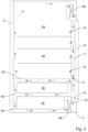
- FIG.3 A refrigerator is shown that has a compared to the one in Fig. 2 shown refrigerator has a different air flow.
- this embodiment there is less mixing of cooling air from the cooling compartment 2a and the cold storage compartment 2b. However, the mixing takes place again within the cooling air duct 7.
- the partition wall 12 is pulled all the way to the front within the usable space and thus lies flush against the door 3.
- the door 3 When the door 3 is closed, no air flows along the front of the partition wall 12 between the cooling compartment 2a and the cold storage compartment 2b.
- the cooling compartment 2a and the cold storage compartment 2b there is thus almost independent air circulation.
- Only in the mixing zone 11 in the cooling air duct 7 does air, which is conveyed from top to bottom by the first fan 6a in the cooling air duct 7, collide with air, which is conveyed from bottom to top by the second fan 6b in the cooling air duct 7.
- the mixing of air from the cooling compartment 2a and the cold storage compartment 2b is comparatively low. "No air” does not rule out the possibility that a small amount of air is flowing due to leaks.
- the evaporator 8 is pulled further down at the back. Below the lower drawer 5b, from front to back air to the second fan 6b. This blows the air into the cooling air duct 7, in which the air flows from bottom to top and between the partition wall 12 and the upper drawer 5a from back to front within the cold storage compartment 2b, so that the air circuit within the cold storage compartment 2b is closed.
Landscapes
- Engineering & Computer Science (AREA)
- Chemical & Material Sciences (AREA)
- Combustion & Propulsion (AREA)
- Physics & Mathematics (AREA)
- Mechanical Engineering (AREA)
- Thermal Sciences (AREA)
- General Engineering & Computer Science (AREA)
- Cold Air Circulating Systems And Constructional Details In Refrigerators (AREA)
Description
Die Erfindung betrifft ein Kühlgerät, insbesondere einen Kühlschrank, mit einem Nutzraum, einer Wärmepumpe mit einem Verdampfer, einem Kühlluftkanal und einem ersten und einem zweiten Lüfter, um Luft im Kühlluftkanal zu fördern.The invention relates to a cooling device, in particular a refrigerator, with a usable space, a heat pump with an evaporator, a cooling air duct and a first and a second fan to convey air in the cooling air duct.
In
Es stellt sich die Aufgabe, ein Kühlgerät mit einer verbesserten Luftführung bereitzustellen.The task is to provide a cooling device with improved air flow.
Diese Aufgabe wird durch den Gegenstand der unabhängigen Patentansprüche gelöst.This problem is solved by the subject matter of the independent patent claims.
Demgemäss umfasst das Kühlgerät zumindest die folgenden Elemente:
- Einen Nutzraum: Dieser dient der Lagerung des Kühlguts. Dabei kann es sich insbesondere um Lebensmittel handeln. Es können jedoch auch andere Objekte gekühlt werden, wie z.B. Medikamente, medizinische Proben, Chemikalien usw.
- Eine Wärmepumpe mit einem Verdampfer: Beim Verdampfer kann es sich um den einzigen Verdampfer handeln, oder es kann zusätzlich noch mindestens ein zweiter Verdampfer vorgesehen sein.
- Einen Kühlluftkanal: ein Kanal, durch welchen Luft in und aus dem Nutzraum befördert wird. Innerhalb des Kühlluftkanals kann vom Benutzer kein Kühlgut angeordnet werden. Bevorzugterweise ist der Verdampfer innerhalb des Kühlluftkanals angeordnet.
- Einen ersten Lüfter und einen zweiten Lüfter, um Luft im Kühlluftkanal zu fördern.
- A usable space: This is used to store the goods to be cooled. This can be food in particular. However, other objects can also be cooled, such as medicines, medical samples, chemicals, etc.
- A heat pump with an evaporator: The evaporator can be the only evaporator, or there can be at least one second evaporator in addition.
- A cooling air duct: a duct through which air is transported in and out of the usable space. The user cannot place any cooled goods within the cooling air duct. The evaporator is preferably arranged within the cooling air duct.
- A first fan and a second fan to move air in the cooling air duct.
Der erste Lüfter, der zweite Lüfter und der Kühlluftkanal sind derart angeordnet und ausgestaltet, dass der erste Lüfter und der zweite Lüfter Luft im Kühlluftkanal in entgegengesetzter Richtung fördern. Die Luft wird derart entgegengesetzt gefördert, dass die vom ersten Lüfter geförderte Luft und die vom zweiten Lüfter geförderte Luft im Kühlluftkanal frontal aufeinander prallen.The first fan, the second fan and the cooling air duct are arranged and designed such that the first fan and the second fan convey air in the cooling air duct in opposite directions. The air is conveyed in opposite directions such that the air conveyed by the first fan and the air conveyed by the second fan collide head-on in the cooling air duct.
Diese Luftführung hat den Vorteil, dass die Luft innerhalb des Nutzraums möglichst gleichmässig verteilt und die Temperatur innerhalb des Nutzraums möglichst präzise gesteuert werden kann. Im Weiteren kann auch in den Lüftern die Eisbildung möglichst gut verhindert werden.This air flow has the advantage that the air is distributed as evenly as possible within the usable space and the temperature within the usable space can be controlled as precisely as possible. Ice formation in the fans should also be prevented as best as possible.
Der erste Lüfter, der zweite Lüfter und der Kühlluftkanal sind derart angeordnet, dass der erste Lüfter die Luft im Kühlluftkanal von oben nach unten und der zweite Lüfter die Luft im Kühlluftkanal von unten nach oben fördern.The first fan, the second fan and the cooling air duct are arranged such that the first fan moves the air in the cooling air duct from top to bottom and the second fan moves the air in the cooling air duct from bottom to top.
Der Nutzraum umfasst ein erstes und ein zweites Fach, wobei das zweite Fach ein Kaltlagerfach ist und das zweite Fach unterhalb des ersten Faches angeordnet ist und das erste Fach und das zweite Fach durch eine horizontale Trennwand voneinander getrennt sind.The usable space comprises a first and a second compartment, wherein the second compartment is a cold storage compartment and the second compartment is arranged below the first compartment and the first compartment and the second compartment are separated from each other by a horizontal partition wall.
Ein "Kaltlagerfach" ist ein Fach, in welchem Temperaturen von ca. -2°C und +3°C gehalten werden. Die Trennwand kann die Fächer vollständig voneinander trennen oder auch einen Durchlass aufweisen, durch welchen Luft vom ersten Fach in das zweite Fach oder vom zweiten Fach in das erste Fach strömen kann.A "cold storage compartment" is a compartment in which temperatures of approximately -2°C and +3°C are maintained. The partition can completely separate the compartments from each other or have a passage through which air can flow from the first compartment into the second compartment or from the second compartment into the first compartment.
Der erste Lüfter ist hinter dem ersten Fach und der zweite Lüfter hinter dem zweiten Fach angeordnet, wobei der zweite Lüfter unterhalb der horizontalen Trennwand angeordnet ist.The first fan is located behind the first compartment and the second fan is located behind the second compartment, with the second fan located below the horizontal divider.
In einer besonderen Ausführungsform sind der erste Lüfter, der zweite Lüfter und der Kühlluftkanal derart angeordnet und ausgestaltet, dass der erste Lüfter und der zweite Lüfter die Luft im Kühlluftkanal in einem zusammenhängenden, insbesondere gerade verlaufenden, insbesondere vertikal verlaufenden, Kanalabschnitt in entgegengesetzter Richtung fördern.In a particular embodiment, the first fan, the second fan and the cooling air duct are arranged and designed such that the first fan and the second fan convey the air in the cooling air duct in opposite directions in a continuous, in particular straight, in particular vertical, duct section.
Damit soll klargestellt werden, dass ein Kühlgerät mehrere Kühlluftkanäle umfassen kann, die entgegengesetzte Luftströmung allerdings in einem einzelnen zusammenhängenden Kühlluftkanal erfolgt.This is to clarify that a cooling device can comprise several cooling air ducts, but the opposing air flow occurs in a single connected cooling air duct.
Dadurch erfolgt eine zumindest geringfügige Durchmischung der vom ersten Lüfter geförderten Luft mit der vom zweiten Lüfter geförderten Luft innerhalb des Kühlluftkanals. Das Aufeinanderprallen der Luft hat eine luftleitende Wirkung und es kann insbesondere eine Durchmischung von mit dem Verdampfer gekühlter Luft und aus dem Nutzraum angesaugter Luft erreicht werden, sodass durch Steuerung des ersten und des zweiten Lüfters durch Zusammenführung von kalter, aus dem Verdampfer stammenden Luft und warmer, aus dem Nutzraum gesaugter Luft eine gezielt temperierte Luft in den Nutzraum eingeströmt werden kann.This results in at least a slight mixing of the air conveyed by the first fan with the air conveyed by the second fan within the cooling air duct. The collision of the air has an air-conducting effect and in particular a mixing of air cooled by the evaporator and from The air drawn in from the usable space can be controlled so that by controlling the first and second fans, a specifically tempered air can be flowed into the usable space by combining cold air from the evaporator and warm air drawn in from the usable space.
Mit Vorteil ist der Kühlluftkanal hinter dem Nutzraum angeordnet und der Kühlluftkanal verläuft im Wesentlichen vertikal.Advantageously, the cooling air duct is arranged behind the usable space and the cooling air duct runs essentially vertically.
"hinter" ist aus der üblichen Perspektive eines Benutzers eines Kühlgeräts zu betrachten. Insbesondere bei einem Kühlschrank bildet die Türe die Frontseite. Hinter der Türe ist der Nutzraum angeordnet und hinter dem Nutzraum, insbesondere an der Rückseite des Kühlgeräts ist der Kühlluftkanal angeordnet."Behind" is to be viewed from the usual perspective of a user of a cooling device. In the case of a refrigerator in particular, the door forms the front. The usable space is located behind the door and the cooling air duct is located behind the usable space, in particular at the back of the cooling device.
Mit Vorteil sind der erste Lüfter und/oder der zweite Lüfter derart angeordnet, dass sie Luft aus dem Nutzraum saugen, und
- Luft in den Kühlluftkanal einblasen,
- Luft von vorne nach hinten fördern, und/oder
- als Axial- oder Radiallüfter ausgestaltet sind.
- Blow air into the cooling air duct,
- Move air from front to back, and/or
- are designed as axial or radial fans.
Das Ansaugen von Luft aus dem Nutzraum hat den Vorteil, dass die durch den Lüfter strömende Luft verhältnismässig warm ist und deshalb eine Eisbildung am Lüfter verhindert werden kann.The advantage of sucking in air from the usable space is that the air flowing through the fan is relatively warm and therefore ice formation on the fan can be prevented.
Insbesondere erstreckt sich der Verdampfer sowohl mindestens teilweise entlang des ersten als auch mindestens teilweise entlang des zweiten Faches.In particular, the evaporator extends at least partially along the first compartment as well as at least partially along the second compartment.
Unmittelbar oberhalb des zweiten Lüfters kann ein Luftleitelement angeordnet sein und der erste Lüfter und der zweite Lüfter können derart angeordnet sein, dass die Luft oberhalb des Luftleitelements von hinten nach vorne strömt.An air guide element can be arranged immediately above the second fan and the first fan and the second fan can be arranged such that the air above the air guide element flows from the back to the front.
Weitere Ausgestaltungen, Vorteile und Anwendungen der Erfindung ergeben sich aus den abhängigen Ansprüchen und aus der nun folgenden Beschreibung anhand der Figuren. Dabei zeigen:
-
Fig. 1 ein Kühlgerät mit Kühlfach, Kaltlagerfach und Gefrierfach; -
Fig. 2 eine schematische Skizze eines Kühlgeräts mit Luftführung in einer ersten Variante; und -
Fig. 3 eine schematische Skizze eines Kühlgeräts mit Luftführung in einer zweiten Variante.
-
Fig.1 a refrigerator with a refrigerator compartment, cold storage compartment and freezer compartment; -
Fig. 2 a schematic sketch of a cooling device with air duct in a first variant; and -
Fig.3 a schematic sketch of a cooling device with air duct in a second variant.
Das Gerät kann z.B. dazu ausgestaltet sein, im Kühlfach eine Temperatur grösser 0°C und kleiner 10°C, im Kaltlagerfach eine Temperatur grösser -2°C und kleiner 3°C und im Gefrierfach eine Temperatur kleiner -18°C aufrechtzuerhalten.The device can, for example, be designed to maintain a temperature of greater than 0°C and less than 10°C in the refrigerator compartment, a temperature of greater than -2°C and less than 3°C in the cold storage compartment and a temperature of less than -18°C in the freezer compartment.
In der vorliegenden Ausführung sind zwei separate Türen 3a, 3b vorgesehen, denkbar ist jedoch auch die Verwendung einer gemeinsamen Türe.In the present embodiment, two
Mit Vorteil sind die drei Nutzräume 2a, 2b und 2c vertikal übereinander angeordnet.Advantageously, the three
In
Im Folgenden soll die Luftzirkulation innerhalb des Kühlschranks veranschaulicht werden. In der
Der erste Lüfter 6a ist im oberen Bereich des Kühlluftkanals 7 angeordnet. Er saugt Luft aus dem Kühlfach 2a und fördert sie im Kühlluftkanal 7 nach unten. Beim Durchströmen des Kühlluftkanals 7 wird die Luft von dem an der Rückseite des Kühlschranks angeordneten Verdampfer 8 abgekühlt. Vier schräge Pfeile 9 veranschaulichen Öffnungen an der Rückwand 10 des Kühlfaches 2a, durch welche abgekühlte Luft aus dem Kühlluftkanal 7 in die unterschiedlichen Kompartimente des Kühlfaches 2a einströmt. Weitere abgekühlte Luft strömt im Kühlluftkanal 7 nach unten in Richtung des Kaltlagerfaches 2b.The
Innerhalb des Kaltlagerfaches 2b wird die Luftströmung wesentlich durch den zweiten Lüfter 6b beeinflusst. Der zweite Lüfter 6b saugt Luft aus dem Kaltlagerfach 2b von vorne nach hinten in den Kühlluftkanal 7. Das Ansaugen von Luft aus dem Kaltlagerfach 2b hat den Vorteil, dass verhältnismässig warme Luft durch den zweiten Lüfter 6b strömt und deshalb das Risiko der Eisbildung im zweiten Lüfter 6b reduziert werden kann.Within the
Die vom zweiten Lüfter 6b in den Kühlluftkanal 7 eingeblasene, warme Luft strömt im Kühlluftkanal 7 nach oben und prallt in einer Mischzone 11 auf die von oben herabströmende, vom Verdampfer 8 abgekühlte kalte Luft. Eine Mischung aus warmer und kalter Luft strömt sodann oberhalb der oberen Schublade 5a und zwischen den beiden Schubladen 5a und 5b innerhalb des Kaltlagerfaches von hinten nach vorne. Durch Veränderung des Leistungsverhältnisses zwischen dem erste Lüfter 6a und dem zweiten Lüfter 6b kann die Temperatur und die Homogenität der Temperaturverteilung innerhalb des Kaltlagerfaches 2b gezielt gesteuert werden.The warm air blown into the cooling
Ein Teil der innerhalb des Kaltlagerfaches 2b zirkulierenden Luft strömt an der Frontseite der Trennwand 12, welche das Kühlfach 2a und das Kaltlagerfach 2b voneinander trennt, nach oben in das Kühlfach 2a und schlussendlich zurück zum ersten Lüfter 6a.A portion of the air circulating within the
Oberhalb des zweiten Lüfters 6b ist ein Luftleitelement 13 angeordnet, welches sicherstellt, dass die unterhalb der unteren Schublade 5b von vorne nach hinten strömende Luft durch den zweiten Lüfter 6b in den Kühlluftkanal 7 strömt. Oberhalb des Luftleitelements 13 strömt die Luft aus dem Kühlluftkanal 7 von hinten nach vorne zwischen den Schubladen 5a und 5b.Above the
In
Konstruktiv liegt ein Unterschied darin, dass die Trennwand 12 innerhalb des Nutzraums bis ganz nach vorne gezogen ist und damit bündig an die Türe 3 anliegt. Bei geschlossener Türe 3 strömt somit keine Luft an der Frontseite der Trennwand 12 zwischen dem Kühlfach 2a und dem Kaltlagerfach 2b. Im Kühlfach 2a und im Kaltlagerfach 2b findet somit eine beinahe eigenständige Luftzirkulation statt. Einzig in der Mischzone 11 im Kühlluftkanal 7 prallt Luft, welche vom ersten Lüfter 6a im Kühlluftkanal 7 von oben nach unten gefördert wird, auf Luft, welche vom zweiten Lüfter 6b im Kühlluftkanal 7 von unten nach oben gefördert wird. Die Durchmischung von Luft aus dem Kühlfach 2a und dem Kaltlagerfach 2b ist dabei aber vergleichsweise gering. "Keine Luft" schliesst nicht aus, dass aufgrund von undichten Stellen geringfügig Luft strömt.One structural difference is that the
Damit die im Kaltlagerfach 2b zirkulierende Luft abgekühlt wird, ist im Vergleich zum Kühlschrank gemäss
Claims (7)
- Refrigerating appliance comprising- a useful space (2a, 2b) with a first compartment (2a), which is designed as a cooling compartment, and a second compartment (2b), which is designed as a cold storage compartment, wherein the second compartment (2b) is arranged below the first compartment (2a) and the first compartment (2a) and the second compartment (2b) are separated from one another by a horizontal partition wall (12),- a heat pump with an evaporator (8),- a cooling air duct (7),- a first fan (6a) and a second fan (6b) for conveying air in the cooling air duct (7), the first fan (6a) being arranged behind the first compartment (2a) and the second fan (6b) being arranged behind the second compartment (2b), the second fan (6b) being arranged below the horizontal partition wall (12),characterised in that the first fan (6a), the second fan (6b) and the cooling air duct (7) are arranged and designed in such a way that the first fan (6a) directs the air in the cooling air duct (7) from top to bottom and the second fan (6b) directs the air in the cooling air duct (7) from bottom to top, i.e. in the cooling air duct (7) in the opposite direction, in such a way that the air conveyed by the first fan and the air conveyed by the second fan collide head-on in the cooling air duct.
- Cooling appliance according to claim 1, wherein the evaporator (8) is arranged in the cooling air duct (2) and/or
the evaporator (8) extends at least partially along both the first (2a) and the second (2b) compartment. - Cooling appliance according to any of the preceding claims, wherein the cooling appliance comprises a door (3) and the horizontal partition (12) extends up to the door (3) such that no air flows between the door (3) and the horizontal partition (12).
- Cooling appliance according to one of the preceding claims, wherein the first fan (6a), the second fan (6b) and the cooling air duct (7) are arranged and designed in such a way that the first fan (6a) and the second fan (6b) convey the air in the cooling air duct (7) in a continuous, in particular straight, in particular vertically extending duct section in opposite directions.
- Cooling appliance according to one of the preceding claims, wherein the cooling air duct (7) is arranged behind the useful space (2) and extends substantially vertically.
- Cooling appliance according to one of the preceding claims, wherein the first fan (6a) and/or the second fan (6b) are arranged such that they draw air from the usable space (2) and, in particular- blowing air into the cooling air duct (7),- convey air from the front to the rear, and/or- are designed as axial or radial fans.
- Cooling appliance according to one of the preceding claims, wherein an air guide element (13) is arranged directly above the second fan (6b) and the first fan (6a) and the second fan (6b) are arranged in such a way that the air flows above the air guide element (13) from the rear to the front.
Applications Claiming Priority (1)
| Application Number | Priority Date | Filing Date | Title |
|---|---|---|---|
| CH11042019A CH714956A2 (en) | 2019-09-02 | 2019-09-02 | Cooling unit with opposite air flow. |
Publications (2)
| Publication Number | Publication Date |
|---|---|
| EP3786552A1 EP3786552A1 (en) | 2021-03-03 |
| EP3786552B1 true EP3786552B1 (en) | 2024-09-25 |
Family
ID=68500172
Family Applications (1)
| Application Number | Title | Priority Date | Filing Date |
|---|---|---|---|
| EP20191760.6A Active EP3786552B1 (en) | 2019-09-02 | 2020-08-19 | Refrigerator with opposing air flow |
Country Status (2)
| Country | Link |
|---|---|
| EP (1) | EP3786552B1 (en) |
| CH (1) | CH714956A2 (en) |
Family Cites Families (8)
| Publication number | Priority date | Publication date | Assignee | Title |
|---|---|---|---|---|
| SU1551946A1 (en) * | 1988-06-22 | 1990-03-23 | Всесоюзный Научно-Исследовательский, Конструкторско-Технологический Институт По Переработке Фруктов И Винограда | Unit for freezing foodstuffs |
| JPH0634251A (en) * | 1992-07-14 | 1994-02-08 | Mitsubishi Electric Corp | Freezing device |
| DE60230598D1 (en) | 2001-04-07 | 2009-02-12 | Lg Electronics Inc | DEVICE AND METHOD FOR CONTROLLING A COLD AIR CIRCUIT IN A COOLING DEVICE |
| DE202005005940U1 (en) | 2005-04-13 | 2006-08-24 | Liebherr-Hausgeräte Ochsenhausen GmbH | A method for adjusting the flow of refrigerated air in a domestic refrigeration appliance has an air distribution duct with outlets in each compartment which may be closed independently |
| JP2006300346A (en) | 2005-04-15 | 2006-11-02 | Matsushita Electric Ind Co Ltd | refrigerator |
| PL2413074T3 (en) * | 2010-07-26 | 2013-09-30 | Electrolux Home Products Corp Nv | Multi-compartment refrigerating apparatus for storing fresh food at different temperatures |
| KR20120071054A (en) * | 2010-12-22 | 2012-07-02 | 삼성전자주식회사 | Refrigerator and control method thereof |
| CN103930933B (en) * | 2011-11-14 | 2016-09-14 | 富士电机株式会社 | Automatic vending machine |
-
2019
- 2019-09-02 CH CH11042019A patent/CH714956A2/en unknown
-
2020
- 2020-08-19 EP EP20191760.6A patent/EP3786552B1/en active Active
Also Published As
| Publication number | Publication date |
|---|---|
| EP3786552A1 (en) | 2021-03-03 |
| CH714956A2 (en) | 2019-11-15 |
Similar Documents
| Publication | Publication Date | Title |
|---|---|---|
| EP2798285B1 (en) | Domestic refrigeration device having a cold storage compartment | |
| WO2000049353A1 (en) | Refrigeration unit for fitting in a furniture recess | |
| DE10203081B4 (en) | Kühlluftumwälzvorrichtung a refrigerator | |
| DE19524845A1 (en) | fridge | |
| EP2224194B1 (en) | Refrigeration and/or freezer device | |
| EP1880152B1 (en) | Refrigerating device | |
| EP3786552B1 (en) | Refrigerator with opposing air flow | |
| EP2434853A1 (en) | Air conditioning device for cooling air for an electronics cabinet or similar | |
| EP3604988B1 (en) | Refrigeration apparatus with multiple temperature zones | |
| EP1327112B1 (en) | Refrigerating device | |
| EP2382429A1 (en) | Refrigeration unit having an air channel | |
| DE102017005226A1 (en) | base concept | |
| EP4066692B1 (en) | COOL ROOM FOR THE PRESENTATION OF CHILLED GOODS | |
| DE102005021560A1 (en) | Refrigeration unit with circulating air cooling | |
| DE102010055726A1 (en) | Refrigerating- and/or freezing device for cooling goods e.g. fruits, has ventilator arranged in cold storage shelf or partition wall such that ventilator guides air via shelf or partial area of shelf in switched on condition | |
| EP2096389A2 (en) | Refrigeration and/or freezer device | |
| DE19532728B4 (en) | Vending machine with subdividable goods space | |
| DE19917974C2 (en) | Refrigerator and / or freezer with a cold-generating component arranged in the interior | |
| EP2881687B1 (en) | Refrigeration device | |
| DE102012012103A1 (en) | Cooling- and/or freezing apparatus, has ventilator arranged in cool air region, which is separated into suction and pressure-side regions by ventilator and walls, where suction-side region extended into lateral portions of diaphragm | |
| DE1946787C3 (en) | Refrigerated counter with circulation of the cooling air | |
| EP2691711B1 (en) | Refrigerator having an axial fan | |
| DE102008054995A1 (en) | Household refrigerator, has air filter that is arranged in area of inlet and/or outlet opening, and circulating device e.g. exhaust unit or blower unit, provided in cooling channel for supplying or exhausting air | |
| EP0727626A1 (en) | Refrigeration apparatus, especially domestic refrigerator | |
| EP4265985A1 (en) | Domestic refrigeration device with two evaporators |
Legal Events
| Date | Code | Title | Description |
|---|---|---|---|
| PUAI | Public reference made under article 153(3) epc to a published international application that has entered the european phase |
Free format text: ORIGINAL CODE: 0009012 |
|
| STAA | Information on the status of an ep patent application or granted ep patent |
Free format text: STATUS: THE APPLICATION HAS BEEN PUBLISHED |
|
| AK | Designated contracting states |
Kind code of ref document: A1 Designated state(s): AL AT BE BG CH CY CZ DE DK EE ES FI FR GB GR HR HU IE IS IT LI LT LU LV MC MK MT NL NO PL PT RO RS SE SI SK SM TR |
|
| AX | Request for extension of the european patent |
Extension state: BA ME |
|
| STAA | Information on the status of an ep patent application or granted ep patent |
Free format text: STATUS: REQUEST FOR EXAMINATION WAS MADE |
|
| 17P | Request for examination filed |
Effective date: 20210824 |
|
| RBV | Designated contracting states (corrected) |
Designated state(s): AL AT BE BG CH CY CZ DE DK EE ES FI FR GB GR HR HU IE IS IT LI LT LU LV MC MK MT NL NO PL PT RO RS SE SI SK SM TR |
|
| STAA | Information on the status of an ep patent application or granted ep patent |
Free format text: STATUS: EXAMINATION IS IN PROGRESS |
|
| 17Q | First examination report despatched |
Effective date: 20230206 |
|
| GRAP | Despatch of communication of intention to grant a patent |
Free format text: ORIGINAL CODE: EPIDOSNIGR1 |
|
| STAA | Information on the status of an ep patent application or granted ep patent |
Free format text: STATUS: GRANT OF PATENT IS INTENDED |
|
| INTG | Intention to grant announced |
Effective date: 20240517 |
|
| P01 | Opt-out of the competence of the unified patent court (upc) registered |
Free format text: CASE NUMBER: APP_37831/2024 Effective date: 20240625 |
|
| GRAS | Grant fee paid |
Free format text: ORIGINAL CODE: EPIDOSNIGR3 |
|
| GRAA | (expected) grant |
Free format text: ORIGINAL CODE: 0009210 |
|
| STAA | Information on the status of an ep patent application or granted ep patent |
Free format text: STATUS: THE PATENT HAS BEEN GRANTED |
|
| AK | Designated contracting states |
Kind code of ref document: B1 Designated state(s): AL AT BE BG CH CY CZ DE DK EE ES FI FR GB GR HR HU IE IS IT LI LT LU LV MC MK MT NL NO PL PT RO RS SE SI SK SM TR |
|
| REG | Reference to a national code |
Ref country code: GB Ref legal event code: FG4D Free format text: NOT ENGLISH |
|
| REG | Reference to a national code |
Ref country code: CH Ref legal event code: EP |
|
| REG | Reference to a national code |
Ref country code: DE Ref legal event code: R096 Ref document number: 502020009314 Country of ref document: DE |
|
| REG | Reference to a national code |
Ref country code: IE Ref legal event code: FG4D Free format text: LANGUAGE OF EP DOCUMENT: GERMAN |
|
| REG | Reference to a national code |
Ref country code: SE Ref legal event code: TRGR |
|
| REG | Reference to a national code |
Ref country code: LT Ref legal event code: MG9D |
|
| PG25 | Lapsed in a contracting state [announced via postgrant information from national office to epo] |
Ref country code: NO Free format text: LAPSE BECAUSE OF FAILURE TO SUBMIT A TRANSLATION OF THE DESCRIPTION OR TO PAY THE FEE WITHIN THE PRESCRIBED TIME-LIMIT Effective date: 20241225 |
|
| PG25 | Lapsed in a contracting state [announced via postgrant information from national office to epo] |
Ref country code: GR Free format text: LAPSE BECAUSE OF FAILURE TO SUBMIT A TRANSLATION OF THE DESCRIPTION OR TO PAY THE FEE WITHIN THE PRESCRIBED TIME-LIMIT Effective date: 20241226 Ref country code: FI Free format text: LAPSE BECAUSE OF FAILURE TO SUBMIT A TRANSLATION OF THE DESCRIPTION OR TO PAY THE FEE WITHIN THE PRESCRIBED TIME-LIMIT Effective date: 20240925 |
|
| PG25 | Lapsed in a contracting state [announced via postgrant information from national office to epo] |
Ref country code: BG Free format text: LAPSE BECAUSE OF FAILURE TO SUBMIT A TRANSLATION OF THE DESCRIPTION OR TO PAY THE FEE WITHIN THE PRESCRIBED TIME-LIMIT Effective date: 20240925 |
|
| PG25 | Lapsed in a contracting state [announced via postgrant information from national office to epo] |
Ref country code: LV Free format text: LAPSE BECAUSE OF FAILURE TO SUBMIT A TRANSLATION OF THE DESCRIPTION OR TO PAY THE FEE WITHIN THE PRESCRIBED TIME-LIMIT Effective date: 20240925 |
|
| PG25 | Lapsed in a contracting state [announced via postgrant information from national office to epo] |
Ref country code: RS Free format text: LAPSE BECAUSE OF FAILURE TO SUBMIT A TRANSLATION OF THE DESCRIPTION OR TO PAY THE FEE WITHIN THE PRESCRIBED TIME-LIMIT Effective date: 20241225 |
|
| REG | Reference to a national code |
Ref country code: NL Ref legal event code: MP Effective date: 20240925 |
|
| PG25 | Lapsed in a contracting state [announced via postgrant information from national office to epo] |
Ref country code: RS Free format text: LAPSE BECAUSE OF FAILURE TO SUBMIT A TRANSLATION OF THE DESCRIPTION OR TO PAY THE FEE WITHIN THE PRESCRIBED TIME-LIMIT Effective date: 20241225 Ref country code: NO Free format text: LAPSE BECAUSE OF FAILURE TO SUBMIT A TRANSLATION OF THE DESCRIPTION OR TO PAY THE FEE WITHIN THE PRESCRIBED TIME-LIMIT Effective date: 20241225 Ref country code: LV Free format text: LAPSE BECAUSE OF FAILURE TO SUBMIT A TRANSLATION OF THE DESCRIPTION OR TO PAY THE FEE WITHIN THE PRESCRIBED TIME-LIMIT Effective date: 20240925 Ref country code: GR Free format text: LAPSE BECAUSE OF FAILURE TO SUBMIT A TRANSLATION OF THE DESCRIPTION OR TO PAY THE FEE WITHIN THE PRESCRIBED TIME-LIMIT Effective date: 20241226 Ref country code: FI Free format text: LAPSE BECAUSE OF FAILURE TO SUBMIT A TRANSLATION OF THE DESCRIPTION OR TO PAY THE FEE WITHIN THE PRESCRIBED TIME-LIMIT Effective date: 20240925 Ref country code: BG Free format text: LAPSE BECAUSE OF FAILURE TO SUBMIT A TRANSLATION OF THE DESCRIPTION OR TO PAY THE FEE WITHIN THE PRESCRIBED TIME-LIMIT Effective date: 20240925 |
|
| PG25 | Lapsed in a contracting state [announced via postgrant information from national office to epo] |
Ref country code: NL Free format text: LAPSE BECAUSE OF FAILURE TO SUBMIT A TRANSLATION OF THE DESCRIPTION OR TO PAY THE FEE WITHIN THE PRESCRIBED TIME-LIMIT Effective date: 20240925 |
|
| PG25 | Lapsed in a contracting state [announced via postgrant information from national office to epo] |
Ref country code: IS Free format text: LAPSE BECAUSE OF FAILURE TO SUBMIT A TRANSLATION OF THE DESCRIPTION OR TO PAY THE FEE WITHIN THE PRESCRIBED TIME-LIMIT Effective date: 20250125 Ref country code: PT Free format text: LAPSE BECAUSE OF FAILURE TO SUBMIT A TRANSLATION OF THE DESCRIPTION OR TO PAY THE FEE WITHIN THE PRESCRIBED TIME-LIMIT Effective date: 20250127 |
|
| PG25 | Lapsed in a contracting state [announced via postgrant information from national office to epo] |
Ref country code: SM Free format text: LAPSE BECAUSE OF FAILURE TO SUBMIT A TRANSLATION OF THE DESCRIPTION OR TO PAY THE FEE WITHIN THE PRESCRIBED TIME-LIMIT Effective date: 20240925 Ref country code: RO Free format text: LAPSE BECAUSE OF FAILURE TO SUBMIT A TRANSLATION OF THE DESCRIPTION OR TO PAY THE FEE WITHIN THE PRESCRIBED TIME-LIMIT Effective date: 20240925 |
|
| PG25 | Lapsed in a contracting state [announced via postgrant information from national office to epo] |
Ref country code: ES Free format text: LAPSE BECAUSE OF FAILURE TO SUBMIT A TRANSLATION OF THE DESCRIPTION OR TO PAY THE FEE WITHIN THE PRESCRIBED TIME-LIMIT Effective date: 20240925 |
|
| PG25 | Lapsed in a contracting state [announced via postgrant information from national office to epo] |
Ref country code: EE Free format text: LAPSE BECAUSE OF FAILURE TO SUBMIT A TRANSLATION OF THE DESCRIPTION OR TO PAY THE FEE WITHIN THE PRESCRIBED TIME-LIMIT Effective date: 20240925 |
|
| PG25 | Lapsed in a contracting state [announced via postgrant information from national office to epo] |
Ref country code: CZ Free format text: LAPSE BECAUSE OF FAILURE TO SUBMIT A TRANSLATION OF THE DESCRIPTION OR TO PAY THE FEE WITHIN THE PRESCRIBED TIME-LIMIT Effective date: 20240925 Ref country code: PL Free format text: LAPSE BECAUSE OF FAILURE TO SUBMIT A TRANSLATION OF THE DESCRIPTION OR TO PAY THE FEE WITHIN THE PRESCRIBED TIME-LIMIT Effective date: 20240925 |
|
| PG25 | Lapsed in a contracting state [announced via postgrant information from national office to epo] |
Ref country code: SK Free format text: LAPSE BECAUSE OF FAILURE TO SUBMIT A TRANSLATION OF THE DESCRIPTION OR TO PAY THE FEE WITHIN THE PRESCRIBED TIME-LIMIT Effective date: 20240925 Ref country code: IT Free format text: LAPSE BECAUSE OF FAILURE TO SUBMIT A TRANSLATION OF THE DESCRIPTION OR TO PAY THE FEE WITHIN THE PRESCRIBED TIME-LIMIT Effective date: 20240925 |
|
| REG | Reference to a national code |
Ref country code: DE Ref legal event code: R097 Ref document number: 502020009314 Country of ref document: DE |
|
| PG25 | Lapsed in a contracting state [announced via postgrant information from national office to epo] |
Ref country code: DK Free format text: LAPSE BECAUSE OF FAILURE TO SUBMIT A TRANSLATION OF THE DESCRIPTION OR TO PAY THE FEE WITHIN THE PRESCRIBED TIME-LIMIT Effective date: 20240925 |
|
| PLBE | No opposition filed within time limit |
Free format text: ORIGINAL CODE: 0009261 |
|
| STAA | Information on the status of an ep patent application or granted ep patent |
Free format text: STATUS: NO OPPOSITION FILED WITHIN TIME LIMIT |
|
| 26N | No opposition filed |
Effective date: 20250626 |
|
| PGFP | Annual fee paid to national office [announced via postgrant information from national office to epo] |
Ref country code: DE Payment date: 20250820 Year of fee payment: 6 |
|
| PGFP | Annual fee paid to national office [announced via postgrant information from national office to epo] |
Ref country code: CH Payment date: 20250901 Year of fee payment: 6 Ref country code: SE Payment date: 20250820 Year of fee payment: 6 |
|
| PG25 | Lapsed in a contracting state [announced via postgrant information from national office to epo] |
Ref country code: HR Free format text: LAPSE BECAUSE OF FAILURE TO SUBMIT A TRANSLATION OF THE DESCRIPTION OR TO PAY THE FEE WITHIN THE PRESCRIBED TIME-LIMIT Effective date: 20240925 |
|
| REG | Reference to a national code |
Ref country code: DE Ref legal event code: R082 Ref document number: 502020009314 Country of ref document: DE Representative=s name: HOFFMANN EITLE PATENT- UND RECHTSANWAELTE PART, DE |
|
| PG25 | Lapsed in a contracting state [announced via postgrant information from national office to epo] |
Ref country code: MC Free format text: LAPSE BECAUSE OF FAILURE TO SUBMIT A TRANSLATION OF THE DESCRIPTION OR TO PAY THE FEE WITHIN THE PRESCRIBED TIME-LIMIT Effective date: 20240925 |
|
| PG25 | Lapsed in a contracting state [announced via postgrant information from national office to epo] |
Ref country code: LU Free format text: LAPSE BECAUSE OF NON-PAYMENT OF DUE FEES Effective date: 20250819 |