EP3785985A1 - Dispositif d'actionnement pour une partie d'équipement de véhicule et dispositif d'équipement doté d'un dispositif d'actionnement - Google Patents
Dispositif d'actionnement pour une partie d'équipement de véhicule et dispositif d'équipement doté d'un dispositif d'actionnement Download PDFInfo
- Publication number
- EP3785985A1 EP3785985A1 EP20188903.7A EP20188903A EP3785985A1 EP 3785985 A1 EP3785985 A1 EP 3785985A1 EP 20188903 A EP20188903 A EP 20188903A EP 3785985 A1 EP3785985 A1 EP 3785985A1
- Authority
- EP
- European Patent Office
- Prior art keywords
- actuating
- actuating element
- frame
- actuating device
- end region
- Prior art date
- Legal status (The legal status is an assumption and is not a legal conclusion. Google has not performed a legal analysis and makes no representation as to the accuracy of the status listed.)
- Pending
Links
Images


Classifications
-
- B—PERFORMING OPERATIONS; TRANSPORTING
- B60—VEHICLES IN GENERAL
- B60N—SEATS SPECIALLY ADAPTED FOR VEHICLES; VEHICLE PASSENGER ACCOMMODATION NOT OTHERWISE PROVIDED FOR
- B60N2/00—Seats specially adapted for vehicles; Arrangement or mounting of seats in vehicles
- B60N2/80—Head-rests
- B60N2/806—Head-rests movable or adjustable
- B60N2/809—Head-rests movable or adjustable vertically slidable
- B60N2/812—Head-rests movable or adjustable vertically slidable characterised by their locking devices
- B60N2/815—Release mechanisms, e.g. buttons
-
- B—PERFORMING OPERATIONS; TRANSPORTING
- B60—VEHICLES IN GENERAL
- B60N—SEATS SPECIALLY ADAPTED FOR VEHICLES; VEHICLE PASSENGER ACCOMMODATION NOT OTHERWISE PROVIDED FOR
- B60N2/00—Seats specially adapted for vehicles; Arrangement or mounting of seats in vehicles
- B60N2/80—Head-rests
- B60N2/806—Head-rests movable or adjustable
- B60N2/809—Head-rests movable or adjustable vertically slidable
- B60N2/829—Head-rests movable or adjustable vertically slidable characterised by their adjusting mechanisms, e.g. electric motors
-
- B—PERFORMING OPERATIONS; TRANSPORTING
- B60—VEHICLES IN GENERAL
- B60N—SEATS SPECIALLY ADAPTED FOR VEHICLES; VEHICLE PASSENGER ACCOMMODATION NOT OTHERWISE PROVIDED FOR
- B60N2/00—Seats specially adapted for vehicles; Arrangement or mounting of seats in vehicles
- B60N2/80—Head-rests
- B60N2/806—Head-rests movable or adjustable
-
- B—PERFORMING OPERATIONS; TRANSPORTING
- B60—VEHICLES IN GENERAL
- B60N—SEATS SPECIALLY ADAPTED FOR VEHICLES; VEHICLE PASSENGER ACCOMMODATION NOT OTHERWISE PROVIDED FOR
- B60N2/00—Seats specially adapted for vehicles; Arrangement or mounting of seats in vehicles
- B60N2/02—Seats specially adapted for vehicles; Arrangement or mounting of seats in vehicles the seat or part thereof being movable, e.g. adjustable
-
- B—PERFORMING OPERATIONS; TRANSPORTING
- B60—VEHICLES IN GENERAL
- B60N—SEATS SPECIALLY ADAPTED FOR VEHICLES; VEHICLE PASSENGER ACCOMMODATION NOT OTHERWISE PROVIDED FOR
- B60N2/00—Seats specially adapted for vehicles; Arrangement or mounting of seats in vehicles
- B60N2/75—Arm-rests
- B60N2/763—Arm-rests adjustable
-
- B—PERFORMING OPERATIONS; TRANSPORTING
- B60—VEHICLES IN GENERAL
- B60N—SEATS SPECIALLY ADAPTED FOR VEHICLES; VEHICLE PASSENGER ACCOMMODATION NOT OTHERWISE PROVIDED FOR
- B60N2/00—Seats specially adapted for vehicles; Arrangement or mounting of seats in vehicles
- B60N2/80—Head-rests
- B60N2/806—Head-rests movable or adjustable
- B60N2/809—Head-rests movable or adjustable vertically slidable
- B60N2/812—Head-rests movable or adjustable vertically slidable characterised by their locking devices
-
- B—PERFORMING OPERATIONS; TRANSPORTING
- B60—VEHICLES IN GENERAL
- B60N—SEATS SPECIALLY ADAPTED FOR VEHICLES; VEHICLE PASSENGER ACCOMMODATION NOT OTHERWISE PROVIDED FOR
- B60N2/00—Seats specially adapted for vehicles; Arrangement or mounting of seats in vehicles
- B60N2/80—Head-rests
- B60N2/806—Head-rests movable or adjustable
- B60N2/809—Head-rests movable or adjustable vertically slidable
- B60N2/832—Head-rests movable or adjustable vertically slidable movable to an inoperative or stowed position
-
- B—PERFORMING OPERATIONS; TRANSPORTING
- B60—VEHICLES IN GENERAL
- B60N—SEATS SPECIALLY ADAPTED FOR VEHICLES; VEHICLE PASSENGER ACCOMMODATION NOT OTHERWISE PROVIDED FOR
- B60N2/00—Seats specially adapted for vehicles; Arrangement or mounting of seats in vehicles
- B60N2/80—Head-rests
- B60N2/806—Head-rests movable or adjustable
- B60N2/838—Tiltable
- B60N2/841—Tiltable characterised by their locking devices
- B60N2/844—Release mechanisms, e.g. buttons
Definitions
- the invention relates to an actuating device for an equipment device of a vehicle.
- a vehicle is a land, air or water vehicle.
- the equipment device for example a headrest or an armrest of a vehicle seat, comprises an adjustment device which is adjustable between a first position and a second position in order to set, switch or control certain vehicle functions.
- the adjustment device is adjusted using an actuation device which comprises an actuation element that can be displaced between an inactivated position and an actuated position.
- the actuating element is loaded into the non-actuated position by a restoring device in the form of a coil spring made of metal, which is formed coaxially to a central axis of the adjustment directions.
- the actuating device comprises an actuating element which is movable relative to a frame between an inoperative position and an actuated position.
- the actuating element is, for example, a button.
- the actuator is suitable for this directly or indirectly with a Adjusting device of an equipment device of a vehicle interior to be brought into connection, so that a function of the equipment device can be switched or controlled or adjusted with the actuating device when the actuating device is moved between the non-actuated position and the actuated position. For example, at least part of the adjusting device can be moved.
- the actuating element moves, for example, in a straight line axially between the non-actuated and the actuated position.
- the actuating element can, for example, be movable axially along the central axis of the actuating device. Parts can be interposed between the actuating element and the equipment device which are movement-connected to the actuating element but perform a different movement and / or a movement in other directions.
- the actuating device comprises a restoring device with at least one spring for reloading the actuating device into the non-actuated position. This means that the actuating element automatically moves back into the non-actuated position after relieving the load.
- At least one spring of the return device is designed as a spiral spring and is wound in a spiral around a central axis.
- the central axis is e.g. parallel to the adjustment directions of the actuating element.
- the spring has an outer end region arranged at a distance from the central axis and an inner end region arranged closer to the central axis with respect to the first end region.
- the spring is deflected by a relative movement of the inner end area relative to the outer end area in the adjustment direction parallel to the central axis of the spring.
- the spring extends in a plane substantially perpendicular to the central axis.
- the actuating device has the advantage that it can be manufactured as a plastic injection-molded part.
- the device is lightweight and takes up a small amount of space.
- the actuating device can be manufactured as an assembly with a few parts or in one piece.
- the actuating element is connected to the inner end area or to the outer end area and the respective other end area is connected to the equipment device, for example a housing of the equipment device.
- the actuating element is connected to the inner end area and the outer end area is held directly or indirectly on the equipment device.
- the actuating element is connected to the outer end area and the inner end area is held on the equipment device. One end area is thus firmly held on the equipment device and the other end area can be deflected relative to the one end area by means of the actuating element.
- the deflected end region of the spring or a region of the actuating element can be connected to at least one part of the equipment device in such a way that it is moved between a first position and a second position when the actuating device is moved between the non-actuated position and the actuated position.
- the actuating device comprises a frame which is designed for attachment to the equipment device, the actuating element being movable relative to the frame during the movement between the non-actuated position and the actuated position.
- the actuating device can be completely preassembled and attached as an assembly to the equipment device and connected to at least one other part of the equipment device.
- the frame comprises, for example, first guide means and the actuating element second guide means which cooperate during the movement of the actuating element between the non-actuated position and the actuated position in order to guide the movement of the actuating element.
- One guide means are formed, for example, by grooves and the other guide means are formed by projections which slide in the grooves and thereby move the actuating element between the non-actuated position and the actuated position on the frame to lead. In this way, the actuating element is guided during the movement and does not tilt.
- the outer end region of the spiral spring forms, for example, a ring which can be fastened to the frame. It is advantageous if the ring has the same cross-sectional shape in relation to the central axis as the frame.
- the frame and the outer end region are complementary in cross-section in the form of a circular ring or form a rectangular ring. Then the spring can be stored in an interior of the frame. Alternatively, however, the end region can also have a different cross-sectional shape.
- the frame comprises, for example, fastening means which are engageable with counter-fastening means of the ring of the coil spring.
- one fastening means can be formed by projections and the other fastening means by recesses.
- the projections are provided, for example, with assembly bevels which favor elastic deformation of the projections arranged with excess relative to the frame on the outer spring end, so that they snap into the recesses when the positions of the projections and those of the recesses coincide.
- the actuating element is, if not directly, connected indirectly by means of a connection to the first end region or to the second end region of the spring.
- a distance between the location of the spring and the location of the actuating element in the non-actuated position can be bridged in this way and a movement connection can be created.
- the connection can be formed by a web.
- the web can, for example, be U-shaped, which gives it a high level of stability.
- the frame is, for example, sleeve-shaped. It can, for example, be approximately cylindrical, for example circular cylindrical. It can, for example, have a wall forming the jacket surface and openings at opposite exit points of a longitudinal center axis of the sleeve.
- the actuating element can be actuated through one of the openings and through the other opening an actuation of the adjustment device of the equipment device can be made.
- the frame is, for example, designed to be essentially closed on the circumference. If the frame is, for example, designed in the form of a sleeve, the lateral surface can, for example, be designed to be essentially closed. In this way it is prevented that the function of the actuating device is impaired by dirt.
- the frame forms, for example, a stop surface which interacts with a contact surface of the actuating element in order to limit the movement of the actuating element in an adjustment direction.
- the contact surface of the actuating element can be loaded by the other spring end against the stop surface. This can, for example, also prevent the development of noise due to vibration or rattling of the actuating element.
- the stop surface and the contact surface are for example inclined, in particular at a 45 degree angle, in order to center the button on the frame. Since the actuating element must be supported in the frame with play, in the non-actuated position of the actuating element there could be different positions or a relative movement between the actuating element and the frame in the radial direction to the central axis. By means of the incline, the actuating element is centered on the frame in the non-actuated position, i.e. it has a defined position. This avoids noise and gives the user a higher quality impression.
- the spiral spring is provided with a preload, for example in the non-actuated position.
- This embodiment ensures that there cannot be a relative movement between the actuating element and the frame in the non-actuated position in a direction parallel to the central axis. Due to the preload, the contact surface of the spring with the Pre-tensioning force pressed against the stop surface. Rattling noises are avoided in this way.
- the actuating element is, for example, formed in one piece with the spiral spring.
- the actuating element, the spiral spring and, if applicable, the connection can be easily produced and assembled if they are made in one piece.
- the actuating element, spiral spring and possibly the connection are molded in one piece from a plastic in an injection molding process. This ensures simple production and low weight.
- the actuating device is formed, for example, from a plastic.
- the frame and the spiral spring, the actuating element and possibly the connection can be made of plastic, with the advantage of simple manufacture and low weight.
- the invention relates to an equipment device for a vehicle.
- Such an equipment device can be, for example, a headrest or an armrest.
- a headrest is for example from the DE 10 2015 011 477 A1 known to the applicant.
- the equipment device comprises an adjustment device which comprises at least one movable part.
- the adjustment device can be adjusted between a first position and a second position.
- the equipment device further comprises an actuating device for actuating the adjusting device.
- the actuating device is moved from the non-actuated position into the actuated position, the adjusting device is adjusted from the first position into the second position.
- the movement of the adjusting device into the second position takes place through a movement connection between the actuating device and the adjusting device.
- the adjusting device When the actuating device is moved from the actuated position to the non-actuated position, the adjusting device is moved, for example, from the second position to the first position.
- This movement of the adjusting device into the first position can take place through a movement connection between the actuating device and the adjusting device or through a separate restoring element of the adjusting device, which was tensioned during the movement into the second position.
- the actuating device is designed according to the first aspect of the invention. In order to avoid repetition, the properties and advantages of the actuating device will not be discussed again here.
- the equipment device can be a headrest for vehicle seats.
- the headrest is intended as an abutment for the head of the vehicle occupant.
- the headrest comprises a headrest part which can be mounted on the vehicle seat by means of a holding device for the headrest.
- the holding device can, for example, have two individual support rods or one support rod bracket.
- the holding device can also be designed differently, for example.
- the headrest part is not vertically adjustable relative to the vehicle seat.
- the holding device can be designed differently for such a headrest.
- the headrest part is, for example, adjustable vertically and / or horizontally and / or with respect to its inclination relative to the vehicle seat, in particular relative to the backrest of the vehicle seat.
- the adjusting device comprises guides which ensure adjustability.
- the headrest comprises an adjustment device which is adjustable between a first position and a second position.
- the adjusting device can, for example, interact with a locking device or be part of this locking device.
- the locking device is movable between a locking position and a release position.
- an actuation device that comprises an actuation element, the locking device can be moved by the user from outside on the headrest between the locking position and the release position. In an unactuated position of the actuating device, the locking device is in the locking position and in an actuated position of the actuating device, the locking device is in the release position.
- the locking device is designed, for example, to lock the vertical position and / or the horizontal position and / or the inclined position of the head rest part.
- the actuating element is loaded into the non-actuated position by a spring.
- the locking device comprises first locking means, which are assigned to the headrest part and second locking means, which are assigned to the holding device or a base part of the headrest, to which the headrest part can be moved relative to. In the latter case, the base part of the headrest is mounted on the holding device and the headrest part is mounted on the base part.
- the actuating device of the headrest is designed, for example, in this embodiment of the piece of equipment according to the first aspect of the invention.
- a headrest as a whole is denoted by the reference numeral 10 in the figures.
- the headrest is an equipment device within the meaning of the invention.
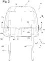
- the headrest 10 comprises according to FIG Fig. 1 and 2 a headrest part 11 and a holding device 12. With the holding device 12, the headrest part 11 can be mounted in a known manner on a vehicle seat, not shown here. It serves as an abutment for the head of the vehicle occupant and can transmit forces acting on a head contact surface 14 to the vehicle seat.
- the direction facing forwards in relation to an occupant whose head is to be supported by the headrest 10 is denoted by x1 and the opposite, rearward-facing direction is denoted by x2.
- the holding device comprises support rods 13a and 13b which are mounted in receptacles in the vehicle seat.
- the head support part 11 is mounted on the support rods 13a and 13b so as to be adjustable in the directions z1 and z2 relative to the support rods 13a and 13b.
- the headrest 10 has a locking device 17 (see FIG Fig. 2 ).
- the locking device 17 is an adjusting device within the meaning of the invention.
- the locking device 17 comprises first locking elements 41a and 41b (see FIG Fig. 2 ), of the headrest part 11 which interact with second locking elements 42a and 42b of the holding device 12 in order to releasably lock the headrest part 11.
- the first locking elements 41a and 41b have the shape of locking edges which are assigned to a slide 40.
- the locking edges are in one piece with the slide 40 shaped.
- the second locking elements 42a and 42b have the shape of recesses in each of the support rods 13a and 13b.
- the locking device 17 is movable between a locking position and a release position. In the locking position, the locking means are engaged and the head support part 11 is locked immovably in the directions z1 and z2 relative to the support rods 13a and 13b. According to an alternative, the head contact part 11 could be immovable in the direction z2 and movable in the direction z1 in the locking position despite the engagement of the locking elements. In the release position, the headrest part 11 can be moved in the directions z1 and z2. The locking device 17 is loaded into the locking position by a reset device.
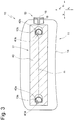
- the locking device 17 With an actuating device 15, which has a central axis m, the locking device 17 can be adjusted from the locking position into the release position in which the locking elements 41a, 41b, 42a and 42b are disengaged.
- the actuating device 15 comprises an actuating element 16. In the non-actuated position of the actuating device 15, the locking device 17 is in the locking position and in the actuated position of the actuating element 16 the locking device 17 is in the release position.
- the actuating device 15 comprises a spring 18 with which the actuating element 16 is loaded into the non-actuated position.
- the spring 18 is designed as a spiral spring.
- the actuating element 16 In the actuated position, the actuating element 16 is displaced in relation to the non-actuated position in the direction y1 due to the actuation of a user, and in the non-actuated position the actuating element 16 is due to shifted the restoring force of the spring 18 with respect to the actuated position in the direction y2.
- the slide is connected to the actuating device in such a way that when the actuating element 16 is moved from the non-actuated position to the actuated position with respect to a frame 19 of the actuating device 15, the head box of the headrest 10 is fixedly held on a head box of the headrest 10 that is immovable relative to the support rods 13a and 13b , the slide 40 is also moved in the direction y1, the locking elements 41a and 42a as well as 41b and 42b disengaging. If the actuating element 16 is relieved of pressure, the slide 40, which is loaded by a spring (not shown) in the direction y2, is again in the direction y2 in the position according to Fig. 3 moves with the locking members 41a and 42a and 41b and 42b moving into engagement. The actuating element 16 is moved into the non-actuated position by the spring 18.
- FIG. 13 shows a side view of the headrest 10, with the parts shown in FIG Fig. 3 are covered, are shown in dashed lines.
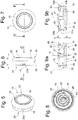
- the actuator 15 is in the Figures 5 to 9 shown as an assembly.
- the actuating device 15 comprises the frame 19, which in the present exemplary embodiment is designed as a sleeve which is essentially closed in the circumferential direction, which forms a collar at one end region 23 and is provided with openings at both end regions 23 and 24 with respect to the central axis m.
- the frame 19 could, however, also have a different shape, for example it could be formed as a frame from mere guide strips.
- the frame could alternatively also be formed on a fixed structure of the piece of equipment, such as, for example, on the head box of the headrest 10. In this case, it can be provided with the same features as the frame described in this exemplary embodiment.
- the frame 19 is provided with opposing fastening means 20a and 20b - here in the form of recesses - which will be explained below become.
- the frame 19 forms a shoulder 21 which serves as a stop for mounting on the head support part 13.
- the frame 19 forms an approximately circular cylindrical interior 22 in the present exemplary embodiment.
- the actuating element 16 is movably guided in the interior 22 of the frame 19 between the non-actuated position and the actuated position, see FIG Figures 9a and 9b .
- the actuating element 16 is arranged in an actuatable manner in the interior space 22.
- An actuation surface 35 of the actuation element 16 comprises an edge region 36 which is radially removed from the central axis m and a central region 37 which is arranged close to the central axis.
- the central area 37 is set back in relation to the edge area 36 in the direction y1. From the edge area 36, the actuating surface 35 gently merges into the central area 37, so that a trough is formed, which is advantageous for haptic reasons.
- the spring 18 is arranged on an end region 24 of the interior 22 opposite the end region 23. As in Fig. 7 can be seen, the actuating element 16 and the spring 18 are formed coaxially to the central axis m.
- the spring 18 extends spirally essentially within a plane E1 which runs approximately at right angles to the central axis m. According to Fig. 8 the spring comprises an outer end region 25 and an inner end region 26. The outer end region 25 is fastened to the frame 19 so that it can neither be rotated about the central axis nor moved in directions y1 and y2.
- the inner end region 26 is connected to the actuating element 16 by a connection 27 in the form of a web that is U-shaped in cross section to the central axis.
- the frame 19 has at least one abutment surface 28 inclined by approximately 45 degrees relative to the central axis m, which is designed to be complementary with at least one Contact surface 29 cooperates in such a way that it forms a stop for the actuating element 16 and centers it in the non-actuated position.
- the frame 19 is shown as a single part. It comprises the diametrically opposite fastening means 20a and 20b as well as four first guide means 30 extending parallel to the central axis m and distributed over the inner circumference of a surface 39 of the interior 22 in the form of grooves opposite one another with respect to the central axis m, of which only one is groove in Fig. 10 is recognizable.
- the actuation unit comprising actuation element 16, connection 27 and spring 18, is shown.
- the annular outer end region 25 has a radially directed flank surface 38, from which the fastening means 31a and 31b - each in the form of a projection - project diametrically opposite with respect to the central axis m.
- Each projection has an inclined surface 33 formed at an angle to the central axis m and a holding surface 34 formed approximately at right angles to the central axis m.
- the actuating element 16 extends within a plane E2 and comprises four guide means 32, which protrude radially outward with respect to the central axis m, which are distributed over the circumference and which slide together with the guide means 30 during the movement between the non-actuated position and the actuated position and guide the actuating element 16 .
- connection 27 extends in the directions y1 and y2 between the actuating element 16 and the spring 18.
- the connection 27 is U-shaped in cross section to the central axis m. From the connection, the spring 18 extends approximately at right angles to the central axis m in a plane E1 and the actuating element 16 extends approximately at right angles to the central axis m in a plane E2.
- the plane E2 is parallel to the plane E1.
- the spring 18, the connection 27 and the actuating element 16 form the actuating unit 43, which is manufactured in one piece using the plastic injection molding process.
- the spring 18, the connection 27 and the actuating element 16 can also be produced as an assembly of individual parts connected to one another.
- the actuating unit 43 is made, for example, of a plastic, in particular a glass fiber reinforced plastic.
- the plastic is e.g. polypropylene or polyamide or e.g. a polycarbonate / acrylonitrile-butadiene-styrene blend.
Applications Claiming Priority (1)
| Application Number | Priority Date | Filing Date | Title |
|---|---|---|---|
| DE102019006162.4A DE102019006162B4 (de) | 2019-09-02 | 2019-09-02 | Betätigungsvorrichtung zur Betätigung einer Ausstattungsvorrichtung des Fahrzeuginnenraums und ein Fahrzeugausstattungsteil |
Publications (1)
| Publication Number | Publication Date |
|---|---|
| EP3785985A1 true EP3785985A1 (fr) | 2021-03-03 |
Family
ID=71899580
Family Applications (1)
| Application Number | Title | Priority Date | Filing Date |
|---|---|---|---|
| EP20188903.7A Pending EP3785985A1 (fr) | 2019-09-02 | 2020-07-31 | Dispositif d'actionnement pour une partie d'équipement de véhicule et dispositif d'équipement doté d'un dispositif d'actionnement |
Country Status (4)
| Country | Link |
|---|---|
| US (1) | US11453321B2 (fr) |
| EP (1) | EP3785985A1 (fr) |
| CN (1) | CN112440847A (fr) |
| DE (1) | DE102019006162B4 (fr) |
Families Citing this family (1)
| Publication number | Priority date | Publication date | Assignee | Title |
|---|---|---|---|---|
| DE102022116985A1 (de) | 2022-07-07 | 2024-01-18 | Grammer Aktiengesellschaft | Verfahren und Vorrichtung zur Montage einer Kopfstütze für einen Fahrzeugsitz |
Citations (3)
| Publication number | Priority date | Publication date | Assignee | Title |
|---|---|---|---|---|
| DE202005007516U1 (de) * | 2005-05-12 | 2005-09-08 | Faurecia Autositze Gmbh & Co. Kg | Fahrzeugsitz mit einer Kopfstütze |
| US20140203615A1 (en) * | 2013-01-22 | 2014-07-24 | Windsor Machine & Stamping, Ltd | Head restraint assembly for a vehicle |
| DE102015011477A1 (de) | 2015-02-20 | 2016-08-25 | Grammer Ag | Kopfstütze |
Family Cites Families (12)
| Publication number | Priority date | Publication date | Assignee | Title |
|---|---|---|---|---|
| US4504091A (en) * | 1982-08-31 | 1985-03-12 | Shiroki Kinzoku Kogyo Kabushiki Kaisha | Reclining angle adjustment device |
| DE3621278A1 (de) * | 1986-06-25 | 1988-01-21 | Opel Adam Ag | Umlegbare kopfstuetze fuer einen fahrzeugsitz, insbesondere fuer einen ruecksitz eines personenwagens |
| CN2132872Y (zh) * | 1992-09-18 | 1993-05-12 | 陈谟有 | 盘形弹簧 |
| ES2072796T3 (es) * | 1992-10-14 | 1995-07-16 | Bruzolo Manifatt Gestind Mb | Apoyacabezas para asientos de vehiculos automoviles, particularmente para asientos posteriores. |
| JPH06323353A (ja) * | 1993-05-13 | 1994-11-25 | Iwao Kojima | 板から成る錐体形蔓巻バネ |
| JP2010031895A (ja) * | 2008-07-25 | 2010-02-12 | Saida Seiki Kogyo Kk | 押し引き両用ばね及びその製造方法 |
| DE202009016091U1 (de) | 2009-11-20 | 2010-03-11 | Austriamicrosystems Ag | Feder und Taster |
| DE102010054314B4 (de) | 2010-12-10 | 2020-12-17 | Adient Luxembourg Holding S.À R.L. | Beschlagsystem für einen Fahrzeugsitz |
| CN202096738U (zh) * | 2010-12-17 | 2012-01-04 | 刘锦 | 伸缩式玩具 |
| DE102017211720B4 (de) * | 2016-07-20 | 2022-06-30 | Lear Corporation | Sitzaufbau mit einem einstellbaren Kopfstützenaufbau |
| US11021238B2 (en) * | 2017-02-07 | 2021-06-01 | Parker-Hannifin Corporation | Disc spring providing linear axial motion |
| US11117504B2 (en) * | 2017-06-29 | 2021-09-14 | Tesca France | Headrest for a motor vehicle seat |
-
2019
- 2019-09-02 DE DE102019006162.4A patent/DE102019006162B4/de active Active
-
2020
- 2020-07-31 US US16/945,025 patent/US11453321B2/en active Active
- 2020-07-31 EP EP20188903.7A patent/EP3785985A1/fr active Pending
- 2020-09-01 CN CN202010901245.7A patent/CN112440847A/zh active Pending
Patent Citations (3)
| Publication number | Priority date | Publication date | Assignee | Title |
|---|---|---|---|---|
| DE202005007516U1 (de) * | 2005-05-12 | 2005-09-08 | Faurecia Autositze Gmbh & Co. Kg | Fahrzeugsitz mit einer Kopfstütze |
| US20140203615A1 (en) * | 2013-01-22 | 2014-07-24 | Windsor Machine & Stamping, Ltd | Head restraint assembly for a vehicle |
| DE102015011477A1 (de) | 2015-02-20 | 2016-08-25 | Grammer Ag | Kopfstütze |
Also Published As
| Publication number | Publication date |
|---|---|
| DE102019006162A1 (de) | 2021-03-04 |
| CN112440847A (zh) | 2021-03-05 |
| US11453321B2 (en) | 2022-09-27 |
| DE102019006162B4 (de) | 2021-11-18 |
| US20210061151A1 (en) | 2021-03-04 |
Similar Documents
| Publication | Publication Date | Title |
|---|---|---|
| DE102015011477B4 (de) | Kopfstütze | |
| EP3113986B1 (fr) | Tenon d'enclenchement servant à fixer un module de coussin à gaz sur un véhicule automobile | |
| EP3045347A1 (fr) | Dispositif de stockage et appui-tete | |
| EP3228493B1 (fr) | Accoudoir | |
| DE102013107728A1 (de) | Klemmvorrichtung für eine längsverstellbare und/oder höhenverstellbare Lenksäule eines Fahrzeugs | |
| EP0641532B1 (fr) | Colonne ajustable en longueur pour chaises, tables ou similaires | |
| DE102016014039A1 (de) | Kopfstütze, Verfahren zur Montage einer Kopfstütze und Kopfstützensystem | |
| WO2017021519A1 (fr) | Unité de volant de direction | |
| EP3785985A1 (fr) | Dispositif d'actionnement pour une partie d'équipement de véhicule et dispositif d'équipement doté d'un dispositif d'actionnement | |
| DE102006015757A1 (de) | Becherhalter für ein Kraftfahrzeug | |
| EP3287314B1 (fr) | Siège de vehicule avec dispositif | |
| DE102005032887B3 (de) | Verfahren zur Herstellung einer Lageranordnung und Lageranordnung | |
| DE19806790B4 (de) | Vorrichtung an einem Betätigungsorgan, insbesondere einer Türgriffanordnung an einem Kraftfahrzeug | |
| DE102007031436A1 (de) | Armlehne für einen Fahrzeugsitz | |
| EP3656609A1 (fr) | Pièce d'équipement de véhicule | |
| EP3059117B1 (fr) | Appuie-tete | |
| EP3406482B1 (fr) | Appuie-tête et procédé de montage d'un appuie-tête | |
| EP3048005A1 (fr) | Dossier d'un siege de vehicule comprenant un appuie-tete | |
| WO2018166547A1 (fr) | Écrou pour une vis à billes et procédé de fabrication d'un écrou | |
| DE4337145A1 (de) | Ausstattungsteil für Kraftfahrzeuge | |
| DE10151360B4 (de) | Vorrichtung zur Aufnahme von Kopfstützenbügeln | |
| DE102015110594A1 (de) | Armauflage für ein Fahrzeuginnenausstattungsteil | |
| DE102016115267B4 (de) | Vorrichtung zum Einstellen einer Rückenlehnenneigung und Verfahren zur Montage der Vorrichtung | |
| DE102019105696A1 (de) | Klemmvorrichtung für eine Lenksäule sowie Verstellvorrichtung für eine Lenksäule | |
| DE202005013054U1 (de) | Sicherheitseinheit für eine Verstelleinrichtung für Lenksäulen von Fahrzeugen, vorzugsweise von Kraftfahrzeugen |
Legal Events
| Date | Code | Title | Description |
|---|---|---|---|
| PUAI | Public reference made under article 153(3) epc to a published international application that has entered the european phase |
Free format text: ORIGINAL CODE: 0009012 |
|
| STAA | Information on the status of an ep patent application or granted ep patent |
Free format text: STATUS: THE APPLICATION HAS BEEN PUBLISHED |
|
| AK | Designated contracting states |
Kind code of ref document: A1 Designated state(s): AL AT BE BG CH CY CZ DE DK EE ES FI FR GB GR HR HU IE IS IT LI LT LU LV MC MK MT NL NO PL PT RO RS SE SI SK SM TR |
|
| AX | Request for extension of the european patent |
Extension state: BA ME |
|
| STAA | Information on the status of an ep patent application or granted ep patent |
Free format text: STATUS: REQUEST FOR EXAMINATION WAS MADE |
|
| 17P | Request for examination filed |
Effective date: 20210820 |
|
| RBV | Designated contracting states (corrected) |
Designated state(s): AL AT BE BG CH CY CZ DE DK EE ES FI FR GB GR HR HU IE IS IT LI LT LU LV MC MK MT NL NO PL PT RO RS SE SI SK SM TR |
|
| STAA | Information on the status of an ep patent application or granted ep patent |
Free format text: STATUS: EXAMINATION IS IN PROGRESS |
|
| 17Q | First examination report despatched |
Effective date: 20230112 |