EP3785985A1 - Actuating device for a vehicle equipment part and equipment device with an actuating device - Google Patents
Actuating device for a vehicle equipment part and equipment device with an actuating device Download PDFInfo
- Publication number
- EP3785985A1 EP3785985A1 EP20188903.7A EP20188903A EP3785985A1 EP 3785985 A1 EP3785985 A1 EP 3785985A1 EP 20188903 A EP20188903 A EP 20188903A EP 3785985 A1 EP3785985 A1 EP 3785985A1
- Authority
- EP
- European Patent Office
- Prior art keywords
- actuating
- actuating element
- frame
- actuating device
- end region
- Prior art date
- Legal status (The legal status is an assumption and is not a legal conclusion. Google has not performed a legal analysis and makes no representation as to the accuracy of the status listed.)
- Pending
Links
Images


Classifications
-
- B—PERFORMING OPERATIONS; TRANSPORTING
- B60—VEHICLES IN GENERAL
- B60N—SEATS SPECIALLY ADAPTED FOR VEHICLES; VEHICLE PASSENGER ACCOMMODATION NOT OTHERWISE PROVIDED FOR
- B60N2/00—Seats specially adapted for vehicles; Arrangement or mounting of seats in vehicles
- B60N2/80—Head-rests
- B60N2/806—Head-rests movable or adjustable
- B60N2/809—Head-rests movable or adjustable vertically slidable
- B60N2/812—Head-rests movable or adjustable vertically slidable characterised by their locking devices
- B60N2/815—Release mechanisms, e.g. buttons
-
- B—PERFORMING OPERATIONS; TRANSPORTING
- B60—VEHICLES IN GENERAL
- B60N—SEATS SPECIALLY ADAPTED FOR VEHICLES; VEHICLE PASSENGER ACCOMMODATION NOT OTHERWISE PROVIDED FOR
- B60N2/00—Seats specially adapted for vehicles; Arrangement or mounting of seats in vehicles
- B60N2/80—Head-rests
- B60N2/806—Head-rests movable or adjustable
- B60N2/809—Head-rests movable or adjustable vertically slidable
- B60N2/829—Head-rests movable or adjustable vertically slidable characterised by their adjusting mechanisms, e.g. electric motors
-
- B—PERFORMING OPERATIONS; TRANSPORTING
- B60—VEHICLES IN GENERAL
- B60N—SEATS SPECIALLY ADAPTED FOR VEHICLES; VEHICLE PASSENGER ACCOMMODATION NOT OTHERWISE PROVIDED FOR
- B60N2/00—Seats specially adapted for vehicles; Arrangement or mounting of seats in vehicles
- B60N2/80—Head-rests
- B60N2/806—Head-rests movable or adjustable
-
- B—PERFORMING OPERATIONS; TRANSPORTING
- B60—VEHICLES IN GENERAL
- B60N—SEATS SPECIALLY ADAPTED FOR VEHICLES; VEHICLE PASSENGER ACCOMMODATION NOT OTHERWISE PROVIDED FOR
- B60N2/00—Seats specially adapted for vehicles; Arrangement or mounting of seats in vehicles
- B60N2/02—Seats specially adapted for vehicles; Arrangement or mounting of seats in vehicles the seat or part thereof being movable, e.g. adjustable
-
- B—PERFORMING OPERATIONS; TRANSPORTING
- B60—VEHICLES IN GENERAL
- B60N—SEATS SPECIALLY ADAPTED FOR VEHICLES; VEHICLE PASSENGER ACCOMMODATION NOT OTHERWISE PROVIDED FOR
- B60N2/00—Seats specially adapted for vehicles; Arrangement or mounting of seats in vehicles
- B60N2/75—Arm-rests
- B60N2/763—Arm-rests adjustable
-
- B—PERFORMING OPERATIONS; TRANSPORTING
- B60—VEHICLES IN GENERAL
- B60N—SEATS SPECIALLY ADAPTED FOR VEHICLES; VEHICLE PASSENGER ACCOMMODATION NOT OTHERWISE PROVIDED FOR
- B60N2/00—Seats specially adapted for vehicles; Arrangement or mounting of seats in vehicles
- B60N2/80—Head-rests
- B60N2/806—Head-rests movable or adjustable
- B60N2/809—Head-rests movable or adjustable vertically slidable
- B60N2/812—Head-rests movable or adjustable vertically slidable characterised by their locking devices
-
- B—PERFORMING OPERATIONS; TRANSPORTING
- B60—VEHICLES IN GENERAL
- B60N—SEATS SPECIALLY ADAPTED FOR VEHICLES; VEHICLE PASSENGER ACCOMMODATION NOT OTHERWISE PROVIDED FOR
- B60N2/00—Seats specially adapted for vehicles; Arrangement or mounting of seats in vehicles
- B60N2/80—Head-rests
- B60N2/806—Head-rests movable or adjustable
- B60N2/809—Head-rests movable or adjustable vertically slidable
- B60N2/832—Head-rests movable or adjustable vertically slidable movable to an inoperative or stowed position
-
- B—PERFORMING OPERATIONS; TRANSPORTING
- B60—VEHICLES IN GENERAL
- B60N—SEATS SPECIALLY ADAPTED FOR VEHICLES; VEHICLE PASSENGER ACCOMMODATION NOT OTHERWISE PROVIDED FOR
- B60N2/00—Seats specially adapted for vehicles; Arrangement or mounting of seats in vehicles
- B60N2/80—Head-rests
- B60N2/806—Head-rests movable or adjustable
- B60N2/838—Tiltable
- B60N2/841—Tiltable characterised by their locking devices
- B60N2/844—Release mechanisms, e.g. buttons
Definitions
- the invention relates to an actuating device for an equipment device of a vehicle.
- a vehicle is a land, air or water vehicle.
- the equipment device for example a headrest or an armrest of a vehicle seat, comprises an adjustment device which is adjustable between a first position and a second position in order to set, switch or control certain vehicle functions.
- the adjustment device is adjusted using an actuation device which comprises an actuation element that can be displaced between an inactivated position and an actuated position.
- the actuating element is loaded into the non-actuated position by a restoring device in the form of a coil spring made of metal, which is formed coaxially to a central axis of the adjustment directions.
- the actuating device comprises an actuating element which is movable relative to a frame between an inoperative position and an actuated position.
- the actuating element is, for example, a button.
- the actuator is suitable for this directly or indirectly with a Adjusting device of an equipment device of a vehicle interior to be brought into connection, so that a function of the equipment device can be switched or controlled or adjusted with the actuating device when the actuating device is moved between the non-actuated position and the actuated position. For example, at least part of the adjusting device can be moved.
- the actuating element moves, for example, in a straight line axially between the non-actuated and the actuated position.
- the actuating element can, for example, be movable axially along the central axis of the actuating device. Parts can be interposed between the actuating element and the equipment device which are movement-connected to the actuating element but perform a different movement and / or a movement in other directions.
- the actuating device comprises a restoring device with at least one spring for reloading the actuating device into the non-actuated position. This means that the actuating element automatically moves back into the non-actuated position after relieving the load.
- At least one spring of the return device is designed as a spiral spring and is wound in a spiral around a central axis.
- the central axis is e.g. parallel to the adjustment directions of the actuating element.
- the spring has an outer end region arranged at a distance from the central axis and an inner end region arranged closer to the central axis with respect to the first end region.
- the spring is deflected by a relative movement of the inner end area relative to the outer end area in the adjustment direction parallel to the central axis of the spring.
- the spring extends in a plane substantially perpendicular to the central axis.
- the actuating device has the advantage that it can be manufactured as a plastic injection-molded part.
- the device is lightweight and takes up a small amount of space.
- the actuating device can be manufactured as an assembly with a few parts or in one piece.
- the actuating element is connected to the inner end area or to the outer end area and the respective other end area is connected to the equipment device, for example a housing of the equipment device.
- the actuating element is connected to the inner end area and the outer end area is held directly or indirectly on the equipment device.
- the actuating element is connected to the outer end area and the inner end area is held on the equipment device. One end area is thus firmly held on the equipment device and the other end area can be deflected relative to the one end area by means of the actuating element.
- the deflected end region of the spring or a region of the actuating element can be connected to at least one part of the equipment device in such a way that it is moved between a first position and a second position when the actuating device is moved between the non-actuated position and the actuated position.
- the actuating device comprises a frame which is designed for attachment to the equipment device, the actuating element being movable relative to the frame during the movement between the non-actuated position and the actuated position.
- the actuating device can be completely preassembled and attached as an assembly to the equipment device and connected to at least one other part of the equipment device.
- the frame comprises, for example, first guide means and the actuating element second guide means which cooperate during the movement of the actuating element between the non-actuated position and the actuated position in order to guide the movement of the actuating element.
- One guide means are formed, for example, by grooves and the other guide means are formed by projections which slide in the grooves and thereby move the actuating element between the non-actuated position and the actuated position on the frame to lead. In this way, the actuating element is guided during the movement and does not tilt.
- the outer end region of the spiral spring forms, for example, a ring which can be fastened to the frame. It is advantageous if the ring has the same cross-sectional shape in relation to the central axis as the frame.
- the frame and the outer end region are complementary in cross-section in the form of a circular ring or form a rectangular ring. Then the spring can be stored in an interior of the frame. Alternatively, however, the end region can also have a different cross-sectional shape.
- the frame comprises, for example, fastening means which are engageable with counter-fastening means of the ring of the coil spring.
- one fastening means can be formed by projections and the other fastening means by recesses.
- the projections are provided, for example, with assembly bevels which favor elastic deformation of the projections arranged with excess relative to the frame on the outer spring end, so that they snap into the recesses when the positions of the projections and those of the recesses coincide.
- the actuating element is, if not directly, connected indirectly by means of a connection to the first end region or to the second end region of the spring.
- a distance between the location of the spring and the location of the actuating element in the non-actuated position can be bridged in this way and a movement connection can be created.
- the connection can be formed by a web.
- the web can, for example, be U-shaped, which gives it a high level of stability.
- the frame is, for example, sleeve-shaped. It can, for example, be approximately cylindrical, for example circular cylindrical. It can, for example, have a wall forming the jacket surface and openings at opposite exit points of a longitudinal center axis of the sleeve.
- the actuating element can be actuated through one of the openings and through the other opening an actuation of the adjustment device of the equipment device can be made.
- the frame is, for example, designed to be essentially closed on the circumference. If the frame is, for example, designed in the form of a sleeve, the lateral surface can, for example, be designed to be essentially closed. In this way it is prevented that the function of the actuating device is impaired by dirt.
- the frame forms, for example, a stop surface which interacts with a contact surface of the actuating element in order to limit the movement of the actuating element in an adjustment direction.
- the contact surface of the actuating element can be loaded by the other spring end against the stop surface. This can, for example, also prevent the development of noise due to vibration or rattling of the actuating element.
- the stop surface and the contact surface are for example inclined, in particular at a 45 degree angle, in order to center the button on the frame. Since the actuating element must be supported in the frame with play, in the non-actuated position of the actuating element there could be different positions or a relative movement between the actuating element and the frame in the radial direction to the central axis. By means of the incline, the actuating element is centered on the frame in the non-actuated position, i.e. it has a defined position. This avoids noise and gives the user a higher quality impression.
- the spiral spring is provided with a preload, for example in the non-actuated position.
- This embodiment ensures that there cannot be a relative movement between the actuating element and the frame in the non-actuated position in a direction parallel to the central axis. Due to the preload, the contact surface of the spring with the Pre-tensioning force pressed against the stop surface. Rattling noises are avoided in this way.
- the actuating element is, for example, formed in one piece with the spiral spring.
- the actuating element, the spiral spring and, if applicable, the connection can be easily produced and assembled if they are made in one piece.
- the actuating element, spiral spring and possibly the connection are molded in one piece from a plastic in an injection molding process. This ensures simple production and low weight.
- the actuating device is formed, for example, from a plastic.
- the frame and the spiral spring, the actuating element and possibly the connection can be made of plastic, with the advantage of simple manufacture and low weight.
- the invention relates to an equipment device for a vehicle.
- Such an equipment device can be, for example, a headrest or an armrest.
- a headrest is for example from the DE 10 2015 011 477 A1 known to the applicant.
- the equipment device comprises an adjustment device which comprises at least one movable part.
- the adjustment device can be adjusted between a first position and a second position.
- the equipment device further comprises an actuating device for actuating the adjusting device.
- the actuating device is moved from the non-actuated position into the actuated position, the adjusting device is adjusted from the first position into the second position.
- the movement of the adjusting device into the second position takes place through a movement connection between the actuating device and the adjusting device.
- the adjusting device When the actuating device is moved from the actuated position to the non-actuated position, the adjusting device is moved, for example, from the second position to the first position.
- This movement of the adjusting device into the first position can take place through a movement connection between the actuating device and the adjusting device or through a separate restoring element of the adjusting device, which was tensioned during the movement into the second position.
- the actuating device is designed according to the first aspect of the invention. In order to avoid repetition, the properties and advantages of the actuating device will not be discussed again here.
- the equipment device can be a headrest for vehicle seats.
- the headrest is intended as an abutment for the head of the vehicle occupant.
- the headrest comprises a headrest part which can be mounted on the vehicle seat by means of a holding device for the headrest.
- the holding device can, for example, have two individual support rods or one support rod bracket.
- the holding device can also be designed differently, for example.
- the headrest part is not vertically adjustable relative to the vehicle seat.
- the holding device can be designed differently for such a headrest.
- the headrest part is, for example, adjustable vertically and / or horizontally and / or with respect to its inclination relative to the vehicle seat, in particular relative to the backrest of the vehicle seat.
- the adjusting device comprises guides which ensure adjustability.
- the headrest comprises an adjustment device which is adjustable between a first position and a second position.
- the adjusting device can, for example, interact with a locking device or be part of this locking device.
- the locking device is movable between a locking position and a release position.
- an actuation device that comprises an actuation element, the locking device can be moved by the user from outside on the headrest between the locking position and the release position. In an unactuated position of the actuating device, the locking device is in the locking position and in an actuated position of the actuating device, the locking device is in the release position.
- the locking device is designed, for example, to lock the vertical position and / or the horizontal position and / or the inclined position of the head rest part.
- the actuating element is loaded into the non-actuated position by a spring.
- the locking device comprises first locking means, which are assigned to the headrest part and second locking means, which are assigned to the holding device or a base part of the headrest, to which the headrest part can be moved relative to. In the latter case, the base part of the headrest is mounted on the holding device and the headrest part is mounted on the base part.
- the actuating device of the headrest is designed, for example, in this embodiment of the piece of equipment according to the first aspect of the invention.
- a headrest as a whole is denoted by the reference numeral 10 in the figures.
- the headrest is an equipment device within the meaning of the invention.
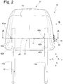
- the headrest 10 comprises according to FIG Fig. 1 and 2 a headrest part 11 and a holding device 12. With the holding device 12, the headrest part 11 can be mounted in a known manner on a vehicle seat, not shown here. It serves as an abutment for the head of the vehicle occupant and can transmit forces acting on a head contact surface 14 to the vehicle seat.
- the direction facing forwards in relation to an occupant whose head is to be supported by the headrest 10 is denoted by x1 and the opposite, rearward-facing direction is denoted by x2.
- the holding device comprises support rods 13a and 13b which are mounted in receptacles in the vehicle seat.
- the head support part 11 is mounted on the support rods 13a and 13b so as to be adjustable in the directions z1 and z2 relative to the support rods 13a and 13b.
- the headrest 10 has a locking device 17 (see FIG Fig. 2 ).
- the locking device 17 is an adjusting device within the meaning of the invention.
- the locking device 17 comprises first locking elements 41a and 41b (see FIG Fig. 2 ), of the headrest part 11 which interact with second locking elements 42a and 42b of the holding device 12 in order to releasably lock the headrest part 11.
- the first locking elements 41a and 41b have the shape of locking edges which are assigned to a slide 40.
- the locking edges are in one piece with the slide 40 shaped.
- the second locking elements 42a and 42b have the shape of recesses in each of the support rods 13a and 13b.
- the locking device 17 is movable between a locking position and a release position. In the locking position, the locking means are engaged and the head support part 11 is locked immovably in the directions z1 and z2 relative to the support rods 13a and 13b. According to an alternative, the head contact part 11 could be immovable in the direction z2 and movable in the direction z1 in the locking position despite the engagement of the locking elements. In the release position, the headrest part 11 can be moved in the directions z1 and z2. The locking device 17 is loaded into the locking position by a reset device.
- the locking device 17 With an actuating device 15, which has a central axis m, the locking device 17 can be adjusted from the locking position into the release position in which the locking elements 41a, 41b, 42a and 42b are disengaged.
- the actuating device 15 comprises an actuating element 16. In the non-actuated position of the actuating device 15, the locking device 17 is in the locking position and in the actuated position of the actuating element 16 the locking device 17 is in the release position.
- the actuating device 15 comprises a spring 18 with which the actuating element 16 is loaded into the non-actuated position.
- the spring 18 is designed as a spiral spring.
- the actuating element 16 In the actuated position, the actuating element 16 is displaced in relation to the non-actuated position in the direction y1 due to the actuation of a user, and in the non-actuated position the actuating element 16 is due to shifted the restoring force of the spring 18 with respect to the actuated position in the direction y2.
- the slide is connected to the actuating device in such a way that when the actuating element 16 is moved from the non-actuated position to the actuated position with respect to a frame 19 of the actuating device 15, the head box of the headrest 10 is fixedly held on a head box of the headrest 10 that is immovable relative to the support rods 13a and 13b , the slide 40 is also moved in the direction y1, the locking elements 41a and 42a as well as 41b and 42b disengaging. If the actuating element 16 is relieved of pressure, the slide 40, which is loaded by a spring (not shown) in the direction y2, is again in the direction y2 in the position according to Fig. 3 moves with the locking members 41a and 42a and 41b and 42b moving into engagement. The actuating element 16 is moved into the non-actuated position by the spring 18.
- FIG. 13 shows a side view of the headrest 10, with the parts shown in FIG Fig. 3 are covered, are shown in dashed lines.
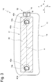
- the actuator 15 is in the Figures 5 to 9 shown as an assembly.
- the actuating device 15 comprises the frame 19, which in the present exemplary embodiment is designed as a sleeve which is essentially closed in the circumferential direction, which forms a collar at one end region 23 and is provided with openings at both end regions 23 and 24 with respect to the central axis m.
- the frame 19 could, however, also have a different shape, for example it could be formed as a frame from mere guide strips.
- the frame could alternatively also be formed on a fixed structure of the piece of equipment, such as, for example, on the head box of the headrest 10. In this case, it can be provided with the same features as the frame described in this exemplary embodiment.
- the frame 19 is provided with opposing fastening means 20a and 20b - here in the form of recesses - which will be explained below become.
- the frame 19 forms a shoulder 21 which serves as a stop for mounting on the head support part 13.
- the frame 19 forms an approximately circular cylindrical interior 22 in the present exemplary embodiment.
- the actuating element 16 is movably guided in the interior 22 of the frame 19 between the non-actuated position and the actuated position, see FIG Figures 9a and 9b .
- the actuating element 16 is arranged in an actuatable manner in the interior space 22.
- An actuation surface 35 of the actuation element 16 comprises an edge region 36 which is radially removed from the central axis m and a central region 37 which is arranged close to the central axis.
- the central area 37 is set back in relation to the edge area 36 in the direction y1. From the edge area 36, the actuating surface 35 gently merges into the central area 37, so that a trough is formed, which is advantageous for haptic reasons.
- the spring 18 is arranged on an end region 24 of the interior 22 opposite the end region 23. As in Fig. 7 can be seen, the actuating element 16 and the spring 18 are formed coaxially to the central axis m.
- the spring 18 extends spirally essentially within a plane E1 which runs approximately at right angles to the central axis m. According to Fig. 8 the spring comprises an outer end region 25 and an inner end region 26. The outer end region 25 is fastened to the frame 19 so that it can neither be rotated about the central axis nor moved in directions y1 and y2.
- the inner end region 26 is connected to the actuating element 16 by a connection 27 in the form of a web that is U-shaped in cross section to the central axis.
- the frame 19 has at least one abutment surface 28 inclined by approximately 45 degrees relative to the central axis m, which is designed to be complementary with at least one Contact surface 29 cooperates in such a way that it forms a stop for the actuating element 16 and centers it in the non-actuated position.
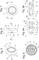
- the frame 19 is shown as a single part. It comprises the diametrically opposite fastening means 20a and 20b as well as four first guide means 30 extending parallel to the central axis m and distributed over the inner circumference of a surface 39 of the interior 22 in the form of grooves opposite one another with respect to the central axis m, of which only one is groove in Fig. 10 is recognizable.
- the actuation unit comprising actuation element 16, connection 27 and spring 18, is shown.
- the annular outer end region 25 has a radially directed flank surface 38, from which the fastening means 31a and 31b - each in the form of a projection - project diametrically opposite with respect to the central axis m.
- Each projection has an inclined surface 33 formed at an angle to the central axis m and a holding surface 34 formed approximately at right angles to the central axis m.
- the actuating element 16 extends within a plane E2 and comprises four guide means 32, which protrude radially outward with respect to the central axis m, which are distributed over the circumference and which slide together with the guide means 30 during the movement between the non-actuated position and the actuated position and guide the actuating element 16 .
- connection 27 extends in the directions y1 and y2 between the actuating element 16 and the spring 18.
- the connection 27 is U-shaped in cross section to the central axis m. From the connection, the spring 18 extends approximately at right angles to the central axis m in a plane E1 and the actuating element 16 extends approximately at right angles to the central axis m in a plane E2.
- the plane E2 is parallel to the plane E1.
- the spring 18, the connection 27 and the actuating element 16 form the actuating unit 43, which is manufactured in one piece using the plastic injection molding process.
- the spring 18, the connection 27 and the actuating element 16 can also be produced as an assembly of individual parts connected to one another.
- the actuating unit 43 is made, for example, of a plastic, in particular a glass fiber reinforced plastic.
- the plastic is e.g. polypropylene or polyamide or e.g. a polycarbonate / acrylonitrile-butadiene-styrene blend.
Abstract
Die Erfindung betrifft unter anderem eine Betätigungsvorrichtung (15) zur Betätigung einer Ausstattungsvorrichtung des Fahrzeuginnenraums, mit einem Betätigungselement, welches relativ zu einem Gehäuse zwischen einer unbetätigten Position und einer betätigten Position in entgegengesetzte Verstellrichtungen (y1, y2) bewegbar ist und mittels einer Rückstellvorrichtung in die unbetätigte Position belastet ist, wobei mit dem Betätigungselement ein mit dem Betätigungselement zusammenwirkendes Element der Ausstattungsvorrichtung verlagerbar ist.Die Besonderheit besteht darin, dass die Rückstellvorrichtung wenigstens eine als Spiralfeder ausgebildete Feder (18) mit einem äußeren Endbereich (25) und einem inneren Endbereich (26) umfasst.The invention relates, among other things, to an actuating device (15) for actuating an equipment device of the vehicle interior, with an actuating element which can be moved in opposite directions of adjustment (y1, y2) relative to a housing between an inoperative position and an actuated position and in the In the non-actuated position, an element of the equipment device that interacts with the actuation element can be displaced with the actuation element. The special feature is that the return device has at least one spring (18) designed as a spiral spring with an outer end region (25) and an inner end region (26 ) includes.
Description
Die Erfindung betrifft gemäß einem ersten Aspekt eine Betätigungsvorrichtung für eine Ausstattungsvorrichtung eines Fahrzeugs. Mit Fahrzeug ist im Sinne der Erfindung ein Land-, Luft- oder Wasserfahrzeug gemeint.According to a first aspect, the invention relates to an actuating device for an equipment device of a vehicle. In the context of the invention, a vehicle is a land, air or water vehicle.
Eine solche Betätigungsvorrichtung ist aus offenkundiger Vorbenutzung bekannt. Die Ausstattungsvorrichtung, z.B. eine Kopfstütze oder eine Armlehne eines Fahrzeugsitzes, umfasst eine Verstellvorrichtung, die zwischen einer ersten Position und einer zweiten Position verstellbar ist, um bestimmte Fahzeugfunktionen einzustellen, zu schalten oder zu steuern. Die Verstellung der Verstellvorrichtung erfolgt mit einer Betätigungsvorrichtung, die ein zwischen einer unbetätigten Position und einer betätigten Position verlagerbares Betätigungselement umfasst.Such an actuating device is known from prior public use. The equipment device, for example a headrest or an armrest of a vehicle seat, comprises an adjustment device which is adjustable between a first position and a second position in order to set, switch or control certain vehicle functions. The adjustment device is adjusted using an actuation device which comprises an actuation element that can be displaced between an inactivated position and an actuated position.
Das Betätigungselement wird im Stand der Technik von einer Rückstellvorrichtung in Form einer Schraubenfeder aus Metall, die koaxial zu einer Mittelachse der Verstellrichtungen ausgebildet ist, in die unbetätigte Position belastet.In the prior art, the actuating element is loaded into the non-actuated position by a restoring device in the form of a coil spring made of metal, which is formed coaxially to a central axis of the adjustment directions.
Es war Aufgabe der Erfindung, eine Betätigunsvorrichtung zu schaffen, die vorteilhaft herstellbar ist, wenig Bauraum einnimmt und ein geringes Gewicht aufweist.It was the object of the invention to create an actuating device which can be advantageously manufactured, takes up little installation space and is light in weight.
Die Aufgabe wurde gelöst mit einer Betätigungsvorrichtung gemäß den Merkmalen des Anspruchs 1.The object was achieved with an actuating device according to the features of claim 1.
Die Betätigungsvorrichtung umfasst ein Betätigungselement, welches relativ zu einem Rahmen zwischen einer unbetätigten Position und einer betätigten Position bewegbar ist. Das Betätigungselement ist z.B. eine Taste. Das Betätigungselement ist dafür geeignet unmittelbar oder mittelbar mit einer Verstellvorrichtung einer Ausstattungsvorrichtung eines Fahrzeuginnenraums in Verbindung gebracht zu werden, so dass mit der Betätigungsvorrichtung eine Funktion der Ausstattungsvorrichtung geschaltet oder gesteuert oder eingestellt werden kann, wenn die Betätigungsvorrichtung zwischen der unbetätigten Position und der betätigten Position bewegt wird. Z.B. kann wenigstens ein Teil der Verstellvorrichtung bewegt werden. Das Betätigungselement bewegt sich z.B. geradlinig axial zwischen der unbetätigten und der betätigten Position. Das Betätigungselement kann z.B. axial entlang der Mittelachse der Betätigungsvorrichtung bewegbar sein. Zwischen dem Betätigungselement und der Ausstattungsvorrichtung können Teile zwischengeschaltet sein, die mit dem Betätigungselement bewegungsverbunden sind aber eine andere Bewegung und / oder eine Bewegung in andere Richtungen durchführen.The actuating device comprises an actuating element which is movable relative to a frame between an inoperative position and an actuated position. The actuating element is, for example, a button. The actuator is suitable for this directly or indirectly with a Adjusting device of an equipment device of a vehicle interior to be brought into connection, so that a function of the equipment device can be switched or controlled or adjusted with the actuating device when the actuating device is moved between the non-actuated position and the actuated position. For example, at least part of the adjusting device can be moved. The actuating element moves, for example, in a straight line axially between the non-actuated and the actuated position. The actuating element can, for example, be movable axially along the central axis of the actuating device. Parts can be interposed between the actuating element and the equipment device which are movement-connected to the actuating element but perform a different movement and / or a movement in other directions.
Die Betätigungsvorrichtung umfasst eine Rückstellvorrichtung mit wenigstens einer Feder, zur Rückbelastung der Betätigungsvorrichtung in die unbetätigte Position. D.h., dass sich das Betätigungselement nach Entlastung z.B. automatisch in die unbetätigte Position zurückbewegt.The actuating device comprises a restoring device with at least one spring for reloading the actuating device into the non-actuated position. This means that the actuating element automatically moves back into the non-actuated position after relieving the load.
Wenigstens eine Feder der Rückstellvorrichtung ist als Spiralfeder ausgebildet und ist spiralförmig um eine Mittelachse gewunden. Die Mittelachse ist z.B. parallel zu den Verstellrichtungen des Betätigungselements angeodnet. Die Feder weist einen von der Mittelachse entfernt angeordneten äußeren Endbereich und einen bezüglich dem ersten Endbereich näher zu der Mittelachse angeordneten inneren Endbereich auf. Die Federauslenkung erfolgt durch eine Relativbewegung des inneren Endbereichs relativ zu dem äußeren Endbereich in Verstellrichtung parallel zu der Mittelachse der Feder. Die Feder erstreckt sich z.B. in einer Ebene, die im Wesentlichen rechtwinklig zu der Mittelachse ist.At least one spring of the return device is designed as a spiral spring and is wound in a spiral around a central axis. The central axis is e.g. parallel to the adjustment directions of the actuating element. The spring has an outer end region arranged at a distance from the central axis and an inner end region arranged closer to the central axis with respect to the first end region. The spring is deflected by a relative movement of the inner end area relative to the outer end area in the adjustment direction parallel to the central axis of the spring. For example, the spring extends in a plane substantially perpendicular to the central axis.
Die Betätigungsvorrichtung weist den Vorteil auf, dass sie als Kunststoffspritzgießteil herstellbar ist. Die Vorrichtung verursacht ein geringes Gewicht und nimmt einen kleinen Bauraum in Anspruch. Die Betätigungsvorrichtung kann als Baugruppe mit wenigen Teilen oder einteilig hergestellt sein.The actuating device has the advantage that it can be manufactured as a plastic injection-molded part. The device is lightweight and takes up a small amount of space. The actuating device can be manufactured as an assembly with a few parts or in one piece.
Gemäß einer Ausgestaltung der Erfindung ist das Betätigungselement mit dem inneren Endbereich oder mit dem äußeren Endbereich verbunden und der jeweils andere Endbereich ist mit der Ausstattungsvorrichtung, z.B. einem Gehäuse der Ausstattungsvorrichtung, verbunden. Z.B. ist das Betätigungselement mit dem inneren Endbereich verbunden und der äußere Endbereich ist an der Ausstattungsvorrichtung unmittelbar oder mittelbar gehalten. Gemäß einer Alternative ist das Betätigungselement mit dem äußeren Endbereich verbunden und der innere Endbereich ist an der Ausstattungsvorrichtung gehalten. Ein Endbereich ist somit fest an der Ausstattungsvorrichtung gehalten und mittels dem Betätigungselement kann der andere Endbereich relativ zu dem einen Endbereich ausgelenkt werden. Der ausgelenkte Endbereich der Feder oder ein Bereich des Betätigungselements ist derart mit wenigstens einem Teil der Ausstattungsvorrichtung verbindbar, dass dieses zwischen einer ersten Position und einer zweiten Position bewegt wird, wenn die Betätigungsvorrichtung zwischen der unbetätigten Position und der betätigten Position bewegt wird.According to one embodiment of the invention, the actuating element is connected to the inner end area or to the outer end area and the respective other end area is connected to the equipment device, for example a housing of the equipment device. For example, the actuating element is connected to the inner end area and the outer end area is held directly or indirectly on the equipment device. According to an alternative, the actuating element is connected to the outer end area and the inner end area is held on the equipment device. One end area is thus firmly held on the equipment device and the other end area can be deflected relative to the one end area by means of the actuating element. The deflected end region of the spring or a region of the actuating element can be connected to at least one part of the equipment device in such a way that it is moved between a first position and a second position when the actuating device is moved between the non-actuated position and the actuated position.
Beispielsweise umfasst die Betätigungsvorrichtung einen Rahmen, welcher zur Befestigung an der Ausstattungsvorrichtung ausgebildet ist, wobei das Betätigungselement bei der Bewegung zwischen der unbetätigten Position und der betätigten Position relativ zu dem Rahmen bewegbar ist. Auf diese Weise kann die Betätigungsvorrichtung vollständig vormontiert werden und als Baugruppe an der Ausstattungsvorrichtung angebracht und mit wenigstens einem anderen Teil der Ausstattungsvorrichtung verbunden werden.For example, the actuating device comprises a frame which is designed for attachment to the equipment device, the actuating element being movable relative to the frame during the movement between the non-actuated position and the actuated position. In this way, the actuating device can be completely preassembled and attached as an assembly to the equipment device and connected to at least one other part of the equipment device.
Der Rahmen umfasst z.B. erste Führungsmittel und das Betätigungselement zweite Führungsmittel, die während der Bewegung des Betätigungselements zwischen der unbetätigten Position und der betätigten Position zusammenwirken, um die Bewegung des Betätigungselements zu führen. Die einen Führungsmittel sind z.B. von Nuten und die anderen Führungsmittel von Vorsprüngen gebildet, die in den Nuten gleiten und dabei das Betätigungselement zwischen der unbetätigten Position und der betätigten Position an dem Rahmen führen. So wird das Betätigungselement bei der Bewegung geführt und verkantet nicht.The frame comprises, for example, first guide means and the actuating element second guide means which cooperate during the movement of the actuating element between the non-actuated position and the actuated position in order to guide the movement of the actuating element. One guide means are formed, for example, by grooves and the other guide means are formed by projections which slide in the grooves and thereby move the actuating element between the non-actuated position and the actuated position on the frame to lead. In this way, the actuating element is guided during the movement and does not tilt.
Der äußere Endbereich der Spiralfeder bildet z.B. einen Ring, der an dem Rahmen befestigbar ist. Vorteilhaft ist es, wenn der Ring die gleiche Querschnittsform zu der Mittelachse aufweist, wie der Rahmen. Z.B. sind der Rahmen und der äußere Endbereich komplementär im Querschnitt kreisringförmig oder bilden einen rechteckigen Ring. Dann kann die Feder in einem Innenraum des Rahmens gelagert werden. Alternativ kann der Endbereich aber auch eine andere Querschnittsform aufweisen.The outer end region of the spiral spring forms, for example, a ring which can be fastened to the frame. It is advantageous if the ring has the same cross-sectional shape in relation to the central axis as the frame. For example, the frame and the outer end region are complementary in cross-section in the form of a circular ring or form a rectangular ring. Then the spring can be stored in an interior of the frame. Alternatively, however, the end region can also have a different cross-sectional shape.
Der Rahmen umfasst z.B. Befestigungsmittel, welche mit Gegenbefestigungsmitteln des Rings der Spiralfeder in Eingriff bringbar sind. Die einen Befestigungsmittel können z.B. von Vorsprüngen und die anderen Befestigungsmittel von Aussparungen gebildet sein. Die Vorsprünge sind z.B. mit Montageschrägen versehen, welche eine elastische Verformung der mit Übermaß bezüglich des Rahmens an dem äußeren Federende angeordneten Vorsprünge begünstigen, so dass diese in die Aussparungen einrasten, wenn sich die Positionen der Vorsprünge und die der Aussparungen decken.The frame comprises, for example, fastening means which are engageable with counter-fastening means of the ring of the coil spring. For example, one fastening means can be formed by projections and the other fastening means by recesses. The projections are provided, for example, with assembly bevels which favor elastic deformation of the projections arranged with excess relative to the frame on the outer spring end, so that they snap into the recesses when the positions of the projections and those of the recesses coincide.
Das Betätigungselement ist, wenn nicht unmittelbar, mittelbar mittels einer Verbindung mit dem ersten Endbereich oder mit dem zweiten Endbereich der Feder verbunden. Eine Distanz zwischen dem Ort der Feder und dem Ort des Betätigungselements in der unbetätigten Position kann auf diese Weise überbrückt werden und eine Bewegungsverbindung geschaffen werden. Die Verbindung kann z.B. im einfachsten Fall von einem Steg gebildet sein. Der Steg kann z.B. U-förmig ausgebildet sein, was ihm eine hohe Stabilität verleiht.The actuating element is, if not directly, connected indirectly by means of a connection to the first end region or to the second end region of the spring. A distance between the location of the spring and the location of the actuating element in the non-actuated position can be bridged in this way and a movement connection can be created. In the simplest case, for example, the connection can be formed by a web. The web can, for example, be U-shaped, which gives it a high level of stability.
Der Rahmen ist z.B. hülsenförmig ausgebildet. Er kann z.B. etwa zylindrisch, z.B. kreiszylindrisch, gestaltet sein. Er kann z.B. eine die Mantelfläche ausbildende Wand sowie an gegenüberliegenden Austrittsstellen einer Längsmittelachse der Hülse Öffnungen aufweisen. Durch eine der Öffnungen kann eine Betätigung des Betätigungselements erfolgen und durch die andere Öffnung eine Betätigung der Verstellvorrichtung der Ausstattungsvorrichtung vorgenommen werden.The frame is, for example, sleeve-shaped. It can, for example, be approximately cylindrical, for example circular cylindrical. It can, for example, have a wall forming the jacket surface and openings at opposite exit points of a longitudinal center axis of the sleeve. The actuating element can be actuated through one of the openings and through the other opening an actuation of the adjustment device of the equipment device can be made.
Der Rahmen ist z.B. am Umfang im Wesentlichen geschlossen ausgebildet. Wenn der Rahmen z.B. hülsenförmig ausgebildet ist, kann z.B. die Mantelfläche im Wesentlichen geschlossen geformt sein. Auf diese Weise wird verhindert, dass die Funktion der Betätigungsvorrichtung durch Verschmutzung beeinträchtigt wird.The frame is, for example, designed to be essentially closed on the circumference. If the frame is, for example, designed in the form of a sleeve, the lateral surface can, for example, be designed to be essentially closed. In this way it is prevented that the function of the actuating device is impaired by dirt.
Der Rahmen bildet z.B. eine Anschlagfläche aus, welche mit einer Kontaktfläche des Betätigungselements zusammenwirkt, um die Bewegung des Betätigungselements in eine Verstellrichtung zu begrenzen. Wenn ein Federende an dem Rahmen befestigt ist, kann z.B. die Kontaktfläche des Betätigungselements von dem anderen Federende gegen die Anschlagfläche belastet sein. Dies kann z.B. auch eine Geräuschentwicklung aufgrund einer Vibration oder durch Klappern des Betätigungselements verhindern.The frame forms, for example, a stop surface which interacts with a contact surface of the actuating element in order to limit the movement of the actuating element in an adjustment direction. When one spring end is attached to the frame, for example, the contact surface of the actuating element can be loaded by the other spring end against the stop surface. This can, for example, also prevent the development of noise due to vibration or rattling of the actuating element.
Die Anschlagfläche und die Kontaktfläche sind z.B. schräg, insbesondere in einem 45 Grad Winkel, ausgebildet, um die Taste an dem Rahmen zu zentrieren. Da das Betätigungselement in dem Rahmen mit Spiel gelagert sein muss, könnte es in der unbetätigten Position des Betätigungselements zu unterschiedlichen Positionen oder zu einer Relativbewegung zwischen dem Betätigungselement und dem Rahmen in radialer Richtung zur Mittelachse kommen. Mittels der Schräge wird das Betätigungselement an dem Rahmen in der unbetätigten Position zentriert, d.h. es hat eine definierte Position. Das vermeidet Geräusche und vermittelt dem Benutzer einen qualitativ hochwertigeren Eindruck.The stop surface and the contact surface are for example inclined, in particular at a 45 degree angle, in order to center the button on the frame. Since the actuating element must be supported in the frame with play, in the non-actuated position of the actuating element there could be different positions or a relative movement between the actuating element and the frame in the radial direction to the central axis. By means of the incline, the actuating element is centered on the frame in the non-actuated position, i.e. it has a defined position. This avoids noise and gives the user a higher quality impression.
Die Spiralfeder ist z.B. in der unbetätigten Position mit einer Vorspannung versehen. Mit dieser Ausführungsform wird gewährleistet, dass es nicht in eine Richtung parallel zu der Mittelachse zu einer Relativbewegung zwischen dem Betätigungselement und dem Rahmen in der unbetätigten Position kommen kann. Aufgrund der Vorspannung wird die Kontaktfläche von der Feder mit der Vorspannkraft gegen die Anschlagfläche gedrückt. Klappergeräusche werden auf diese Weise vermieden.The spiral spring is provided with a preload, for example in the non-actuated position. This embodiment ensures that there cannot be a relative movement between the actuating element and the frame in the non-actuated position in a direction parallel to the central axis. Due to the preload, the contact surface of the spring with the Pre-tensioning force pressed against the stop surface. Rattling noises are avoided in this way.
Das Betätigungselement ist z.B. einteilig mit der Spiralfeder ausgebildet. Das Betätigungselement, die Spiralfeder und ggf. die Verbindung können einfach hergestellt und montiert werden, wenn sie einteilig ausgebildet sind. Z.B. sind Betätigungselement, Spiralfeder und ggf. die Verbindung einteilig aus einem Kunststoff im Spritzgießverfahren geformt. Damit sind eine einfache Herstellung und ein niedriges Gewicht gewährleistet.The actuating element is, for example, formed in one piece with the spiral spring. The actuating element, the spiral spring and, if applicable, the connection can be easily produced and assembled if they are made in one piece. For example, the actuating element, spiral spring and possibly the connection are molded in one piece from a plastic in an injection molding process. This ensures simple production and low weight.
Die Betätigungsvorrichtung ist z.B. von einem Kunststoff gebildet. Der Rahmen sowie die Spiralfeder, das Betätigungselement und ggf. die Verbindung können aus Kunststoff hergestellt sein, mit dem Vorteil einer einfachen Herstellung und eines niedrigen Gewichts.The actuating device is formed, for example, from a plastic. The frame and the spiral spring, the actuating element and possibly the connection can be made of plastic, with the advantage of simple manufacture and low weight.
Gemäß einem zweiten Aspekt betrifft die Erfindung eine Ausstattungsvorrichtung eines Fahrzeugs.According to a second aspect, the invention relates to an equipment device for a vehicle.
Eine solche Ausstattungsvorrichtung kann z.B. eine Kopfstütze oder eine Armlehne sein.Such an equipment device can be, for example, a headrest or an armrest.
Eine Kopfstütze ist beispielsweise aus der
Es war Aufgabe der Erfindung, eine Ausstattungsvorrichtung mit einer Betätigungsvorrichtung zur Betätigung einer Verstellvorrichtung der Ausstattungsvorrichtung zu schaffen, bei welcher die Betätigungsvorrichtung vorteilhaft herstellbar ist und wenig Bauraum innerhalb der Kopfstütze einnimmt sowie wenig Gewicht aufweist.It was the object of the invention to provide a fitting device with an actuating device for actuating an adjusting device of the fitting device, in which the actuating device can advantageously be manufactured and takes up little space within the headrest and has little weight.
Die Aufgabe wurde gelöst mit einer Kopfstütze mit den Merkmalen des Anspruchs 14.The object was achieved with a headrest having the features of
Die Ausstattungsvorrichtung umfasst eine Verstellvorrichtung, welche wenigstens ein bewegbares Teil umfasst. Die Verstellvorrichtung kann zwischen einer ersten Position und einer zweiten Position verstellt werden. Die Ausstattungsvorrichtung umfasst ferner eine Betätigungsvorrichtung zur Betätigung der Verstellvorrichtung. Bei einer Bewegung der Betätigungsvorrichtung von der unbetätigten Position in die betätigte Position wird die Verstellvorrichtung von der ersten Position in die zweite Position verstellt. Die Bewegung der Verstellvorrichtung in die zweite Position erfolgt durch Bewegungsverbindung zwischen der Betätigungsvorrichtung und der Verstellvorrichtung.The equipment device comprises an adjustment device which comprises at least one movable part. The adjustment device can be adjusted between a first position and a second position. The equipment device further comprises an actuating device for actuating the adjusting device. When the actuating device is moved from the non-actuated position into the actuated position, the adjusting device is adjusted from the first position into the second position. The movement of the adjusting device into the second position takes place through a movement connection between the actuating device and the adjusting device.
Bei einer Bewegung der Betätigungsvorrichtung von der betätigten Position in die unbetätigte Position wird die Verstellvorrichtung z.B. von der zweiten Position in die erste Position bewegt. Diese Bewegung der Verstellvorrichtung in die erste Position kann durch eine Bewegungsverbindung zwischen der Betätigungsvorrichtung und der Verstellvorrichtung oder durch ein separates Rückstellelement der Verstellvorrichtung erfolgen, welches bei der Bewegung in die zweite Position gespannt wurde.When the actuating device is moved from the actuated position to the non-actuated position, the adjusting device is moved, for example, from the second position to the first position. This movement of the adjusting device into the first position can take place through a movement connection between the actuating device and the adjusting device or through a separate restoring element of the adjusting device, which was tensioned during the movement into the second position.
Die Betätigungsvorrichtung ist gemäß dem ersten Aspekt der Erfindung ausgebildet. Es wird hier - um Wiederholungen zu vermeiden - nicht noch einmal auf die Eigenschaften und Vorteile der Betätigungsvorrichtung eingegangen.The actuating device is designed according to the first aspect of the invention. In order to avoid repetition, the properties and advantages of the actuating device will not be discussed again here.
Z.B. kann die Ausstattungsvorrichtung eine Kopfstütze für Fahrzeugsitze sein. Die Kopfstütze ist als Widerlager für den Kopf des Fahrzeuginsassen vorgesehen.For example, the equipment device can be a headrest for vehicle seats. The headrest is intended as an abutment for the head of the vehicle occupant.
Die Kopfstütze umfasst ein Kopfanlageteil, welches mittels einer Haltevorrichtung der Kopfstütze an dem Fahrzeugsitz gelagert werden kann. Die Haltevorrichtung kann z.B. zwei Einzeltragstangen oder einen Tragstangenbügel aufweisen. Alternativ kann die Haltevorrichtung z.B. auch anders ausgebildet sein. Bei einem Integralsitz ist z.B. das Kopfanlageteil nicht vertikal verstellbar relativ zu dem Fahrzeugsitz. Für eine solche Kopfstütze kann die Haltevorrichtung anders ausgebildet sein.The headrest comprises a headrest part which can be mounted on the vehicle seat by means of a holding device for the headrest. The holding device can, for example, have two individual support rods or one support rod bracket. Alternatively, the holding device can also be designed differently, for example. In the case of an integral seat, for example, the headrest part is not vertically adjustable relative to the vehicle seat. The holding device can be designed differently for such a headrest.
Das Kopfanlageteil ist z.B. relativ zu dem Fahrzeugsitz, insbesondere relativ zu der Rückenlehne des Fahrzeugsitzes, vertikal und / oder horizontal und / oder bzgl. seiner Neigung verstellbar. Hierfür umfasst die Verstellvorrichtung Führungen, welche die Verstellbarkeit gewährleisten.The headrest part is, for example, adjustable vertically and / or horizontally and / or with respect to its inclination relative to the vehicle seat, in particular relative to the backrest of the vehicle seat. For this purpose, the adjusting device comprises guides which ensure adjustability.
Die Kopfstütze umfasst eine Verstellvorrichtung, die zwischen einer ersten Position und einer zweiten Position verstellbar ist. Die Verstellvorrichtung kann z.B. mit einer Verriegelungsvorrichtung zusammenwirken oder Teil dieser Verriegelungsvorrichtung sein. Die Verriegelungsvorrichtung ist zwischen einer Riegelposition und einer Löseposition bewegbar. Mit einer Betätigungsvorrichtung, die ein Betätigungselement umfasst, kann die Verriegelungsvorrichtung vom Benutzer von außen an der Kopfstütze zwischen der Riegelposition und der Löseposition bewegt werden. In einer unbetätigten Position der Betätigungsvorrichtung befindet sich die Verriegelungsvorrichtung in der Riegelposition und in einer betätigten Position der Betätigungsvorrichtung befindet sich die Verriegelungsvorrichtung in der Löseposition.The headrest comprises an adjustment device which is adjustable between a first position and a second position. The adjusting device can, for example, interact with a locking device or be part of this locking device. The locking device is movable between a locking position and a release position. With an actuation device that comprises an actuation element, the locking device can be moved by the user from outside on the headrest between the locking position and the release position. In an unactuated position of the actuating device, the locking device is in the locking position and in an actuated position of the actuating device, the locking device is in the release position.
Die Verriegelungsvorrichtung ist z.B. zur Verriegelung der Vertikalposition und / oder der Horizontalposition und / oder der Neigeposition des Kopfanlageteils ausgebildet. Das Betätigungselement ist von einer Feder in die unbetätigte Position belastet. Die Verriegelungsvorrichtung umfasst erste Verriegelungsmittel, die dem Kopfanlageteil zugeordnet sind und zweite Verriegelungsmittel, die der Haltevorrichtung oder einem Basisteil der Kopfstütze zugeordnet sind, zu welchem das Kopfanlageteil relativbewegbar ist. In letzterem Fall ist das Basisteil der Kopfstütze an der Haltevorrichtung gelagert und das Kopfanlageteil an dem Basisteil.The locking device is designed, for example, to lock the vertical position and / or the horizontal position and / or the inclined position of the head rest part. The actuating element is loaded into the non-actuated position by a spring. The locking device comprises first locking means, which are assigned to the headrest part and second locking means, which are assigned to the holding device or a base part of the headrest, to which the headrest part can be moved relative to. In the latter case, the base part of the headrest is mounted on the holding device and the headrest part is mounted on the base part.
Die Betätigungsvorrichtung der Kopfstütze ist z.B. bei dieser Ausführungsform des Ausstattungsteils gemäß dem ersten Erfindungsaspekt ausgebildet.The actuating device of the headrest is designed, for example, in this embodiment of the piece of equipment according to the first aspect of the invention.
Weitere Vorteile ergeben sich anhand der nachfolgenden Beschreibung eines in den schematischen Zeichnungen dargestellten Ausführungsbeispiels, welches in der nachfolgenden Figurenbeschreibung, auch unter Bezugnahme auf die schematischen Zeichnungen, beispielhaft beschrieben ist. Dabei werden der Übersichtlichkeit halber - auch soweit unterschiedliche Ausführungsbespiele betroffen sind - gleiche oder vergleichbare Teile oder Elemente oder Bereiche mit gleichen Bezugszeichen, teilweise unter Hinzufügung kleiner Buchstaben, bezeichnet.Further advantages result from the following description of an exemplary embodiment shown in the schematic drawings, which is described by way of example in the following description of the figures, also with reference to the schematic drawings. For the sake of clarity, the same or comparable parts or elements or areas are denoted by the same reference numerals, sometimes with the addition of lowercase letters, also insofar as different exemplary embodiments are concerned.
Merkmale, die nur in Bezug auf ein Ausführungsbeispiel beschrieben, dargestellt oder offenbart sind, können im Rahmen der Erfindung auch bei jedem anderen Ausführungsbeispiel der Erfindung vorgesehen werden. Derartig geänderte Ausführungsbeispiele sind - auch wenn sie in den Zeichnungen nicht dargestellt sind - von der Erfindung mit umfasst.Features that are described, illustrated or disclosed only in relation to one exemplary embodiment can also be provided in any other exemplary embodiment of the invention within the scope of the invention. Such modified exemplary embodiments - even if they are not shown in the drawings - are also covered by the invention.
Alle offenbarten Merkmale sind für sich erfindungswesentlich. In die Offenbarung der Anmeldung wird hiermit auch der Offenbarungsinhalt der zitierten Druckschriften und der beschriebenen Vorrichtungen des Standes der Technik inhaltlich vollumfänglich mit einbezogen, auch zu dem Zweck, einzelne oder mehrere Merkmale der dort offenbarten Gegenstände in einen oder in mehrere Ansprüche der vorliegenden Anmeldung mit aufzunehmen. Auch solche geänderten Ausführungsbeispiele sind - auch wenn sie in den Zeichnungen nicht dargestellt sind - von der Erfindung mit umfasst.All of the features disclosed are essential to the invention. In the disclosure of the application, the disclosure content of the cited publications and the described devices of the prior art is hereby fully included, also for the purpose of including individual or more features of the objects disclosed there in one or more claims of the present application . Such modified exemplary embodiments are also encompassed by the invention - even if they are not shown in the drawings.
Es zeigen :
-
Fig. 1 eine perspektivische Ansicht einer Ausstattungsvorrichtung in Form einer Kopfstütze mit einer Verriegelungsvorrichtung zur Verriegelung der eingestellten Vertikalposition, wobei die Verriegelungsvorrichtung eine Verstellvorrichtung im Sinne der Erfindung ist, -
Fig. 2 eine Frontansicht der Kopfstütze, -
Fig. 3 eine Schnittdarstellung gemäß Schnittlinie A - A inFig. 2 , -
Fig. 4 eine Ansicht der Kopfstütze gemäß Ansichtspfeil B inFig. 2 , -
Fig. 5 eine perspektivische Darstellung einer Betätigungsvorrichtung der Kopfstütze zum Betätigen der Verriegelungsvorrichtung, wobei die Betätigungsvorrichtung in der unbetätigten Positioni angeordnet ist, -
Fig. 6 eine Seitenansicht der Betätigungsvorrichtung gemäßFig. 5 , -
Fig. 7 eine Ansicht gemäß Ansichtspfeil C inFig. 6 , -
Fig. 8 eine Ansicht gemäß Ansichtspfeil D inFig. 6 , -
Fig. 9a eine Schnittdarstellung gemäß Schnittlinie F - F inFig. 7 , -
Fig. 9b in Anlehnung anFig. 9a die Betätigungsvorrichtung in der betätigten Position, -
Fig. 10 eine perspektivische Darstellung eines Rahmens der Betätigungsvorrichtung als Einzelteil, -
Fig. 11 eine Seitenansicht des Rahmens gemäßFig. 10 , -
Fig. 12 eine Ansicht gemäß Ansichtspfeil G inFig. 11 , -
Fig. 13 eine Ansicht gemäß Ansichtspfeil H inFig. 11 , -
Fig. 14 eine perspektivische Darstellung einer Betätigungseinheit aufweisend ein Betätigungselement, eine Verbindung und eine Feder der Betätigungsvorrichtung, -
Fig. 15 eine Seitenansicht der Betätigungseinheit gemäßFig. 14 , -
Fig. 16 eine Ansicht gemäß Ansichtspfeil I inFig. 15 , und -
Fig. 17 eine Ansicht gemäß Ansichtspfeil J inFig. 15 .
-
Fig. 1 a perspective view of an equipment device in the form of a headrest with a locking device for locking the set vertical position, wherein the locking device is an adjustment device within the meaning of the invention, -
Fig. 2 a front view of the headrest, -
Fig. 3 a sectional view according to section line A - A inFig. 2 , -
Fig. 4 a view of the headrest according to view arrow B inFig. 2 , -
Fig. 5 a perspective view of an actuating device of the headrest for actuating the locking device, wherein the actuating device is arranged in the non-actuated positioni, -
Fig. 6 a side view of the actuating device according toFig. 5 , -
Fig. 7 a view according to view arrow C inFig. 6 , -
Fig. 8 a view according to view arrow D inFig. 6 , -
Figure 9a a sectional view according to section line F - F inFig. 7 , -
Figure 9b based onFigure 9a the actuating device in the actuated position, -
Fig. 10 a perspective view of a frame of the actuating device as an individual part, -
Fig. 11 a side view of the frame according toFig. 10 , -
Fig. 12 a view according to view arrow G inFig. 11 , -
Fig. 13 a view according to arrow H inFig. 11 , -
Fig. 14 a perspective view of an actuating unit having an actuating element, a connection and a spring of the actuating device, -
Fig. 15 a side view of the actuation unit according toFig. 14 , -
Fig. 16 a view according to view arrow I inFig. 15 , and -
Fig. 17 a view according to view arrow J inFig. 15 .
Eine Kopfstütze insgesamt ist in den Fig. mit dem Bezugszeichen 10 bezeichnet. Die Kopfstütze ist eine Ausstattungsvorrichtung im Sinne der Erfindung.A headrest as a whole is denoted by the
Die Kopfstütze 10 umfasst gemäß der
Die Haltevorrichtung umfasst Tragstangen 13a und 13b, die in Aufnahmen des Fahrzeugsitzes gelagert sind. Das Kopfanlageteil 11 ist relativ zu den Tragstangen 13a und 13b in die Richtungen z1 und z2 verstellbar an den Tragstangen 13a und 13b gelagert. Um das Kopfanlageteil 11 in der eingestellten Höhenposition zu verriegeln, weist die Kopfstütze 10 eine Verriegelungsvorrichtung 17 auf (siehe
Die ersten Verriegelungselemente 41a und 41b haben im vorliegenden Ausführungsbeispiel die Form von Riegelkanten, die einem Schieber 40 zugeordnet sind. Die Riegelkanten sind in dem Beispiel einteilig mit dem Schieber 40 geformt. Die zweiten Verriegelungselemente 42a und 42b weisen im vorliegenden Ausführungsbeispiel die Form von Aussparungen in jeder der Tragstangen 13a und 13b auf. Wenn das Verriegelungselement 41a mit dem Verriegelungselement 42a und das Verriegelungselement 41b mit dem Verriegelungselement 42b in Eingriff ist, ist eine Vertikalverstellung verriegelt, also nicht möglich. Werden die Verriegelungselemente 41a und 42a sowie 41b und 42b außer Eingriff bewegt, ist eine Vertikalverstellung möglich.In the present exemplary embodiment, the
Die Verriegelungsvorrichtung 17 ist zwischen einer Riegelposition und einer Löseposition bewegbar. In der Riegelposition sind die Verriegelungsmittel in Eingriff und das Kopfanlageteil 11 ist relativ zu den Tragstangen 13a und 13b in die Richtungen z1 und z2 unbewegbar verriegelt. Gemäß einer Alternative könnte das Kopfanlageteil 11 in der Riegelposition trotz des Eingriffs der Verriegelungselemente in die Richtung z2 unbewegbar und in die Richtung z1 bewegbar sein. In der Löseposition ist das Kopfanlageteil 11 in die Richtungen z1 und z2 bewegbar. Die Verriegelungsvorrichtung 17 ist von einer Rückstellvorrichtung in die Riegelposition belastet.The locking
Mit einer Betätigungsvorrichtung 15, die eine Mittelachse m aufweist, kann die Verriegelungsvorrichtung 17 aus der Riegelposition in die Löseposition verstellt werden, in welcher die Verriegelungselemente 41a, 41b, 42a und 42b außer Eingriff sind. Die Betätigungsvorrichtung 15 umfasst ein Betätigungselement 16. In der unbetätigten Position der Betätigungsvorrichtung 15 befindet sich die Verriegelungsvorrichtung 17 in der Riegelposition und in der betätigten Position des Betätigungselements 16 befindet sich die Verriegelungsvorrichtung 17 in der Löseposition. Die Betätigungsvorrichtung 15 umfasst eine Feder 18, mit welcher das Betätigungselement 16 in die unbetätigte Position belastet wird. Die Feder 18 ist als Spiralfeder ausgebildet.With an
In der betätigten Position ist das Betätigungselement 16 aufgrund der Betätigung eines Benutzers bezüglich der unbetätigten Position in Richtung y1 verlagert und in der unbetätigten Position ist das Betätigungselement 16 aufgrund der Rückstellkraft der Feder 18 bezüglich der betätigten Position in Richtung y2 verlagert.In the actuated position, the
Entgegen der Darstellung in
Gemäß
Der Rahmen 19 ist mit gegenüberliegenden Befestigungsmitteln 20a und 20b - hier in Form von Aussparungen - versehen, die weiter unten erläutert werden. Der Rahmen 19 bildet eine Schulter 21, die als Anschlag für die Montage an dem Kopfanlageteil 13 dient.The
Der Rahmen 19 bildet einen im vorliegenden Ausführungsbeispiel etwa kreiszylindrischen Innenraum 22. Das Betätigungselement 16 ist in dem Innenraum 22 des Rahmens 19 zwischen der unbetätigten Position und der betätigten Position bewegbar geführt siehe die
An einem dem Endbereich 23 gegenüber liegenden Endbereich 24 des Innenraums 22 ist die Feder 18 angeordnet. Wie in
Die Feder 18 erstreckt sich spiralförmig im Wesentlichen innerhalb einer Ebene E1, die etwa rechtwinklig zu der Mittelachse m verläuft. Gemäß
Gemäß
In
Gemäß der
In den
Das Betätigungselement 16 erstreckt sich innerhalb einer Ebene E2 und umfasst radial bezüglich der Mittelachse m nach außen vorragend vier über den Umfang verteilte Führungsmittel 32, die mit den Führungsmitteln 30 bei der Bewegung zwischen der unbetätigten Position und der betätigten Position gleitend zusammenwirken und das Betätigungselement 16 führen.The
Die Verbindung 27 erstreckt sich in die Richtungen y1 und y2 zwischen dem Betätigungselement 16 und der Feder 18. Die Verbindung 27 ist im Querschnitt zu der Mittelachse m U-förmig ausgebildet. Von der Verbindung erstreckt sich die Feder 18 etwa rechtwinklig zu der Mittelachse m in einer Ebene E1 und das Betätigungselement 16 erstreckt sich etwa rechtwinklig zu der Mittelachse m in einer Ebene E2. Die Ebene E2 ist parallel zu der Ebene E1.The
Die Feder 18, die Verbindung 27 und das Betätigungselement 16 bilden die Betätigungseinheit 43, die einteilig im Kunststoffspritzgussverfahren hergestellt ist. Alternativ können die Feder 18, die Verbindung 27 und das Betätigungselement 16 aber auch als Baugruppe von miteinander verbundenen Einzelteilen hergestellt sein. Die Betätigungseinheit 43 ist z.B. aus einem Kunststoff, insbesondere einem glasfaserverstärktem Kunststoff hergestellt. Bei dem Kunststoff handelt es sich z.B. um Polypropylen oder um Polyamid oder z.B. um einen Polycarbonat / Acrylnitril-Butadien-Styrol-Blend.The
Claims (15)
Applications Claiming Priority (1)
| Application Number | Priority Date | Filing Date | Title |
|---|---|---|---|
| DE102019006162.4A DE102019006162B4 (en) | 2019-09-02 | 2019-09-02 | Actuating device for actuating an equipment device of the vehicle interior and a vehicle equipment part |
Publications (1)
| Publication Number | Publication Date |
|---|---|
| EP3785985A1 true EP3785985A1 (en) | 2021-03-03 |
Family
ID=71899580
Family Applications (1)
| Application Number | Title | Priority Date | Filing Date |
|---|---|---|---|
| EP20188903.7A Pending EP3785985A1 (en) | 2019-09-02 | 2020-07-31 | Actuating device for a vehicle equipment part and equipment device with an actuating device |
Country Status (4)
| Country | Link |
|---|---|
| US (1) | US11453321B2 (en) |
| EP (1) | EP3785985A1 (en) |
| CN (1) | CN112440847A (en) |
| DE (1) | DE102019006162B4 (en) |
Families Citing this family (1)
| Publication number | Priority date | Publication date | Assignee | Title |
|---|---|---|---|---|
| DE102022116985A1 (en) | 2022-07-07 | 2024-01-18 | Grammer Aktiengesellschaft | Method and device for assembling a headrest for a vehicle seat |
Citations (3)
| Publication number | Priority date | Publication date | Assignee | Title |
|---|---|---|---|---|
| DE202005007516U1 (en) * | 2005-05-12 | 2005-09-08 | Faurecia Autositze Gmbh & Co. Kg | Folding headrest for car seat, comprising central locking element controlled with buttons on both sides |
| US20140203615A1 (en) * | 2013-01-22 | 2014-07-24 | Windsor Machine & Stamping, Ltd | Head restraint assembly for a vehicle |
| DE102015011477A1 (en) | 2015-02-20 | 2016-08-25 | Grammer Ag | headrest |
Family Cites Families (12)
| Publication number | Priority date | Publication date | Assignee | Title |
|---|---|---|---|---|
| US4504091A (en) * | 1982-08-31 | 1985-03-12 | Shiroki Kinzoku Kogyo Kabushiki Kaisha | Reclining angle adjustment device |
| DE3621278A1 (en) * | 1986-06-25 | 1988-01-21 | Opel Adam Ag | TURNOVABLE HEADREST FOR A VEHICLE SEAT, ESPECIALLY FOR A REAR SEAT OF A PERSONAL CAR |
| CN2132872Y (en) * | 1992-09-18 | 1993-05-12 | 陈谟有 | Coiled spring |
| DE69300163T2 (en) * | 1992-10-14 | 1996-01-25 | Bruzolo Manifatt Gestind Mb | Headrest for motor vehicle seats, in particular rear seats. |
| JPH06323353A (en) * | 1993-05-13 | 1994-11-25 | Iwao Kojima | Cone-shaped helical spring formed of plate |
| JP2010031895A (en) * | 2008-07-25 | 2010-02-12 | Saida Seiki Kogyo Kk | Push/pull type spring, and its manufacturing method |
| DE202009016091U1 (en) | 2009-11-20 | 2010-03-11 | Austriamicrosystems Ag | Spring and button |
| DE102010054314B4 (en) | 2010-12-10 | 2020-12-17 | Adient Luxembourg Holding S.À R.L. | Hardware system for a vehicle seat |
| CN202096738U (en) * | 2010-12-17 | 2012-01-04 | 刘锦 | Telescopic toy |
| DE102017211720B4 (en) * | 2016-07-20 | 2022-06-30 | Lear Corporation | Seat assembly with an adjustable headrest assembly |
| US11021238B2 (en) * | 2017-02-07 | 2021-06-01 | Parker-Hannifin Corporation | Disc spring providing linear axial motion |
| EP3645338B1 (en) * | 2017-06-29 | 2021-12-08 | TESCA France | Headrest for a motor vehicle seat |
-
2019
- 2019-09-02 DE DE102019006162.4A patent/DE102019006162B4/en active Active
-
2020
- 2020-07-31 EP EP20188903.7A patent/EP3785985A1/en active Pending
- 2020-07-31 US US16/945,025 patent/US11453321B2/en active Active
- 2020-09-01 CN CN202010901245.7A patent/CN112440847A/en active Pending
Patent Citations (3)
| Publication number | Priority date | Publication date | Assignee | Title |
|---|---|---|---|---|
| DE202005007516U1 (en) * | 2005-05-12 | 2005-09-08 | Faurecia Autositze Gmbh & Co. Kg | Folding headrest for car seat, comprising central locking element controlled with buttons on both sides |
| US20140203615A1 (en) * | 2013-01-22 | 2014-07-24 | Windsor Machine & Stamping, Ltd | Head restraint assembly for a vehicle |
| DE102015011477A1 (en) | 2015-02-20 | 2016-08-25 | Grammer Ag | headrest |
Also Published As
| Publication number | Publication date |
|---|---|
| US11453321B2 (en) | 2022-09-27 |
| CN112440847A (en) | 2021-03-05 |
| US20210061151A1 (en) | 2021-03-04 |
| DE102019006162A1 (en) | 2021-03-04 |
| DE102019006162B4 (en) | 2021-11-18 |
Similar Documents
| Publication | Publication Date | Title |
|---|---|---|
| DE102015011477B4 (en) | headrest | |
| EP3045347B1 (en) | Bearing device and headrest | |
| EP3113986B1 (en) | Locking pin for mounting an airbag module on a motor vehicle | |
| EP3228493B1 (en) | Armrest | |
| DE102013107728A1 (en) | Clamping device for a longitudinally adjustable and / or height-adjustable steering column of a vehicle | |
| EP0641532B1 (en) | Length adjustable column for chairs, tables or the like | |
| DE102016014039A1 (en) | Headrest, method for mounting a headrest and headrest system | |
| WO2017021519A1 (en) | Steering wheel unit | |
| EP3785985A1 (en) | Actuating device for a vehicle equipment part and equipment device with an actuating device | |
| DE102006015757A1 (en) | Built-in cup holder for cars comprises circular base which can be pushed down against effect of spring and has radial pins which fit into diagonal slots in rotating sleeve mounted in fixed outer sleeve | |
| EP3287314B1 (en) | Vehicle seat with device | |
| DE102005032887B3 (en) | Producing a bearing assembly with shaft and rod bearings useful in the gearbox of a motor vehicle comprises injection molding a plastic carrier incorporating bearing rings for the rod bearings | |
| DE19806790B4 (en) | Device on an actuating member, in particular a door handle assembly on a motor vehicle | |
| DE102007031436A1 (en) | Arm-rest for vehicle seat, has arm-rest body pivoting between non-sitting position and sitting position, and arm-rest body is clamped by bearing device in vehicle structure | |
| EP3656609A1 (en) | Vehicle fitting part | |
| EP3059117B1 (en) | Headrest | |
| EP3406482B1 (en) | Headrest and method for mounting the same | |
| WO2018166547A1 (en) | Screw nut for a ball screw mechanism, and method for manufacturing a screw nut | |
| DE4337145A1 (en) | Swivel mounted component for vehicle - has U=shaped or L=shaped bar inserted into bearing shell attached to shell of component housing | |
| DE102017125603A1 (en) | Pressure equalization arrangement and therein provided channel element | |
| DE10151360B4 (en) | Device for receiving headrest straps | |
| DE102015110594A1 (en) | Armrest for a vehicle interior part | |
| DE102016115267B4 (en) | Device for adjusting a seat back inclination and method of assembling the device | |
| DE102019105696A1 (en) | Clamping device for a steering column and adjusting device for a steering column | |
| DE202005013054U1 (en) | Safety device for adjusting unit for steering columns of especially motor vehicles has locking element adjustable from locked position to released position by pressure medium acting on piston in housing |
Legal Events
| Date | Code | Title | Description |
|---|---|---|---|
| PUAI | Public reference made under article 153(3) epc to a published international application that has entered the european phase |
Free format text: ORIGINAL CODE: 0009012 |
|
| STAA | Information on the status of an ep patent application or granted ep patent |
Free format text: STATUS: THE APPLICATION HAS BEEN PUBLISHED |
|
| AK | Designated contracting states |
Kind code of ref document: A1 Designated state(s): AL AT BE BG CH CY CZ DE DK EE ES FI FR GB GR HR HU IE IS IT LI LT LU LV MC MK MT NL NO PL PT RO RS SE SI SK SM TR |
|
| AX | Request for extension of the european patent |
Extension state: BA ME |
|
| STAA | Information on the status of an ep patent application or granted ep patent |
Free format text: STATUS: REQUEST FOR EXAMINATION WAS MADE |
|
| 17P | Request for examination filed |
Effective date: 20210820 |
|
| RBV | Designated contracting states (corrected) |
Designated state(s): AL AT BE BG CH CY CZ DE DK EE ES FI FR GB GR HR HU IE IS IT LI LT LU LV MC MK MT NL NO PL PT RO RS SE SI SK SM TR |
|
| STAA | Information on the status of an ep patent application or granted ep patent |
Free format text: STATUS: EXAMINATION IS IN PROGRESS |
|
| 17Q | First examination report despatched |
Effective date: 20230112 |