EP3784191B1 - Nothilfematerialeinheit - Google Patents
Nothilfematerialeinheit Download PDFInfo
- Publication number
- EP3784191B1 EP3784191B1 EP19717805.6A EP19717805A EP3784191B1 EP 3784191 B1 EP3784191 B1 EP 3784191B1 EP 19717805 A EP19717805 A EP 19717805A EP 3784191 B1 EP3784191 B1 EP 3784191B1
- Authority
- EP
- European Patent Office
- Prior art keywords
- emergency aid
- aid material
- material unit
- accommodating
- housing
- Prior art date
- Legal status (The legal status is an assumption and is not a legal conclusion. Google has not performed a legal analysis and makes no representation as to the accuracy of the status listed.)
- Active
Links
Images


Classifications
-
- A—HUMAN NECESSITIES
- A61—MEDICAL OR VETERINARY SCIENCE; HYGIENE
- A61F—FILTERS IMPLANTABLE INTO BLOOD VESSELS; PROSTHESES; DEVICES PROVIDING PATENCY TO, OR PREVENTING COLLAPSING OF, TUBULAR STRUCTURES OF THE BODY, e.g. STENTS; ORTHOPAEDIC, NURSING OR CONTRACEPTIVE DEVICES; FOMENTATION; TREATMENT OR PROTECTION OF EYES OR EARS; BANDAGES, DRESSINGS OR ABSORBENT PADS; FIRST-AID KITS
- A61F15/00—Auxiliary appliances for wound dressings; Dispensing containers for dressings or bandages
- A61F15/001—Packages or dispensers for bandages, cotton balls, drapes, dressings, gauze, gowns, sheets, sponges, swabsticks or towels
-
- A—HUMAN NECESSITIES
- A61—MEDICAL OR VETERINARY SCIENCE; HYGIENE
- A61F—FILTERS IMPLANTABLE INTO BLOOD VESSELS; PROSTHESES; DEVICES PROVIDING PATENCY TO, OR PREVENTING COLLAPSING OF, TUBULAR STRUCTURES OF THE BODY, e.g. STENTS; ORTHOPAEDIC, NURSING OR CONTRACEPTIVE DEVICES; FOMENTATION; TREATMENT OR PROTECTION OF EYES OR EARS; BANDAGES, DRESSINGS OR ABSORBENT PADS; FIRST-AID KITS
- A61F17/00—First-aid kits
-
- A—HUMAN NECESSITIES
- A61—MEDICAL OR VETERINARY SCIENCE; HYGIENE
- A61B—DIAGNOSIS; SURGERY; IDENTIFICATION
- A61B50/00—Containers, covers, furniture or holders specially adapted for surgical or diagnostic appliances or instruments, e.g. sterile covers
- A61B2050/005—Containers, covers, furniture or holders specially adapted for surgical or diagnostic appliances or instruments, e.g. sterile covers with a lid or cover
- A61B2050/0051—Containers, covers, furniture or holders specially adapted for surgical or diagnostic appliances or instruments, e.g. sterile covers with a lid or cover closable by rotation
- A61B2050/0056—Containers, covers, furniture or holders specially adapted for surgical or diagnostic appliances or instruments, e.g. sterile covers with a lid or cover closable by rotation about a lateral axis in the lid plane
-
- A—HUMAN NECESSITIES
- A61—MEDICAL OR VETERINARY SCIENCE; HYGIENE
- A61B—DIAGNOSIS; SURGERY; IDENTIFICATION
- A61B50/00—Containers, covers, furniture or holders specially adapted for surgical or diagnostic appliances or instruments, e.g. sterile covers
- A61B2050/005—Containers, covers, furniture or holders specially adapted for surgical or diagnostic appliances or instruments, e.g. sterile covers with a lid or cover
- A61B2050/0058—Containers, covers, furniture or holders specially adapted for surgical or diagnostic appliances or instruments, e.g. sterile covers with a lid or cover closable by translation
- A61B2050/006—Containers, covers, furniture or holders specially adapted for surgical or diagnostic appliances or instruments, e.g. sterile covers with a lid or cover closable by translation perpendicular to the lid plane, e.g. by a downward movement
-
- A—HUMAN NECESSITIES
- A61—MEDICAL OR VETERINARY SCIENCE; HYGIENE
- A61B—DIAGNOSIS; SURGERY; IDENTIFICATION
- A61B50/00—Containers, covers, furniture or holders specially adapted for surgical or diagnostic appliances or instruments, e.g. sterile covers
- A61B2050/005—Containers, covers, furniture or holders specially adapted for surgical or diagnostic appliances or instruments, e.g. sterile covers with a lid or cover
- A61B2050/0065—Peelable cover
-
- A—HUMAN NECESSITIES
- A61—MEDICAL OR VETERINARY SCIENCE; HYGIENE
- A61B—DIAGNOSIS; SURGERY; IDENTIFICATION
- A61B50/00—Containers, covers, furniture or holders specially adapted for surgical or diagnostic appliances or instruments, e.g. sterile covers
- A61B50/30—Containers specially adapted for packaging, protecting, dispensing, collecting or disposing of surgical or diagnostic appliances or instruments
- A61B2050/3008—Containers specially adapted for packaging, protecting, dispensing, collecting or disposing of surgical or diagnostic appliances or instruments having multiple compartments
-
- A—HUMAN NECESSITIES
- A61—MEDICAL OR VETERINARY SCIENCE; HYGIENE
- A61B—DIAGNOSIS; SURGERY; IDENTIFICATION
- A61B50/00—Containers, covers, furniture or holders specially adapted for surgical or diagnostic appliances or instruments, e.g. sterile covers
- A61B50/30—Containers specially adapted for packaging, protecting, dispensing, collecting or disposing of surgical or diagnostic appliances or instruments
- A61B2050/3011—Containers specially adapted for packaging, protecting, dispensing, collecting or disposing of surgical or diagnostic appliances or instruments having carrying handles
-
- A—HUMAN NECESSITIES
- A61—MEDICAL OR VETERINARY SCIENCE; HYGIENE
- A61B—DIAGNOSIS; SURGERY; IDENTIFICATION
- A61B50/00—Containers, covers, furniture or holders specially adapted for surgical or diagnostic appliances or instruments, e.g. sterile covers
- A61B50/30—Containers specially adapted for packaging, protecting, dispensing, collecting or disposing of surgical or diagnostic appliances or instruments
- A61B50/31—Carrying cases or bags, e.g. doctors' bags
- A61B2050/311—Cases
-
- A—HUMAN NECESSITIES
- A61—MEDICAL OR VETERINARY SCIENCE; HYGIENE
- A61B—DIAGNOSIS; SURGERY; IDENTIFICATION
- A61B50/00—Containers, covers, furniture or holders specially adapted for surgical or diagnostic appliances or instruments, e.g. sterile covers
- A61B50/30—Containers specially adapted for packaging, protecting, dispensing, collecting or disposing of surgical or diagnostic appliances or instruments
- A61B2050/314—Flexible bags or pouches
-
- A—HUMAN NECESSITIES
- A61—MEDICAL OR VETERINARY SCIENCE; HYGIENE
- A61B—DIAGNOSIS; SURGERY; IDENTIFICATION
- A61B50/00—Containers, covers, furniture or holders specially adapted for surgical or diagnostic appliances or instruments, e.g. sterile covers
- A61B50/30—Containers specially adapted for packaging, protecting, dispensing, collecting or disposing of surgical or diagnostic appliances or instruments
Definitions
- the invention relates to an emergency aid material unit comprising at least one receiving compartment for receiving emergency aid material, wherein each receiving compartment has a closed, openable receiving space which is formed between two layers connected along a closed circumferential seam.
- Emergency aid material units are known in the state of the art and are offered in various designs and configurations.
- the best known type is probably the car first aid kit, whereby such first aid material containers are defined by DIN standards with regard to the objects and utensils contained in such material units as well as other parameters.
- emergency aid material unit is understood to mean a collection of several emergency aid materials, such as bandage packs, compresses, bandages, binding agents, etc., which are packaged together.
- the form or quantity in which the items are packaged is irrelevant.
- EP 1 714 628 A1 A dressing kit is known in which a volume reduction through compression is described.
- the WO 2014/182372 A1 a trauma management kit comprising an easily detachable pouch for receiving wound dressing material, a ligation device holster which can be arranged on the outside of the pouch and receives a ligation device, and a cover for the holster which is attached to the pouch.
- the management kit is designed to provide initial wound closure, particularly in the case of injuries involving massive blood loss. It is important that access to the bandaging unit is possible before access to the dressings, as this can be a matter of life and death.
- EP 0354 172 A1 a packaging of absorbent items, such as diapers, with several compartments for the diapers.
- the WO 2009/036746 A2 describes a device for storing and/or keeping emergency aid materials ready with differently designed receiving compartments.
- the present invention now has the object of providing an emergency aid material unit which enables easy access to the emergency aid materials contained therein and, in particular, provides a wide range of possible uses and attachment options.
- the emergency aid materials are intended to be used in particular for the initial treatment of injuries, such as those that occur in trauma cases, which are often accompanied by heavily bleeding wounds.
- injuries such as those that occur in trauma cases, which are often accompanied by heavily bleeding wounds.
- trauma cases which are often accompanied by heavily bleeding wounds.
- wounds can also be described as crisis situations, it is necessary to have quick access to dressing materials and in particular to binding agents. It is particularly important to apply sufficient pressure to heavily bleeding wounds, so it is particularly desirable to provide appropriate equipment that allows this to be done by laypeople and less strong people.
- the invention solves this problem by means of an emergency aid material unit according to claim 1, wherein at least two receiving compartments are provided and each receiving compartment has at least one handle element, wherein the at least one handle element is designed in the shape of a bow.
- a handle element ensures that an emergency aid material unit which is accommodated in a holster or other holder can always be grasped securely by the handle element at first touch and is thus available more quickly in an emergency.
- a handle element it is particularly preferred that at least one, preferably both layers, of the receiving compartment are connected to a handle element.
- a handle element which can preferably be a film layer made of a thermoplastic material, preferably polyethylene, polypropylene, polyamide or polyethylene terephthalate, a sealing paper or a sealing film.
- the handle element can be formed by an area of one or both layers that is arranged outside the circumferential seam.
- the circumferential seam can be, for example, a thermal or ultrasonic weld seam that joins the two layers, which are in particular designed as films, to one another, wherein the join preferably runs in such a way that the receiving space is completely closed, in particular also liquid-tight and in particular also gas- or bacteria-tight.
- the at least one handle element is designed in the shape of a bow.
- a bow-shaped design can be achieved by extending the layers outside the circumferential seam and then punching them out so that a bow-shaped element of the layers remains.
- a particularly preferred and simple packaging is one in which the receiving compartment is designed as a blister pack instead of two film layers and one of the layers is designed as a shell element and the other layer as a lid element.
- the shell element is designed essentially three-dimensionally, whereas the lid element is essentially flat and closes the receiving space formed by the shell element.
- only the cover element can be connected to the handle element.
- the gripping elements overlap in a surface area, whereby this applies both if more than one gripping element or a gripping element consisting of two layers is provided for each receiving compartment, and if several receiving compartments are provided, each of which then has one or more gripping elements or gripping element layers. It is particularly advantageous if the receiving compartments and/or the gripping elements can be arranged one above the other in a direction perpendicular to the surface direction and overlap in this arrangement. This allows a particularly A compact arrangement can be created in which the required emergency aid material can be presented in a particularly small space and in an appropriate visual manner.
- a particularly simple design is created by connecting the receiving compartments to one another via a film hinge on a side edge that preferably does not have the handle element, whereby predetermined breaking points, in particular in the form of perforations, can be provided along the film hinge.
- This type of design makes it particularly easy to manufacture the receiving compartments.
- these can be formed or connected by one or two continuous layers and the film hinge can be formed by a circumferential seam that closes the receiving compartment and simultaneously forms a film hinge.
- the film hinge can also be formed by an area between the circumferential seams.
- the receiving compartments can be easily separated from one another, in particular without damaging the receiving spaces, it can be provided that predetermined breaking points, in particular in the form of perforations, are provided along the film hinge.
- the receiving compartments can be detachably connected to one another via magnetic, complementary elements. This enables an even easier separation from one another and reduces the risk that a receiving compartment is unintentionally torn open and thus destroyed when attempting to separate the receiving compartments from one another.
- an extension compartment is provided between the receiving compartments or can be introduced between them, which also has a receiving space but does not include any handle elements.
- This extension module can in particular also be connected to the receiving compartments via a film hinge and/or magnetic complementary elements.
- At least one of the receiving compartments preferably each of the receiving compartments, has an opening aid. This makes opening the openable receiving compartment easier and in particular it can also be achieved that a defined opening method is achieved and the compartment is not opened in any way or simply torn, whereby emergency aid materials can fall out of the receiving compartment if the opening is not carried out as desired.
- the handle element serves as an opening aid. In this way, two functions can be integrated in the handle element.
- the emergency aid material unit has a fastening opening.
- This can be arranged opposite the handle element in particular with respect to the receiving space and can be located outside the receiving space, for fastening to a holding device.
- Such holding devices can be holsters, dispensing devices, dispensers, but also belts, uniform elements, lanyards or similar, to which a corresponding emergency aid material unit can be attached.
- other fastening options are also conceivable, e.g. also via the handle element.
- a fastening option is conceivable in which the receiving compartment is fastened via a magnetic or other force-fitting or form-fitting or material-fitting connection.
- the fastening opening represents a comparatively simple option.
- the material is destructible, whereby appropriate weakenings and predetermined breaking points can be provided if necessary, rapid removal and provision of the emergency aid material unit is possible because it does not first have to be laboriously removed from a holding device, but can simply be torn off the holding device, destroying an area of the material enclosing the fastening opening.
- the invention further comprises an emergency aid material unit dispenser comprising an emergency aid material unit of the type described, wherein the Dispenser has a housing for receiving the emergency aid material unit and a housing opening through which the emergency aid material unit can be removed with the features of claim 15.
- the housing and housing opening are designed in such a way that at least one handle element extends out of the opening when the emergency aid material unit is accommodated in the housing. This ensures particularly easy removal. The rest of the emergency aid material unit that does not protrude from the opening remains well protected by the emergency aid material unit dispenser.
- the housing has a rear wall and a cover that can be detachably connected to one another to form the housing. This makes it easy to attach it to a wall, for example, and to change the emergency aid material unit.
- the emergency aid material unit dispenser has a holding or carrying device that reaches through a fastening opening in the emergency aid material unit when the emergency aid material unit is inserted.
- the emergency aid material unit dispenser has an additional protective element which covers at least one handle element.
- a protective element increases the effort required to remove the emergency aid material unit without and thus makes it more difficult for the emergency aid material unit to be removed improperly.
- This protective element is connected to the housing and must be moved, e.g. shifted or pivoted or removed, before the emergency aid material unit is removed, so that the handle element is exposed.
- This element can be completely removed or can remain permanently connected to part of the housing, for example via a hinge-like connection.
- a configuration is preferred in which the protective element is hinged to the rear wall of the housing and at the same time is detachably connected to the cover of the housing, so that in a first state the protective element covers all or part of the housing opening and in particular is flush with the outer edges of the rear wall and cover.
- the protective element therefore acts as an openable covering means for the housing opening. In other words, the protective element closes or reduces the size of the housing opening.
- the detachable connection of the protective element to the housing can be force-fitting, form-fitting or material-fitting.
- the protective element can be made of any material, but preferably of a transparent plastic, for example polyethylene, polypropylene, polyamide, polycarbonate, polyester, polyethylene terephthalate.
- This protective element can be provided with an additional device that makes it easier to remove the protective element, for example a handle opening or recessed grip or a handle element in the form of a protruding material section or handle.
- the protective element cannot be removed repeatedly as described, but that the protective element must be destroyed during removal. It may be provided that aids are provided for this purpose.
- the emergency aid material unit dispenser can have further elements, such as in particular an optical or acoustic signaling device, a camera device with which videos or images of the accident site can be created, and/or coding.
- a communication device can also be provided.
- Emergency aid materials can include, for example, disposable gloves, dressing materials, but also a patient transfer pad, a rescue blanket and/or a chest plaster with a valve, as well as a ventilation tube and/or a face mask.
- Other possible emergency aid materials are a bandaging device, a blood loss template, by means of which, for example, the layperson can give an analogy to blood loss, so that important and valuable information is given for admission to a hospital.
- Patient markings for example in the form of flags, can also be provided, similar to those used in avalanche rescue. This can also be used to mark and prioritize the severity or type of injury.
- the emergency aid material unit can be in a
- Emergency aid material unit dispensers and so especially in public spaces, such as Banks, sports facilities, schools, etc. and are visible when needed. They can also be used without an emergency aid material unit dispenser. For example, as part of the equipment of civilians and/or the police or rescue services. In this case, they can be held using the handle elements and/or a fastening opening, if provided. In addition, such an emergency aid material unit can also be brought to a location where it is needed using drones.
- the emergency dressing kit has more than one compartment, it is particularly advantageous if each compartment is equipped with different emergency aid materials.
- one compartment can have a bandaging device and the other compartment can have other measures for stopping bleeding and wound care.
- the emergency aid material unit dispenser can also have other aids for emergency aid, such as optical or acoustic signaling or transmission devices.
- a code e.g. a QR code
- camera devices are also known.
- the emergency aid material unit dispenser can have markings, e.g. in the form of the well-known "cross", to make it easier to find.
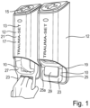
- Figure 1 shows an emergency aid material unit 10 which is accommodated in a dispenser 12.
- a dispenser 12 which is accommodated in a dispenser 12.
- Emergency aid material unit 10 is provided.
- the dispenser is marked with the inscription "Traumaset” or similar, which is provided with the reference number 13, in order to draw attention to the contents.
- the internationally customary sign of the cross is applied to the dispenser (reference number 15), which indicates materials for emergency aid.
- the dispenser 12 comprises a housing 17 and a housing opening 19, wherein the housing opening 19 is formed, among other things, by the fact that the front side 21, which faces the user during use, is shortened in the longitudinal direction of the dispenser 12, so that a handle element 23 of the emergency aid material unit 10 protrudes downwards from the housing 17 in the figurative representation.
- the handle element 23 is designed like a bracket 25 and can in particular be marked in color or also reinforced in order to ensure easy recognition and to make the function clear and recognizable.
- the bow-like handle element 23 is designed in such a way that the two side parts 25a and 25b are each hinged to a receiving compartment 27 of the emergency aid material unit 10, thus forming an opening 29 between the handle element 23 and the receiving compartment 27, into which the fingers of a hand can engage, as shown in the illustration for the left dispenser 12, and in the present arrangement the emergency aid material unit 10 can be moved in the direction of can be pulled out from the dispenser 12 at the bottom.
- the emergency aid material unit 10 comprises Figure 1 two film sections which, when placed on top of one another, form two receiving spaces 35 of two receiving compartments 31, 33 by welding, whereby the receiving compartments in the present case are connected via film hinges.
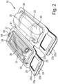
- the emergency aid material unit 10 is in Figure 2 shown in the state taken out of the dispenser, with two receiving compartments 31 and 33 being provided, each designed to form a receiving space 35 for the emergency aid material, with the receiving space 35 being sealed on all sides by thermal or ultrasonic welding or other known measures and enclosing the emergency aid material.
- the peripheral seam is provided with the reference number 37.
- the receiving compartments 31 and 33 are designed as film packaging and can be evacuated and sterilized if necessary.
- the handle elements 23 are also formed by the film layers, with reinforcing elements being able to be applied in the area of the handle elements 23 and areas of the film layers being able to be punched out to form a handle opening 29.
- Each handle element 23 consists of two layers 23a and 23b, which are arranged flatly one above the other and thus form the handle element 23. Due to the provision of two receiving compartments 31, 33, this results in a total of four handle layers 23a, b, c, d, which, when the emergency aid material unit 10 is received in the dispenser 12, all arranged one above the other and form a common handle element 23. As a result, the handle element 23 has sufficient robustness to enable the emergency aid material unit 10 to be removed from the dispenser 12 without the emergency aid material unit 10 being accidentally destroyed even when a certain amount of force is applied.
- Plastic trays 38 are accommodated in each of the receiving compartments 35, in which the emergency aid material is presented and arranged.
- bandage material 39 for applying a pressure bandage is provided in one of the receiving compartments 31 and a binding device 40 is provided in the second receiving compartment 33.
- the materials provided in the receiving compartments 31 and 33 can be marked accordingly by applying a lettering so that a user immediately knows what is provided in which compartment 31, 33.
- a film hinge 41 is formed between the receiving compartments 31 and 33, which enables an articulated connection of the two receiving compartments 31, 33, so that the two receiving compartments 31 and 33, when received in the dispenser 12, can be placed on top of one another with the back of their plastic shells 38, so that the four handle layers 23a, 23b, 23c and 23d complement each other to form a single handle element 23.
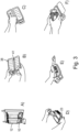
- Figure 3 shows the application of an emergency aid material unit 10 according to the invention.
- Figure 3 shows in figures A), B), C), D), E) to F).
- Figure A) the Removal of the emergency aid material unit 10 from the dispenser 12 according to Figure 1 .
- the emergency aid material units 10 are held in the dispenser 12 in such a way that they are secured against accidental removal or falling out, but at the same time easy removal is possible.
- the film hinge 41 is pivoted in such a way that the backs of the plastic shells 38 face the user.
- Instructions for use are provided on the backs of the plastic shells 38. These can be printed on the film material or, if provided, on the plastic shells, or can be enclosed loosely, which is shown in the Figures 3B and C
- the receiving compartments 31, 33 are now opened by holding one of the layers 23a of a handle element 23 and pulling the other layer in the opposite direction in the manner of a peeling movement, so that the peripheral seam 37 is either destroyed or the film material within the peripheral seam is destroyed, so that the emergency aid material provided in the receiving space 35, as shown in Figure 3E ) shown.
- the handle element 23 serves as an opening aid. The emergency aid material is then available for emergency aid.
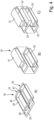
- FIG 4 shows a design in which Figure 4A ) an emergency aid material unit 10 as described in Figure 2 shown.
- the emergency aid material unit 10 is provided here in the form of two blister packs, wherein a shell element 43 is provided for each receiving compartment 31 and 33 and the shell element is covered and closed by a cover element 45.
- the handle element 23 is not designed in two layers.
- the cover element 45 is designed such that it extends over both shell elements 43 and forms the handle elements 23 by the cover element 45 extending over the shell element 43 in such a way that a bow-like handle element 23 is formed by making a cutout 29.
- a film hinge 41 is then provided, which enables the two receiving compartments to be folded onto one another.
- Figure 4B now shows an alternative design in which the two blister packs that form the receiving compartments 31, 33 are not integrally connected to one another via a film hinge, but are separated from one another and are fixed to one another in another way, for example via magnets, or alternatively via adhesive or welding points, whereby the fixation should be such that it can be released without great effort after the emergency aid material unit 10 has been removed from a dispenser 12.
- the cohesion should be so secure that, if used with a
- Dispenser 12 is provided, the two receiving compartments 31 and 33 do not separate from each other unintentionally.
- FIG 4C finally shows a design in which an extension compartment 47 is provided between the receiving compartments 31 and 33, which in turn are held together with magnets, which comes to lie between the cover elements 45 of the receiving compartments 31, 33, so that the handle elements 23 of the two receiving compartments 31 and 33 are spaced from one another by the thickness of the extension compartment 47.
- FIG. 5 now shows the dispenser 12 on the right in the drawing in the assembled and mounted state, as well as on the left in the drawing in the opened state.
- the dispenser comprises a rear wall 50 and a cover 52, which together form the dispenser housing 17.
- the connection between the rear wall 50 and the cover 52 is made via locking elements 56, which are provided in both the cover 52 and the rear wall 52.
- the rear wall 50 also has a cover element 58 on which the previously described cross symbol 15 is arranged to identify the emergency aid material unit 10.
- the rear wall 50 is visible in the area of the housing opening 19 in the assembled state.
- a holding device 60 is provided, which has a fastening opening 62, which in Figure 2 shown in the The fastening opening 62 is preferably provided on the side of the emergency aid material unit facing away from the handle element 23.
- the removal of the emergency aid material unit 10 from the dispenser 12 takes place by destroying a material bridge 64 (see Figure 2 ), which tears when the emergency aid material unit is pulled out downwards.
- appropriate material weakenings can be provided in order to adjust the desired removal force.
- the housing is separated into its components, rear wall 50 and cover 52, so that the fastening opening 62 of the emergency aid material unit 10 can then be suspended via the holding element 60 and the cover is then attached to the rear wall 50, so that then, as in Figure 1 shown, the handle element 23 of the emergency aid material unit 10 is visible in the area of the housing opening 19.
- FIG 6 shows a design in which the dispenser with the emergency aid material unit arranged therein is shown in an exploded view.
- the dispenser 12 consists of the cover 52 and the rear wall 50, with a lid element 51 being provided as part of the rear wall.
- the cover 52 and rear wall 50 are connected to one another via the locking elements 56, which are provided on both the cover ( Figure 5 ) and on the rear wall 50, are connected to one another in a detachable, snap-in manner.
- the emergency aid material unit 10 consists of the two receiving compartments 31 and 33 and has the handle element 23 protruding from the opening 19 of the dispenser.
- a fastening opening 62 is provided which engages over a corresponding holding element 60, whereby a material bridge 64 is destroyed when the emergency aid material unit 10 is pulled out in the direction of arrow 63, so that the emergency aid material unit 10 can be removed from the dispenser 12.
- Figure 7A shows an alternative design of a dispenser 80 with an additional protective element 81 in the closed state.
- the protective element 81 is pivotably connected to the housing rear wall 50 via a hinge-like connection 84.
- the protective element covers the handle element 23 in the manner of a covering means.
- the protective element 81 is flush with the outer edges of Housing rear panel 50 and housing cover 52 and thus completes the housing to form a closed design.
- Figure 7B shows the same alternative design of a dispenser 80 with an additional protective element 81 in the open state.
- the protective element 81 has a closure element 83 on its front edge 82 which ends with the housing cover 52, which is designed in such a way that it can be exposed on the inside of the front edge 84 of the housing cover 52, e.g. it can be held there with a force fit or a form fit.
- the protective element 81 is permanently connected to the housing rear wall 50 via a hinge-like connection 84.
- FIG 8 now shows an alternative design of a dispenser, which is provided here with the reference number 70.
- the dispenser 70 contains a housing 72 consisting of a cover element 74 and a frame element 76 as well as a rear wall 78, which are shown in an exploded view in Figure 6B.
- the handle elements 80 shown in Figures 6A and 6B are provided on the frame element, by means of which the dispenser 70 can be moved.
- the frame element 76 has subdivisions in the form of compartments, wherein a receiving compartment 31, 33 in the form of a blister pack, which is bone-shaped here, can be introduced into each compartment. If necessary, the individual receiving compartments 31, 33 can then be removed from the dispenser 70.
Landscapes
- Health & Medical Sciences (AREA)
- Engineering & Computer Science (AREA)
- Biomedical Technology (AREA)
- Heart & Thoracic Surgery (AREA)
- Vascular Medicine (AREA)
- Life Sciences & Earth Sciences (AREA)
- Animal Behavior & Ethology (AREA)
- General Health & Medical Sciences (AREA)
- Public Health (AREA)
- Veterinary Medicine (AREA)
- Epidemiology (AREA)
- Packages (AREA)
Description
- Die Erfindung betrifft eine Nothilfematerialeinheit umfassend mindestens ein Aufnahmekompartment zur Aufnahme von Nothilfematerial, wobei jedes Aufnahmekompartment einen geschlossenen, öffenbaren Aufnahmeraum aufweist, der zwischen zwei entlang einer geschlossen verlaufenden Umfangsnaht verbundenen Lagen ausgebildet ist.
- Nothilfematerialeinheiten sind im Stand der Technik bekannt, und werden in verschiedenen Ausgestaltungen und Ausstattungen dargeboten. Die wohl bekannteste Art dürfte der Kfz-Verbandkasten sein, wobei derartige Verbandmaterialbehältnisse über DIN-Normen bezüglich ihrer in derartigen Materialeinheiten enthaltenen Gegenständen und Utensilien sowie weiterer Parameter definiert sind.
- Dabei soll unter Nothilfematerialeinheit eine Zusammenstellung mehrerer Nothilfematerialien, wie Verbandspäckchen, Kompressen, Binden, Abbindemittel, etc. verstanden werden, die gemeinsam konfektioniert sind. In welcher Form oder Quantität die Zusammenstellung erfolgt, soll dabei unerheblich sein.
- Beispielsweise ist aus der
EP 1 714 628 A1 ein Verbandset bekannt, bei dem eine Volumenreduktion durch Komprimierung beschrieben ist. - Eine weitere Nothilfematerialeinheit ist aus der
DE 10 2005 063 227 vorbekannt, die eine Anordnung beschreibt, bei der eine längliche Hülle quer in mindestens zwei Aufnahmekompartments unterteilt ist und die Aufnahmekompartments bewegbar miteinander verbunden sind. - Neben diesen eher auf den Kfz-Bereich gerichteten Nothilfematerialeinheiten sind Einrichtungen und Halterungen für Abbindeeinrichtungen bekannt, die beispielsweise bei militärischen Ausrüstungen oder auch im Bereich der zivilen Rettung mitgeführt werden. Eine solche Gestaltung ist in der
DE 20 2008 008 183 U1 beschrieben, die ein Tourniquet Release System offenbart. Ein weiteres Tourniquet Release System ist beispielsweise aus derUS 2014/0027480 A1 bekannt, die die Anordnung eines solchen in Holsterform zeigt, wobei die Abbindeeinheit in ein Aufnahmegehäuse, das an einer Uniform festgelegt werden kann, eingeschoben werden kann. - Schließlich beschreibt die
WO 2014/182372 A1 ein Trauma Management Kit umfassend einen einfach lösbaren Beutel, um Wundverbandmaterial aufzunehmen, sowie ein Abbindeeinrichtungsholster, das auf der Außenseite des Beutels angeordnet sein kann und eine Abbindeeinrichtung aufnimmt, sowie eine Abdeckung für das Holster, die an dem Beutel festgelegt ist. Mit einem derartigen Trauma Management Kit soll insbesondere bei einer Verletzung mit massivem Blutverlust eine erste Wundstillung bereitgestellt werden können, wobei es wichtig ist, dass der Zugang zur Abbindeeinheit noch vor dem Zugang zu den Verbandmitteln ermöglicht ist, da dies über Leben und Tod entscheiden kann. - Ferner beschreibt die
EP 0354 172 A1 eine Verpackung von saugfähigen Gegenständen, wie Windeln, mit mehreren Aufnahmefächern für die Windeln. - Die
WO 2009/036746 A2 beschreibt eine Vorrichtung zum Bevorraten und/oder Bereithalten von Nothilfematerialien mit verschieden ausgebildeten Aufnahmekompartments. - Aus der
US 5,718,245 B ist eine Einmalverpackung für Nothilfematerial mit einem gemeinsamen Aufnahmekompartment bekannt. - Der vorliegenden Erfindung stellt sich nun die Aufgabe, eine Nothilfematerialeinheit bereitzustellen, die eine einfache Zugänglichkeit zu den darin beinhalteten Nothilfematerialien ermöglicht und insbesondere vielfältige Einsatzmöglichkeiten und Anbringungsmöglichkeiten bereitstellt.
- Dabei sollen die Nothilfematerialien insbesondere zur Erstversorgung von Verletzungen dienen, wie sie insbesondere bei Traumata auftreten, die häufig mit stark blutenden Wunden einhergehen. Für solche Einsatzzwecke, die auch als Krisensituationen beschrieben werden können, ist es notwendig, einen schnellen Zugriff zu Verbandsmaterialien und insbesondere auch zu Abbindemitteln zu haben. Gerade bei stark blutenden Wunden ist es wichtig, einen hinreichenden Druck aufzubringen, so dass es besonders wünschenswert ist, eine entsprechende Einrichtung, die dies auch für Laien und weniger kräftige Personen ermöglicht, bereitzustellen.
- Neben der bekannten Bereitstellung für insbesondere in Krisensituationen tätige Personen, wie Feuerwehrleute, technische Hilfswerke, Sanitäter oder Soldaten, besteht auch der Wunsch, solche Nothilfematerialeinheiten im öffentlichen Raum anzuordnen. Die Anordnung von Nothilfematerialien, wenn auch mit anderer Zielrichtung, im öffentlichen Raum hat sich zwischenzeitlich in Form von Defibrillatoren, die in vielen öffentlichen Gebäuden angeordnet sind, in gewisser Weise etabliert.
- Die Erfindung löst diese Aufgabe durch eine Nothilfematerialeinheit gemäß Anspruch 1, wobei mindestens zwei Aufnahmekompartmente vorgesehen sind und jedes Aufnahmekompartment mindestens ein Griffelement aufweist, wobei das mindestens eine Griffelement bügelförmig ausgebildet ist. Durch ein derartiges Griffelement wird erreicht, dass eine Nothilfematerialeinheit, die in einem Holster oder einer anderen Halterung aufgenommen ist, immer auf den ersten Griff sicher am Griffelement ergriffen werden kann und so schneller im Notfall zur Verfügung steht.
- Besonders bevorzugt ist es dabei, dass mindestens eine, vorzugsweise beide Lagen, des Aufnahmekompartments mit einem Griffelement verbunden sind. Auf diese Weise ist eine besonders einfache Ausgestaltung des Griffelements möglich, nämlich, wenn das Griffelement integral mit der jeweiligen Lage, bei der es sich vorzugsweise um eine Folienschicht aus einem thermoplastischen Material, bevorzugt Polyethylen, Polypropylen, Polyamid oder Polyethylenterephthalat, einem Siegelpapier oder einer Siegelfolie handeln kann, verbunden ist. Das Griffelement kann dabei durch einen Bereich von einer oder beiden Lagen gebildet werden, der außerhalb der Umfangsnaht angeordnet ist.
- Dabei kann die Umfangsnaht beispielsweise eine thermische oder Ultraschallschweißnaht sein, die die beiden Lagen, die insbesondere als Folien ausgebildet sind, miteinander fügt, wobei die Fügung vorzugsweise so verläuft, dass der Aufnahmeraum vollumfänglich verschlossen ist, insbesondere auch flüssigkeitsdicht und insbesondere auch gas- oder bakteriendicht verschlossen ist.
- Es ist dabei vorgesehen, dass das mindestens eine Griffelement bügelförmig ausgebildet ist. Eine bügelförmige Ausbildung kann dadurch erfolgen, dass sich die Lagen nach außerhalb der Umfangsnaht erstrecken und dann eine Ausstanzung vorgenommen wird, so dass ein bügelförmiges Element der Lagen stehen bleibt.
- Besonders bevorzugt und einfach ist dabei auch eine Verpackung, bei der das Aufnahmekompartment statt aus zwei Folienlagen als Blisterverpackung ausgebildet ist und eine der Lagen als Schalenelement und die andere Lage als Deckelelement ausgebildet ist. Dabei wird das Schalenelement im Wesentlichen dreidimensional ausgebildet, wohingegen das Deckelelement im Wesentlichen flach ist und den Aufnahmeraum, der durch das Schalenelement gebildet wird, verschließt.
- In diesem Fall kann z.B. nur das Deckelement mit dem Griffelement verbunden sein.
- Es ist vorgesehen, dass mindestens zwei Aufnahmekompartments vorgesehen sind, die insbesondere miteinander verbunden sind. Durch die Vorsehung von mehr als einem Aufnahmekompartment kann das Nothilfematerial übersichtlicher und besser strukturiert dargeboten werden.
- Dabei ist es vorteilhaft vorgesehen, wenn sich die Griffelemente flächig überdecken, wobei dies sowohl gilt, sofern mehr als ein Griffelement bzw. ein aus zwei Lagen bestehendes Griffelement je Aufnahmekompartment vorgesehen sind, als auch wenn mehrere Aufnahmekompartments vorgesehen sind, die dann jeweils ein oder mehrere Griffelemente bzw. Griffelementlagen aufweisen. Dabei ist es besonders vorteilhaft, wenn die Aufnahmekompartments und/oder die Griffelemente in Richtung senkrecht zur Flächenrichtung übereinander anordenbar sind und sich in dieser Anordnung flächenmäßig überdecken. Hierdurch kann eine besonders kompakte Anordnung geschaffen werden, in der das benötigte Nothilfematerial auf besonders kleinem Raum und optisch entsprechend dargeboten werden kann.
- Eine besonders einfache Gestaltung wird dadurch geschaffen, dass die Aufnahmekompartments untereinander über ein Filmscharnier an einer vorzugsweise nicht das Griffelement aufweisenden Seitenkante verbunden sind, wobei insbesondere entlang des Filmscharniers Sollbruchstellen, insbesondere in Form von Perforationen, vorgesehen sein können. Durch eine derartige Gestaltung ist eine besonders einfache Herstellbarkeit der Aufnahmekompartments möglich. Insbesondere können diese durch eine oder zwei durchgehende Lagen gebildet oder verbunden sein und das Filmscharnier kann durch die eine Umfangsnaht ausgebildet sein, die das Aufnahmekompartment verschließt und gleichzeitig ein Filmscharnier ausbildet. Alternativ kann das Filmscharnier auch durch einen Bereich zwischen den Umfangsnähten ausgebildet sein.
- Sofern gewünscht, dass die Aufnahmekompartments einfach voneinander trennbar sind, insbesondere ohne die Aufnahmeräume zu verletzen, kann vorgesehen sein, dass entlang des Filmscharniers Sollbruchstellen, insbesondere in Form von Perforationen, vorgesehen sind.
- Statt der Verbindung der Aufnahmekompartments über Filmscharniere kann auch vorgesehen sein, dass die Aufnahmekompartments über magnetische, komplementäre Elemente miteinander lösbar verbindbar sind. Dies ermöglicht eine noch einfachere Separierung voneinander und verringert die Gefahr, dass ein Aufnahmekompartment ungewollt beim Versuch des Trennens der Aufnahmekompartments voneinander aufgerissen und somit zerstört wird.
- Darüber hinaus kann vorgesehen sein, dass zwischen den Aufnahmekompartments ein Erweiterungskompartment vorgesehen ist bzw. dazwischen eingebracht werden kann, das ebenfalls einen Aufnahmeraum aufweist, jedoch keine Griffelemente umfasst. Dieses Erweiterungsmodul kann insbesondere auch über ein Filmscharnier und/oder magnetische komplementäre Elemente mit den Aufnahmekompartments verbunden sein.
- Besonders bevorzugt ist darüber hinaus, dass mindestens eines der Aufnahmekompartments, vorzugsweise jedes der Aufnahmekompartments, eine Öffnungshilfe aufweist. Hierdurch wird die Öffnung des öffenbaren Aufnahmekompartments erleichtert und insbesondere kann auch erreicht werden, dass eine definierte Öffnungsweise erreicht wird und das Kompartment nicht in beliebiger Weise geöffnet wird bzw. schlicht zerrissen wird, wodurch Nothilfematerialien aus dem Aufnahmekompartment herausfallen können, wenn die Öffnung nicht wie gewünscht erfolgt.
- Besonders bevorzugt ist es dabei, wenn als Öffnungshilfe das Griffelement dient. Auf diese Weise können zwei Funktionen im Griffelement integriert sein.
- Weiterhin ist es besonders bevorzugt, wenn die Nothilfematerialeinheit eine Befestigungsöffnung aufweist. Diese kann insbesondere bezüglich des Aufnahmeraums dem Griffelement gegenüberliegend angeordnet sein und außerhalb des Aufnahmeraums liegen, zum Befestigen an einer Halteeinrichtung. Als derartige Halteeinrichtungen kommen sowohl Holster als auch Abgabeeinrichtungen, Dispenser, aber auch Gürtel, Uniformelemente, Schlüsselbänder oder ähnliches in Frage, an denen eine entsprechende Nothilfematerialeinheit angebracht werden kann. Alternativ sind auch andere Befestigungsmöglichkeiten denkbar, z.B. auch über das Griffelement. Weiterhin ist eine Befestigungsmöglichkeit denkbar, in der das Aufnahmekompartment über eine magnetische oder eine andere kraft- oder formschlüssige oder materialschlüssige Verbindung befestigt ist. Die Befestigungsöffnung stellt jedoch eine vergleichsweise einfache Möglichkeit dar. Insbesondere, wenn es sich um ein zerstörbares Material handelt, wobei gegebenenfalls entsprechende Schwächungen und Sollbruchstellen vorgesehen sein können, ist eine rasche Entnahme und Bereitstellung der Nothilfematerialeinheit dadurch möglich, dass diese nicht erst mühsam von einer Halteeinrichtung entfernt werden muss, sondern einfach unter Zerstörung eines die Befestigungsöffnung einschließenden Materialbereichs von der Halteeinrichtung abgerissen werden kann.
- Die Erfindung umfasst ferner einen Nothilfematerialeinheitdispenser aufweisend eine Nothilfematerialeinheit der beschriebenen Art, wobei der Dispenser ein Gehäuse zur Aufnahme der Nothilfematerialeinheit und eine Gehäuseöffnung aufweist, durch die die Nothilfematerialeinheit entnommen werden kann mit den Merkmalen des Anspruchs 15.
- Dabei ist es besonders bevorzugt, wenn Gehäuse und Gehäuseöffnung so ausgebildet sind, dass sich mindestens das eine Griffelement bei in das Gehäuse aufgenommener Nothilfematerialeinheit aus der Öffnung heraus erstreckt. Dadurch ist eine besonders einfache Entnehmbarkeit gewährleistet. Der Rest der Nothilfematerialeinheit, der nicht aus der Öffnung herausragt, bleibt durch den Nothilfematerialeinheitdispenser gut geschützt.
- Besonders bevorzugt ist es dabei, wenn das Gehäuse eine Rückwand und eine Abdeckung aufweist, die zur Bildung des Gehäuses lösbar miteinander verbindbar sind. Hierüber sind eine einfache Anbringbarkeit beispielsweise an einer Wand und eine einfache Wechselbarkeit der Nothilfematerialeinheit möglich. Insbesondere kann vorgesehen sein, dass der Nothilfematerialeinheitdispenser eine Halte- oder Trageeinrichtung aufweist, die eine Befestigungsöffnung in der Nothilfematerialeinheit bei aufgenommener Nothilfematerialeinheit durchgreift.
- In einer bevorzugten Ausführungsform weist der Nothilfematerialeinheitdispenser ein zusätzliches Schutzelement auf, welches wenigstens ein Griffelement überdeckt. Ein derartiges Schutzelement erhöht den Aufwand zur Entnahme der Nothilfematerialeinheit ohne sie zu verhindern und erschwert damit eine missbräuchliche Entnahme der Nothilfematerialeinheit. Dieses Schutzelement ist mit dem Gehäuse verbunden und muss vor der Entnahme der Nothilfematerialeinheit bewegt, z.B. verschoben oder verschwenkt oder entfernt werden, so dass das Griffelement freigelegt wird. Dabei kann dieses Element vollständig entfernt werden oder mit einem Teil des Gehäuses unlösbar verbunden bleiben, beispielsweise über eine scharnierartige Verbindung. Bevorzugt ist eine Ausgestaltung, bei der das Schutzelement scharnierartig mit der Rückwand des Gehäuses verbunden ist, und gleichzeitig lösbar mit der Abdeckung des Gehäuses verbunden ist, so dass in einem ersten Zustand das Schutzelement die gesamte oder einen Teil der Gehäuseöffnung überdeckt und insbesondere bündig mit den Außenkanten von Rückwand und Abdeckung abschließt. Das Schutzelement wirkt daher als öffenbares Abdeckungsmittel für die Gehäuseöffnung. D.h. das Schutzelement verschließt oder verkleinert die Gehäuseöffnung.
- Die lösbare Verbindung des Schutzelements mit dem Gehäuse kann kraftschlüssig, formschlüssig oder stoffschlüssig erfolgen. Das Schutzelement kann aus einem beliebigen Material gefertigt sein, bevorzugt jedoch aus einem transparenten Kunststoff, beispielsweise Polyethylen, Polypropylen, Polyamid, Polycarbonat, Polyester, Polyethylenterephthalat. Dieses Schutzelement kann mit einer zusätzlichen Vorrichtung versehen sein, die die Entfernung des Schutzelements erleichtert, beispielsweise eine Grifföffnung oder Griffmulde oder ein Griffelement in Form eines vorstehenden Materialabschnitts oder Henkels.
- Grundsätzlich ist es auch denkbar, dass die Entfernung des Schutzelements nicht wie beschrieben wiederholt möglich ist, sondern dass das Schutzelement bei der Entfernung zerstört werden muss. Es kann dabei vorgesehen sein, dass hierzu Hilfsmittel vorgesehen sind.
- Darüber hinaus kann der Nothilfematerialeinheitdispenser weitere Elemente aufweisen, wie insbesondere eine optische oder akustische Signaleinrichtung, eine Kameraeinrichtung, mit der Videos oder Bilder vom Unfallort erstellt werden können, und/oder eine Codierung. Darüber hinaus kann auch eine Kommunikationseinrichtung vorgesehen sein. Als Nothilfematerialien können beispielsweise Einweghandschuhe, Verbandmaterialien, aber auch eine Patiententransferunterlage, eine Rettungsdecke und/oder ein Thoraxpflaster mit Ventil, sowie ein Beatmungstubus und/oder ein Mundschutz vorgesehen sein. Weitere mögliche Nothilfematerialien sind eine Abbindeeinrichtung, eine Blutverlustschablone, mittels derer beispielsweise der Laie eine Analogie zum Blutverlust geben kann, so dass wichtige und wertvolle Informationen für die Aufnahme in ein Krankenhaus gegeben werden. Ferner können Patientenmarkierungen, beispielsweise in Form von Flaggen, vorgesehen sein, ähnlich wie bei der Lawinenrettung. Hierüber ist gegebenenfalls auch eine Markierung und Priorisierung über den Schweregrad oder die Art der Verletzung möglich. Wie bereits ausgeführt, kann die Nothilfematerialeinheit in einem
- Nothilfematerialeinheitdispenser untergebracht sein, und so insbesondere im öffentlichen Raum, wie beispielsweise in Banken, Sporteinrichtungen, Schulen, etc. vorgesehen und sichtbar für den Bedarfsfall dargeboten werden. Eine Benutzung ist darüber hinaus auch ohne Nothilfematerialeinheitdispenser möglich. Beispielsweise als Teil einer Ausrüstung von zivilen Personen und/oder der Polizei bzw. Rettungskräften. In diesem Fall kann eine Halterung über die Griffelemente und/oder über eine, sofern vorgesehen, Befestigungsöffnung erfolgen. Darüber hinaus lässt sich eine derartige Nothilfematerialeinheit gegebenenfalls auch mittels Drohnen an einen Bedarfsort bringen.
- Sofern das Notfhilfeverbandset mehr als ein Aufnahmekompartment aufweist, ist es besonders vorteilhaft, wenn jedes Aufnahmekompartment mit verschiedenen Nothilfematerialien bestückt ist. So kann beispielsweise das eine Aufnahmekompartment eine Abbindeeinrichtung und das andere Kompartment weitere Maßnahmen zur Blutstillung und Wundversorgung aufweisen.
- Darüber hinaus kann der Nothilfematerialeinheitdispenser auch weitere Hilfsmittel für den Nothilfefall, wie optische oder akustische Signal- oder Sendeeinrichtung aufweisen. Ferner kann ein Code, z.B. ein QR-Code vorgesehen sein, dem Informationen, z.B. Standort, entnommen werden können. Schließlich sind auch Kameraeinrichtungen bekannt. Der Nothilfematerialeinheitdispenser kann zur besseren Auffindbarkeit Markierungen, z.B. in Form des bekannten "Kreuzes" aufweisen.
- Nach einer weiteren alternativen Ausgestaltung ist es auch möglich, eine Vielzahl von Aufnahmekompartments vorzusehen, die in einem Nothilfematerialeinheitdispenser untergebracht sind, wobei der Nothilfematerialeinheitdispenser hier vorzugsweise so ausgestaltet ist, dass er als Ganzes vom Aufbewahrungsort gelöst werden kann und mittels Tragevorrichtung zum Bedarfsort gebracht wird. ++++++++ Weitere Vorteile und Nachteile ergeben sich aus der nachfolgenden Figurenbeschreibung sowie der übrigen Beschreibung und den Ansprüchen. Sämtliche Merkmale sind dabei sowohl für sich alleine als auch in Kombination erfindungswesentlich.
- Dabei zeigen:
-
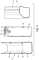
Figur 1 eine erste Ausgestaltung eines Dispensers mit Nothilfematerialeinheit; -
Figur 2 eine erste Ansicht der Nothilfematerialeinheit; -
Figur 3
A bis F eine Verwendung der Nothilfematerialeinheit; -
Figur 4
A bis C verschiedene Varianten der Nothilfematerialeinheit; -
Figur 5 den Dispenser gemäßFigur 1 in einer geöffneten Darstellung; -
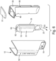
Figur 6 eine Explosionsdarstellung des Dispensers mit Nothilfematerialeinheit; -
Figur 7
A und B eine alternative Gestaltung eines Dispensers mit einem zusätzlichem Schutzelement als Diebstahlsicherung und -
Figur 8
A und B eine alternative Gestaltung eines Dispensers. -
Figur 1 zeigt eine Nothilfematerialeinheit 10, die in einem Dispenser 12 aufgenommen ist. In der vorliegenden Ausgestaltung gemäßFigur 1 sind hierbei unmittelbar nebeneinander zwei Dispenser mit jeweils einer - Nothilfematerialeinheit 10 vorgesehen. Der Dispenser ist durch Aufbringen eines Schriftzugs (Markierung) "Traumaset" oder ähnliches, der mit dem Bezugszeichen 13 versehen ist, gekennzeichnet, um auf den Inhalt aufmerksam zu machen. Darüber hinaus ist auf dem Dispenser das international übliche Zeichen des Kreuzes angebracht (Bezugszeichen 15), das auf Materialien zur Nothilfe hinweist.
- In jedem der Dispenser 12 ist eine Nothilfematerialeinheit 10 vorgesehen. Der Dispenser 12 umfasst dabei ein Gehäuse 17 und eine Gehäuseöffnung 19, wobei die Gehäuseöffnung 19 u.a. dadurch gebildet wird, dass die Vorderseite 21, die bei Gebrauch dem Benutzer zugewandt ist, in Längsrichtung des Dispensers 12 verkürzt ausgebildet ist, so dass ein Griffelement 23 der Nothilfematerialeinheit 10 aus dem Gehäuse 17 in der figürlichen Darstellung nach unten herausragt. Das Griffelement 23 ist dabei bügelartig 25 ausgebildet und kann insbesondere farbig gekennzeichnet oder auch verstärkt ausgebildet sein, um eine leichte Erkennbarkeit zu gewährleisten und die Funktion deutlich zu machen und zu erkennen.
- Das bügelartige Griffelement 23 ist so ausgebildet, dass die beiden Seitenteile 25a und 25b jeweils an einem Aufnahmekompartment 27 der Nothilfematerialeinheit 10 angelenkt sind und sich so zwischen dem Griffelement 23 und dem Aufnahmekompartment 27 eine Öffnung 29 ausbildet, in die die Finger einer Hand, wie bei dem linken Dispenser 12 in der Darstellung gezeigt, eingreifen können und in der vorliegenden Anordnung die Nothilfematerialeinheit 10 nach unten aus dem Dispenser 12 herausziehen können. Die Nothilfematerialeinheit 10 umfasst dabei in
Figur 1 zwei Folienabschnitte, die übereinandergelegt durch Miteinanderverschweißen zwei Aufnahmeräume 35 zweier Aufnahmekompartments 31, 33 ausbilden, wobei die Aufnahmekompartments im vorliegenden Fall über Filmscharniere verbunden sind. Die Nothilfematerialeinheit 10 ist dabei inFigur 2 in aus dem Dispenser herausgenommenen Zustand gezeigt, wobei hier zwei Aufnahmekompartments 31 und 33 vorgesehen sind, die jeweils durch die Bildung eines Aufnahmeraums 35 für das Nothilfematerial gestaltet sind, wobei der Aufnahmeraum 35 durch eine Umfangsnaht, die durch thermisches oder Ultraschallverschweißen oder weitere bekannte Maßnahmen allseitig abgeschlossen ist und das Nothilfematerial in sich einschließt. Die Umfangsnaht ist mit dem Bezugszeichen 37 versehen. Die Aufnahmekompartments 31 und 33 sind dabei als Folienverpackung gestaltet und können gegebenenfalls evakuiert und sterilisiert werden. Ebenfalls durch die Folienlagen werden die Griffelemente 23 gebildet, wobei im Bereich der Griffelemente 23 Verstärkungselemente aufgebracht sein können und zur Bildung einer Grifföffnung 29 Bereiche der Folienlagen ausgestanzt werden können. - Jedes Griffelement 23 besteht dabei aus zwei Lagen 23a und 23b, die flächig übereinander angeordnet sind und so das Griffelement 23 ergeben. Aufgrund der Vorsehung von zwei Aufnahmekompartments 31, 33 resultiert dies in insgesamt vier Grifflagen 23a, b, c, d, die in dem in den Dispenser 12 aufgenommenen Zustand der Nothilfematerialeinheit 10 allesamt übereinander angeordnet sind und ein gemeinsames Griffelement 23 bilden. Hierdurch besitzt das Griffelement 23 eine hinreichende Robustheit, um ein Entnehmen der Nothilfematerialeinheit 10 aus dem Dispenser 12 zu ermöglichen, ohne dass auch bei Anwendung einer gewissen Kraft die Nothilfematerialeinheit 10 in ungewollter Weise zerstört wird.
- In die Aufnahmeräume 35 sind jeweils Kunststoffschalen 38 aufgenommen, in denen das Nothilfematerial dargeboten und angerichtet ist. Im vorliegenden Fall ist in einem der Aufnahmekompartments 31 Bindenmaterial 39 zum Anlegen eines Druckverbandes vorgesehen und in dem zweiten Aufnahmekompartment 33 eine Abbindeeinrichtung 40. Die in den Aufnahmekompartments 31 und 33 vorgesehenen Materialien können durch Aufbringung eines Schriftzugs entsprechend gekennzeichnet sein, so dass ein Benutzer sofort weiß, was in welchem Kompartment 31, 33 vorgesehen ist. Durch die Umfangsnaht 37, die die Aufnahmeräume 35 umschließt, bildet sich zwischen den Aufnahmekompartments 31 und 33 ein Filmscharnier 41 aus, das eine gelenkige Verbindung der beiden Aufnahmekompartments 31, 33 ermöglicht, so dass die beiden Aufnahmekompartments 31 und 33 im in den Dispenser 12 aufgenommenen Zustand aufeinandergelegt werden können mit der Rückseite ihrer Kunststoffschalen 38, so dass sich die vier Grifflagen 23a, 23b, 23c und 23d zu einem einzigen Griffelement 23 ergänzen.
-
Figur 3 zeigt den Anwendungsfall einer erfindungsgemäßen Nothilfematerialeinheit 10.Figur 3 zeigt in den Abbildungen A), B), C), D), E) bis F). Abbildung A) die Entnahme der Nothilfematerialeinheit 10 aus dem Dispenser 12 gemäßFigur 1 . - Die Nothilfematerialeinheiten 10 sind dabei im Dispenser 12 so gehalten, dass diese gegen versehentliches Herausnehmen oder Herausfallen gesichert sind, gleichwohl jedoch ein einfaches Entnehmen möglich ist.
- Im nächsten Schritt erfolgt dann eine Verschwenkung um das Filmscharnier 41 in einer Weise, dass die Rückseiten der Kunststoffschalen 38 in Richtung des Benutzers weisen. Auf den Rückseiten der Kunststoffschalen 38 sind Gebrauchsanleitungen vorgesehen. Diese können z.B. auf das Folienmaterial oder, sofern vorgesehen, die Kunststoffschalen aufgedruckt sein oder auch lose beiliegen, was in den
Figuren 3B und C gezeigt ist. Zum Herausnehmen der Nothilfematerialien aus den Aufnahmeräumen 35 werden nun die Aufnahmekompartments 31, 33 geöffnet, indem eine der Lagen 23a eines Griffelements 23 festgehalten wird und die andere Lage in der Art einer Peelbewegung in die entgegengesetzte Richtung gezogen wird, so dass die Umfangsnaht 37 entweder zerstört wird oder das Folienmaterial innerhalb der Umfangsnaht zerstört wird, so dass das in dem Aufnahmeraum 35 vorgesehen Nothilfematerial, wie inFigur 3E ) gezeigt, entnommen werden kann. Das Griffelement 23 dient hier als Öffnungshilfe. Das Nothilfematerial steht dann zur Nothilfeleistung zur Verfügung. -
Figur 4 zeigt eine Gestaltung, bei der inFigur 4A ) eine Nothilfematerialeinheit 10, wie sie inFigur 2 gezeigt ist, ähnlich ist. Die Nothilfematerialeinheit 10 ist hier jedoch in Form von zwei Blisterpackungen vorgesehen, wobei ein Schalenelement 43 je Aufnahmekompartment 31 und 33 vorgesehen ist und das Schalenelement durch ein Deckelelement 45 überdeckt und verschlossen wird. Im vorliegenden Fall ist das Griffelement 23 nicht doppellagig ausgebildet. Das Deckelelement 45 ist dabei so ausgebildet, dass es sich über beide Schalenelemente 43 erstreckt und die Griffelemente 23 ausbildet, indem das Deckelelement 45 sich über das Schalenelement 43 hinübererstreckt, in einer Form, dass durch Anbringen einer Ausstanzung 29 jeweils ein bügelartiges Griffelement 23 gebildet wird. Im Bereich zwischen den beiden Aufnahmekompartments 31 und 33 ist dann wiederum ein Filmscharnier 41 vorgesehen, das eine Klappbarkeit der beiden Aufnahmekompartments aufeinander ermöglicht. -
Figur 4B zeigt nun eine alternative Gestaltung, bei der die beiden Blisterverpackungen, die die Aufnahmekompartments 31, 33 bilden, nicht über ein Filmscharnier integral miteinander verbunden sind, sondern voneinander separiert sind und in anderer Weise beispielsweise über Magnete, oder auch alternativ über Klebe- oder Schweißpunkte, aufeinander fixiert sind, wobei die Fixierung so erfolgen sollte, dass sie ohne großen Kraftaufwand nach Entnahme der Nothilfematerialeinheit 10 aus einem Dispenser 12 aufgelöst werden kann. Darüber hinaus sollte der Zusammenhalt so sicher sein, dass, sofern eine Verwendung mit einem - Dispenser 12 vorgesehen ist, die beiden Aufnahmekompartments 31 und 33 sich nicht ungewollt voneinander trennen.
-
Figur 4C zeigt schließlich eine Gestaltung, bei der zwischen den Aufnahmekompartments 31 und 33, die wiederum mit Magneten zusammengehalten werden, noch ein Erweiterungskompartment 47 vorgesehen ist, das zwischen den Deckelelementen 45 der Aufnahmekompartments 31, 33 zu liegen kommt, so dass die Griffelemente 23 der beiden Aufnahmekompartments 31 und 33 um die Dicke des Erweiterungskompartments 47 voneinander beabstandet sind. -
Figur 5 zeigt nun den Dispenser 12 zum einen rechts in der Zeichnungsdarstellung im zusammengebauten und montierten Zustand, so wie links in der Zeichnungsdarstellung im geöffneten Zustand. Der Dispenser umfasst dabei eine Rückwand 50 sowie eine Abdeckung 52, die gemeinsam das Dispensergehäuse 17 ausbilden. Die Verbindung zwischen Rückwand 50 und Abdeckung 52 erfolgt dabei über Rastelemente 56, die korrespondierend sowohl in der Abdeckung 52 als auch in der Rückwand 52 vorgesehen sind. Die Rückwand 50 trägt im vorliegenden Fall auch ein Deckelelement 58 auf der das zuvor beschriebene Kreuz-Symbol 15 zur Kennzeichnung der Nothilfematerialeinheit 10 angeordnet ist. Die Rückwand 50 ist im Bereich der Gehäuseöffnung 19 im zusammengebauten Zustand sichtbar. Abgewandt von der Gehäuseöffnung 19 an der Rückwand 50 ist eine Halteeinrichtung 60 vorgesehen, die eine Befestigungsöffnung 62, die inFigur 2 gezeigt ist, in der Nothilfematerialeinheit durchgreifen kann. Die Befestigungsöffnung 62 ist dabei vorzugsweise an der dem Griffelement 23 abgewandten Seite der Nothilfematerialeinheit vorgesehen. Das Entnehmen der Nothilfematerialeinheit 10 aus dem Dispenser 12 erfolgt dabei unter Zerstörung einer Materialbrücke 64 (s.Figur 2 ), die beim nach unten Herausziehen der Nothilfematerialeinheit zerreißt. Hierzu können insbesondere entsprechende Materialschwächungen vorgesehen sein, um die gewünschte Entnahmekraft einzustellen. - Auf diese Weise kann eine sichere Halterung gegen unbeabsichtigtes Herausfallen bei gleichzeitig einfacher Gestaltung realisiert werden. Zum Befüllen des Dispensers 12 wird dabei das Gehäuse in seine Bestandteile Rückwand 50 und Abdeckung 52 getrennt, so dass dann über das Halteelement 60 die Befestigungsöffnung 62 der Nothilfematerialeinheit 10 aufgehängt werden kann und dann die Abdeckung wiederum auf der Rückwand 50 angebracht wird, so dass dann, wie in
Figur 1 gezeigt, das Griffelement 23 der Nothilfematerialeinheit 10 im Bereich der Gehäuseöffnung 19 sichtbar ist. - Weitere Möglichkeiten des Mitsichführens der Nothilfematerialeinheit sind dabei über Tragen am Griffelement 23, aber auch Festlegen mittels eines Schlüsselbandes oder einer Gürteltrageeinrichtung, die entweder in das Griffelement 23 oder die Befestigungsöffnung 62 eingreifen können. Darüber hinaus ist über das Griffelement 23 sowie die Befestigungsöffnung 62 auch ein Transport beispielsweise mittels Drohnen möglich.
-
Figur 6 zeigt eine Gestaltung, bei der der Dispenser mit der darin angeordneten Nothilfematerialeinheit in einer Explosionsdarstellung gezeigt ist. Der Dispenser 12 besteht dabei aus der Abdeckung 52 sowie der Rückwand 50, wobei ein Deckelelement 51 als Teil der Rückwand vorgesehen ist. Abdeckung 52 und Rückwand 50 werden über die Rastelemente 56, die sowohl an der Abdeckung (Figur 5 ) als auch an der Rückwand 50 vorgesehen sind, miteinander lösbar rastend verbunden. Die Nothilfematerialeinheit 10 besteht dabei aus den zwei Aufnahmekompartments 31 und 33 und weist das aus der Öffnung 19 des Dispensers hinausragende Griffelement 23 auf. Zur Befestigung am Dispenser ist eine Befestigungsöffnung 62 vorgesehen, die ein entsprechendes Halteelement 60 übergreift, wobei eine Materialbrücke 64 bei Herausziehen der Nothilfematerialeinheit 10 in Pfeilrichtung 63 zerstört wird, so dass die Nothilfematerialeinheit 10 aus dem Dispenser 12 entnommen werden kann. -
Figur 7A zeigt eine alternative Gestaltung eines Dispensers 80 mit einem zusätzlichen Schutzelement 81 in geschlossenem Zustand. Das Schutzelement 81 ist über eine scharnierartige Verbindung 84 mit der Gehäuserückwand 50 verschwenkbar verbunden. Dabei überdeckt das Schutzelement das Griffelement 23 in der Art eines Abdeckungsmittels. Das Schutzelement 81 schließt bündig mit den Außenkanten von Gehäuserückwand 50 und Gehäuseabdeckung 52 ab und ergänzt somit das Gehäuse zu einer geschlossenen Gestaltung. -
Figur 7B zeigt dieselbe alternative Gestaltung eines Dispensers 80 mit einem zusätzlichen Schutzelement 81 in geöffneten Zustand. Das Schutzelement 81 weist an seiner mit der Gehäuseabdeckung 52 abschließenden Vorderkante 82 ein Verschlusselement 83 auf, welches so ausgestaltet ist, dass es auf der Innenseite der vorderen Kante 84 der Gehäuseabdeckung 52 freigelegt werden kann, z.B. dort kraft- oder formschlüssig hält. Das Schutzelement 81 ist über eine scharnierartige Verbindung 84 mit der Gehäuserückwand 50 unlösbar verbunden. -
Figur 8 zeigt nun eine alternative Gestaltung eines Dispensers, der hier mit dem Bezugszeichen 70 versehen ist. Der Dispenser 70 enthält ein Gehäuse 72 bestehend aus einem Abdeckelement 74 und einem Rahmenelement 76 sowie einer Rückwand 78, die in einer Explosionsdarstellung in Figur 6B gezeigt sind. Am Rahmenelement sind die in Figur 6A und 6B gezeigten Griffelemente 80 vorgesehen, mittels derer der Dispenser 70 bewegt werden kann. Das Rahmenelement 76 weist Unterteilungen in Form von Fächern auf, wobei in jedem Fach ein Aufnahmekompartment 31, 33 in Form einer Blisterverpackung, die hier knochenförmig ausgebildet ist, eingebracht werden kann. Im Bedarfsfall können dann die einzelnen Aufnahmekompartments 31, 33 aus dem Dispenser 70 entnommen werden.
Claims (20)
- Nothilfematerialeinheit (10), wobei eine Nothilfematerialeinheit (10) eine Zusammenstellung mehrerer Nothilfematerialien, die gemeinsam konfektioniert sind, umfasst, umfassend mindestens ein Aufnahmekompartment (31, 33) zur Aufnahme von Nothilfematerial, wobei jedes Aufnahmekompartment (31, 33) einen geschlossenen, öffenbaren Aufnahmeraum (35) aufweist, der zwischen zwei entlang einer geschlossen verlaufenden Umfangsnaht (37) verbundenen Lagen ausgebildet ist, dadurch gekennzeichnet, dass mindestens zwei Aufnahmekompartments (31, 33) vorgesehen sind, wobei jedes der Aufnahmekompartments (31, 33) mindestens ein Griffelement (23) aufweist und wobei das mindestens eine Griffelement (23) bügelförmig (25) ausgebildet ist.
- Nothilfematerialeinheit nach Anspruch 1, dadurch gekennzeichnet, dass mindestens eine, vorzugsweise beide Lagen des Aufnahmekompartments (31, 33) mit einem Griffelement (23) verbunden ist.
- Nothilfematerialeinheit nach Anspruch 1 oder 2, dadurch gekennzeichnet, dass das mindestens eine Griffelement (23) integral mit der jeweiligen Lage außerhalb des Aufnahmeraums (35) verbunden ist.
- Nothilfematerialeinheit nach einem der vorstehenden Ansprüche, dadurch gekennzeichnet, dass sich das mindestens eine Griffelement (23) ausgehend von der Umfangsnaht (37) insbesondere in Flächenrichtung der Lagen erstreckt.
- Nothilfematerialeinheit nach einem der vorstehenden Ansprüche, dadurch gekennzeichnet, dass das mindestens eine Aufnahmekompartment (31, 33) als Blisterverpackung ausgebildet ist und eine der Lagen als Schalenelement (43) und die andere Lage als Deckelelement (45) ausgebildet ist.
- Nothilfematerialeinheit nach einem der vorstehenden Ansprüche, dadurch gekennzeichnet, dass die Lagen aus Kunststofffolie bestehen, insbesondere aus Polyamid, Polypropylen, Polyethylen oder Polyethylenterephthalat.
- Nothilfematerialeinheit nach einem der vorstehenden Ansprüche, dadurch gekennzeichnet, dass die mindestens zwei Aufnahmekompartments (31, 33) miteinander verbunden oder verbindbar sind, vorzugsweise lösbar verbindbar sind.
- Nothilfematerialeinheit nach einem der vorstehenden Ansprüche, dadurch gekennzeichnet, dass die Griffelemente (23) insbesondere einander flächig überdeckend ausgebildet sind.
- Nothilfematerialeinheit nach einem der vorstehenden Ansprüche, dadurch gekennzeichnet, dass die Aufnahmekompartments (31, 33) und/oder die Griffelemente (23) in Richtung senkrecht zur Flächenrichtung übereinander anordenbar sind und sich in dieser Anordnung flächenmäßig überdecken.
- Nothilfematerialeinheit nach einem der vorstehenden Ansprüche, dadurch gekennzeichnet, dass die Aufnahmekompartments (31, 33) untereinander über ein Filmscharnier (41) insbesondere an einer nicht das Griffelement (23) aufweisenden Seitenkante verbunden sind, wobei insbesondere entlang des Filmscharniers (41) Sollbruchstellen, insbesondere in Form von Perforationen vorgesehen sind.
- Nothilfematerialeinheit nach einem der vorstehenden Ansprüche, dadurch gekennzeichnet, dass die Aufnahmekompartments (31, 33) über magnetische komplementäre Elemente miteinander lösbar verbindbar sind.
- Nothilfematerialeinheit nach einem der vorstehenden Ansprüche, dadurch gekennzeichnet, dass mindestens eins der Aufnahmekompartements (31, 33) eine Öffnungshilfe aufweist.
- Nothilfematerialeinheit nach einem der vorstehenden Ansprüche, dadurch gekennzeichnet, dass als Öffnungshilfe das Griffelement (23) dient.
- Nothilfematerialeinheit nach einem der vorstehenden Ansprüche, dadurch gekennzeichnet, dass eine Befestigungsöffnung vorgesehen ist, insbesondere bezüglich des Aufnahmeraums (35) dem Griffelement (23) gegenüberliegend, die außerhalb des Aufnahmeraums liegt, zum Befestigen an einer Halteeinrichtung.
- Nothilfematerialeinheitdispenser, aufweisend eine Nothilfematerialeinheit (10), ein Gehäuse (17) zur Aufnahme der Nothilfematerialeinheit (10) und eine Gehäuseöffnung (19), durch die die Nothilfematerialeinheit (10) entnommen werden kann, dadurch gekennzeichnet, dass die Nothilfematerialeinheit (10) mindestens ein Aufnahmekompartment (31, 33) zur Aufnahme von Nothilfematerial umfasst, wobei jedes Aufnahmekompartment (31, 33) einen geschlossenen, öffenbaren Aufnahmeraum (35) aufweist, der zwischen zwei entlang einer geschlossen verlaufenden Umfangsnaht (37) verbundenen Lagen ausgebildet ist und wobei mit mindestens einem Aufnahmekompartment (31, 33) ein Griffelement (23) verbunden ist und die Nothilfematerialeinheit die Merkmale der Ansprüche 1 bis 14 aufweist.
- Nothilfematerialeinheitdispenser nach Anspruch 15, dadurch gekennzeichnet, dass das Gehäuse (17) und die Gehäuseöffnung (19) so ausgebildet ist, dass sich die Griffelemente (23) bei in das Gehäuse (17) aufgenommener Nothilfematerialeinheit (10) aus der Gehäuseöffnung (15) heraus erstrecken.
- Nothilfematerialeinheitdispenser nach Anspruch 15 oder 16, dadurch gekennzeichnet, dass das Gehäuse (17) eine Rückwand (54) und eine Abdeckung (52) aufweist, die zur Bildung des Gehäuses (17) lösbar miteinander verbindbar sind.
- Nothilfematerialeinheitdispenser nach einem der vorangehenden Ansprüche 15 bis 17, dadurch gekennzeichnet, dass das Gehäuse ein Schutzelement (81) aufweist, das die Gehäuseöffnung (19) verschließt oder verkleinert und wobei das Schutzelement (81) insbesondere verschwenkbar an dem Gehäuse (17) gehalten ist.
- Nothilfematerialeinheitdispenser nach einem der vorangehenden Ansprüche 15 bis 18, dadurch gekennzeichnet, dass der Dispenser (12) im Gehäuse (17) eine Halteeinrichtung (60) aufweist, die eine Befestigungsöffnung (64) in der Nothilfematerialeinheit (10) durchgreift.
- Nothilfematerialeinheitdispenser nach einem der vorangehenden Ansprüche 15 bis 19, dadurch gekennzeichnet, dass der Nothilfematerialeinheitdispenser (12) mit einer Kommunikationseinrichtung, insbesondere einer optischen oder akustischen Signaleinrichtung, einer Kameraeinrichtung und/oder einer Codierung ausgestattet ist.
Applications Claiming Priority (2)
| Application Number | Priority Date | Filing Date | Title |
|---|---|---|---|
| DE102018109741.7A DE102018109741A1 (de) | 2018-04-23 | 2018-04-23 | Nothilfematerialeinheit |
| PCT/EP2019/058894 WO2019206615A1 (de) | 2018-04-23 | 2019-04-09 | Nothilfematerialeinheit |
Publications (2)
| Publication Number | Publication Date |
|---|---|
| EP3784191A1 EP3784191A1 (de) | 2021-03-03 |
| EP3784191B1 true EP3784191B1 (de) | 2025-02-12 |
Family
ID=66182517
Family Applications (1)
| Application Number | Title | Priority Date | Filing Date |
|---|---|---|---|
| EP19717805.6A Active EP3784191B1 (de) | 2018-04-23 | 2019-04-09 | Nothilfematerialeinheit |
Country Status (3)
| Country | Link |
|---|---|
| EP (1) | EP3784191B1 (de) |
| DE (1) | DE102018109741A1 (de) |
| WO (1) | WO2019206615A1 (de) |
Families Citing this family (1)
| Publication number | Priority date | Publication date | Assignee | Title |
|---|---|---|---|---|
| US11696859B2 (en) * | 2020-01-14 | 2023-07-11 | Joshua J. DeLisle | Wall-mounted medical kit |
Family Cites Families (15)
| Publication number | Priority date | Publication date | Assignee | Title |
|---|---|---|---|---|
| EP0354172A1 (de) * | 1988-07-26 | 1990-02-07 | Demetrio Leone | Verpackung von saugfähigen Gegenständen, insbesondere Windeln |
| US5108004A (en) * | 1990-09-10 | 1992-04-28 | Baldwin Gene R | Additional storage means for a covered receptacle |
| US5718245A (en) * | 1994-12-19 | 1998-02-17 | Horn; Rodney K. | First aid treatment incorporating universal precautions and containment of infectious body fluids |
| US6622856B2 (en) * | 2001-04-25 | 2003-09-23 | Johnson & Johnson Consumer Companies, Inc. | Relief kit |
| US7044329B2 (en) * | 2003-07-21 | 2006-05-16 | Simplehuamn Llc | Container for storing and dispensing bags |
| DE102005017945A1 (de) | 2005-04-18 | 2006-10-19 | Paul Hartmann Ag | Erste-Hilfe-Material-Einheit, Verfahren sowie Verbandsmaterialbehältnis |
| US7398883B2 (en) * | 2005-05-23 | 2008-07-15 | Tucker Kenneth H | Blister kit and method of using same |
| DE102005040398B4 (de) * | 2005-08-25 | 2008-05-29 | Wolfsburg Ag | Behälteranordnung |
| DE102005063227A1 (de) | 2005-12-23 | 2007-06-28 | Cmc Consumer Medical Care Gmbh | Nothilfematerial-Einheit |
| WO2009036746A2 (de) * | 2007-09-17 | 2009-03-26 | Imeco Einwegprodukte Gmbh & Co. Kg | Vorrichtung zum bevorraten und/oder bereithalten |
| DE202008008183U1 (de) | 2008-06-18 | 2008-09-04 | CTC Behördentraining GmbH | Release System für Tourniquets (Abbindesysteme) |
| US20140027480A1 (en) | 2012-07-25 | 2014-01-30 | Joshua Van Heusen | Tourniquet holsters |
| WO2014182372A1 (en) | 2013-05-10 | 2014-11-13 | Tribalco, Llc | Trauma management kit having external tourniquet holster |
| US20170065469A1 (en) * | 2015-09-08 | 2017-03-09 | Richard F. E. Newcombe | First aid inside assembly carrier system |
| ITUA20162027A1 (it) * | 2016-03-25 | 2017-09-25 | Aimo Boot Marco | Zaino professione, in particolare per missioni di soccorso tecnico e/o sanitario specialistico |
-
2018
- 2018-04-23 DE DE102018109741.7A patent/DE102018109741A1/de active Pending
-
2019
- 2019-04-09 WO PCT/EP2019/058894 patent/WO2019206615A1/de not_active Ceased
- 2019-04-09 EP EP19717805.6A patent/EP3784191B1/de active Active
Also Published As
| Publication number | Publication date |
|---|---|
| EP3784191A1 (de) | 2021-03-03 |
| WO2019206615A1 (de) | 2019-10-31 |
| DE102018109741A1 (de) | 2019-10-24 |
Similar Documents
| Publication | Publication Date | Title |
|---|---|---|
| EP1182942B1 (de) | Handschuh | |
| DE69311574T2 (de) | Abgabevorrichtung für medizinische präperationen sowie einsatz dafür | |
| EP2110095A1 (de) | Beutel, insbesondere zur Aufnahme von kontaminierten Gegenständen | |
| DE3886940T2 (de) | Schutzvorrichtungen. | |
| WO2019206615A1 (de) | Nothilfematerialeinheit | |
| DE19956917B4 (de) | Verpackung für Pflaster | |
| EP0730853B2 (de) | Nothilfepackung | |
| DE8226935U1 (de) | Schutzhelm | |
| CH631898A5 (en) | Sleeve for protecting a tubular apparatus, and a sterile packaging | |
| DE202010005294U1 (de) | Schwimmwestenverpackung | |
| EP1388325B1 (de) | Folientasche zur Aufnahme von Verbandzeug | |
| DE102009022101A1 (de) | Verbandtasche | |
| DE202024100022U1 (de) | Rettungstasche zur Aufbewahrung und Bereitstellung von Medizinprodukten | |
| EP1535529B1 (de) | Kombipackung | |
| DE10040210A1 (de) | Handschuh | |
| AT383565B (de) | Folienverpackung fuer papiertaschentuecher | |
| DE202006015407U1 (de) | Taschenkombination | |
| DE202010003880U1 (de) | Kennzeichnungssystem | |
| DE9213053U1 (de) | Kondome und Verpackungen für Kondome | |
| DE102005040424A1 (de) | Notfallversorgungsmittel und Behälteranordnung zur Lagerung solcher Notfallversorgungsmittel | |
| DE19528592A1 (de) | Unfall-Paß | |
| EP0078930A1 (de) | Medizinischer Auffangbeutel | |
| DE29512552U1 (de) | Unfall-Paß | |
| DE202010003881U1 (de) | Kennzeichnungssystem | |
| DE29502988U1 (de) | Trägerfolie |
Legal Events
| Date | Code | Title | Description |
|---|---|---|---|
| STAA | Information on the status of an ep patent application or granted ep patent |
Free format text: STATUS: UNKNOWN |
|
| STAA | Information on the status of an ep patent application or granted ep patent |
Free format text: STATUS: THE INTERNATIONAL PUBLICATION HAS BEEN MADE |
|
| PUAI | Public reference made under article 153(3) epc to a published international application that has entered the european phase |
Free format text: ORIGINAL CODE: 0009012 |
|
| STAA | Information on the status of an ep patent application or granted ep patent |
Free format text: STATUS: REQUEST FOR EXAMINATION WAS MADE |
|
| 17P | Request for examination filed |
Effective date: 20200922 |
|
| AK | Designated contracting states |
Kind code of ref document: A1 Designated state(s): AL AT BE BG CH CY CZ DE DK EE ES FI FR GB GR HR HU IE IS IT LI LT LU LV MC MK MT NL NO PL PT RO RS SE SI SK SM TR |
|
| AX | Request for extension of the european patent |
Extension state: BA ME |
|
| DAV | Request for validation of the european patent (deleted) | ||
| DAX | Request for extension of the european patent (deleted) | ||
| STAA | Information on the status of an ep patent application or granted ep patent |
Free format text: STATUS: EXAMINATION IS IN PROGRESS |
|
| 17Q | First examination report despatched |
Effective date: 20230519 |
|
| GRAP | Despatch of communication of intention to grant a patent |
Free format text: ORIGINAL CODE: EPIDOSNIGR1 |
|
| STAA | Information on the status of an ep patent application or granted ep patent |
Free format text: STATUS: GRANT OF PATENT IS INTENDED |
|
| RIC1 | Information provided on ipc code assigned before grant |
Ipc: A61B 50/31 20160101ALI20240726BHEP Ipc: A61B 50/30 20160101ALI20240726BHEP Ipc: A61B 50/00 20160101ALI20240726BHEP Ipc: B65D 83/00 20060101ALI20240726BHEP Ipc: A61F 17/00 20060101ALI20240726BHEP Ipc: A61F 15/00 20060101AFI20240726BHEP |
|
| INTG | Intention to grant announced |
Effective date: 20240809 |
|
| RIN1 | Information on inventor provided before grant (corrected) |
Inventor name: VOGT, RAINER Inventor name: GERBER, THOMAS Inventor name: BERNET, CLAUDIA Inventor name: ETTLIN, KARIN Inventor name: ROTHMAIER, MARKUS |
|
| GRAS | Grant fee paid |
Free format text: ORIGINAL CODE: EPIDOSNIGR3 |
|
| GRAA | (expected) grant |
Free format text: ORIGINAL CODE: 0009210 |
|
| STAA | Information on the status of an ep patent application or granted ep patent |
Free format text: STATUS: THE PATENT HAS BEEN GRANTED |
|
| RAP3 | Party data changed (applicant data changed or rights of an application transferred) |
Owner name: IVF HARTMANN AG |
|
| AK | Designated contracting states |
Kind code of ref document: B1 Designated state(s): AL AT BE BG CH CY CZ DE DK EE ES FI FR GB GR HR HU IE IS IT LI LT LU LV MC MK MT NL NO PL PT RO RS SE SI SK SM TR |
|
| REG | Reference to a national code |
Ref country code: GB Ref legal event code: FG4D Free format text: NOT ENGLISH |
|
| REG | Reference to a national code |
Ref country code: CH Ref legal event code: EP |
|
| REG | Reference to a national code |
Ref country code: DE Ref legal event code: R096 Ref document number: 502019012915 Country of ref document: DE |
|
| REG | Reference to a national code |
Ref country code: IE Ref legal event code: FG4D Free format text: LANGUAGE OF EP DOCUMENT: GERMAN |
|
| P01 | Opt-out of the competence of the unified patent court (upc) registered |
Free format text: CASE NUMBER: APP_7464/2025 Effective date: 20250213 |
|
| REG | Reference to a national code |
Ref country code: SE Ref legal event code: TRGR |
|
| REG | Reference to a national code |
Ref country code: NL Ref legal event code: MP Effective date: 20250212 |
|
| PG25 | Lapsed in a contracting state [announced via postgrant information from national office to epo] |
Ref country code: RS Free format text: LAPSE BECAUSE OF FAILURE TO SUBMIT A TRANSLATION OF THE DESCRIPTION OR TO PAY THE FEE WITHIN THE PRESCRIBED TIME-LIMIT Effective date: 20250512 |
|
| PG25 | Lapsed in a contracting state [announced via postgrant information from national office to epo] |
Ref country code: FI Free format text: LAPSE BECAUSE OF FAILURE TO SUBMIT A TRANSLATION OF THE DESCRIPTION OR TO PAY THE FEE WITHIN THE PRESCRIBED TIME-LIMIT Effective date: 20250212 |
|
| PG25 | Lapsed in a contracting state [announced via postgrant information from national office to epo] |
Ref country code: PL Free format text: LAPSE BECAUSE OF FAILURE TO SUBMIT A TRANSLATION OF THE DESCRIPTION OR TO PAY THE FEE WITHIN THE PRESCRIBED TIME-LIMIT Effective date: 20250212 |
|
| PGFP | Annual fee paid to national office [announced via postgrant information from national office to epo] |
Ref country code: DE Payment date: 20250417 Year of fee payment: 7 |
|
| PG25 | Lapsed in a contracting state [announced via postgrant information from national office to epo] |
Ref country code: ES Free format text: LAPSE BECAUSE OF FAILURE TO SUBMIT A TRANSLATION OF THE DESCRIPTION OR TO PAY THE FEE WITHIN THE PRESCRIBED TIME-LIMIT Effective date: 20250212 |
|
| REG | Reference to a national code |
Ref country code: LT Ref legal event code: MG9D |
|
| PG25 | Lapsed in a contracting state [announced via postgrant information from national office to epo] |
Ref country code: IS Free format text: LAPSE BECAUSE OF FAILURE TO SUBMIT A TRANSLATION OF THE DESCRIPTION OR TO PAY THE FEE WITHIN THE PRESCRIBED TIME-LIMIT Effective date: 20250612 Ref country code: NO Free format text: LAPSE BECAUSE OF FAILURE TO SUBMIT A TRANSLATION OF THE DESCRIPTION OR TO PAY THE FEE WITHIN THE PRESCRIBED TIME-LIMIT Effective date: 20250512 |
|
| PG25 | Lapsed in a contracting state [announced via postgrant information from national office to epo] |
Ref country code: NL Free format text: LAPSE BECAUSE OF FAILURE TO SUBMIT A TRANSLATION OF THE DESCRIPTION OR TO PAY THE FEE WITHIN THE PRESCRIBED TIME-LIMIT Effective date: 20250212 |
|
| PGFP | Annual fee paid to national office [announced via postgrant information from national office to epo] |
Ref country code: IT Payment date: 20250605 Year of fee payment: 7 |
|
| PG25 | Lapsed in a contracting state [announced via postgrant information from national office to epo] |
Ref country code: HR Free format text: LAPSE BECAUSE OF FAILURE TO SUBMIT A TRANSLATION OF THE DESCRIPTION OR TO PAY THE FEE WITHIN THE PRESCRIBED TIME-LIMIT Effective date: 20250212 |
|
| PG25 | Lapsed in a contracting state [announced via postgrant information from national office to epo] |
Ref country code: LV Free format text: LAPSE BECAUSE OF FAILURE TO SUBMIT A TRANSLATION OF THE DESCRIPTION OR TO PAY THE FEE WITHIN THE PRESCRIBED TIME-LIMIT Effective date: 20250212 Ref country code: PT Free format text: LAPSE BECAUSE OF FAILURE TO SUBMIT A TRANSLATION OF THE DESCRIPTION OR TO PAY THE FEE WITHIN THE PRESCRIBED TIME-LIMIT Effective date: 20250612 |
|
| PGFP | Annual fee paid to national office [announced via postgrant information from national office to epo] |
Ref country code: FR Payment date: 20250422 Year of fee payment: 7 |
|
| PG25 | Lapsed in a contracting state [announced via postgrant information from national office to epo] |
Ref country code: BG Free format text: LAPSE BECAUSE OF FAILURE TO SUBMIT A TRANSLATION OF THE DESCRIPTION OR TO PAY THE FEE WITHIN THE PRESCRIBED TIME-LIMIT Effective date: 20250212 Ref country code: GR Free format text: LAPSE BECAUSE OF FAILURE TO SUBMIT A TRANSLATION OF THE DESCRIPTION OR TO PAY THE FEE WITHIN THE PRESCRIBED TIME-LIMIT Effective date: 20250513 |
|
| PGFP | Annual fee paid to national office [announced via postgrant information from national office to epo] |
Ref country code: CH Payment date: 20250505 Year of fee payment: 7 |
|
| PGFP | Annual fee paid to national office [announced via postgrant information from national office to epo] |
Ref country code: AT Payment date: 20250507 Year of fee payment: 7 |
|
| PGFP | Annual fee paid to national office [announced via postgrant information from national office to epo] |
Ref country code: SE Payment date: 20250423 Year of fee payment: 7 |
|
| PG25 | Lapsed in a contracting state [announced via postgrant information from national office to epo] |
Ref country code: SM Free format text: LAPSE BECAUSE OF FAILURE TO SUBMIT A TRANSLATION OF THE DESCRIPTION OR TO PAY THE FEE WITHIN THE PRESCRIBED TIME-LIMIT Effective date: 20250212 |
|
| PG25 | Lapsed in a contracting state [announced via postgrant information from national office to epo] |
Ref country code: DK Free format text: LAPSE BECAUSE OF FAILURE TO SUBMIT A TRANSLATION OF THE DESCRIPTION OR TO PAY THE FEE WITHIN THE PRESCRIBED TIME-LIMIT Effective date: 20250212 |
|
| PG25 | Lapsed in a contracting state [announced via postgrant information from national office to epo] |
Ref country code: CZ Free format text: LAPSE BECAUSE OF FAILURE TO SUBMIT A TRANSLATION OF THE DESCRIPTION OR TO PAY THE FEE WITHIN THE PRESCRIBED TIME-LIMIT Effective date: 20250212 Ref country code: EE Free format text: LAPSE BECAUSE OF FAILURE TO SUBMIT A TRANSLATION OF THE DESCRIPTION OR TO PAY THE FEE WITHIN THE PRESCRIBED TIME-LIMIT Effective date: 20250212 |
|
| PG25 | Lapsed in a contracting state [announced via postgrant information from national office to epo] |
Ref country code: RO Free format text: LAPSE BECAUSE OF FAILURE TO SUBMIT A TRANSLATION OF THE DESCRIPTION OR TO PAY THE FEE WITHIN THE PRESCRIBED TIME-LIMIT Effective date: 20250212 |
|
| PG25 | Lapsed in a contracting state [announced via postgrant information from national office to epo] |
Ref country code: SK Free format text: LAPSE BECAUSE OF FAILURE TO SUBMIT A TRANSLATION OF THE DESCRIPTION OR TO PAY THE FEE WITHIN THE PRESCRIBED TIME-LIMIT Effective date: 20250212 |
|
| REG | Reference to a national code |
Ref country code: DE Ref legal event code: R097 Ref document number: 502019012915 Country of ref document: DE |
|
| PG25 | Lapsed in a contracting state [announced via postgrant information from national office to epo] |
Ref country code: LU Free format text: LAPSE BECAUSE OF NON-PAYMENT OF DUE FEES Effective date: 20250409 |
|
| PLBE | No opposition filed within time limit |
Free format text: ORIGINAL CODE: 0009261 |
|
| STAA | Information on the status of an ep patent application or granted ep patent |
Free format text: STATUS: NO OPPOSITION FILED WITHIN TIME LIMIT |
|
| PG25 | Lapsed in a contracting state [announced via postgrant information from national office to epo] |
Ref country code: MC Free format text: LAPSE BECAUSE OF FAILURE TO SUBMIT A TRANSLATION OF THE DESCRIPTION OR TO PAY THE FEE WITHIN THE PRESCRIBED TIME-LIMIT Effective date: 20250212 |
|
| REG | Reference to a national code |
Ref country code: CH Ref legal event code: L10 Free format text: ST27 STATUS EVENT CODE: U-0-0-L10-L00 (AS PROVIDED BY THE NATIONAL OFFICE) Effective date: 20251224 |
|
| REG | Reference to a national code |
Ref country code: BE Ref legal event code: MM Effective date: 20250430 |
|
| PG25 | Lapsed in a contracting state [announced via postgrant information from national office to epo] |
Ref country code: BE Free format text: LAPSE BECAUSE OF NON-PAYMENT OF DUE FEES Effective date: 20250430 |
|
| 26N | No opposition filed |
Effective date: 20251113 |
|
| PGFP | Annual fee paid to national office [announced via postgrant information from national office to epo] |
Ref country code: GB Payment date: 20260324 Year of fee payment: 8 |
|
| PG25 | Lapsed in a contracting state [announced via postgrant information from national office to epo] |
Ref country code: IE Free format text: LAPSE BECAUSE OF NON-PAYMENT OF DUE FEES Effective date: 20250409 |
|
| REG | Reference to a national code |
Ref country code: CH Ref legal event code: U11 Free format text: ST27 STATUS EVENT CODE: U-0-0-U10-U11 (AS PROVIDED BY THE NATIONAL OFFICE) Effective date: 20260501 |