EP3782933B1 - Behälterstapellager-beschickungswagen - Google Patents
Behälterstapellager-beschickungswagen Download PDFInfo
- Publication number
- EP3782933B1 EP3782933B1 EP19193382.9A EP19193382A EP3782933B1 EP 3782933 B1 EP3782933 B1 EP 3782933B1 EP 19193382 A EP19193382 A EP 19193382A EP 3782933 B1 EP3782933 B1 EP 3782933B1
- Authority
- EP
- European Patent Office
- Prior art keywords
- container
- receptacle
- lifting
- container receptacle
- diameter
- Prior art date
- Legal status (The legal status is an assumption and is not a legal conclusion. Google has not performed a legal analysis and makes no representation as to the accuracy of the status listed.)
- Active
Links
- 230000007704 transition Effects 0.000 claims description 6
- 230000000712 assembly Effects 0.000 description 3
- 238000000429 assembly Methods 0.000 description 3
- 238000000034 method Methods 0.000 description 2
- 230000001133 acceleration Effects 0.000 description 1
- 230000002349 favourable effect Effects 0.000 description 1
- 230000005484 gravity Effects 0.000 description 1
- 230000000284 resting effect Effects 0.000 description 1
- 230000000717 retained effect Effects 0.000 description 1
- 238000005096 rolling process Methods 0.000 description 1
Images

Classifications
-
- B—PERFORMING OPERATIONS; TRANSPORTING
- B65—CONVEYING; PACKING; STORING; HANDLING THIN OR FILAMENTARY MATERIAL
- B65G—TRANSPORT OR STORAGE DEVICES, e.g. CONVEYORS FOR LOADING OR TIPPING, SHOP CONVEYOR SYSTEMS OR PNEUMATIC TUBE CONVEYORS
- B65G57/00—Stacking of articles
- B65G57/30—Stacking of articles by adding to the bottom of the stack
- B65G57/301—Stacking of articles by adding to the bottom of the stack by means of reciprocatory or oscillatory lifting and holding or gripping devices
- B65G57/303—Stacking of articles by adding to the bottom of the stack by means of reciprocatory or oscillatory lifting and holding or gripping devices the stack being lowered by mobile grippers or holders onto added articles
-
- B—PERFORMING OPERATIONS; TRANSPORTING
- B65—CONVEYING; PACKING; STORING; HANDLING THIN OR FILAMENTARY MATERIAL
- B65G—TRANSPORT OR STORAGE DEVICES, e.g. CONVEYORS FOR LOADING OR TIPPING, SHOP CONVEYOR SYSTEMS OR PNEUMATIC TUBE CONVEYORS
- B65G1/00—Storing articles, individually or in orderly arrangement, in warehouses or magazines
- B65G1/02—Storage devices
- B65G1/04—Storage devices mechanical
- B65G1/0492—Storage devices mechanical with cars adapted to travel in storage aisles
-
- B—PERFORMING OPERATIONS; TRANSPORTING
- B65—CONVEYING; PACKING; STORING; HANDLING THIN OR FILAMENTARY MATERIAL
- B65G—TRANSPORT OR STORAGE DEVICES, e.g. CONVEYORS FOR LOADING OR TIPPING, SHOP CONVEYOR SYSTEMS OR PNEUMATIC TUBE CONVEYORS
- B65G1/00—Storing articles, individually or in orderly arrangement, in warehouses or magazines
- B65G1/02—Storage devices
- B65G1/04—Storage devices mechanical
- B65G1/0471—Storage devices mechanical with access from beneath
-
- B—PERFORMING OPERATIONS; TRANSPORTING
- B65—CONVEYING; PACKING; STORING; HANDLING THIN OR FILAMENTARY MATERIAL
- B65G—TRANSPORT OR STORAGE DEVICES, e.g. CONVEYORS FOR LOADING OR TIPPING, SHOP CONVEYOR SYSTEMS OR PNEUMATIC TUBE CONVEYORS
- B65G1/00—Storing articles, individually or in orderly arrangement, in warehouses or magazines
- B65G1/02—Storage devices
- B65G1/04—Storage devices mechanical
- B65G1/0407—Storage devices mechanical using stacker cranes
-
- B—PERFORMING OPERATIONS; TRANSPORTING
- B65—CONVEYING; PACKING; STORING; HANDLING THIN OR FILAMENTARY MATERIAL
- B65G—TRANSPORT OR STORAGE DEVICES, e.g. CONVEYORS FOR LOADING OR TIPPING, SHOP CONVEYOR SYSTEMS OR PNEUMATIC TUBE CONVEYORS
- B65G57/00—Stacking of articles
- B65G57/30—Stacking of articles by adding to the bottom of the stack
- B65G57/301—Stacking of articles by adding to the bottom of the stack by means of reciprocatory or oscillatory lifting and holding or gripping devices
- B65G57/302—Stacking of articles by adding to the bottom of the stack by means of reciprocatory or oscillatory lifting and holding or gripping devices added articles being lifted to substantially stationary grippers or holders
-
- B—PERFORMING OPERATIONS; TRANSPORTING
- B65—CONVEYING; PACKING; STORING; HANDLING THIN OR FILAMENTARY MATERIAL
- B65G—TRANSPORT OR STORAGE DEVICES, e.g. CONVEYORS FOR LOADING OR TIPPING, SHOP CONVEYOR SYSTEMS OR PNEUMATIC TUBE CONVEYORS
- B65G59/00—De-stacking of articles
- B65G59/06—De-stacking from the bottom of the stack
- B65G59/061—De-stacking from the bottom of the stack articles being separated substantially along the axis of the stack
- B65G59/062—De-stacking from the bottom of the stack articles being separated substantially along the axis of the stack by means of reciprocating or oscillating escapement-like mechanisms
- B65G59/063—De-stacking from the bottom of the stack articles being separated substantially along the axis of the stack by means of reciprocating or oscillating escapement-like mechanisms comprising lifting means
-
- B—PERFORMING OPERATIONS; TRANSPORTING
- B66—HOISTING; LIFTING; HAULING
- B66F—HOISTING, LIFTING, HAULING OR PUSHING, NOT OTHERWISE PROVIDED FOR, e.g. DEVICES WHICH APPLY A LIFTING OR PUSHING FORCE DIRECTLY TO THE SURFACE OF A LOAD
- B66F9/00—Devices for lifting or lowering bulky or heavy goods for loading or unloading purposes
- B66F9/06—Devices for lifting or lowering bulky or heavy goods for loading or unloading purposes movable, with their loads, on wheels or the like, e.g. fork-lift trucks
- B66F9/063—Automatically guided
Definitions
- the present invention relates to a container stack storage loading trolley with a chassis and a container receptacle that is height-adjustable relative to the chassis and has a receiving area with a container contact surface, with a lifting device acting in one lifting direction being arranged between the chassis and the container receptacle.
- Such a loading trolley is, for example, from DE 198 49 391 C2 known.
- a container stacking store is a store in which a large number of containers can be stored with a relatively good utilization of the available space because the containers are arranged in stacks. If the containers are to be placed in a stack from below and also to be removed from the stack again from below, then there is a loading space below the stack of containers into which the loading trolley can be driven. The bottom container of a stack is held by a detachable holding device. To bring in a container, the loading trolley is driven under the stack. It then lifts the container until it contacts the bottommost container in the stack. If the container is raised further, the entire stack is raised. The lifting takes place until the container to be newly introduced has been guided past the above-mentioned holding device and is held by the holding device during a subsequent lowering movement.
- the entire stack must in turn be lifted somewhat so that the holding device can be released and held open for a short time.
- the stack is then lowered as a whole and the holding device then grips the second-lowest container up to that point in order to hold it.
- the container to be removed can be lowered further.
- the loading trolley can then transport the container out of the container stacking area.
- the loading trolley When storing and removing a container, the loading trolley must be positioned relatively precisely under the relevant stack. When storing, the container to be stored must come into engagement with the bottommost container in the stack. When removing the container, it must be possible to place the container reliably on the container footprint. The higher the requirement for the positioning accuracy of the loading trolley, the more time the loading trolley needs to reach the desired position and the higher the expenditure for the corresponding control.
- CN 109 573 433 A1 shows a storage and retrieval device in which a lifting device is arranged on a lifting column, which can be moved laterally into a shelf.
- WO 2017/091596 A1 describes a mobile drive unit for an inventory system.
- the power unit includes a base suspended from a frame by a pivot assembly.
- the base supports a platform configured to engage an inventory holder of the inventory system.
- the movement of the base causes the platform to tilt.
- the tilting direction is oriented away from a direction of a reaction force, for example, which acts on the base due to the acceleration or deceleration of the mobile drive unit.
- the mobile drive unit also includes a chassis, with the platform being height-adjustable relative to the chassis.
- a lifting device acting in a lifting direction is arranged between the chassis and the platform.
- a bearing device is arranged between the platform and the chassis, which supports the platform and allows the platform to move transversely to the lifting direction in relation to the chassis.
- a fixing device is also provided, which can fix the platform in relation to the chassis transversely to the lifting direction when an inventory system is being transported, the fixing device being detachable.
- the object of the invention is to make the storage and removal of containers from a container stacking facility economical.
- a bearing device is arranged between the container receptacle and the chassis, which supports the container in a floating manner and enables the container receptacle to be moved relative to the chassis transversely to the lifting direction, with a fixing device (11, 15, 25) being provided which secures the container receptacle when a container is being transported from a container stacking facility (4) relative to the chassis (2) fixed transversely to the lifting direction, the fixing device (11, 15, 25) being detachable in order to enable floating storage.
- the requirement for the positioning accuracy of the loading trolley in relation to the stack in which a container is to be stored or from which a container is to be removed is reduced or made small.
- the loading trolley can be positioned below the stack with a larger tolerance. If the container is lifted during storage, it may shift slightly laterally when contacting the bottommost container in the stack because the container receptacle allows such lateral movement. The same applies when removing a container from the stack. If the container holder contacts the bottom container of a stack with the container contact surface, the container holder can shift somewhat laterally relative to the chassis in order to be able to pick up the container.
- a fixing device is provided, which fixes the container receptacle relative to the chassis transversely to the lifting direction, the fixing device being detachable. A lateral movement of the container holder is not possible in all operating states of the
- the fixing device is used for this.
- the fixing device is detachable, so that it can be ensured during the storage process described above and the removal process described above that the container receptacle is mounted in a floating manner relative to the chassis.
- the fixing device preferably has a pin arrangement with at least one pin running parallel to the lifting direction, which is arranged in a borehole arranged in a stationary manner transversely to the lifting direction, the pin having a first section with a first diameter which is smaller than a diameter of the borehole and a Section having a second diameter which corresponds to the diameter of the bore, wherein a transition section is provided between the first section and the second section, in which the diameter of the pin increases from the first diameter to the second diameter.
- the pin is fastened to the container receptacle, so that in this state the container receptacle can move relative to the borehole, which is arranged in a stationary manner transverse to the lifting direction. If the container receptacle with the pin is then moved in such a way that the second section of the pin is located in the bore, then such a movement is no longer possible.
- the second diameter is slightly smaller than the diameter of the bore to prevent the pin from binding against the bore. A little play is acceptable.
- the transition section causes the pin to center in the bore as the second section of the pin is moved into the bore.
- the lifting device preferably has a first lifting drive and a second lifting drive is provided which acts on an unlocking device for holding elements of a container stacking facility, the second lifting drive forming part of the fixing device.
- a container is removed from a stack, the holding elements of the container stack store must be released and kept open until the container to be removed has passed the holding elements. This can be accomplished in that after moving the container receptacle to the bottom and thus to be removed container of the stack moves the unlocking device with the help of the second lifting drive.
- the unlocking device is then moved upwards, for example, in order to keep the holding elements open and, if necessary, also to release them if the container itself has not yet released them.
- the container receptacle can be moved transversely to the lifting direction of the first lifting device in order to be able to place it in the desired position on the container.
- the second lifting drive can be used to release the fixing device, for example by lifting the pin or pins so that the first, smaller diameter of the pin is located in the bore.
- the unlocking element arrangement has a plurality of unlocking elements arranged in the area of corners of the container receptacle, with at least some of the unlocking elements having a centering surface arrangement which is directed towards the receptacle area. This gives the unlocking elements an additional function. They serve to position the container holder relative to the container.
- the unlocking element arrangement is in operative connection with the pin arrangement.
- the pin arrangement is also raised in order to release the fixation of the container receptacle relative to the chassis transversely to the lifting direction.
- the centering surface arrangement is preferably inclined with respect to the lifting direction. This makes it easier to "thread” the container onto the container footprint.
- the centering surface arrangement then forms a kind of "funnel” into which the bottom of the container to be removed can enter. Under the action of the centering surface arrangement, the container receptacle moves transversely to the lifting direction into the correct position.
- the unlocking element arrangement In a transport position of the container receptacle, the unlocking element arrangement preferably protrudes beyond the container contact area in the receptacle area. This ensures that the container is held securely during transport. However, the overhang does not have to be too large.
- the container receptacle has edge strips that delimit the contact area of the container.
- the skirting can also be used to prevent the container from slipping off the container footprint.
- the container receptacle is preferably mounted on a base plate with which the lifting device interacts. You can then decouple the lifting function from the floating bearing.
- the lifting device acts only on the base plate.
- the floating mounting of the container mount takes place between the container mount and the base plate.
- a ball roller arrangement is preferably arranged between the base plate and the container receptacle.
- the ball caster assembly may include one or more balls that are retained on the base plate but are able to rotate. The container receptacle then rests on the ball, so that when the container receptacle moves transversely to the lifting direction, the ball or balls are rotated.
- FIG. 1 shows schematically a loading carriage 1 for a container stacking facility, not shown in detail.
- the loading wagon 1 has a chassis 2 with a plurality of wheels 3, with which the loading wagon can be moved on a floor or other base.
- the loading trolley 1 has a height-adjustable container receptacle 4, the height of which can be changed in relation to the chassis 2 by means of a lifting device 5.
- the lifting device 5 has a linear chain with which the container receptacle 4 can be moved in a lifting direction.
- the lifting direction generally corresponds to the direction of gravity.
- the container receptacle 4 has a container footprint 6 on which a container, not shown, can be placed.
- the linear chain is driven by an electric motor or another actuator that can be hydraulic or pneumatic. The linear chain thus forms part of a lifting drive.
- the container receptacle 4 is arranged on a base plate 7 which is 3 is shown in more detail.
- the base plate 7 has a number of ball roller assemblies 8 .
- Each ball caster assembly 8 has a ball 9 held in a cage 10 fixed to the base plate 7 .
- Adjacent each ball caster assembly 8 is a bore 11 which forms part of a fixture which will be described later.
- the base plate 7 has guide elements 12 with which it is guided in corresponding guides 13 which are attached to the chassis 2 .
- the guides 13 are arranged on struts 14 running vertically.
- FIG. 1 shows an embodiment in which corresponding guides 12 are provided at all four corners of the base plate 7 .
- the Figures 2 and 3 show a modified embodiment to show that in principle only two guides 12 are required, which are preferably arranged at diagonally opposite corners of the base plate 7.
- the container holder 4 rests on the ball roller assemblies 8.
- the ball roller assemblies 8 form a bearing device that allows movement of the container holder 4 relative to the chassis 2 transversely to the lifting direction.
- the fixing device is detachable in order to enable the movement of the container receptacle 4 relative to the base plate 7 and thus relative to the chassis 2.
- the fixing device has a pin arrangement with at least one pin 15 .
- corresponding pins 15 are provided at all corners of the container receptacle 4 .
- Each pin 15 enters the bore 11 mentioned above.
- each pin 15 has a first portion 16 with a first diameter which is smaller than a diameter of the bore 11, for example 10 mm to 30 mm smaller. Furthermore, each pin 15 has a second section 17 which has a second diameter which corresponds to the diameter of the bore 11 .
- the second section 17 has a small amount of play relative to the bore 11, ie the second diameter is slightly smaller than the diameter of the bore 11. However, the play is only large enough to allow the pin 15 to move in the bore 11.
- a transition section 18 is provided between the first section 16 and the second section 17, in which the diameter of the pin 15 widens from the first diameter to the second diameter.
- the container receptacle 4 has an unlocking device which has an unlocking element 19-22 at each of the four corners of the container receptacle.
- the unlocking elements 19-22 are attached to a frame assembly with two frames 23,24.
- the frames 23, 24 are connected to a second lifting drive 25, with which the frames 23, 24 and thus the unlocking elements 19-22 can be raised and lowered relative to the container receptacle 4 and thus relative to the base plate 7.
- the unlocking elements 19-22 When the unlocking elements 19-22 are raised, they can open holding elements of a container stacking facility (not shown in detail) and/or hold them in an open position until a container to be removed with the container receptacle 4 has been lowered.
- the pins 15 are connected to the frame 23 and are also lifted when the unlocking elements 19-22 are lifted. As a result, the pins 15 get out of the in figure 5 shown position, in which the container receptacle 4 is fixed relative to the base plate 7 transversely to the lifting direction, in 7 position shown, in which the container receptacle 4 is mounted in a floating manner relative to the base plate 7 .
- the unlocking elements 19-22 have a centering surface arrangement.
- the centering surface arrangement has a surface 26 which is inclined with respect to the lifting direction. If the container receptacle 4 is moved up to a container from below, for example in a storage or retrieval point, the unlocking elements 19-22 have previously been moved away from the base plate 7 and the unlocking elements 19-22 come into contact with the inclined surface 26 with the Container. This makes it possible to align the container receptacle 4 with the container.
- the container receptacle has edge strips 27-30 at its edges, which prevent a container resting on the container receptacle 4 from slipping off the container receptacle 4 during transport out of the stacking facility or into the stacking facility.
- FIG. 6 shows the situation when lowering the unlocking elements 19-22.
- the pin 15 is centered in the bore 11 by the transition region 18 so that the container receptacle 4 is again in a defined position relative to the base plate 7 .
- the container receptacle 4 also has notches 31, 32, with the opening of the notches 31, 32 preferably being directed in the rolling direction of the wheels 3. This makes it possible to transfer a container that is standing on the container receptacle 4 to a delivery station, it only being necessary for the delivery station to have two prong-like projections that can enter the notches 31, 32 if the loading trolley 1 is correspondingly going there. Thereafter, the container receptacle 4 can be lowered so that the container can be transferred to the delivery station. A container can also be taken over from a corresponding receiving device in this way. For this purpose, the loading trolley 1 is moved into the receiving device without a container. When the lifting device 5 then lifts the container receptacle 4, the container is released from the receptacle and can then be transported away together with the loading trolley 1.
Description
- Die vorliegende Erfindung betrifft einen Behälterstapellager-Beschickungswagen mit einem Fahrgestell und einer gegenüber dem Fahrgestell höhenverstellbaren Behälteraufnahme, die einen Aufnahmebereich mit einer Behälteraufstandsfläche aufweist, wobei zwischen dem Fahrgestell und der Behälteraufnahme eine in eine Hubrichtung wirkende Hubeinrichtung angeordnet ist.
- Ein derartiger Beschickungswagen ist beispielsweise aus
DE 198 49 391 C2 bekannt. - Ein Behälterstapellager ist ein Lager, in dem eine Vielzahl von Behältern mit einer relativ guten Ausnutzung des zur Verfügung stehenden Raumes gelagert werden können, weil die Behälter in Stapeln angeordnet sind. Wenn die Behälter von unten in einen Stapel eingebracht und auch von unten wieder aus dem Stapel entnommen werden sollen, dann gibt es unterhalb der Stapel aus Behältern einen Beschickungsraum, in den der Beschickungswagen eingefahren werden kann. Der unterste Behälter eines Stapels wird dabei durch eine lösbare Haltevorrichtung gehalten. Zum Einbringen eines Behälters wird der Beschickungswagen unter den Stapel gefahren. Er hebt dann den Behälter an, bis er den bis dahin untersten Behälter des Stapels kontaktiert. Bei einem weiteren Anheben des Behälters wird der gesamte Stapel angehoben. Das Anheben erfolgt solange, bis der neu einzubringende Behälter an der oben genannten Haltevorrichtung vorbeigeführt worden ist und bei einer folgenden Absenkbewegung von der Haltevorrichtung gehalten wird. Wenn der Stapel aus dem Behälter entnommen werden soll, muss wiederum der gesamte Stapel etwas angehoben werden, so dass die Haltevorrichtung gelöst und kurzzeitig offengehalten werden kann. Danach wird der Stapel insgesamt abgesenkt und die Haltevorrichtung greift dann am bis dahin zweituntersten Behälter an, um diesen zu halten. Sobald der bis dahin zweitunterste Behälter von der Haltevorrichtung an einer weiteren Bewegung nach unten gehindert wird, kann der zu entnehmende Behälter weiter abgesenkt werden. Der Beschickungswagen kann den Behälter dann aus dem Behälterstapellager heraus transportieren.
- Der Beschickungswagen muss beim Einlagern und auch beim Entnehmen eines Behälters relativ genau unter dem betreffenden Stapel positioniert werden. Beim Einlagern muss der einzulagernde Behälter in Eingriff mit dem untersten Behälter des Stapels kommen. Beim Entnehmen des Behälters muss der Behälter zuverlässig auf der Behälteraufstandsfläche abgestellt werden können. Je höher die Anforderung an die Positioniergenauigkeit des Beschickungswagens ist, desto mehr Zeit benötigt der Beschickungswagen, um die gewünschte Position zu erreichen und umso höher sind die Aufwendungen für die entsprechende Steuerung.
-
CN 109 573 433 A1 zeigt ein Regalbediengerät, bei dem an einer Hubsäule ein Lastaufnahmemittel angeordnet ist, das in ein Regal seitlich eingefahren werden kann. -
WO 2017/091596 A1 beschreibt eine mobile Antriebseinheit für ein Inventarsystem. Die Antriebseinheit umfasst eine Basis, die an einem Rahmen durch eine Schwenkanordnung aufgehängt ist. Die Basis trägt eine Plattform, die so konfiguriert ist, dass sie in einen Inventarhalter des Inventarsystems eingreift. Die Bewegung der Basis bewirkt, dass die Plattform kippt. Dabei ist die Kipprichtung beispielsweise weg von einer Richtung einer Reaktionskraft ausgerichtet, die aufgrund der Beschleunigung oder Verzögerung der mobilen Antriebseinheit auf die Basis wirkt. Die mobile Antriebseinheit umfasst zudem ein Fahrgestell, wobei die Plattform gegenüber dem Fahrgestell höhenverstellbar ist. Zwischen dem Fahrgestell und der Plattform ist eine in eine Hubrichtung wirkende Hubeinrichtung angeordnet. Zwischen der Plattform und dem Fahrgestell ist weiterhin eine Lagereinrichtung angeordnet, die die Plattform lagert und eine Bewegung der Plattform gegenüber dem Fahrgestell quer zur Hubrichtung ermöglicht. Auch ist eine Fixiereinrichtung vorgesehen, die die Plattform bei einem Transport eines Inventarsystems gegenüber dem Fahrgestell quer zur Hubrichtung fixieren kann, wobei die Fixiereinrichtung lösbar ist. - Der Erfindung liegt die Aufgabe zugrunde, das Einlagern und die Entnahme von Behältern aus einem Behälterstapellager wirtschaftlich zu gestalten.
- Diese Aufgabe wird durch einen Behälterstapellager-Beschickungswagen nach Anspruch 1 gelöst. Zwischen der Behälteraufnahme und dem Fahrgestell ist eine Lagereinrichtung angeordnet, die den Behälter schwimmend lagert und eine Bewegung der Behälteraufnahme gegenüber dem Fahrgestell quer zur Hubrichtung ermöglicht, wobei eine Fixiereinrichtung (11, 15, 25) vorgesehen ist, die die Behälteraufnahme bei einem Transport eines Behälters aus einem Behälterstapellager (4) gegenüber dem Fahrgestell (2) quer zur Hubrichtung fixiert, wobei die Fixiereinrichtung (11, 15, 25) lösbar ist, um die schwimmende Lagerung zu ermöglichen.
- Mit einer derartigen Ausgestaltung wird die Anforderung an die Positioniergenauigkeit des Beschickungswagens in Bezug auf den Stapel, in den ein Behälter eingelagert werden soll oder aus dem ein Behälter entnommen werden soll, vermindert oder klein gemacht. Man kann den Beschickungswagen mit einer größeren Toleranz unterhalb des Stapels positionieren. Wenn der Behälter beim Einlagern angehoben wird, kann er sich beim Kontaktieren des untersten Behälters des Stapels etwas seitlich verschieben, weil die Behälteraufnahme eine derartige seitliche Bewegung erlaubt. Das Gleiche gilt bei der Entnahme eines Behälters aus dem Stapel. Wenn die Behälteraufnahme mit der Behälteraufstandsfläche den untersten Behälter eines Stapels kontaktiert, kann sich die Behälteraufnahme gegenüber dem Fahrgestell etwas seitlich verlagern, um den Behälter aufnehmen zu können. Es ist eine Fixiereinrichtung vorgesehen, die die Behälteraufnahme gegenüber dem Fahrgestell quer zur Hubrichtung fixiert, wobei die Fixiereinrichtung lösbar ist. Eine seitliche Bewegung der Behälteraufnahme ist nicht in allen Betriebszuständen des
- Beschickungswagens gewünscht. Beispielsweise möchte man beim Transport des Behälters aus dem Behälterstapellager die Behälteraufnahme gegenüber dem Fahrgestell fixieren können. Hierzu wird die Fixiereinrichtung verwendet. Die Fixiereinrichtung ist allerdings lösbar, so dass man bei dem oben geschilderten Einlagerungsvorgang und dem oben geschilderten Auslagerungsvorgang gewährleisten kann, dass die Behälteraufnahme gegenüber dem Fahrgestell schwimmend gelagert ist.
- Vorzugsweise weist die Fixiereinrichtung eine Stiftanordnung mit mindestens einem parallel zur Hubrichtung verlaufenden Stift auf, der in einer quer zur Hubrichtung ortsfest angeordneten Bohrung angeordnet ist, wobei der Stift einen ersten Abschnitt mit einem ersten Durchmesser, der kleiner ist als ein Durchmessung der Bohrung, und einem Abschnitt mit einem zweiten Durchmesser aufweist, der dem Durchmesser der Bohrung entspricht, wobei zwischen dem ersten Abschnitt und dem zweiten Abschnitt ein Übergangsabschnitt vorgesehen ist, in dem sich der Durchmesser des Stiftes vom ersten Durchmesser zum zweiten Durchmesser vergrößert. Wenn der Stift gegenüber der Bohrung bewegt worden ist, so dass sich der erste Abschnitt in der Bohrung befindet, dann kann der Stift in der Bohrung bewegt werden. Der Stift ist an der Behälteraufnahme befestigt, so dass sich in diesem Zustand die Behälteraufnahme gegenüber der quer zur Hubrichtung ortsfest angeordneten Bohrung bewegen kann. Wenn die Behälteraufnahme mit dem Stift dann so bewegt wird, dass sich der zweite Abschnitt des Stiftes in der Bohrung befindet, dann ist eine derartige Bewegung nicht mehr möglich. Der zweite Durchmesser ist geringfügig kleiner als der Durchmesser der Bohrung, um ein Klemmen des Stiftes gegenüber der Bohrung zu verhindern. Ein kleines Spiel ist akzeptabel. Der Übergangsabschnitt bewirkt, dass sich der Stift in der Bohrung zentriert, wenn der zweite Abschnitt des Stifts in die Bohrung bewegt wird.
- Vorzugsweise weist die Hubeinrichtung einen ersten Hubantrieb auf und ein zweiter Hubantrieb ist vorgesehen, der auf eine Entriegelungseinrichtung für Halteelemente eines Behälterstapellagers wirkt, wobei der zweite Hubantrieb einen Teil der Fixiereinrichtung bildet. Wenn man einen Behälter aus einem Stapel entnimmt, dann müssen die Halteelemente des Behälterstapellagers gelöst und offengehalten werden, bis der zu entnehmende Behälter an den Halteelementen vorbeigeführt worden ist. Dies kann man dadurch bewerkstelligen, dass man nach dem Bewegen der Behälteraufnahme an den untersten und damit zu entnehmenden Behälter des Stapels mit Hilfe des zweiten Hubantriebs die Entriegelungseinrichtung bewegt. Die Entriegelungseinrichtung wird dann beispielsweise nach oben bewegt, um die Halteelemente offen zu halten und ggfs. auch zu lösen, wenn das Lösen noch nicht durch den Behälter selbst erfolgt. In dieser Situation ist es aber günstig, wenn die Behälteraufnahme quer zur Hubrichtung der ersten Hubeinrichtung bewegt werden kann, um in der gewünschten Position am Behälter platziert werden zu können. Dementsprechend kann der zweite Hubantrieb verwendet werden, um die Fixiereinrichtung zu lösen, beispielsweise indem er den Stift oder die Stifte anhebt, so dass der erste, kleinere Durchmesser des Stifts in der Bohrung angeordnet ist.
- Hierbei ist bevorzugt, dass die Entriegelungselementanordnung mehrere im Bereich von Ecken der Behälteraufnahme angeordnete Entriegelungselemente aufweist, wobei zumindest einige der Entriegelungselemente eine Zentrierflächenanordnung aufweisen, die zum Aufnahmebereich gerichtet ist. Die Entriegelungselemente bekommen damit eine weitere Funktion. Sie dienen dazu, die Behälteraufnahme gegenüber dem Behälter zu positionieren.
- Hierbei ist bevorzugt, dass die Entriegelungselementanordnung mit der Stiftanordnung in Wirkverbindung steht. Wenn also die Entriegelungselementanordnung angehoben wird, dann wird die Stiftanordnung ebenfalls angehoben, um die Fixierung der Behälteraufnahme gegenüber dem Fahrgestell quer zur Hubrichtung zu lösen.
- Vorzugsweise ist die Zentrierflächenanordnung gegenüber der Hubrichtung geneigt. Dies erleichtert das "Einfädeln" des Behälters auf die Behälteraufstandsfläche. Die Zentrierflächenanordnung bildet dann eine Art "Trichter", in den der Boden des zu entnehmenden Behälters eintreten kann. Die Behälteraufnahme bewegt sich unter der Wirkung der Zentrierflächenanordnung quer zur Hubrichtung in die richtige Position.
- Vorzugsweise steht die Entriegelungselementanordnung in einer Transportposition der Behälteraufnahme über die Behälteraufstandsfläche im Aufnahmebereich vor. Damit wird der Behälter beim Transport sicher gehalten. Der Überstand muss dabei allerdings nicht allzu groß sein.
- Alternativ oder zusätzlich kann vorgesehen sein, dass die Behälteraufnahme Randleisten aufweist, die die Behälteraufstandsfläche begrenzen. Auch die Randleisten können verwendet werden, um zu verhindern, dass der Behälter von der Behälteraufstandsfläche herunterrutscht.
- Vorzugsweise ist die Behälteraufnahme auf einer Grundplatte gelagert, mit der die Hubeinrichtung zusammenwirkt. Man kann dann die Hubfunktion von der schwimmenden Lagerung entkoppeln. Die Hubeinrichtung wirkt nur auf die Grundplatte. Die schwimmende Lagerung der Behälteraufnahme erfolgt zwischen der Behälteraufnahme und der Grundplatte.
- Vorzugsweise ist zwischen der Grundplatte und der Behälteraufnahme eine Kugelrollenanordnung angeordnet. Die Kugelrollenanordnung kann beispielsweise eine oder mehrere Kugeln aufweisen, die an der Grundplatte gehalten sind, sich aber drehen können. Auf der Kugel ruht dann die Behälteraufnahme, so dass bei einer Bewegung der Behälteraufnahme quer zur Hubrichtung die Kugel oder die Kugeln gedreht werden.
- Die Erfindung wird im Folgenden anhand eines bevorzugten Ausführungsbeispiels in Verbindung mit der Zeichnung beschrieben. Hierin zeigen:
- Fig. 1
- einen Beschickungswagen für ein Behälterstapellager in perspektivischer Darstellung,
- Fig. 2
- eine perspektivische Darstellung einer Behälteraufnahme mit Grundplatte,
- Fig. 3
- die Grundplatte,
- Fig. 4
- die Behälteraufnahme in perspektivischer Darstellung von unten,
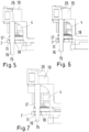
- Fig. 5
- eine Fixiereinrichtung in Fixierstellung,
- Fig. 6
- die Fixiereinrichtung beim Lösen und
- Fig. 7
- die Fixiereinrichtung in gelöster Position.
-
Fig. 1 zeigt schematisch einen Beschickungswagen 1 für ein nicht näher dargestelltes Behälterstapellager. - Der Beschickungswagen 1 weist ein Fahrgestell 2 mit mehreren Rädern 3 auf, mit denen der Beschickungswagen auf einem Fußboden oder einer anderen Unterlage verfahrbar ist.
- Ferner weist der Beschickungswagen 1 eine höhenverstellbare Behälteraufnahme 4 auf, deren Höhe gegenüber dem Fahrgestell 2 durch eine Hubeinrichtung 5 veränderbar ist. Die Hubeinrichtung 5 weist eine Schubkette auf, mit der die Behälteraufnahme 4 in eine Hubrichtung bewegt werden kann. Die Hubrichtung entspricht dabei in der Regel der Schwerkraftrichtung.
- Die Behälteraufnahme 4 weist eine Behälteraufstandsfläche 6 auf, auf der ein nicht näher dargestellter Behälter aufgesetzt werden kann. Die Schubkette wird durch einen Elektromotor oder einen anderen Aktor, der hydraulisch oder pneumatisch ausgebildet sein kann, angetrieben. Die Schubkette bildet damit einen Teil eines Hubantriebs.
- Die Behälteraufnahme 4 ist auf einer Grundplatte 7 angeordnet, die in
Fig. 3 näher dargestellt ist. Die Grundplatte 7 weist mehrere Kugelrollenanordnungen 8 auf. Jede Kugelrollenanordnung 8 weist eine Kugel 9 auf, die in einem Käfig 10 gehalten ist, der an der Grundplatte 7 befestigt ist. - Neben jeder Kugelrollenanordnung 8 ist eine Bohrung 11 angeordnet, die einen Teil einer Fixiereinrichtung bildet, die weiter unten beschrieben werden wird.
- Die Grundplatte 7 weist Führungselemente 12 auf, mit denen sie in entsprechenden Führungen 13 geführt ist, die am Fahrgestell 2 befestigt sind. Die Führungen 13 sind dabei an vertikal verlaufenden Streben 14 angeordnet.
-
Fig. 1 zeigt eine Ausgestaltung, bei der an allen vier Ecken der Grundplatte 7 entsprechende Führungen 12 vorgesehen sind. DieFig. 2 und 3 zeigen eine abgewandelte Ausgestaltung, um zu zeigen, dass prinzipiell nur zwei Führungen 12 erforderlich sind, die vorzugsweise an diagonal gegenüberliegenden Ecken der Grundplatte 7 angeordnet sind. - Die Behälteraufnahme 4 ruht auf den Kugelrollenanordnungen 8. Die Kugelrollenanordnungen 8 bilden dabei eine Lagereinrichtung, die eine Bewegung der Behälteraufnahme 4 gegenüber dem Fahrgestell 2 quer zur Hubrichtung ermöglicht.
- Eine derartige Bewegung kann jedoch durch die oben bereits erwähnte Fixiereinrichtung blockiert werden. Die Fixiereinrichtung ist lösbar, um die Bewegung der Behälteraufnahme 4 gegenüber der Grundplatte 7 und damit gegenüber dem Fahrgestell 2 zu ermöglichen. Hierzu weist die Fixiereinrichtung eine Stiftanordnung mit mindestens einem Stift 15 auf. Im vorliegenden Ausführungsbeispiel sind jedoch an allen Ecken der Behälteraufnahme 4 entsprechende Stifte 15 vorgesehen. Jeder Stift 15 tritt in die oben erwähnte Bohrung 11 ein.
- Wie man in
Fig. 5 erkennen kann, weist jeder Stift 15 einen ersten Abschnitt 16 mit einem ersten Durchmesser auf, der kleiner ist als ein Durchmesser der Bohrung 11, beispielsweise 10 mm bis 30 mm kleiner. Ferner weist jeder Stift 15 einen zweiten Abschnitt 17 auf, der einen zweiten Durchmesser aufweist, der dem Durchmesser der Bohrung 11 entspricht. Der zweite Abschnitt 17 weist gegenüber der Bohrung 11 ein kleines Spiel auf, d.h. der zweite Durchmesser ist geringfügig kleiner als der Durchmesser der Bohrung 11. Das Spiel ist jedoch nur so groß, dass eine Bewegung des Stifts 15 in der Bohrung 11 ermöglicht ist. Zwischen dem ersten Abschnitt 16 und dem zweiten Abschnitt 17 ist ein Übergangsabschnitt 18 vorgesehen, in dem sich der Durchmesser des Stifts 15 vom ersten Durchmesser zum zweiten Durchmesser hin erweitert. - Die Behälteraufnahme 4 weist eine Entriegelungseinrichtung auf, die an den vier Ecken der Behälteraufnahme jeweils ein Entriegelungselement 19-22 aufweist. Die Entriegelungselemente 19-22 sind an einer Rahmenanordnung mit zwei Rahmen 23, 24 befestigt.
- Die Rahmen 23, 24 sind mit einem zweiten Hubantrieb 25 verbunden, mit dem die Rahmen 23, 24 und damit die Entriegelungselemente 19-22 gegenüber der Behälteraufnahme 4 und damit gegenüber der Grundplatte 7 angehoben und abgesenkt werden können.
- Wenn die Entriegelungselemente 19-22 angehoben werden, dann können sie nicht näher dargestellte Halteelemente eines Behälterstapellagers öffnen und/oder in einer geöffneten Stellung halten, bis ein zu entnehmender Behälter mit der Behälteraufnahme 4 abgesenkt worden ist. Die Stifte 15 stehen mit dem Rahmen 23 in Verbindung und werden bei einem Anheben der Entriegelungselemente 19-22 ebenfalls mit angehoben. Dadurch gelangen die Stifte 15 aus der in
Fig. 5 dargestellten Position, in der die Behälteraufnahme 4 gegenüber der Grundplatte 7 quer zur Hubrichtung fixiert ist, in die inFig. 7 dargestellte Position, in der die Behälteraufnahme 4 gegenüber der Grundplatte 7 schwimmend gelagert ist. - In dieser Position ist eine Bewegung der Behälteraufnahme 4 gegenüber der Grundplatte 7 quer zur Hubrichtung möglich und zwar in der Größenordnung von einigen Zentimetern, beispielsweise 1 bis 3 cm.
- Die Entriegelungselemente 19-22 weisen eine Zentrierflächenanordnung auf. Die Zentrierflächenanordnung weist eine Fläche 26 auf, die gegenüber der Hubrichtung geneigt ist. Wenn die Behälteraufnahme 4 von unten an einen Behälter heranbewegt wird, beispielsweise in einem Einlager- oder Auslagerpunkt, dann sind zuvor die Entriegelungselemente 19-22 von der Grundplatte 7 wegbewegt worden und die Entriegelungselemente 19-22 kommen mit der geneigten Fläche 26 in Kontakt mit dem Behälter. Damit ist es möglich, die Behälteraufnahme 4 auf den Behälter auszurichten.
- Wie man in
Fig. 2 erkennen kann, weist die Behälteraufnahme an ihren Rändern Randleisten 27-30 auf, die verhindern, dass ein auf der Behälteraufnahme 4 ruhender Behälter beim Transport aus dem Stapellager hinaus oder in das Stapellager hinein von der Behälteraufnahme 4 herunterrutschen kann. -
Fig. 6 zeigt die Situation beim Absenken der Entriegelungselemente 19-22. Der Stift 15 wird durch den Übergangsbereich 18 in der Bohrung 11 zentriert, so dass die Behälteraufnahme 4 gegenüber der Grundplatte 7 wieder eine definierte Position erhält. - Die Behälteraufnahme 4 weist noch Ausklinkungen 31, 32 auf, wobei die Öffnung der Ausklinkungen 31, 32 vorzugsweise in Rollrichtung der Räder 3 gerichtet ist. Damit ist es möglich, einen Behälter, der auf der Behälteraufnahme 4 steht, in eine Abgabestation zu übergeben, wobei es lediglich erforderlich ist, dass die Abgabestation zwei zinkenartige Vorsprünge aufweist, die in die Ausklinkungen 31, 32 eintreten können, wenn der Beschickungswagen 1 entsprechend dorthin verfahren wird. Danach kann die Behälteraufnahme 4 abgesenkt werden, so dass der Behälter an die Abgabestation übergeben werden kann. Auch die Übernahme eines Behälters aus einer entsprechenden Aufnahmeeinrichtung kann auf diese Weise realisiert werden. Hierzu wird der Beschickungswagen 1 ohne Behälter in die Aufnahmeeinrichtung gefahren. Wenn dann die Hubeinrichtung 5 die Behälteraufnahme 4 anhebt, kommt der Behälter von der Aufnahmeeinrichtung frei und kann dann gemeinsam mit dem Beschickungswagen 1 abtransportiert werden.
Claims (10)
- Behälterstapellager-Beschickungswagen (1) mit einem Fahrgestell (2) und einer gegenüber dem Fahrgestell (2) höhenverstellbaren Behälteraufnahme (4), die einen Aufnahmebereich mit einer Behälteraufstandsfläche (6) aufweist, wobei zwischen dem Fahrgestell (2) und der Behälteraufnahme (4) eine in eine Hubrichtung wirkende Hubeinrichtung (5) angeordnet ist, wobei zwischen der Behälteraufnahme (4) und dem Fahrgestell (2) eine Lagereinrichtung (8) angeordnet ist, die die Behälteraufnahme schwimmend lagert und eine Bewegung der Behälteraufnahme (4) gegenüber dem Fahrgestell (2) quer zur Hubrichtung ermöglicht, wobei eine Fixiereinrichtung (11, 15, 25) vorgesehen ist, die die Behälteraufnahme bei einem Transport eines Behälters aus einem Behälterstapellager (4) gegenüber dem Fahrgestell (2) quer zur Hubrichtung fixiert, wobei die Fixiereinrichtung (11, 15, 25) lösbar ist, um die schwimmende Lagerung zu ermöglichen.
- Beschickungswagen nach Anspruch 1, dadurch gekennzeichnet, dass die Fixiereinrichtung (11, 15, 25) eine Stiftanordnung mit mindestens einem parallel zur Hubrichtung verlaufenden Stift (15) aufweist, der in einer quer zur Hubrichtung ortsfesten Bohrung (11) angeordnet ist, wobei der Stift (15) einen ersten Abschnitt (16) mit einem ersten Durchmesser, der kleiner ist als ein Durchmesser der Bohrung (11), und einen zweiten Abschnitt (17) mit einem zweiten Durchmesser aufweist, der dem Durchmesser der Bohrung (11) entspricht, wobei zwischen dem ersten Abschnitt (16) und dem zweiten Abschnitt (17) ein Übergangsabschnitt (18) vorgesehen ist, in dem sich der Durchmesser des Stiftes (15) vom ersten Durchmesser zum zweiten Durchmesser vergrößert.
- Beschickungswagen nach Anspruch 1 oder 2, dadurch gekennzeichnet, dass die Hubeinrichtung (5) einen ersten Hubantrieb aufweist und ein zweiter Hubantrieb (25) vorgesehen ist, der auf eine Entriegelungseinrichtung für Halteelemente eines Behälterstapellagers wirkt, wobei der zweite Hubantrieb (25) einen Teil der Fixiereinrichtung (11, 15, 25) bildet.
- Beschickungswagen nach Anspruch 3, dadurch gekennzeichnet, dass die Entriegelungselementanordnung mehrere im Bereich von Ecken der Behälteraufnahme (4) angeordnete Entriegelungselemente (19-22) aufweist, wobei zumindest einige der Entriegelungselemente (19-22) eine Zentrierflächenanordnung (26) aufweisen, die zum Aufnahmebereich gerichtet ist.
- Beschickungswagen nach Anspruch 4, dadurch gekennzeichnet, dass die Entriegelungselementanordnung mit der Stiftanordnung in Wirkverbindung steht.
- Beschickungswagen nach Anspruch 4 oder 5, dadurch gekennzeichnet, dass die Zentrierflächenanordnung (26) gegenüber der Hubrichtung geneigt ist.
- Beschickungswagen nach einem der Ansprüche 4 bis 6, dadurch gekennzeichnet, dass die Entriegelungselementanordnung in einer Transportposition der Behälteraufnahme (4) über die Behälteraufstandsfläche (6) im Aufnahmebereich vorsteht.
- Beschickungswagen nach einem der Ansprüche 4 bis 7, dadurch gekennzeichnet, dass die Behälteraufnahme (4) Randleisten (27-30) aufweist, die die Behälteraufstandsfläche (6) begrenzen.
- Beschickungswagen nach einem der Ansprüche 1 bis 8,
dadurch gekennzeichnet,
dass die Behälteraufnahme (4) auf einer Grundplatte (7) gelagert ist, mit der die Hubeinrichtung (5) zusammenwirkt. - Beschickungswagen nach Anspruch 9, dadurch gekennzeichnet, dass zwischen der Grundplatte (7) und der Behälteraufnahme (4) eine Kugelrollenanordnung (8) angeordnet ist.
Priority Applications (5)
| Application Number | Priority Date | Filing Date | Title |
|---|---|---|---|
| EP19193382.9A EP3782933B1 (de) | 2019-08-23 | 2019-08-23 | Behälterstapellager-beschickungswagen |
| ES19193382T ES2946045T3 (es) | 2019-08-23 | 2019-08-23 | Carro de abastecimiento de almacén de pilas de contenedores |
| PL19193382.9T PL3782933T3 (pl) | 2019-08-23 | 2019-08-23 | Wózek załadowczy do układania pojemników w stosy w magazynie piętrowym |
| CN202010611985.7A CN112407711B (zh) | 2019-08-23 | 2020-06-30 | 容器堆垛仓装载车 |
| US16/998,602 US11230446B2 (en) | 2019-08-23 | 2020-08-20 | Container stacking storage system loading trolley |
Applications Claiming Priority (1)
| Application Number | Priority Date | Filing Date | Title |
|---|---|---|---|
| EP19193382.9A EP3782933B1 (de) | 2019-08-23 | 2019-08-23 | Behälterstapellager-beschickungswagen |
Publications (2)
| Publication Number | Publication Date |
|---|---|
| EP3782933A1 EP3782933A1 (de) | 2021-02-24 |
| EP3782933B1 true EP3782933B1 (de) | 2023-03-15 |
Family
ID=67742278
Family Applications (1)
| Application Number | Title | Priority Date | Filing Date |
|---|---|---|---|
| EP19193382.9A Active EP3782933B1 (de) | 2019-08-23 | 2019-08-23 | Behälterstapellager-beschickungswagen |
Country Status (5)
| Country | Link |
|---|---|
| US (1) | US11230446B2 (de) |
| EP (1) | EP3782933B1 (de) |
| CN (1) | CN112407711B (de) |
| ES (1) | ES2946045T3 (de) |
| PL (1) | PL3782933T3 (de) |
Families Citing this family (2)
| Publication number | Priority date | Publication date | Assignee | Title |
|---|---|---|---|---|
| EP3838802A1 (de) * | 2019-12-19 | 2021-06-23 | Jungheinrich Aktiengesellschaft | Stapellageranordnung und verfahren zum betreiben einer stapellageranordnung |
| EP3960657B1 (de) * | 2020-08-26 | 2024-03-27 | Jungheinrich Aktiengesellschaft | Stapellageranordnung |
Family Cites Families (13)
| Publication number | Priority date | Publication date | Assignee | Title |
|---|---|---|---|---|
| KR910007253B1 (ko) * | 1986-10-04 | 1991-09-24 | 닛또 고오기 가부시기가이샤 | 팔렛트 첸저(Pallet Changer) |
| DE19849391C2 (de) | 1998-10-27 | 2002-02-14 | Josef Basic | Kistenstapellager |
| DE19855927A1 (de) * | 1998-12-04 | 2000-06-15 | Helmut Unterberg | Werkstückwechselsystem für Bearbeitungszentren |
| US7152882B2 (en) * | 2002-03-28 | 2006-12-26 | Sanyo Electric Co., Ltd. | Mobile carriage |
| DE102010026885A1 (de) * | 2010-07-07 | 2012-01-12 | Jungheinrich Aktiengesellschaft | Wagen zum Transport von Paletten innerhalb eines Tiefen-Regalsystems |
| US8851488B2 (en) * | 2012-06-15 | 2014-10-07 | Iscar Gse Corp. | Modular cargo dolly |
| HU230618B1 (hu) * | 2014-04-07 | 2017-04-28 | Antal Zombori | Raktári árukezelő rendszer és rakodó-berendezés raktári árukezelő rendszerhez |
| US9890025B2 (en) * | 2015-11-24 | 2018-02-13 | Amazon Technologies, Inc. | Mechanical tipping assembly for mobile drive unit of inventory system |
| CN105731295A (zh) * | 2016-04-14 | 2016-07-06 | 上海诺力智能科技有限公司 | 一种具有独立顶升结构的可旋转潜入式自动导引车 |
| US10289117B1 (en) * | 2017-02-21 | 2019-05-14 | Amazon Technologies, Inc. | Lift and tilt platform |
| CN109501745A (zh) * | 2017-10-30 | 2019-03-22 | 蔚来汽车有限公司 | 换电运输器 |
| CN108128587B (zh) * | 2018-02-12 | 2023-09-01 | 杭州海康机器人股份有限公司 | 一种搬运设备的多层运行系统 |
| CN109573443B (zh) * | 2019-01-15 | 2024-02-23 | 杭州大氚智能科技有限公司 | 一种仓储分拣系统 |
-
2019
- 2019-08-23 ES ES19193382T patent/ES2946045T3/es active Active
- 2019-08-23 EP EP19193382.9A patent/EP3782933B1/de active Active
- 2019-08-23 PL PL19193382.9T patent/PL3782933T3/pl unknown
-
2020
- 2020-06-30 CN CN202010611985.7A patent/CN112407711B/zh active Active
- 2020-08-20 US US16/998,602 patent/US11230446B2/en active Active
Also Published As
| Publication number | Publication date |
|---|---|
| ES2946045T3 (es) | 2023-07-12 |
| CN112407711B (zh) | 2022-10-04 |
| EP3782933A1 (de) | 2021-02-24 |
| US11230446B2 (en) | 2022-01-25 |
| PL3782933T3 (pl) | 2023-09-18 |
| CN112407711A (zh) | 2021-02-26 |
| US20210053778A1 (en) | 2021-02-25 |
Similar Documents
| Publication | Publication Date | Title |
|---|---|---|
| DE102013009340B4 (de) | Einrichtung und Verfahren zum Ein- und Auslagern von stapelbaren Behältern | |
| DE102007040863B4 (de) | Lagerregal mit Transportvorrichtung | |
| EP2353778A2 (de) | Regalmagazin | |
| WO2012025290A1 (de) | Lagerregalsystem zur lagerung von lagergut | |
| EP3782933B1 (de) | Behälterstapellager-beschickungswagen | |
| DE19513179C2 (de) | Lagerregal | |
| EP3782929A1 (de) | Behälterstapellager-beschickungswagen | |
| EP0589844A1 (de) | Hochleistungs-Blocklager mit Mitteln zum Ein- und Auslagern von Lagergut | |
| EP2746193B1 (de) | Regalfahrzeug, Regalbediengerät, Lager und entsprechendes Verfahren | |
| EP3960657B1 (de) | Stapellageranordnung | |
| EP3782932B1 (de) | Stapellageranordnung | |
| EP3609835A1 (de) | Flurförderzeug mit schubeinrichtung | |
| EP2033735B1 (de) | Kompakter Werkstückwechsler | |
| EP1140671A1 (de) | Verfahren zum ein- und/oder auslagern von lagergütern, lagervorrichtung und lagergutträger | |
| DE102017116176A1 (de) | Tasten-Bearbeitung und -Montage mittels Trays | |
| EP3251987A1 (de) | Beladesystem für stückgüter mit transportierbarer beladevorrichtung | |
| DE102008034431A1 (de) | Batteriewagen zur Aufnahme eines Batterietrogs für ein Flurförderzeug | |
| DE202022101942U1 (de) | Shuttleaufzug für Regalsystem und Regalsystem | |
| DE102013102994A1 (de) | Lager und lagerbediengeräte mit passierfunktion | |
| WO2023198452A1 (de) | Shuttleaufzug für regalsystem, regalsystem und verfahren zum verlagern eines shuttles | |
| DE102012112828A1 (de) | Lager und Lagerbediengeräte mit Passierfunktion | |
| WO2021224154A1 (de) | Shuttle und regalsystem | |
| DE102022108761A1 (de) | Shuttleaufzug für Regalsystem, Regalsystem und Verfahren zum Verlagern eines Shuttles | |
| DE102015001543A1 (de) | Vorrichtung zur Handhabung von Ladungsträgern und Verfahren zum Betrieb einer solchen Vorrichtung | |
| WO2022043278A1 (de) | Aufzug und regalsystem |
Legal Events
| Date | Code | Title | Description |
|---|---|---|---|
| PUAI | Public reference made under article 153(3) epc to a published international application that has entered the european phase |
Free format text: ORIGINAL CODE: 0009012 |
|
| STAA | Information on the status of an ep patent application or granted ep patent |
Free format text: STATUS: REQUEST FOR EXAMINATION WAS MADE |
|
| 17P | Request for examination filed |
Effective date: 20200508 |
|
| AK | Designated contracting states |
Kind code of ref document: A1 Designated state(s): AL AT BE BG CH CY CZ DE DK EE ES FI FR GB GR HR HU IE IS IT LI LT LU LV MC MK MT NL NO PL PT RO RS SE SI SK SM TR |
|
| AX | Request for extension of the european patent |
Extension state: BA ME |
|
| GRAP | Despatch of communication of intention to grant a patent |
Free format text: ORIGINAL CODE: EPIDOSNIGR1 |
|
| STAA | Information on the status of an ep patent application or granted ep patent |
Free format text: STATUS: GRANT OF PATENT IS INTENDED |
|
| RIC1 | Information provided on ipc code assigned before grant |
Ipc: B66F 9/06 20060101ALN20220615BHEP Ipc: B65G 57/30 20060101ALI20220615BHEP Ipc: B65G 1/04 20060101AFI20220615BHEP |
|
| RIC1 | Information provided on ipc code assigned before grant |
Ipc: B66F 9/06 20060101ALN20220624BHEP Ipc: B65G 57/30 20060101ALI20220624BHEP Ipc: B65G 1/04 20060101AFI20220624BHEP |
|
| INTG | Intention to grant announced |
Effective date: 20220714 |
|
| GRAJ | Information related to disapproval of communication of intention to grant by the applicant or resumption of examination proceedings by the epo deleted |
Free format text: ORIGINAL CODE: EPIDOSDIGR1 |
|
| STAA | Information on the status of an ep patent application or granted ep patent |
Free format text: STATUS: REQUEST FOR EXAMINATION WAS MADE |
|
| INTC | Intention to grant announced (deleted) | ||
| GRAP | Despatch of communication of intention to grant a patent |
Free format text: ORIGINAL CODE: EPIDOSNIGR1 |
|
| STAA | Information on the status of an ep patent application or granted ep patent |
Free format text: STATUS: GRANT OF PATENT IS INTENDED |
|
| RIC1 | Information provided on ipc code assigned before grant |
Ipc: B66F 9/06 20060101ALN20221123BHEP Ipc: B65G 57/30 20060101ALI20221123BHEP Ipc: B65G 1/04 20060101AFI20221123BHEP |
|
| INTG | Intention to grant announced |
Effective date: 20221213 |
|
| GRAS | Grant fee paid |
Free format text: ORIGINAL CODE: EPIDOSNIGR3 |
|
| GRAA | (expected) grant |
Free format text: ORIGINAL CODE: 0009210 |
|
| STAA | Information on the status of an ep patent application or granted ep patent |
Free format text: STATUS: THE PATENT HAS BEEN GRANTED |
|
| AK | Designated contracting states |
Kind code of ref document: B1 Designated state(s): AL AT BE BG CH CY CZ DE DK EE ES FI FR GB GR HR HU IE IS IT LI LT LU LV MC MK MT NL NO PL PT RO RS SE SI SK SM TR |
|
| REG | Reference to a national code |
Ref country code: CH Ref legal event code: EP Ref country code: GB Ref legal event code: FG4D Free format text: NOT ENGLISH |
|
| REG | Reference to a national code |
Ref country code: DE Ref legal event code: R096 Ref document number: 502019007201 Country of ref document: DE |
|
| REG | Reference to a national code |
Ref country code: IE Ref legal event code: FG4D Free format text: LANGUAGE OF EP DOCUMENT: GERMAN |
|
| REG | Reference to a national code |
Ref country code: AT Ref legal event code: REF Ref document number: 1553902 Country of ref document: AT Kind code of ref document: T Effective date: 20230415 |
|
| REG | Reference to a national code |
Ref country code: NL Ref legal event code: FP |
|
| REG | Reference to a national code |
Ref country code: NO Ref legal event code: T2 Effective date: 20230315 Ref country code: LT Ref legal event code: MG9D |
|
| REG | Reference to a national code |
Ref country code: ES Ref legal event code: FG2A Ref document number: 2946045 Country of ref document: ES Kind code of ref document: T3 Effective date: 20230712 |
|
| PG25 | Lapsed in a contracting state [announced via postgrant information from national office to epo] |
Ref country code: RS Free format text: LAPSE BECAUSE OF FAILURE TO SUBMIT A TRANSLATION OF THE DESCRIPTION OR TO PAY THE FEE WITHIN THE PRESCRIBED TIME-LIMIT Effective date: 20230315 Ref country code: LV Free format text: LAPSE BECAUSE OF FAILURE TO SUBMIT A TRANSLATION OF THE DESCRIPTION OR TO PAY THE FEE WITHIN THE PRESCRIBED TIME-LIMIT Effective date: 20230315 Ref country code: LT Free format text: LAPSE BECAUSE OF FAILURE TO SUBMIT A TRANSLATION OF THE DESCRIPTION OR TO PAY THE FEE WITHIN THE PRESCRIBED TIME-LIMIT Effective date: 20230315 Ref country code: HR Free format text: LAPSE BECAUSE OF FAILURE TO SUBMIT A TRANSLATION OF THE DESCRIPTION OR TO PAY THE FEE WITHIN THE PRESCRIBED TIME-LIMIT Effective date: 20230315 |
|
| P01 | Opt-out of the competence of the unified patent court (upc) registered |
Effective date: 20230628 |
|
| PG25 | Lapsed in a contracting state [announced via postgrant information from national office to epo] |
Ref country code: SE Free format text: LAPSE BECAUSE OF FAILURE TO SUBMIT A TRANSLATION OF THE DESCRIPTION OR TO PAY THE FEE WITHIN THE PRESCRIBED TIME-LIMIT Effective date: 20230315 Ref country code: GR Free format text: LAPSE BECAUSE OF FAILURE TO SUBMIT A TRANSLATION OF THE DESCRIPTION OR TO PAY THE FEE WITHIN THE PRESCRIBED TIME-LIMIT Effective date: 20230616 Ref country code: FI Free format text: LAPSE BECAUSE OF FAILURE TO SUBMIT A TRANSLATION OF THE DESCRIPTION OR TO PAY THE FEE WITHIN THE PRESCRIBED TIME-LIMIT Effective date: 20230315 |
|
| PGFP | Annual fee paid to national office [announced via postgrant information from national office to epo] |
Ref country code: NL Payment date: 20230823 Year of fee payment: 5 |
|
| PG25 | Lapsed in a contracting state [announced via postgrant information from national office to epo] |
Ref country code: SM Free format text: LAPSE BECAUSE OF FAILURE TO SUBMIT A TRANSLATION OF THE DESCRIPTION OR TO PAY THE FEE WITHIN THE PRESCRIBED TIME-LIMIT Effective date: 20230315 Ref country code: RO Free format text: LAPSE BECAUSE OF FAILURE TO SUBMIT A TRANSLATION OF THE DESCRIPTION OR TO PAY THE FEE WITHIN THE PRESCRIBED TIME-LIMIT Effective date: 20230315 Ref country code: PT Free format text: LAPSE BECAUSE OF FAILURE TO SUBMIT A TRANSLATION OF THE DESCRIPTION OR TO PAY THE FEE WITHIN THE PRESCRIBED TIME-LIMIT Effective date: 20230717 Ref country code: EE Free format text: LAPSE BECAUSE OF FAILURE TO SUBMIT A TRANSLATION OF THE DESCRIPTION OR TO PAY THE FEE WITHIN THE PRESCRIBED TIME-LIMIT Effective date: 20230315 |
|
| PGFP | Annual fee paid to national office [announced via postgrant information from national office to epo] |
Ref country code: NO Payment date: 20230822 Year of fee payment: 5 Ref country code: IT Payment date: 20230831 Year of fee payment: 5 Ref country code: GB Payment date: 20230824 Year of fee payment: 5 Ref country code: ES Payment date: 20230918 Year of fee payment: 5 Ref country code: CZ Payment date: 20230814 Year of fee payment: 5 Ref country code: CH Payment date: 20230902 Year of fee payment: 5 |
|
| PG25 | Lapsed in a contracting state [announced via postgrant information from national office to epo] |
Ref country code: SK Free format text: LAPSE BECAUSE OF FAILURE TO SUBMIT A TRANSLATION OF THE DESCRIPTION OR TO PAY THE FEE WITHIN THE PRESCRIBED TIME-LIMIT Effective date: 20230315 Ref country code: IS Free format text: LAPSE BECAUSE OF FAILURE TO SUBMIT A TRANSLATION OF THE DESCRIPTION OR TO PAY THE FEE WITHIN THE PRESCRIBED TIME-LIMIT Effective date: 20230715 |
|
| PGFP | Annual fee paid to national office [announced via postgrant information from national office to epo] |
Ref country code: PL Payment date: 20230814 Year of fee payment: 5 Ref country code: FR Payment date: 20230821 Year of fee payment: 5 Ref country code: DE Payment date: 20230822 Year of fee payment: 5 |
|
| REG | Reference to a national code |
Ref country code: DE Ref legal event code: R097 Ref document number: 502019007201 Country of ref document: DE |
|
| PLBE | No opposition filed within time limit |
Free format text: ORIGINAL CODE: 0009261 |
|
| STAA | Information on the status of an ep patent application or granted ep patent |
Free format text: STATUS: NO OPPOSITION FILED WITHIN TIME LIMIT |
|
| PG25 | Lapsed in a contracting state [announced via postgrant information from national office to epo] |
Ref country code: SI Free format text: LAPSE BECAUSE OF FAILURE TO SUBMIT A TRANSLATION OF THE DESCRIPTION OR TO PAY THE FEE WITHIN THE PRESCRIBED TIME-LIMIT Effective date: 20230315 Ref country code: DK Free format text: LAPSE BECAUSE OF FAILURE TO SUBMIT A TRANSLATION OF THE DESCRIPTION OR TO PAY THE FEE WITHIN THE PRESCRIBED TIME-LIMIT Effective date: 20230315 |
|
| 26N | No opposition filed |
Effective date: 20231218 |
|
| PG25 | Lapsed in a contracting state [announced via postgrant information from national office to epo] |
Ref country code: MC Free format text: LAPSE BECAUSE OF FAILURE TO SUBMIT A TRANSLATION OF THE DESCRIPTION OR TO PAY THE FEE WITHIN THE PRESCRIBED TIME-LIMIT Effective date: 20230315 |
|
| PG25 | Lapsed in a contracting state [announced via postgrant information from national office to epo] |
Ref country code: MC Free format text: LAPSE BECAUSE OF FAILURE TO SUBMIT A TRANSLATION OF THE DESCRIPTION OR TO PAY THE FEE WITHIN THE PRESCRIBED TIME-LIMIT Effective date: 20230315 |