EP3781461B1 - Structure de caisse de vehicule automobile avec renfort de traverse d'assise arrière - Google Patents
Structure de caisse de vehicule automobile avec renfort de traverse d'assise arrière Download PDFInfo
- Publication number
- EP3781461B1 EP3781461B1 EP19715157.4A EP19715157A EP3781461B1 EP 3781461 B1 EP3781461 B1 EP 3781461B1 EP 19715157 A EP19715157 A EP 19715157A EP 3781461 B1 EP3781461 B1 EP 3781461B1
- Authority
- EP
- European Patent Office
- Prior art keywords
- arm
- floor
- cross
- rear seat
- load floor
- Prior art date
- Legal status (The legal status is an assumption and is not a legal conclusion. Google has not performed a legal analysis and makes no representation as to the accuracy of the status listed.)
- Active
Links
- 230000002787 reinforcement Effects 0.000 title description 8
Images
Classifications
-
- B—PERFORMING OPERATIONS; TRANSPORTING
- B62—LAND VEHICLES FOR TRAVELLING OTHERWISE THAN ON RAILS
- B62D—MOTOR VEHICLES; TRAILERS
- B62D25/00—Superstructure or monocoque structure sub-units; Parts or details thereof not otherwise provided for
- B62D25/20—Floors or bottom sub-units
- B62D25/2009—Floors or bottom sub-units in connection with other superstructure subunits
- B62D25/2027—Floors or bottom sub-units in connection with other superstructure subunits the subunits being rear structures
-
- B—PERFORMING OPERATIONS; TRANSPORTING
- B62—LAND VEHICLES FOR TRAVELLING OTHERWISE THAN ON RAILS
- B62D—MOTOR VEHICLES; TRAILERS
- B62D21/00—Understructures, i.e. chassis frame on which a vehicle body may be mounted
- B62D21/15—Understructures, i.e. chassis frame on which a vehicle body may be mounted having impact absorbing means, e.g. a frame designed to permanently or temporarily change shape or dimension upon impact with another body
- B62D21/152—Front or rear frames
-
- B—PERFORMING OPERATIONS; TRANSPORTING
- B62—LAND VEHICLES FOR TRAVELLING OTHERWISE THAN ON RAILS
- B62D—MOTOR VEHICLES; TRAILERS
- B62D25/00—Superstructure or monocoque structure sub-units; Parts or details thereof not otherwise provided for
- B62D25/08—Front or rear portions
-
- B—PERFORMING OPERATIONS; TRANSPORTING
- B62—LAND VEHICLES FOR TRAVELLING OTHERWISE THAN ON RAILS
- B62D—MOTOR VEHICLES; TRAILERS
- B62D43/00—Spare wheel stowing, holding, or mounting arrangements
- B62D43/06—Spare wheel stowing, holding, or mounting arrangements within the vehicle body
- B62D43/10—Spare wheel stowing, holding, or mounting arrangements within the vehicle body and arranged substantially horizontally
Definitions
- the invention relates to the field of motor vehicles, more particularly to motor vehicle bodies.
- the published patent document FR 3 007 377 A1 discloses a motor vehicle body structure comprising a rear seat cushion front floor and a rear load floor. Reinforcements of the rear seat cushion floor are arranged on an underside of said floor. The reinforcements are in the form of plates. The reinforcements extend, in a flared manner, from the middle of a front edge of the rear seat cushion floor, towards a lower side edge of the seat cushion floor. These reinforcements are intended to improve the behavior of the vehicle in the event of a rear impact.
- the structure of the motor vehicle of this state of the art makes the motor vehicle heavier. It thus fails to lighten the structure of the motor vehicle while satisfactorily ensuring reinforcement of the structure in the event of a rear impact, in particular at the level of the rear seat.
- the object of the invention is to overcome at least one of the drawbacks of the aforementioned state of the art. More particularly, the object of the invention is to propose a solution making it possible to lighten the body structure of a motor vehicle and to reinforce said structure in the event of a rear impact, in particular at the level of the rear seat. The invention also aims at a simple, robust and economical solution.
- front and rear are related to the normal direction of travel of a motor vehicle.
- the subject of the invention is a motor vehicle body structure comprising a rear load floor; a rear seat base cross member, located at the front of the rear load floor; remarkable in that the rear seat base cross member is at a distance from the rear load floor; and the structure further comprises an arm extending longitudinally and connecting said floor to said crosspiece.
- the rear seat base cross member is at a height lower than that of a front edge of the rear load floor, the arm having a front end inclined downwards and forwards, fixed to said cross member , so as to compensate for the difference in height.
- the arm forms a U-section beam fixed to the underside of the rear load floor.
- the arm extends centrally longitudinally.
- the rear load floor forms a bowl, in particular for storing a spare wheel, the arm having a non-rectilinear profile matching a front portion of said bowl.
- the arm comprises a first portion matching the front portion of the bowl of the rear load floor, and a second portion matching a generally planar portion of said floor located at the front of said front portion of the bowl .
- the arm comprises a rear end forming a lug fixed to a bottom of the bowl of the rear load floor.
- the rear seat base cross member is a U-shaped or V-shaped section profile forming an opening directed upwards and forwards and comprising a front wing and a rear wing , the arm being connected to an upper edge of said rear wing.
- the rear seat base cross member comprises at least two bridges each extending in the U- or V-section of said cross-member, between the front and rear fenders, so as to form mounting surfaces of the rear seat(s).
- the rear seat base cross member comprises two ends fixed to two interior side rails.
- the measures of the invention are advantageous in that the body structure has a mass saving compared to the state of the art while ensuring a reinforcement of the vehicle in the event of an impact, more particularly in the event of a rear impact.
- the seat cross member located at a distance from the rear floor allows a gain in mass and a more dynamic structure compared to the state of the art.
- the invention also provides effective reinforcement of the structure and more particularly at the level of the seat cross member, in the event of a rear impact, by means of an arm extending longitudinally and connecting the rear floor to said cross member.
- the non-rectilinear profile of the arm limits the tensile and rotational forces on said arm, in the event of an impact.
- the arm is fixed to a spare wheel storage cup in the rear floor and has a profile matching the shape of the cup, thus limiting the forces on the arm in the event of an impact.
- the invention also has the advantage of being simple to implement and inexpensive.
- the structure 2 of the motor vehicle body comprises a rear load floor 4 and a seat cross member 6 of the rear seat.
- the cross seat 6 is located in front of the rear floor 4 load.
- the cross seat 6 is located at a distance from the rear floor 4 load.
- the seat cross member 6 is at a distance from the rear floor 4 greater than 10 mm and/or less than 500 mm.
- the seat cross member 6 of the rear seat comprises two ends 8 fixed to two interior side rails 10.
- Fixing the seat cross member 6 at a distance from the rear floor 4 makes it possible to make the structure dynamic and save mass on the structure 2 of the motor vehicle.
- the structure further comprises an arm 12 extending longitudinally and connecting said rear floor 4 to the cross member of seat 6.
- the arm 12 forms a U-section beam fixed to the underside 14 of the rear load floor 4. Arm 12 extends centrally longitudinally.
- the seat cross member 6 of the rear seat is at a height lower than that of a front edge 16 of the rear floor 4 of the load.
- the arm 12 has a front end 17 inclined downwards and forwards, fixed to the seat cross member 6, so as to compensate for the difference in height between the seat cross member 6 and the front edge 16 of the rear floor of the charge.
- the height difference between the seat cross member 6 and the front edge 16 of the floor is greater than 10 mm and/or less than 200 mm.
- the seat cross member 6 of the rear seat is a U-shaped or V-shaped section profile forming an opening directed upwards and forwards and comprising a front wing 18 and a rear wing 20.
- the arm 12 is connected to an upper edge 22 of said rear fender 20. More particularly, the front end 17 of arm 12 is connected to said upper edge 22 of rear fender 20.
- the seat cross member 6 of the rear seat comprises at least two bridges 24 in the U- or V-section of said cross-member 6.
- the at least two bridges 24 each extend between the front 18 and rear 20 fenders, so as to form fixing surfaces 26 of the rear seat(s). Only two bridges 24 are shown.
- the rear load floor 4 forms a bowl 28, in particular for storing a spare wheel (not shown).
- the arm 12 has a non-rectilinear profile hugging a front portion 30 of said bowl 28. More particularly, the arm 12 comprises a first portion 32 hugging the front portion 30 of the bowl 28 of the rear load floor 4, and a second portion 34 marrying a generally planar portion 36 of said floor 4 located in front of said front portion 30 of bowl 28 ( figure 4 ).
- the arm 12 comprises a rear end 38 forming a tab 40 fixed to a bottom 42 of the bowl 28 of the rear floor 4 load.
- the non-rectilinear profile of the arm 12 makes it possible to limit the tensile and rotational forces on the arm 12 in the event of a rear impact on the structure of the vehicle.
Landscapes
- Engineering & Computer Science (AREA)
- Chemical & Material Sciences (AREA)
- Combustion & Propulsion (AREA)
- Transportation (AREA)
- Mechanical Engineering (AREA)
- Body Structure For Vehicles (AREA)
Description
- L'invention a trait au domaine des véhicules automobiles, plus particulièrement aux caisses de véhicule automobile.
- Le document de brevet publié
FR 3 007 377 A1 - En outre, le document
DE 10 2014 223054 A1 divulgue une structure conforme au préambule de la revendication 1. - L'invention a pour objectif de pallier au moins un des inconvénients de l'état de la technique susmentionné. Plus particulièrement, l'invention a pour objectif de proposer une solution permettant d'alléger la structure de caisse de véhicule automobile et de renforcer ladite structure en cas de choc arrière, notamment au niveau de l'assise arrière. L'invention a également pour objectif une solution simple, robuste et économique.
- Dans la suite, les termes « avant » et « arrière » sont en relation avec le sens de marche normal d'un véhicule automobile.
- L'invention a pour objet une structure de caisse de véhicule automobile comprenant un plancher arrière de charge ; une traverse d'assise de siège arrière, située à l'avant du plancher arrière de charge ; remarquable en ce que la traverse d'assise de siège arrière est à distance du plancher arrière de charge ; et la structure comprend, en outre, un bras s'étendant longitudinalement et reliant ledit plancher à ladite traverse.
- Selon l'invention, la traverse d'assise de siège arrière est à une hauteur inférieure à celle d'un bord avant du plancher arrière de charge, le bras présentant une extrémité avant inclinée vers le bas et l'avant, fixée à ladite traverse, de manière à compenser la différence de hauteur.
- Selon un mode avantageux de l'invention, le bras forme une poutre de section en U fixée sur la face inférieure du plancher arrière de charge.
- Selon un mode avantageux de l'invention, le bras s'étend longitudinalement de manière centrale.
- Selon un mode avantageux de l'invention, le plancher arrière de charge forme une cuvette, notamment pour le stockage d'une roue de rechange, le bras présentant un profil non-rectiligne épousant une portion avant de ladite cuvette.
- Selon un mode avantageux de l'invention, le bras comprend une première portion épousant la portion avant de la cuvette du plancher arrière de charge, et une deuxième portion épousant une portion généralement plane dudit plancher située à l'avant de ladite portion avant de cuvette.
- Selon un mode avantageux de l'invention, le bras comprend une extrémité arrière formant une patte fixée à un fond de la cuvette du plancher arrière de charge.
- Selon un mode avantageux de l'invention, la traverse d'assise de siège arrière est un profilé de section en forme de U ou de V formant une ouverture dirigée vers le haut et vers l'avant et comprenant une aile avant et une aile arrière, le bras étant relié à un bord supérieur de ladite aile arrière.
- Selon un mode avantageux de l'invention, la traverse d'assise de siège arrière comprend au moins deux pontets s'étendant chacun dans la section en U ou en V de ladite traverse, entre les ailes avant et arrière, de manière à former des surfaces de fixation du ou des sièges arrière.
- Selon un mode avantageux de l'invention, la traverse d'assise de siège arrière comprend deux extrémités fixées à deux longerons latéraux intérieurs.
- Les mesures de l'invention sont intéressantes en ce que la structure de caisse présente un gain de masse par rapport à l'état de l'art tout en assurant un renforcement du véhicule en cas de choc, plus particulièrement en cas de choc arrière. La traverse d'assise située à distance du plancher arrière permet un gain de masse et une structure plus dynamique par rapport à l'état de l'art. L'invention assure également un renforcement efficace de la structure et plus particulièrement au niveau de la traverse d'assise, en cas de choc arrière, au moyen d'un bras s'étendant longitudinalement et reliant le plancher arrière à ladite traverse. Ainsi, lors d'un choc arrière sur la structure du véhicule, les efforts sont transmis vers le plancher arrière du véhicule. Les efforts sur la traverse d'assise en cas de choc sont limités. Le profil non-rectiligne du bras limite les efforts de traction et de rotation sur ledit bras, en cas de choc. Dans un mode de réalisation, le bras est fixé à une cuvette de stockage de roue de rechange du plancher arrière et présente un profil épousant la forme de la cuvette, limitant ainsi les efforts sur le bras en cas de choc. L'invention présente également l'avantage d'être simple à mettre en oeuvre et peu coûteuse.
- D'autres caractéristiques et avantages de la présente invention seront mieux compris à l'aide de la description et des dessins parmi lesquels :
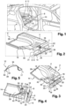
- La
figure 1 représente une caisse de véhicule automobile comprenant une structure conformément à l'invention ; - La
figure 2 représente une vue en perspective du plancher arrière et de la traverse d'assise arrière de la structure de caisse de véhicule automobile selon l'invention représentée à lafigure 1 ; - La
figure 3 représente une vue de dessus de la structure de caisse de véhicule automobile représentée à lafigure 2 ; - La
figure 4 représente une vue de dessous de la structure de caisse de véhicule automobile représentée auxfigures 2 et 3 ; - La
figure 5 représente une vue de profil du bras de la structure de caisse précédemment représentée auxfigures 2 à 4 . - Pour une meilleure compréhension de l'invention, les
figures 1 à 5 seront décrites ensemble. - La structure 2 de caisse de véhicule automobile comprend un plancher arrière 4 de charge et une traverse d'assise 6 de siège arrière. La traverse d'assise 6 est située à l'avant du plancher arrière 4 de charge. La traverse d'assise 6 est située à distance du plancher arrière 4 de charge. La traverse d'assise 6 est à une distance du plancher arrière 4 supérieure à 10 mm et/ou inférieure à 500 mm. La traverse d'assise 6 de siège arrière comprend deux extrémités 8 fixées à deux longerons latéraux intérieurs 10.
- La fixation de la traverse d'assise 6 à distance du plancher arrière 4 permet de rendre la structure dynamique et un gain de masse sur la structure 2 du véhicule automobile.
- Afin d'assurer la sécurité de la structure 2 en cas de choc sur le véhicule et notamment en cas de choc arrière, la structure comprend, en outre, un bras 12 s'étendant longitudinalement et reliant ledit plancher arrière 4 à la traverse d'assise 6.
- Le bras 12 forme une poutre de section en U fixée sur la face inférieure 14 du plancher arrière 4 de charge. Le bras 12 s'étend longitudinalement de manière centrale.
- La traverse d'assise 6 de siège arrière est à une hauteur inférieure à celle d'un bord avant 16 du plancher arrière 4 de charge. Le bras 12 présente une extrémité avant 17 inclinée vers le bas et l'avant, fixée à la traverse d'assise 6, de manière à compenser la différence de hauteur entre la traverse d'assise 6 et le bord avant 16 du plancher arrière de charge. La différence de hauteur entre la traverse d'assise 6 et le bord avant 16 du plancher est supérieure à 10 mm et/ou inférieure à 200 mm.
- La traverse d'assise 6 de siège arrière est un profilé de section en forme de U ou de V formant une ouverture dirigée vers le haut et vers l'avant et comprenant une aile avant 18 et une aile arrière 20. Le bras 12 est relié à un bord supérieur 22 de ladite aile arrière 20. Plus particulièrement, l'extrémité avant 17 du bras 12 est relié audit bord supérieure 22 de l'aile arrière 20.
- La traverse d'assise 6 de siège arrière comprend au moins deux pontets 24 dans la section en U ou en V de ladite traverse 6. Les au moins deux pontets 24 s'étendent chacun entre les ailes avant 18 et arrière 20, de manière à former des surfaces de fixation 26 du ou des sièges arrière. Seuls deux pontets 24 sont représentés.
- Selon le mode de réalisation tel que représenté aux
figures 1 à 5 , le plancher arrière 4 de charge forme une cuvette 28, notamment pour le stockage d'une roue de rechange (non représentée). - Le bras 12 présente un profil non-rectiligne épousant une portion avant 30 de ladite cuvette 28. Plus particulièrement, le bras 12 comprend une première portion 32 épousant la portion avant 30 de la cuvette 28 du plancher arrière 4 de charge, et une deuxième portion 34 épousant une portion 36 généralement plane dudit plancher 4 située à l'avant de ladite portion avant 30 de cuvette 28 (
figure 4 ). - Le bras 12 comprend une extrémité arrière 38 formant de patte 40 fixée à un fond 42 de la cuvette 28 du plancher arrière 4 de charge.
- Le profil non-rectiligne du bras 12 permet de limiter les efforts de traction et de rotation sur le bras 12 en cas de choc arrière sur la structure du véhicule.
Claims (9)
- Structure (2) de caisse de véhicule automobile comprenant :- un plancher arrière (4) de charge ;- une traverse d'assise (6) de siège arrière, située à l'avant du plancher arrière (4) de charge;la traverse d'assise (6) de siège arrière étant à distance du plancher arrière (4) de charge ; et la structure (2) comprenant , en outre, un bras (12) s'étendant longitudinalement et reliant ledit plancher (4) à ladite traverse (6), caractérisée en ce que la traverse d'assise (6) de siège arrière est à une hauteur inférieure à celle d'un bord avant (16) du plancher arrière (4) de charge, le bras (12) présentant une extrémité avant (17) inclinée vers le bas et l'avant, fixée à ladite traverse (6), de manière à compenser la différence de hauteur.
- Structure (2) selon la revendication 1, caractérisée en ce que le bras (12) forme une poutre de section en U fixée sur la face inférieure (14) du plancher arrière (4) de charge.
- Structure (2) selon l'une des revendications 1 et 2, caractérisée en ce que le bras (12) s'étend longitudinalement de manière centrale.
- Structure (2) selon l'une des revendications 1 à 3, caractérisée en ce que le plancher arrière (4) de charge forme une cuvette (28), notamment pour le stockage d'une roue de rechange, le bras (12) présentant un profil non-rectiligne épousant une portion avant (30) de ladite cuvette (28).
- Structure (2) selon la revendication 4, caractérisée en ce que le bras (12) comprend une première portion (32) épousant la portion avant (30) de la cuvette (28) du plancher arrière (4) de charge, et une deuxième portion (34) épousant une portion (36) généralement plane dudit plancher (4) située à l'avant de ladite portion avant (30) de cuvette (28).
- Structure (2) selon l'une des revendications 4 à 5, caractérisée en ce que le bras (12) comprend une extrémité arrière (38) formant une patte (40) fixée à un fond (42) de la cuvette (28) du plancher arrière (4) de charge.
- Structure (2) selon l'une des revendications 1 à 6, caractérisée en ce que la traverse d'assise (6) de siège arrière est un profilé de section en forme de U ou de V formant une ouverture dirigée vers le haut et vers l'avant et comprenant une aile avant (18) et une aile arrière (20), le bras (12) étant relié à un bord supérieur (22) de ladite aile arrière (20).
- Structure (2) selon la revendication 7, caractérisée en ce que la traverse d'assise (6) de siège arrière comprend au moins deux pontets (24) s'étendant chacun dans la section en U ou en V de ladite traverse (6), entre les ailes avant (18) et arrière (20), de manière à former des surfaces de fixation (26) du ou des sièges arrière.
- Structure (2) selon l'une des revendications 1 à 8, caractérisée en ce que la traverse d'assise (6) de siège arrière comprend deux extrémités (8) fixées à deux longerons latéraux intérieurs (10).
Applications Claiming Priority (2)
| Application Number | Priority Date | Filing Date | Title |
|---|---|---|---|
| FR1853445A FR3080353B1 (fr) | 2018-04-19 | 2018-04-19 | Structure de caisse de vehicule automobile avec renfort de traverse d’assise arriere |
| PCT/FR2019/050502 WO2019202223A1 (fr) | 2018-04-19 | 2019-03-06 | Structure de caisse de vehicule automobile avec renfort de traverse d'assise arrière |
Publications (2)
| Publication Number | Publication Date |
|---|---|
| EP3781461A1 EP3781461A1 (fr) | 2021-02-24 |
| EP3781461B1 true EP3781461B1 (fr) | 2023-07-19 |
Family
ID=62684931
Family Applications (1)
| Application Number | Title | Priority Date | Filing Date |
|---|---|---|---|
| EP19715157.4A Active EP3781461B1 (fr) | 2018-04-19 | 2019-03-06 | Structure de caisse de vehicule automobile avec renfort de traverse d'assise arrière |
Country Status (4)
| Country | Link |
|---|---|
| EP (1) | EP3781461B1 (fr) |
| CN (1) | CN111989259B (fr) |
| FR (1) | FR3080353B1 (fr) |
| WO (1) | WO2019202223A1 (fr) |
Family Cites Families (14)
| Publication number | Priority date | Publication date | Assignee | Title |
|---|---|---|---|---|
| JP2007296938A (ja) * | 2006-04-28 | 2007-11-15 | Suzuki Motor Corp | オープンカーの車体補強構造 |
| JP5115393B2 (ja) * | 2008-08-11 | 2013-01-09 | 日産自動車株式会社 | シート取付け部構造 |
| US8292356B2 (en) * | 2009-03-17 | 2012-10-23 | Mazda Motor Corporation | Lower vehicle-body structure of vehicle |
| DE102009039808A1 (de) * | 2009-07-06 | 2011-01-13 | GM Global Technology Operations, Inc., Detroit | Heckbodenanordnung und Rahmenstruktur einer selbsttragenden Fahrzeugkarosserie |
| DE102012023863A1 (de) * | 2012-12-06 | 2013-07-25 | Daimler Ag | Heckwagenstruktur für eine Personenkraftwagenkarosserie |
| FR3007377B1 (fr) | 2013-06-25 | 2016-02-19 | Peugeot Citroen Automobiles Sa | Plancher d'assise en tole pour vehicule automobile comportant deux renforts en v. |
| JP6244853B2 (ja) * | 2013-11-22 | 2017-12-13 | スズキ株式会社 | 車両後部のフロア構造 |
| JP6241259B2 (ja) * | 2013-12-19 | 2017-12-06 | 三菱自動車工業株式会社 | 車体構造 |
| JP6478011B2 (ja) * | 2014-09-24 | 2019-03-06 | 三菱自動車工業株式会社 | 車体構造 |
| DE102014223054B4 (de) * | 2014-11-12 | 2019-07-04 | Volkswagen Aktiengesellschaft | Fahrzeugkarosserie für ein zweispuriges Fahrzeug |
| JP6627330B2 (ja) * | 2015-08-24 | 2020-01-08 | スズキ株式会社 | 車両リアフロア構造 |
| CN204978887U (zh) * | 2015-09-29 | 2016-01-20 | 安徽江淮汽车股份有限公司 | 一种后地板加强结构 |
| FR3054993B1 (fr) * | 2016-08-12 | 2018-08-24 | Peugeot Citroen Automobiles Sa | Plancher renforce de vehicule automobile utilitaire |
| CN207141192U (zh) * | 2017-06-30 | 2018-03-27 | 比亚迪股份有限公司 | 车身结构和车辆 |
-
2018
- 2018-04-19 FR FR1853445A patent/FR3080353B1/fr active Active
-
2019
- 2019-03-06 WO PCT/FR2019/050502 patent/WO2019202223A1/fr active Application Filing
- 2019-03-06 CN CN201980026804.XA patent/CN111989259B/zh active Active
- 2019-03-06 EP EP19715157.4A patent/EP3781461B1/fr active Active
Also Published As
| Publication number | Publication date |
|---|---|
| WO2019202223A1 (fr) | 2019-10-24 |
| FR3080353A1 (fr) | 2019-10-25 |
| FR3080353B1 (fr) | 2020-03-20 |
| CN111989259A (zh) | 2020-11-24 |
| CN111989259B (zh) | 2023-02-03 |
| EP3781461A1 (fr) | 2021-02-24 |
Similar Documents
| Publication | Publication Date | Title |
|---|---|---|
| WO2008132366A1 (fr) | Soubassement de vehicule automobile | |
| EP3781461B1 (fr) | Structure de caisse de vehicule automobile avec renfort de traverse d'assise arrière | |
| EP3810491B1 (fr) | Chassis de vehicule automobile, pourvu d'une piece prenant des appuis antagonistes contre une traverse et un longeron en cas de choc lateral | |
| FR3022520A1 (fr) | Plancher de vehicule automobile avec podium de renfort composite | |
| EP3802287B1 (fr) | Structure avant de vehicule favorisant l'evitement du vehicule par rapport a l'obstacle en cas de choc a faible recouvrement | |
| FR3122134A1 (fr) | Armature de pare-chocs avant avec pied central | |
| EP3823881B1 (fr) | Cloisons de longeron pour chargement en flexion en cas de choc lateral | |
| EP3953239B1 (fr) | Dispositif de renfort d'une traverse de poste de conduite d'un véhicule automobile | |
| EP4072927B1 (fr) | Dispositif de renfort d'une traverse de poste de conduite d'un véhicule automobile | |
| EP3787959B1 (fr) | Structure de vehicule automobile avec support de rallonge de plancher arriere pour choc frontal | |
| EP3606804B1 (fr) | Chassis d'un vehicule automobile utilitaire, muni de renforts d'un plancher-cabine formant une interface de fixation d'une cellule montee sur le chassis | |
| EP3863912B1 (fr) | Structure de plancher d'assise renforcee en cas de choc poteau | |
| FR3081418A1 (fr) | Renfort de longeron aluminium escalier pour chargement progressif de traverse d’assise basse. | |
| FR2926777A1 (fr) | Structure de vehicule automobile. | |
| EP3880540B1 (fr) | Renforcement modulaire de pied avant | |
| FR3083510A1 (fr) | Renforcement des longeronnets par engagement de doublures | |
| EP3356206B1 (fr) | Profilé apte à permettre la fixation d'assises et à renforcer une caisse de véhicule automobile | |
| FR3121116A1 (fr) | Véhicule automobile comprenant une structure de caisse comprenant des pièces de liaison au niveau des pieds arrière | |
| FR3139786A1 (fr) | extension de longeronnet pour véhicule automobile | |
| FR3135690A1 (fr) | Véhicule automobile comprenant une pièce de protection du bloc de batterie. | |
| FR3141671A1 (fr) | Ensemble de véhicule automobile et véhicule automobile comportant un tel ensemble | |
| WO2020109680A1 (fr) | Partie arriere d'un vehicule comportant un element de suspension transversal | |
| FR3091689A1 (fr) | Structure inferieure de corps de vehicule | |
| FR3084323A1 (fr) | Plancher topographique de vehicule automobile | |
| FR3070357A1 (fr) | Structure de carrosserie automobile |
Legal Events
| Date | Code | Title | Description |
|---|---|---|---|
| STAA | Information on the status of an ep patent application or granted ep patent |
Free format text: STATUS: UNKNOWN |
|
| STAA | Information on the status of an ep patent application or granted ep patent |
Free format text: STATUS: THE INTERNATIONAL PUBLICATION HAS BEEN MADE |
|
| PUAI | Public reference made under article 153(3) epc to a published international application that has entered the european phase |
Free format text: ORIGINAL CODE: 0009012 |
|
| STAA | Information on the status of an ep patent application or granted ep patent |
Free format text: STATUS: REQUEST FOR EXAMINATION WAS MADE |
|
| 17P | Request for examination filed |
Effective date: 20201021 |
|
| AK | Designated contracting states |
Kind code of ref document: A1 Designated state(s): AL AT BE BG CH CY CZ DE DK EE ES FI FR GB GR HR HU IE IS IT LI LT LU LV MC MK MT NL NO PL PT RO RS SE SI SK SM TR |
|
| AX | Request for extension of the european patent |
Extension state: BA ME |
|
| DAV | Request for validation of the european patent (deleted) | ||
| DAX | Request for extension of the european patent (deleted) | ||
| GRAP | Despatch of communication of intention to grant a patent |
Free format text: ORIGINAL CODE: EPIDOSNIGR1 |
|
| STAA | Information on the status of an ep patent application or granted ep patent |
Free format text: STATUS: GRANT OF PATENT IS INTENDED |
|
| INTG | Intention to grant announced |
Effective date: 20230328 |
|
| GRAS | Grant fee paid |
Free format text: ORIGINAL CODE: EPIDOSNIGR3 |
|
| GRAA | (expected) grant |
Free format text: ORIGINAL CODE: 0009210 |
|
| STAA | Information on the status of an ep patent application or granted ep patent |
Free format text: STATUS: THE PATENT HAS BEEN GRANTED |
|
| REG | Reference to a national code |
Ref country code: DE Ref legal event code: R084 Ref document number: 602019032995 Country of ref document: DE |
|
| AK | Designated contracting states |
Kind code of ref document: B1 Designated state(s): AL AT BE BG CH CY CZ DE DK EE ES FI FR GB GR HR HU IE IS IT LI LT LU LV MC MK MT NL NO PL PT RO RS SE SI SK SM TR |
|
| REG | Reference to a national code |
Ref country code: GB Ref legal event code: FG4D Free format text: NOT ENGLISH |
|
| REG | Reference to a national code |
Ref country code: CH Ref legal event code: EP |
|
| REG | Reference to a national code |
Ref country code: DE Ref legal event code: R096 Ref document number: 602019032995 Country of ref document: DE |
|
| REG | Reference to a national code |
Ref country code: IE Ref legal event code: FG4D Free format text: LANGUAGE OF EP DOCUMENT: FRENCH |
|
| REG | Reference to a national code |
Ref country code: LT Ref legal event code: MG9D |
|
| REG | Reference to a national code |
Ref country code: NL Ref legal event code: MP Effective date: 20230719 |
|
| RAP4 | Party data changed (patent owner data changed or rights of a patent transferred) |
Owner name: STELLANTIS AUTO SAS |
|
| REG | Reference to a national code |
Ref country code: AT Ref legal event code: MK05 Ref document number: 1589208 Country of ref document: AT Kind code of ref document: T Effective date: 20230719 |
|
| PG25 | Lapsed in a contracting state [announced via postgrant information from national office to epo] |
Ref country code: NL Free format text: LAPSE BECAUSE OF FAILURE TO SUBMIT A TRANSLATION OF THE DESCRIPTION OR TO PAY THE FEE WITHIN THE PRESCRIBED TIME-LIMIT Effective date: 20230719 |
|
| PG25 | Lapsed in a contracting state [announced via postgrant information from national office to epo] |
Ref country code: GR Free format text: LAPSE BECAUSE OF FAILURE TO SUBMIT A TRANSLATION OF THE DESCRIPTION OR TO PAY THE FEE WITHIN THE PRESCRIBED TIME-LIMIT Effective date: 20231020 |
|
| PG25 | Lapsed in a contracting state [announced via postgrant information from national office to epo] |
Ref country code: IS Free format text: LAPSE BECAUSE OF FAILURE TO SUBMIT A TRANSLATION OF THE DESCRIPTION OR TO PAY THE FEE WITHIN THE PRESCRIBED TIME-LIMIT Effective date: 20231119 |
|
| PG25 | Lapsed in a contracting state [announced via postgrant information from national office to epo] |
Ref country code: SE Free format text: LAPSE BECAUSE OF FAILURE TO SUBMIT A TRANSLATION OF THE DESCRIPTION OR TO PAY THE FEE WITHIN THE PRESCRIBED TIME-LIMIT Effective date: 20230719 Ref country code: RS Free format text: LAPSE BECAUSE OF FAILURE TO SUBMIT A TRANSLATION OF THE DESCRIPTION OR TO PAY THE FEE WITHIN THE PRESCRIBED TIME-LIMIT Effective date: 20230719 Ref country code: PT Free format text: LAPSE BECAUSE OF FAILURE TO SUBMIT A TRANSLATION OF THE DESCRIPTION OR TO PAY THE FEE WITHIN THE PRESCRIBED TIME-LIMIT Effective date: 20231120 Ref country code: NO Free format text: LAPSE BECAUSE OF FAILURE TO SUBMIT A TRANSLATION OF THE DESCRIPTION OR TO PAY THE FEE WITHIN THE PRESCRIBED TIME-LIMIT Effective date: 20231019 Ref country code: LV Free format text: LAPSE BECAUSE OF FAILURE TO SUBMIT A TRANSLATION OF THE DESCRIPTION OR TO PAY THE FEE WITHIN THE PRESCRIBED TIME-LIMIT Effective date: 20230719 Ref country code: LT Free format text: LAPSE BECAUSE OF FAILURE TO SUBMIT A TRANSLATION OF THE DESCRIPTION OR TO PAY THE FEE WITHIN THE PRESCRIBED TIME-LIMIT Effective date: 20230719 Ref country code: IS Free format text: LAPSE BECAUSE OF FAILURE TO SUBMIT A TRANSLATION OF THE DESCRIPTION OR TO PAY THE FEE WITHIN THE PRESCRIBED TIME-LIMIT Effective date: 20231119 Ref country code: HR Free format text: LAPSE BECAUSE OF FAILURE TO SUBMIT A TRANSLATION OF THE DESCRIPTION OR TO PAY THE FEE WITHIN THE PRESCRIBED TIME-LIMIT Effective date: 20230719 Ref country code: GR Free format text: LAPSE BECAUSE OF FAILURE TO SUBMIT A TRANSLATION OF THE DESCRIPTION OR TO PAY THE FEE WITHIN THE PRESCRIBED TIME-LIMIT Effective date: 20231020 Ref country code: FI Free format text: LAPSE BECAUSE OF FAILURE TO SUBMIT A TRANSLATION OF THE DESCRIPTION OR TO PAY THE FEE WITHIN THE PRESCRIBED TIME-LIMIT Effective date: 20230719 Ref country code: AT Free format text: LAPSE BECAUSE OF FAILURE TO SUBMIT A TRANSLATION OF THE DESCRIPTION OR TO PAY THE FEE WITHIN THE PRESCRIBED TIME-LIMIT Effective date: 20230719 |
|
| PG25 | Lapsed in a contracting state [announced via postgrant information from national office to epo] |
Ref country code: PL Free format text: LAPSE BECAUSE OF FAILURE TO SUBMIT A TRANSLATION OF THE DESCRIPTION OR TO PAY THE FEE WITHIN THE PRESCRIBED TIME-LIMIT Effective date: 20230719 |
|
| REG | Reference to a national code |
Ref country code: DE Ref legal event code: R081 Ref document number: 602019032995 Country of ref document: DE Owner name: STELLANTIS AUTO SAS, FR Free format text: FORMER OWNER: PSA AUTOMOBILES SA, POISSY, FR |
|
| REG | Reference to a national code |
Ref country code: DE Ref legal event code: R097 Ref document number: 602019032995 Country of ref document: DE |
|
| PG25 | Lapsed in a contracting state [announced via postgrant information from national office to epo] |
Ref country code: ES Free format text: LAPSE BECAUSE OF FAILURE TO SUBMIT A TRANSLATION OF THE DESCRIPTION OR TO PAY THE FEE WITHIN THE PRESCRIBED TIME-LIMIT Effective date: 20230719 |
|
| PG25 | Lapsed in a contracting state [announced via postgrant information from national office to epo] |
Ref country code: SM Free format text: LAPSE BECAUSE OF FAILURE TO SUBMIT A TRANSLATION OF THE DESCRIPTION OR TO PAY THE FEE WITHIN THE PRESCRIBED TIME-LIMIT Effective date: 20230719 Ref country code: RO Free format text: LAPSE BECAUSE OF FAILURE TO SUBMIT A TRANSLATION OF THE DESCRIPTION OR TO PAY THE FEE WITHIN THE PRESCRIBED TIME-LIMIT Effective date: 20230719 Ref country code: ES Free format text: LAPSE BECAUSE OF FAILURE TO SUBMIT A TRANSLATION OF THE DESCRIPTION OR TO PAY THE FEE WITHIN THE PRESCRIBED TIME-LIMIT Effective date: 20230719 Ref country code: EE Free format text: LAPSE BECAUSE OF FAILURE TO SUBMIT A TRANSLATION OF THE DESCRIPTION OR TO PAY THE FEE WITHIN THE PRESCRIBED TIME-LIMIT Effective date: 20230719 Ref country code: DK Free format text: LAPSE BECAUSE OF FAILURE TO SUBMIT A TRANSLATION OF THE DESCRIPTION OR TO PAY THE FEE WITHIN THE PRESCRIBED TIME-LIMIT Effective date: 20230719 Ref country code: CZ Free format text: LAPSE BECAUSE OF FAILURE TO SUBMIT A TRANSLATION OF THE DESCRIPTION OR TO PAY THE FEE WITHIN THE PRESCRIBED TIME-LIMIT Effective date: 20230719 Ref country code: SK Free format text: LAPSE BECAUSE OF FAILURE TO SUBMIT A TRANSLATION OF THE DESCRIPTION OR TO PAY THE FEE WITHIN THE PRESCRIBED TIME-LIMIT Effective date: 20230719 |
|
| PGFP | Annual fee paid to national office [announced via postgrant information from national office to epo] |
Ref country code: DE Payment date: 20240220 Year of fee payment: 6 Ref country code: GB Payment date: 20240220 Year of fee payment: 6 |
|
| PLBE | No opposition filed within time limit |
Free format text: ORIGINAL CODE: 0009261 |
|
| STAA | Information on the status of an ep patent application or granted ep patent |
Free format text: STATUS: NO OPPOSITION FILED WITHIN TIME LIMIT |
|
| PG25 | Lapsed in a contracting state [announced via postgrant information from national office to epo] |
Ref country code: IT Free format text: LAPSE BECAUSE OF FAILURE TO SUBMIT A TRANSLATION OF THE DESCRIPTION OR TO PAY THE FEE WITHIN THE PRESCRIBED TIME-LIMIT Effective date: 20230719 |
|
| PGFP | Annual fee paid to national office [announced via postgrant information from national office to epo] |
Ref country code: FR Payment date: 20240220 Year of fee payment: 6 |
|
| 26N | No opposition filed |
Effective date: 20240422 |
|
| PG25 | Lapsed in a contracting state [announced via postgrant information from national office to epo] |
Ref country code: SI Free format text: LAPSE BECAUSE OF FAILURE TO SUBMIT A TRANSLATION OF THE DESCRIPTION OR TO PAY THE FEE WITHIN THE PRESCRIBED TIME-LIMIT Effective date: 20230719 |