EP3780052B1 - Schaltvorrichtung - Google Patents
Schaltvorrichtung Download PDFInfo
- Publication number
- EP3780052B1 EP3780052B1 EP18912325.0A EP18912325A EP3780052B1 EP 3780052 B1 EP3780052 B1 EP 3780052B1 EP 18912325 A EP18912325 A EP 18912325A EP 3780052 B1 EP3780052 B1 EP 3780052B1
- Authority
- EP
- European Patent Office
- Prior art keywords
- switch
- switch device
- driving member
- cam
- cam surface
- Prior art date
- Legal status (The legal status is an assumption and is not a legal conclusion. Google has not performed a legal analysis and makes no representation as to the accuracy of the status listed.)
- Active
Links
- 230000007423 decrease Effects 0.000 claims description 2
- 239000011347 resin Substances 0.000 description 11
- 229920005989 resin Polymers 0.000 description 11
- 239000000758 substrate Substances 0.000 description 11
- 230000008878 coupling Effects 0.000 description 5
- 238000010168 coupling process Methods 0.000 description 5
- 238000005859 coupling reaction Methods 0.000 description 5
- 230000005540 biological transmission Effects 0.000 description 2
- 239000002184 metal Substances 0.000 description 2
- 239000000853 adhesive Substances 0.000 description 1
- 230000001070 adhesive effect Effects 0.000 description 1
- 230000001419 dependent effect Effects 0.000 description 1
- 230000000694 effects Effects 0.000 description 1
- 230000004048 modification Effects 0.000 description 1
- 238000012986 modification Methods 0.000 description 1
Images


Classifications
-
- H—ELECTRICITY
- H01—ELECTRIC ELEMENTS
- H01H—ELECTRIC SWITCHES; RELAYS; SELECTORS; EMERGENCY PROTECTIVE DEVICES
- H01H21/00—Switches operated by an operating part in the form of a pivotable member acted upon directly by a solid body, e.g. by a hand
- H01H21/02—Details
- H01H21/18—Movable parts; Contacts mounted thereon
- H01H21/36—Driving mechanisms
-
- H—ELECTRICITY
- H01—ELECTRIC ELEMENTS
- H01H—ELECTRIC SWITCHES; RELAYS; SELECTORS; EMERGENCY PROTECTIVE DEVICES
- H01H19/00—Switches operated by an operating part which is rotatable about a longitudinal axis thereof and which is acted upon directly by a solid body external to the switch, e.g. by a hand
- H01H19/02—Details
- H01H19/10—Movable parts; Contacts mounted thereon
- H01H19/14—Operating parts, e.g. turn knob
-
- H—ELECTRICITY
- H01—ELECTRIC ELEMENTS
- H01H—ELECTRIC SWITCHES; RELAYS; SELECTORS; EMERGENCY PROTECTIVE DEVICES
- H01H25/00—Switches with compound movement of handle or other operating part
- H01H25/04—Operating part movable angularly in more than one plane, e.g. joystick
-
- H—ELECTRICITY
- H01—ELECTRIC ELEMENTS
- H01H—ELECTRIC SWITCHES; RELAYS; SELECTORS; EMERGENCY PROTECTIVE DEVICES
- H01H25/00—Switches with compound movement of handle or other operating part
- H01H25/06—Operating part movable both angularly and rectilinearly, the rectilinear movement being along the axis of angular movement
-
- G—PHYSICS
- G05—CONTROLLING; REGULATING
- G05G—CONTROL DEVICES OR SYSTEMS INSOFAR AS CHARACTERISED BY MECHANICAL FEATURES ONLY
- G05G9/00—Manually-actuated control mechanisms provided with one single controlling member co-operating with two or more controlled members, e.g. selectively, simultaneously
- G05G9/02—Manually-actuated control mechanisms provided with one single controlling member co-operating with two or more controlled members, e.g. selectively, simultaneously the controlling member being movable in different independent ways, movement in each individual way actuating one controlled member only
- G05G9/04—Manually-actuated control mechanisms provided with one single controlling member co-operating with two or more controlled members, e.g. selectively, simultaneously the controlling member being movable in different independent ways, movement in each individual way actuating one controlled member only in which movement in two or more ways can occur simultaneously
- G05G9/047—Manually-actuated control mechanisms provided with one single controlling member co-operating with two or more controlled members, e.g. selectively, simultaneously the controlling member being movable in different independent ways, movement in each individual way actuating one controlled member only in which movement in two or more ways can occur simultaneously the controlling member being movable by hand about orthogonal axes, e.g. joysticks
-
- H—ELECTRICITY
- H01—ELECTRIC ELEMENTS
- H01H—ELECTRIC SWITCHES; RELAYS; SELECTORS; EMERGENCY PROTECTIVE DEVICES
- H01H15/00—Switches having rectilinearly-movable operating part or parts adapted for actuation in opposite directions, e.g. slide switch
- H01H15/02—Details
- H01H15/06—Movable parts; Contacts mounted thereon
- H01H15/10—Operating parts
- H01H15/102—Operating parts comprising cam devices
- H01H15/107—Operating parts comprising cam devices actuating conventional selfcontained microswitches
-
- H—ELECTRICITY
- H01—ELECTRIC ELEMENTS
- H01H—ELECTRIC SWITCHES; RELAYS; SELECTORS; EMERGENCY PROTECTIVE DEVICES
- H01H2300/00—Orthogonal indexing scheme relating to electric switches, relays, selectors or emergency protective devices covered by H01H
- H01H2300/008—Application power seats
Definitions
- the present invention relates to a switch device.
- a switch device for driving a movable part in a desired direction.
- a switch device has been proposed that includes an operation knob, a driving body that is inclined to press a switch, and a holding member that causes the driving body to be inclined in accordance with the operation of the operation knob.
- an actuator included in the driving body and biased by a coil spring, contacts the cam surface formed on the bottom of the holding member, thereby making it possible to automatically return the operation knob to the initial position while also minimizing backlash at the initial position.
- Patent Document 1 Japanese Laid-Open Patent Publication No. 2016-029645
- JP 2016 029 645 A describes a switch device comprising a holding member which is separately fitted and held by an operation knob and tilts a driving body is provided with a connecting hole having a substantially cylindrical side surface and a cam surface having a substantially conical recessed surface which is continuous from a substantially cylindrical side surface of the connecting hole. Further, the driving body has a connecting shaft which is inserted into the connecting hole with a predetermined gap, and an actuator which is biased in a direction of elastically contacting the cam surface is arranged on one end side of the connecting shaft. In a nonoperation state of the operation knob, the pressing parts of the driving body are in contact with the pressed part of the switch member, and the connecting shaft is held by the elastic contact force of the actuator to the cam surface.
- EP 1 524 579 A2 describes a fixed shaft mounted to a lower casing holds a tiltable component used for operating tilt-detecting switches.
- a tilt-operation feel providing member including a first slider unit being slidable by the tiltable component, driving bars in contact with the first slider unit, and springs urging the driving bars toward the first slider unit is arranged.
- the first slider unit is slid.
- the driving bars are then moved on recesses constituting the first operational-feel providing portions.
- the present invention is made in light of the above problem, and aims at providing a switch device that can be reduced in size.
- a switch device as set forth in claim 1 is provided.
- the switch device 100 is a momentary switch in which an operation knob returns to the initial position when a user releases the hand from the operation knob.
- the switch device 100 may be used as a switch device for driving a movable part of a vehicle power seat in a desired direction.
- FIG. 1 is a perspective view of an example of the exterior of the switch device 100.
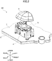
- FIG. 2 is a perspective view of an example of the internal configuration of the switch device 100.
- FIG. 2 corresponds to FIG. 1 in which a housing 1 is not depicted.
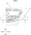
- FIG. 3 is a plan view of the switch device 100 of FIG. 1 .
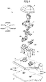
- FIG. 4 is an exploded perspective view of the switch device 100 of FIG. 2 .
- FIG. 5 is a cross-sectional view of the switch device 100 taken through A-A of FIG. 3 .
- FIG. 6 is a cross-sectional view of the switch device 100 taken through B-B of FIG. 3 .
- the directions (front, rear, left, right, upper, and lower directions) indicated in the figures will be described as the directions of the switch device 100; however, the directions of the switch device 100 are not limited thereto.
- the switch device 100 includes the housing 1, a substrate 2, an elastic resin layer 3, a support member 4, sliding members 5A and 5B, a driving member 6, a holding member 7, and an operation knob 8.
- the housing 1 houses the substrate 2, the elastic resin layer 3, the support member 4, the sliding members 5A and 5B, the driving member 6, and the holding member 7.
- the housing 1 may be formed integrally, or may be formed by a combination of a plurality of members as illustrated in the example of FIG. 1 .
- the housing 1 has an opening 11 through the upper surface, and the holding member 7 passes through the opening 11 to the outside of the housing 1.
- the opening 11 is formed such that the holding member 7 does not collide with the housing 1 when the operation knob 8 is moved in the front-rear direction.
- the substrate 2 is a printed circuit board, and is fixed to the housing 1.
- the substrate 2 may be a rigid substrate or a flexible substrate.
- a printed circuit is formed on the upper surface of the substrate 2.
- fixed contacts 21A and 21B are formed on the upper surface of the substrate 2.
- the fixed contact 21A is a contact constituting a switch 9A (first switch), and is located on the front side relative to the fixed contact 21B.
- the fixed contact 21A includes a plurality of contacts that are not electrically connected to each other.
- the fixed contact 21B is a contact constituting a switch 9B (second switch), and is located on the rear side relative to the fixed contact 21A.
- the fixed contact 21B includes a plurality of contacts that are not electrically connected to each other.
- the elastic resin layer 3 is an insulating layer formed on an elastic resin such as rubber, and is disposed on the substrate 2.
- the elastic resin layer 3 includes domes 31A and 31B and movable contacts 32A and 32B as illustrated in FIG. 5 .
- the dome 31A is a dome-shaped portion formed of an elastic resin, and is disposed above the fixed contact 21A to cover the fixed contact 21A.
- the movable contact 32A is a contact disposed on the lower surface of the top portion of the dome 31A, and contacts the fixed contact 21A when the dome 31A is pressed downward.
- the switch 9A is configured by the fixed contact 21A, the dome 31A, and the movable contact 32A.
- the switch 9A is turned on.
- the dome 31A Upon the completion of the pressing of the dome 31A, the dome 31A returns to the original shape (initial state) by the elastic force, and the movable contact 32A is separated from the fixed contact 21A. As a result, the switch 9A is turned off.
- the dome 31B is a dome-shaped portion formed of an elastic resin, and is disposed above the fixed contact 21B to cover the fixed contact 21B.
- the movable contact 32B is a contact disposed on the lower surface of the top portion of the dome 31B, and contacts the fixed contact 21B when the dome 31B is pressed downward.
- the switch 9B is configured by the fixed contact 21B, the dome 31B, and the movable contact 32B.
- the switch 9B is located on the rear side relative to the switch 9A.
- the switch 9B is turned on.
- the dome 31B Upon the completion of the pressing of the dome 31B, the dome 31B returns to the original shape (initial state) by the elastic force, and the movable contact 32B is separated from the fixed contact 21B. As a result, the switch 9B is turned off.
- the support member 4 has an approximately rectangular parallelepiped shape, and is disposed on the elastic resin layer 3.
- the support member 4 houses the sliding members 5A and 5B, the driving member 6, the switch 9A, and the switch 9B.
- the lower ends of the support member 4 are fixed to the elastic resin layer 3.
- the lower ends of the support member 4 may be fixed to the substrate 2 via through holes formed on the elastic resin layer 3.
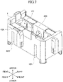
- FIG. 7 is a perspective view of the support member 4. As illustrated in FIG. 7 , the support member 4 includes a casing 41, a pair of slits 42A, a pair of slits 42B, and bearings 43A and 43B.
- the casing 41 is a through-hole in the upper-lower direction.
- the casing 41 is formed at the center of the support member 4, and extends in the front-rear direction.
- the sliding members 5A and 5B, the driving member 6, the switch 9A, and the switch 9B are disposed within the casing 41.
- the slits 42A guide the sliding member 5A such that the sliding member 5A slides in the upper-lower direction.
- the slits 42A extend upward from the bottom of the support member 4.
- the slits 42A are formed at positions opposite to each other on the left side surface and the right side surface of the support member 4.
- the slits 42B guide the sliding member 5B such that the sliding member 5B slides in the upper-lower direction.
- the slits 42B extend upward from the bottom of the support member 4.
- the slits 42B are formed at positions opposite to each other on the left side surface and the right side surface of the support member 4. As illustrated in FIG. 7 , the pair of slits 42B are located on the rear side relative to the pair of slits 42A.
- the bearing 43A is a recessed portion that rotatably supports a shaft 64A of the driving member 6, and is provided at the center of the left side surface of the support member 4.
- the bearing 43A supports the shaft 64A such that the shaft 64A can be moved downward from a reference position.
- the reference position is a position where the shaft 64A is located when the operation knob 8 is in the initial position, and corresponds to an upper end portion of the bearing 43A as illustrated in FIG. 6 .
- the bearing 43A becomes wider downward such that the shaft 64A can be moved downward from the reference position (the upper end portion of the bearing 43A).
- the bearing 43B is a recessed portion that rotatably supports a shaft 64B of the driving member 6, and is provided at the center of the right side surface of the support member 4.
- the bearing 43B is disposed opposite to the bearing 43A.
- the bearing 43B supports the shaft 64B such that the shaft 64B can be moved downward from a reference position.
- the reference position is a position where the shaft 64B is located when the operation knob 8 is in the initial position, and corresponds to an upper end portion of the bearing 43B.
- the bearing 43B becomes wider downward such that the shaft 64B can be moved downward from the reference position (the upper end portion of the bearing 43B).
- the sliding member 5A is a member that mediates the transmission of force between the driving member 6 and the switch 9A, and is disposed between the driving member 6 and the switch 9A as illustrated in FIG. 5 . More specifically, the sliding member 5A is disposed on the dome 31A, and a front portion 63A of a pressing portion 61 of the driving member 6 is disposed on the sliding member 5A.
- FIGS. 8 are perspective views of the sliding members 5A and 5B. As illustrated in FIG. 8 , the sliding member 5A includes a pair of guide portions 51A and a pressed portion 52A.
- the guide portions 51A are inserted into the slits 42A of the support member 4.
- the guide portions 51A are formed at positions opposite to each other on the left side surface and the right side surface of the support member 4, and project outward.
- the guide portions 51A By inserting the pair of guide portions 51A into the pair of slits 42A, the movement of the sliding member 5A in the front, rear, left, and right directions is restricted, and the sliding member 5A is slidably supported in the upper-lower direction.
- the guide portions 51A have plate shapes that are thinner than the slits 42A; however, the guide portions 51A may have any shape as long as the guide portions 51A can be inserted into the slits 42A.
- the pressed portion 52A is pressed by the pressing portion 61 of the driving member 6, and the center of the pressed portion 52A protrudes upward.
- the pressed portion 52A is preferably formed in a spherical or cylindrical shape, such that the driving member 6 can make uniform contact with the pressing portion 61 even when the driving member 6 is inclined.
- the sliding member 5B is a member that mediates the transmission of force between the driving member 6 and the switch 9B, and is disposed between the driving member 6 and the switch 9B as illustrated in FIG. 5 . More specifically, the sliding member 5B is disposed on the dome 31B, and a rear portion 63B of the pressing portion 61 of the driving member 6 is disposed on the sliding member 5B. As illustrated in FIG. 8 , the sliding member 5B includes a pair of guide portions 51B and a pressed portion 52B.
- the guide portions 51B are inserted into the slits 42B of the support member 4.
- the guide portions 51B are formed at positions opposite to each other on the left side surface and the right side surface of the support member 4, and project outward.
- the guide portions 51B By inserting the pair of guide portions 51B into the pair of slits 42B, the movement of the sliding member 5B in the front, rear, left, and right directions is restricted, and the sliding member 5B is slidably supported in the upper-lower direction.
- the guide portions 51B have plate shapes that are thinner than the slits 42B; however, the guide portions 51B may have any shape as long as the guide portions 51B can be inserted into the slits 42B.
- the pressed portion 52B is pressed by the pressing portion 61 of the driving member 6, and the center of the pressed portion 52B protrudes upward.
- the pressed portion 52B is preferably formed in a spherical or cylindrical shape, such that the driving member 6 can make uniform contact with the pressing portion 61 even when the driving member 6 is inclined.
- the driving member 6 is inclined in the front-rear direction (inclination direction) in accordance with the operation of the operation knob 8, and presses the switch 9A and switch 9B.
- the driving member 6 is disposed on the sliding members 5A and 5B, and is supported by the support member 4 such that the driving member 6 is inclined in the front-rear direction.
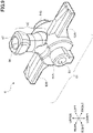
- FIG. 9 is a perspective view of the driving member 6. As illustrated in FIG. 9 , the driving member 6 includes the pressing portion 61 and a cam portion 62.
- the pressing portion 61 is a lower portion of the driving member 6, and extends over the switch 9A and the switch 9B in the front-rear direction. When the driving member 6 is inclined, the pressing portion 61 presses one of the switch 9A and the switch 9B.
- the pressing portion 61 includes the front portion 63A, the rear portion 63B, the shafts 64A and 64B, and a groove 65.
- the front portion 63A is a flat plateshaped portion located on the front side of the pressing portion 61.
- the front portion 63A is disposed on the pressed portion 52A of the sliding member 5A.
- the rear portion 63B is a flat plateshaped portion located on the rear side of the pressing portion 61.
- the rear portion 63B is disposed on the pressed portion 52B of the sliding member 5B.
- the shafts 64A and 64B are rotating shafts of the pressing portion 61.
- the shafts 64A and 64B are disposed opposite to each other on the right side surface and the left side surface at the center of the pressing portion 61.
- the groove 65 is a recess formed for minimizing sink marks. Grooves may be appropriately formed at the center of the side surface of each of the shafts 64A and 64B as illustrated in FIG. 9 , and at the center of the lower surface of the pressing portion 61 as illustrated in FIG. 5 .
- the reference positions of the shafts 64A and 64B correspond to the positions of the shafts 64A and 64B when the pressing portion 61 is disposed on the sliding members 5A and 5B.
- the bearings 43A and 43B are formed such that the upper end portions of the bearings 43A and 43B coincide with the reference positions of the shafts 64A and 64B.
- the cam portion 62 causes the driving member 6 to be inclined in the front-rear direction in accordance with the movement of the holding member 7 in the front-rear direction.
- the cam portion 62 extends upward from the center of the pressing portion 61.
- the cam portion 62 includes a first cam surface 66 and a second cam surface 67.
- the first cam surface 66 is a cam surface having a concave shape and formed at the upper end of the cam portion 62.
- the first cam surface 66 contacts a projecting portion 75 of the holding member 7.
- the second cam surface 67 is a cam surface having a convex shape and formed at the upper front and rear of the cam portion 62.
- the second cam surface 67 contacts a recessed portion 74 of the holding member 7.
- the holding member 7 is a member that holds the operation knob 8.
- the holding member 7 is disposed on the driving member 6 to project from the opening of the housing 1 upwardly relative to the upper surface of the housing 1.
- the holding member 7 holds the operation knob 8 at the upper end, and the holding member 7 moves in the front-rear direction together with the operation knob 8.
- the driving member 6 is inclined in the front-rear direction.
- FIG. 10 is a perspective view of the holding member 7. As illustrated in FIG. 10 , the holding member 7 includes a holding portion 71, a coupling portion 72, and a bottom portion 73.
- the holding portion 71 is a portion that holds the operation knob 8, and is provided at the upper end of the holding member 71.
- the holding portion 71 is located on the upper side relative to the housing 1.
- the holding portion 71 may hold the operation knob by engaging with the operation knob 8, or may be fixed to the operation knob 8 with an adhesive or a screw.
- the holding member 7 and the operation knob 8 may be integrally formed.
- the coupling portion 72 is a portion that connects the holding portion 71 to the bottom portion 73, and is inserted into the opening 11 of the housing 1 as illustrated in FIG. 5 .
- the coupling portion 72 becomes wider downward such that the recessed portion 74, which will be described
- the bottom portion 73 is a flat, plateshaped portion that restricts the movement of the holding member 71 in the upper-lower direction, and is provided at the lower end of the holding member 7.
- the bottom portion 73 is disposed between the support member 4 and the housing 1. More specifically, the bottom portion 73 is disposed such that the lower surface of the bottom portion 73 contacts the upper surface of the support member 4 and the upper surface of the bottom portion 73 contacts the lower surface of the housing 1.
- the movement of the holding member 71 in the upper-lower direction is restricted by the bottom portion 73 disposed between the support member 4 and the housing 1.
- the bottom portion 73 slides between the support member 4 and the housing 1 in the front-rear direction.
- the recessed portion 74 and the projecting portion 75 are formed at the center of the lower surface of the bottom portion 73.
- the recessed portion 74 is a portion into which the cam portion 62 of the driving member 6 is inserted, and extends from the lower surface of the bottom portion 73 to the lower portion of the coupling portion 72.
- the recessed portion 74 contacts the second cam surface 67.
- the recessed portion 74 becomes wider downward so as not to collide with the cam portion 62 when the driving member 6 is inclined.
- the projecting portion 75 is a portion that projects downward from the center of the recessed portion 74, and contacts the first cam surface 66.
- the holding member 7 is preferably disposed such that the projecting portion 75 is pressed upward by the first cam surface 66 due to the elastic force of the domes 31A and 31B when the operation knob 8 is in the initial position. Accordingly, it becomes possible to minimize backlash of the holding member 8 when the control knob 8 is in its initial position.
- the recessed portion 74 and the projecting portion 75 will be described later in detail.
- the operation knob is operated by the user in the front-rear direction.
- the operation knob 8 is held by the holding member 7 above the upper surface of the housing 1. When the operation knob 8 is not in operation, the operation knob 8 is in the initial position.
- FIG. 11 is a cross-sectional view of the switch device 100 taken through A-A of FIG. 3 when the operation knob 8 is moved forward.
- the holding member 7 moves forward together with the operation knob 8, thereby causing the recessed portion 74 to press the second cam surface 67 forward while causing the projecting portion 75 to press the first cam surface 66 downward.
- the driving member 6 moves downward while rotating forward about the shafts 64A and 64B. That is, the driving member 6 is inclined forward.
- the front portion 63A of the driving member 6 presses the sliding member 5A downward, the sliding member 5A moves downward, and the dome 31A is pressed downward.
- the shape of the dome 31A is elastically deformed and the top portion of the dome 31A moves downward.
- the dome 31A returns to the original shape by the elastic force, and the movable contact 32A is separated from the fixed contact 21A. As a result, the switch 9A is turned off. Further, the sliding member 5A is pressed upward by the dome 31A, moves upward, and presses the front portion 63A of the driving member 6 upward.
- the driving member 6 moves upward while rotating backward about the shafts 64A and 64B. That is, the driving member 6 is inclined backward.
- the second cam surface 67 presses the surface of the recessed portion 74 backward
- the first cam surface 66 presses the projecting portion 75 upward.
- the holding member 7 moves backward together with the operation knob 8.
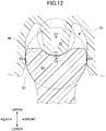
- FIG. 12 is an enlarged cross-sectional view of the vicinity of the cam portion 62 when the operation knob 8 is not operated.
- FIG. 13 is an enlarged cross-sectional view of the vicinity of the cam portion 62 when the operation knob 8 is operated.
- the first cam surface 66 and the projecting portion 75 it is preferable for the first cam surface 66 and the projecting portion 75 to contact each other both when the operation knob 8 is operated and when the operation knob 8 is not operated.
- the second cam surface 67 and the surface of the recessed portion 74 it is preferable for the cam portion 62 to contact the recessed portion 74 and the projecting portion 75 at the same time, both when the operation knob 8 is operated and when the operation knob 8 is not operated.
- first cam surface 66, the second cam surface 67, the recessed portion 74, and the projecting portion 75 are formed such that the distance from a contact point P1 between the first cam surface 66 and the projecting portion 75 to a contact point P2 between the second cam surface 67 and the recessed portion 74 decreases as the operation knob 8 moves away from the initial position (as the driving member 6 is inclined).
- each of the first cam surface 66 and the second cam surface 67 is preferably formed in a spherical shape in which the center of curvature C1 of the first cam surface 66 is located above the center of curvature C2 of the second cam surface 67, and portions of the recessed portion 74 that contact the second cam surface 67 are preferably formed in a cylindrical shape whose axis is parallel to the upper-lower direction.
- the operation knob 8 returns to the initial position by the elastic force of each of the dome 31A and the dome 31B having short operating strokes. Accordingly, in the switch device 100, the number of parts and the size of the switch device 100 can be reduced, as compared to the conventional switch device in which the operation knob is caused to return to the original position by the coil spring and the actuator having long operating strokes.
- the inclination direction of the driving member 6 is the front-rear direction; however, the inclination direction is not limited to the front-rear direction.
- the driving member 6 may be inclined in three or more directions.
- the switch 9A may be any switch that returns to the initial state by the elastic force.
- the switch 9A may be a switch including a metal dome (metal leaf spring) instead of the dome 31A and the movable contact 32B, or a tactile switch in which the movable contact 32A is disposed in a case. The same applies to the switch 9B.
Landscapes
- Switches With Compound Operations (AREA)
- Slide Switches (AREA)
Claims (8)
- Eine Schaltvorrichtung (100) aufweisend:einen ersten Schalter (9A) und einen zweiten Schalter (9B), jeweils konfiguriert, um in einen Ausgangszustand mittels einer elastischen Kraft zurückzukehren;ein Stützelement (4), welches den ersten Schalter und den zweiten Schalter aufnimmt;ein treibendes Element (6), welches mittels des Stützelements (4) gestützt ist, so dass das treibende Element (6) in einer vorbestimmten Neigungsrichtung geneigt ist es einen von dem ersten Schalter und dem zweiten Schalter drückt, wobei das treibende Element (6) fähig ist von der vorbestimmten Neigungsrichtung mittels der elastischen Kraft zurückzukehren;ein Haltelement (7), welches an dem treibenden Element (6) angeordnet ist, um das treibende Element (6) in der vorbestimmten Neigungsrichtung zu bewegen; undein Betätigungsknopf (8),welcher mittels des Halteelements (7) gehalten wird, wobei das treibende Element (6) aufweist einen pressenden Abschnitt (61), welcher angeordnet ist, um sich über den ersten Schalter (9A) und den zweiten Schalter (9B) zu erstrecken, und einen Nockenabschnitt (62), wobei der pressende Abschnitt (61) einen Schaft (64A) an einer Mitte davon aufweist, wobei der Nockenabschnitt (62) sich aufwärts von der Mitte des pressenden Abschnitts (61) erstreckt, und eine erste Nockenfläche (66), welche eine konkave Form aufweist, welche an einem oberen Ende von dem Nockenabschnitt (62) des treibenden Elements (6) gebildet ist, undwobei das Haltelement (7) einen ausgesparten Abschnitt (74) aufweist, in welchen der Nockenabschnitt (62) des treibenden Elements eingesetzt ist, und einen hervorstehenden Abschnitt (75), welcher nach unten von einer Mitte des ausgesparten Abschnitts (74) des Halteabschnitts (7) hervorsteht und die erste Nockenfläche (66) berührt.
- Die Schaltvorrichtung (100) gemäß Anspruch 1, wobei das Stützelement (4) ein Lager aufweist, welches den Schaft stützt, so dass der Schaft von einer Referenzposition nach unten bewegbar ist.
- Die Schaltvorrichtung (100) gemäß Anspruch 1 oder 2, wobei der Nockenabschnitt (62) den hervorstehenden Abschnitt (75) und den ausgesparten Abschnitt (74) zur selben Zeit berührt.
- Die Schaltvorrichtung (100) gemäß Anspruch 3, wobei ein Abstand von einem Kontaktpunkt zwischen dem Nockenabschnitt (62) und dem hervorstehenden Abschnitt (75) zu einem Kontaktpunkt zwischen dem Nockenabschnitt und dem ausgesparten Abschnitt (74) abnimmt, wenn das treibende Element (6) geneigt ist.
- Die Schaltvorrichtung (100) gemäß einem der Ansprüche 1 bis 4, wobei der Nockenabschnitt (62) eine zweite Nockenfläche (67) aufweist, welche eine konvexe Form aufweist und welche den ausgesparten Abschnitt berührt.
- Die Schaltvorrichtung (100) gemäß Anspruch 5, wobei die erste Nockenfläche (66) und die zweite Nockenfläche (67) jeweils in einer sphärischen Form ausgebildet sind.
- Die Schaltvorrichtung (100) gemäß Anspruch 5 oder 6, wobei eine Mitte einer Krümmung der ersten Nockenfläche (66) über einer Mitte einer Krümmung der zweiten Nockenfläche angeordnet ist.
- Die Schaltvorrichtung (100) gemäß einem der Ansprüche 1 bis 7, wobei der ausgesparte Abschnitt (74) nach unten weiter wird.
Applications Claiming Priority (2)
| Application Number | Priority Date | Filing Date | Title |
|---|---|---|---|
| JP2018058944 | 2018-03-26 | ||
| PCT/JP2018/043972 WO2019187343A1 (ja) | 2018-03-26 | 2018-11-29 | スイッチ装置 |
Publications (3)
| Publication Number | Publication Date |
|---|---|
| EP3780052A1 EP3780052A1 (de) | 2021-02-17 |
| EP3780052A4 EP3780052A4 (de) | 2021-12-08 |
| EP3780052B1 true EP3780052B1 (de) | 2023-01-04 |
Family
ID=68061218
Family Applications (1)
| Application Number | Title | Priority Date | Filing Date |
|---|---|---|---|
| EP18912325.0A Active EP3780052B1 (de) | 2018-03-26 | 2018-11-29 | Schaltvorrichtung |
Country Status (5)
| Country | Link |
|---|---|
| US (1) | US11037744B2 (de) |
| EP (1) | EP3780052B1 (de) |
| JP (1) | JP6857778B2 (de) |
| CN (1) | CN111712895B (de) |
| WO (1) | WO2019187343A1 (de) |
Families Citing this family (1)
| Publication number | Priority date | Publication date | Assignee | Title |
|---|---|---|---|---|
| WO2021261135A1 (ja) * | 2020-06-24 | 2021-12-30 | アルプスアルパイン株式会社 | スイッチ装置および組立方法 |
Family Cites Families (10)
| Publication number | Priority date | Publication date | Assignee | Title |
|---|---|---|---|---|
| JP2004288393A (ja) * | 2003-03-19 | 2004-10-14 | Alps Electric Co Ltd | 車両用パワーシートスイッチ装置 |
| JP4359478B2 (ja) * | 2003-10-14 | 2009-11-04 | アルプス電気株式会社 | ジョイスティック型スイッチ装置 |
| JP4720470B2 (ja) * | 2005-12-09 | 2011-07-13 | パナソニック株式会社 | 複合スイッチ |
| JP4985315B2 (ja) * | 2007-10-29 | 2012-07-25 | パナソニック株式会社 | プッシュスイッチ |
| JP4935875B2 (ja) * | 2009-09-04 | 2012-05-23 | 株式会社デンソー | 操作装置 |
| JP5626591B2 (ja) * | 2011-04-14 | 2014-11-19 | アルプス電気株式会社 | 入力装置 |
| CN105280423B (zh) * | 2014-07-17 | 2017-06-09 | 阿尔卑斯电气株式会社 | 转动式开关装置 |
| JP6414935B2 (ja) * | 2015-05-12 | 2018-10-31 | アルプス電気株式会社 | 回動式スイッチ装置 |
| WO2017038411A1 (ja) * | 2015-08-31 | 2017-03-09 | オムロン株式会社 | スイッチ |
| JP6893721B2 (ja) | 2016-10-03 | 2021-06-23 | モメンティブ・パフォーマンス・マテリアルズ・ジャパン合同会社 | 紫外線硬化型シリコーン樹脂組成物、及びそれを用いた物品 |
-
2018
- 2018-11-29 CN CN201880089552.0A patent/CN111712895B/zh active Active
- 2018-11-29 EP EP18912325.0A patent/EP3780052B1/de active Active
- 2018-11-29 WO PCT/JP2018/043972 patent/WO2019187343A1/ja unknown
- 2018-11-29 JP JP2020509618A patent/JP6857778B2/ja active Active
-
2020
- 2020-08-25 US US17/001,996 patent/US11037744B2/en active Active
Also Published As
| Publication number | Publication date |
|---|---|
| JP6857778B2 (ja) | 2021-04-14 |
| JPWO2019187343A1 (ja) | 2020-12-03 |
| CN111712895A (zh) | 2020-09-25 |
| CN111712895B (zh) | 2022-04-15 |
| WO2019187343A1 (ja) | 2019-10-03 |
| US11037744B2 (en) | 2021-06-15 |
| US20200388452A1 (en) | 2020-12-10 |
| EP3780052A4 (de) | 2021-12-08 |
| EP3780052A1 (de) | 2021-02-17 |
Similar Documents
| Publication | Publication Date | Title |
|---|---|---|
| US6914202B2 (en) | Two-step switch device | |
| US6784382B2 (en) | Push-on switch | |
| EP1760742B1 (de) | Schaltvorrichtung und Steuerungsschalter versehen mit dieser Schaltvorrichtung | |
| JP2020053123A (ja) | 多方向入力装置 | |
| US7462788B2 (en) | Switch device | |
| EP3780052B1 (de) | Schaltvorrichtung | |
| US11364435B2 (en) | Operation device | |
| US11211211B2 (en) | Control device for an electronic unit, methods for adjustment of the control device and motor vehicle rear view mirror with an integral device of that kind | |
| JP5698716B2 (ja) | スイッチ装置 | |
| KR100864388B1 (ko) | 복합 조작 입력 장치 | |
| EP3582243B1 (de) | Vierwegeschalter mit fehlfunktionverhinderungsstruktur | |
| JP7235630B2 (ja) | 多方向入力装置 | |
| CN107644751B (zh) | 操作单元的组装结构 | |
| JP5006293B2 (ja) | スライド操作機構およびこの機構を備えたスライド操作型スイッチ装置 | |
| JP3937670B2 (ja) | 多方向操作スイッチ | |
| JP2022043622A (ja) | プッシュスイッチ | |
| JP2002157943A (ja) | 揺動スイッチ | |
| JP7125557B2 (ja) | 操作装置 | |
| EP2571038B1 (de) | Schiebeschaltervorrichtung | |
| JP2003031076A (ja) | スライド操作式スイッチ | |
| US20230266787A1 (en) | Operation device | |
| JP5399295B2 (ja) | 多方向入力装置 | |
| JPH11162299A (ja) | 多機能型操作要素 | |
| JP2006294415A (ja) | 多方向入力スイッチ | |
| JP3352680B2 (ja) | キースイッチ装置 |
Legal Events
| Date | Code | Title | Description |
|---|---|---|---|
| STAA | Information on the status of an ep patent application or granted ep patent |
Free format text: STATUS: THE INTERNATIONAL PUBLICATION HAS BEEN MADE |
|
| PUAI | Public reference made under article 153(3) epc to a published international application that has entered the european phase |
Free format text: ORIGINAL CODE: 0009012 |
|
| STAA | Information on the status of an ep patent application or granted ep patent |
Free format text: STATUS: REQUEST FOR EXAMINATION WAS MADE |
|
| 17P | Request for examination filed |
Effective date: 20201007 |
|
| AK | Designated contracting states |
Kind code of ref document: A1 Designated state(s): AL AT BE BG CH CY CZ DE DK EE ES FI FR GB GR HR HU IE IS IT LI LT LU LV MC MK MT NL NO PL PT RO RS SE SI SK SM TR |
|
| AX | Request for extension of the european patent |
Extension state: BA ME |
|
| DAV | Request for validation of the european patent (deleted) | ||
| DAX | Request for extension of the european patent (deleted) | ||
| A4 | Supplementary search report drawn up and despatched |
Effective date: 20211105 |
|
| RIC1 | Information provided on ipc code assigned before grant |
Ipc: H01H 15/10 20060101ALN20211029BHEP Ipc: G05G 9/047 20060101ALN20211029BHEP Ipc: H01H 25/04 20060101AFI20211029BHEP |
|
| REG | Reference to a national code |
Ref country code: DE Ref legal event code: R079 Ref document number: 602018045194 Country of ref document: DE Free format text: PREVIOUS MAIN CLASS: H01H0021360000 Ipc: H01H0025040000 |
|
| RIC1 | Information provided on ipc code assigned before grant |
Ipc: H01H 15/10 20060101ALN20220622BHEP Ipc: G05G 9/047 20060101ALN20220622BHEP Ipc: H01H 25/04 20060101AFI20220622BHEP |
|
| GRAP | Despatch of communication of intention to grant a patent |
Free format text: ORIGINAL CODE: EPIDOSNIGR1 |
|
| STAA | Information on the status of an ep patent application or granted ep patent |
Free format text: STATUS: GRANT OF PATENT IS INTENDED |
|
| RIC1 | Information provided on ipc code assigned before grant |
Ipc: H01H 15/10 20060101ALN20220719BHEP Ipc: G05G 9/047 20060101ALN20220719BHEP Ipc: H01H 25/04 20060101AFI20220719BHEP |
|
| INTG | Intention to grant announced |
Effective date: 20220810 |
|
| GRAS | Grant fee paid |
Free format text: ORIGINAL CODE: EPIDOSNIGR3 |
|
| GRAA | (expected) grant |
Free format text: ORIGINAL CODE: 0009210 |
|
| STAA | Information on the status of an ep patent application or granted ep patent |
Free format text: STATUS: THE PATENT HAS BEEN GRANTED |
|
| AK | Designated contracting states |
Kind code of ref document: B1 Designated state(s): AL AT BE BG CH CY CZ DE DK EE ES FI FR GB GR HR HU IE IS IT LI LT LU LV MC MK MT NL NO PL PT RO RS SE SI SK SM TR |
|
| REG | Reference to a national code |
Ref country code: GB Ref legal event code: FG4D |
|
| REG | Reference to a national code |
Ref country code: CH Ref legal event code: EP |
|
| REG | Reference to a national code |
Ref country code: AT Ref legal event code: REF Ref document number: 1542539 Country of ref document: AT Kind code of ref document: T Effective date: 20230115 |
|
| REG | Reference to a national code |
Ref country code: DE Ref legal event code: R096 Ref document number: 602018045194 Country of ref document: DE |
|
| REG | Reference to a national code |
Ref country code: IE Ref legal event code: FG4D |
|
| REG | Reference to a national code |
Ref country code: LT Ref legal event code: MG9D |
|
| REG | Reference to a national code |
Ref country code: NL Ref legal event code: MP Effective date: 20230104 |
|
| REG | Reference to a national code |
Ref country code: AT Ref legal event code: MK05 Ref document number: 1542539 Country of ref document: AT Kind code of ref document: T Effective date: 20230104 |
|
| PG25 | Lapsed in a contracting state [announced via postgrant information from national office to epo] |
Ref country code: NL Free format text: LAPSE BECAUSE OF FAILURE TO SUBMIT A TRANSLATION OF THE DESCRIPTION OR TO PAY THE FEE WITHIN THE PRESCRIBED TIME-LIMIT Effective date: 20230104 |
|
| PG25 | Lapsed in a contracting state [announced via postgrant information from national office to epo] |
Ref country code: RS Free format text: LAPSE BECAUSE OF FAILURE TO SUBMIT A TRANSLATION OF THE DESCRIPTION OR TO PAY THE FEE WITHIN THE PRESCRIBED TIME-LIMIT Effective date: 20230104 Ref country code: PT Free format text: LAPSE BECAUSE OF FAILURE TO SUBMIT A TRANSLATION OF THE DESCRIPTION OR TO PAY THE FEE WITHIN THE PRESCRIBED TIME-LIMIT Effective date: 20230504 Ref country code: NO Free format text: LAPSE BECAUSE OF FAILURE TO SUBMIT A TRANSLATION OF THE DESCRIPTION OR TO PAY THE FEE WITHIN THE PRESCRIBED TIME-LIMIT Effective date: 20230404 Ref country code: LV Free format text: LAPSE BECAUSE OF FAILURE TO SUBMIT A TRANSLATION OF THE DESCRIPTION OR TO PAY THE FEE WITHIN THE PRESCRIBED TIME-LIMIT Effective date: 20230104 Ref country code: LT Free format text: LAPSE BECAUSE OF FAILURE TO SUBMIT A TRANSLATION OF THE DESCRIPTION OR TO PAY THE FEE WITHIN THE PRESCRIBED TIME-LIMIT Effective date: 20230104 Ref country code: HR Free format text: LAPSE BECAUSE OF FAILURE TO SUBMIT A TRANSLATION OF THE DESCRIPTION OR TO PAY THE FEE WITHIN THE PRESCRIBED TIME-LIMIT Effective date: 20230104 Ref country code: ES Free format text: LAPSE BECAUSE OF FAILURE TO SUBMIT A TRANSLATION OF THE DESCRIPTION OR TO PAY THE FEE WITHIN THE PRESCRIBED TIME-LIMIT Effective date: 20230104 Ref country code: AT Free format text: LAPSE BECAUSE OF FAILURE TO SUBMIT A TRANSLATION OF THE DESCRIPTION OR TO PAY THE FEE WITHIN THE PRESCRIBED TIME-LIMIT Effective date: 20230104 |
|
| PG25 | Lapsed in a contracting state [announced via postgrant information from national office to epo] |
Ref country code: SE Free format text: LAPSE BECAUSE OF FAILURE TO SUBMIT A TRANSLATION OF THE DESCRIPTION OR TO PAY THE FEE WITHIN THE PRESCRIBED TIME-LIMIT Effective date: 20230104 Ref country code: PL Free format text: LAPSE BECAUSE OF FAILURE TO SUBMIT A TRANSLATION OF THE DESCRIPTION OR TO PAY THE FEE WITHIN THE PRESCRIBED TIME-LIMIT Effective date: 20230104 Ref country code: IS Free format text: LAPSE BECAUSE OF FAILURE TO SUBMIT A TRANSLATION OF THE DESCRIPTION OR TO PAY THE FEE WITHIN THE PRESCRIBED TIME-LIMIT Effective date: 20230504 Ref country code: GR Free format text: LAPSE BECAUSE OF FAILURE TO SUBMIT A TRANSLATION OF THE DESCRIPTION OR TO PAY THE FEE WITHIN THE PRESCRIBED TIME-LIMIT Effective date: 20230405 Ref country code: FI Free format text: LAPSE BECAUSE OF FAILURE TO SUBMIT A TRANSLATION OF THE DESCRIPTION OR TO PAY THE FEE WITHIN THE PRESCRIBED TIME-LIMIT Effective date: 20230104 |
|
| REG | Reference to a national code |
Ref country code: DE Ref legal event code: R097 Ref document number: 602018045194 Country of ref document: DE |
|
| PG25 | Lapsed in a contracting state [announced via postgrant information from national office to epo] |
Ref country code: SM Free format text: LAPSE BECAUSE OF FAILURE TO SUBMIT A TRANSLATION OF THE DESCRIPTION OR TO PAY THE FEE WITHIN THE PRESCRIBED TIME-LIMIT Effective date: 20230104 Ref country code: RO Free format text: LAPSE BECAUSE OF FAILURE TO SUBMIT A TRANSLATION OF THE DESCRIPTION OR TO PAY THE FEE WITHIN THE PRESCRIBED TIME-LIMIT Effective date: 20230104 Ref country code: EE Free format text: LAPSE BECAUSE OF FAILURE TO SUBMIT A TRANSLATION OF THE DESCRIPTION OR TO PAY THE FEE WITHIN THE PRESCRIBED TIME-LIMIT Effective date: 20230104 Ref country code: DK Free format text: LAPSE BECAUSE OF FAILURE TO SUBMIT A TRANSLATION OF THE DESCRIPTION OR TO PAY THE FEE WITHIN THE PRESCRIBED TIME-LIMIT Effective date: 20230104 Ref country code: CZ Free format text: LAPSE BECAUSE OF FAILURE TO SUBMIT A TRANSLATION OF THE DESCRIPTION OR TO PAY THE FEE WITHIN THE PRESCRIBED TIME-LIMIT Effective date: 20230104 |
|
| PLBE | No opposition filed within time limit |
Free format text: ORIGINAL CODE: 0009261 |
|
| STAA | Information on the status of an ep patent application or granted ep patent |
Free format text: STATUS: NO OPPOSITION FILED WITHIN TIME LIMIT |
|
| PG25 | Lapsed in a contracting state [announced via postgrant information from national office to epo] |
Ref country code: SK Free format text: LAPSE BECAUSE OF FAILURE TO SUBMIT A TRANSLATION OF THE DESCRIPTION OR TO PAY THE FEE WITHIN THE PRESCRIBED TIME-LIMIT Effective date: 20230104 |
|
| 26N | No opposition filed |
Effective date: 20231005 |
|
| PG25 | Lapsed in a contracting state [announced via postgrant information from national office to epo] |
Ref country code: SI Free format text: LAPSE BECAUSE OF FAILURE TO SUBMIT A TRANSLATION OF THE DESCRIPTION OR TO PAY THE FEE WITHIN THE PRESCRIBED TIME-LIMIT Effective date: 20230104 |
|
| PGFP | Annual fee paid to national office [announced via postgrant information from national office to epo] |
Ref country code: DE Payment date: 20231121 Year of fee payment: 6 |