EP3779243B1 - Gangschaltvorrichtung - Google Patents
Gangschaltvorrichtung Download PDFInfo
- Publication number
- EP3779243B1 EP3779243B1 EP19777417.7A EP19777417A EP3779243B1 EP 3779243 B1 EP3779243 B1 EP 3779243B1 EP 19777417 A EP19777417 A EP 19777417A EP 3779243 B1 EP3779243 B1 EP 3779243B1
- Authority
- EP
- European Patent Office
- Prior art keywords
- rack
- take
- gear
- straight rail
- rail section
- Prior art date
- Legal status (The legal status is an assumption and is not a legal conclusion. Google has not performed a legal analysis and makes no representation as to the accuracy of the status listed.)
- Active
Links
Images



Classifications
-
- F—MECHANICAL ENGINEERING; LIGHTING; HEATING; WEAPONS; BLASTING
- F16—ENGINEERING ELEMENTS AND UNITS; GENERAL MEASURES FOR PRODUCING AND MAINTAINING EFFECTIVE FUNCTIONING OF MACHINES OR INSTALLATIONS; THERMAL INSULATION IN GENERAL
- F16H—GEARING
- F16H63/00—Control outputs from the control unit to change-speed- or reversing-gearings for conveying rotary motion or to other devices than the final output mechanism
- F16H63/02—Final output mechanisms therefor; Actuating means for the final output mechanisms
- F16H63/30—Constructional features of the final output mechanisms
- F16H63/304—Constructional features of the final output mechanisms the final output mechanisms comprising elements moved by electrical or magnetic force
-
- F—MECHANICAL ENGINEERING; LIGHTING; HEATING; WEAPONS; BLASTING
- F16—ENGINEERING ELEMENTS AND UNITS; GENERAL MEASURES FOR PRODUCING AND MAINTAINING EFFECTIVE FUNCTIONING OF MACHINES OR INSTALLATIONS; THERMAL INSULATION IN GENERAL
- F16H—GEARING
- F16H61/00—Control functions within control units of change-speed- or reversing-gearings for conveying rotary motion ; Control of exclusively fluid gearing, friction gearing, gearings with endless flexible members or other particular types of gearing
- F16H61/26—Generation or transmission of movements for final actuating mechanisms
- F16H61/28—Generation or transmission of movements for final actuating mechanisms with at least one movement of the final actuating mechanism being caused by a non-mechanical force, e.g. power-assisted
- F16H61/32—Electric motors , actuators or related electrical control means therefor
-
- F—MECHANICAL ENGINEERING; LIGHTING; HEATING; WEAPONS; BLASTING
- F16—ENGINEERING ELEMENTS AND UNITS; GENERAL MEASURES FOR PRODUCING AND MAINTAINING EFFECTIVE FUNCTIONING OF MACHINES OR INSTALLATIONS; THERMAL INSULATION IN GENERAL
- F16H—GEARING
- F16H19/00—Gearings comprising essentially only toothed gears or friction members and not capable of conveying indefinitely-continuing rotary motion
- F16H19/02—Gearings comprising essentially only toothed gears or friction members and not capable of conveying indefinitely-continuing rotary motion for interconverting rotary or oscillating motion and reciprocating motion
- F16H19/04—Gearings comprising essentially only toothed gears or friction members and not capable of conveying indefinitely-continuing rotary motion for interconverting rotary or oscillating motion and reciprocating motion comprising a rack
-
- F—MECHANICAL ENGINEERING; LIGHTING; HEATING; WEAPONS; BLASTING
- F16—ENGINEERING ELEMENTS AND UNITS; GENERAL MEASURES FOR PRODUCING AND MAINTAINING EFFECTIVE FUNCTIONING OF MACHINES OR INSTALLATIONS; THERMAL INSULATION IN GENERAL
- F16H—GEARING
- F16H19/00—Gearings comprising essentially only toothed gears or friction members and not capable of conveying indefinitely-continuing rotary motion
- F16H19/02—Gearings comprising essentially only toothed gears or friction members and not capable of conveying indefinitely-continuing rotary motion for interconverting rotary or oscillating motion and reciprocating motion
- F16H19/06—Gearings comprising essentially only toothed gears or friction members and not capable of conveying indefinitely-continuing rotary motion for interconverting rotary or oscillating motion and reciprocating motion comprising flexible members, e.g. an endless flexible member
-
- F—MECHANICAL ENGINEERING; LIGHTING; HEATING; WEAPONS; BLASTING
- F16—ENGINEERING ELEMENTS AND UNITS; GENERAL MEASURES FOR PRODUCING AND MAINTAINING EFFECTIVE FUNCTIONING OF MACHINES OR INSTALLATIONS; THERMAL INSULATION IN GENERAL
- F16H—GEARING
- F16H55/00—Elements with teeth or friction surfaces for conveying motion; Worms, pulleys or sheaves for gearing mechanisms
- F16H55/02—Toothed members; Worms
- F16H55/26—Racks
-
- F—MECHANICAL ENGINEERING; LIGHTING; HEATING; WEAPONS; BLASTING
- F16—ENGINEERING ELEMENTS AND UNITS; GENERAL MEASURES FOR PRODUCING AND MAINTAINING EFFECTIVE FUNCTIONING OF MACHINES OR INSTALLATIONS; THERMAL INSULATION IN GENERAL
- F16H—GEARING
- F16H57/00—General details of gearing
- F16H57/02—Gearboxes; Mounting gearing therein
-
- F—MECHANICAL ENGINEERING; LIGHTING; HEATING; WEAPONS; BLASTING
- F16—ENGINEERING ELEMENTS AND UNITS; GENERAL MEASURES FOR PRODUCING AND MAINTAINING EFFECTIVE FUNCTIONING OF MACHINES OR INSTALLATIONS; THERMAL INSULATION IN GENERAL
- F16H—GEARING
- F16H63/00—Control outputs from the control unit to change-speed- or reversing-gearings for conveying rotary motion or to other devices than the final output mechanism
- F16H63/02—Final output mechanisms therefor; Actuating means for the final output mechanisms
- F16H63/30—Constructional features of the final output mechanisms
-
- F—MECHANICAL ENGINEERING; LIGHTING; HEATING; WEAPONS; BLASTING
- F16—ENGINEERING ELEMENTS AND UNITS; GENERAL MEASURES FOR PRODUCING AND MAINTAINING EFFECTIVE FUNCTIONING OF MACHINES OR INSTALLATIONS; THERMAL INSULATION IN GENERAL
- F16H—GEARING
- F16H57/00—General details of gearing
- F16H57/02—Gearboxes; Mounting gearing therein
- F16H2057/02039—Gearboxes for particular applications
- F16H2057/02082—Gearboxes for particular applications for application in vehicles other than propelling, e.g. adjustment of parts
-
- F—MECHANICAL ENGINEERING; LIGHTING; HEATING; WEAPONS; BLASTING
- F16—ENGINEERING ELEMENTS AND UNITS; GENERAL MEASURES FOR PRODUCING AND MAINTAINING EFFECTIVE FUNCTIONING OF MACHINES OR INSTALLATIONS; THERMAL INSULATION IN GENERAL
- F16H—GEARING
- F16H61/00—Control functions within control units of change-speed- or reversing-gearings for conveying rotary motion ; Control of exclusively fluid gearing, friction gearing, gearings with endless flexible members or other particular types of gearing
- F16H61/26—Generation or transmission of movements for final actuating mechanisms
- F16H61/28—Generation or transmission of movements for final actuating mechanisms with at least one movement of the final actuating mechanism being caused by a non-mechanical force, e.g. power-assisted
- F16H2061/2876—Racks
-
- F—MECHANICAL ENGINEERING; LIGHTING; HEATING; WEAPONS; BLASTING
- F16—ENGINEERING ELEMENTS AND UNITS; GENERAL MEASURES FOR PRODUCING AND MAINTAINING EFFECTIVE FUNCTIONING OF MACHINES OR INSTALLATIONS; THERMAL INSULATION IN GENERAL
- F16H—GEARING
- F16H61/00—Control functions within control units of change-speed- or reversing-gearings for conveying rotary motion ; Control of exclusively fluid gearing, friction gearing, gearings with endless flexible members or other particular types of gearing
- F16H61/26—Generation or transmission of movements for final actuating mechanisms
- F16H61/28—Generation or transmission of movements for final actuating mechanisms with at least one movement of the final actuating mechanism being caused by a non-mechanical force, e.g. power-assisted
- F16H2061/2884—Screw-nut devices
-
- F—MECHANICAL ENGINEERING; LIGHTING; HEATING; WEAPONS; BLASTING
- F16—ENGINEERING ELEMENTS AND UNITS; GENERAL MEASURES FOR PRODUCING AND MAINTAINING EFFECTIVE FUNCTIONING OF MACHINES OR INSTALLATIONS; THERMAL INSULATION IN GENERAL
- F16H—GEARING
- F16H63/00—Control outputs from the control unit to change-speed- or reversing-gearings for conveying rotary motion or to other devices than the final output mechanism
- F16H63/02—Final output mechanisms therefor; Actuating means for the final output mechanisms
- F16H63/30—Constructional features of the final output mechanisms
- F16H63/304—Constructional features of the final output mechanisms the final output mechanisms comprising elements moved by electrical or magnetic force
- F16H2063/3059—Constructional features of the final output mechanisms the final output mechanisms comprising elements moved by electrical or magnetic force using racks
-
- F—MECHANICAL ENGINEERING; LIGHTING; HEATING; WEAPONS; BLASTING
- F16—ENGINEERING ELEMENTS AND UNITS; GENERAL MEASURES FOR PRODUCING AND MAINTAINING EFFECTIVE FUNCTIONING OF MACHINES OR INSTALLATIONS; THERMAL INSULATION IN GENERAL
- F16H—GEARING
- F16H63/00—Control outputs from the control unit to change-speed- or reversing-gearings for conveying rotary motion or to other devices than the final output mechanism
- F16H63/02—Final output mechanisms therefor; Actuating means for the final output mechanisms
- F16H63/30—Constructional features of the final output mechanisms
- F16H63/304—Constructional features of the final output mechanisms the final output mechanisms comprising elements moved by electrical or magnetic force
- F16H2063/3063—Constructional features of the final output mechanisms the final output mechanisms comprising elements moved by electrical or magnetic force using screw devices
Definitions
- the present invention relates to the technical field of gearbox shifting, and in particular to a shift drive.
- an electronic gearbox adapted to an electronic shift driver (SBW, Shift By Wire) is capable of receiving a shift signal transmitted from the SBW, thereby performing a shift operation.
- the publication No. CN205136570U Electronic Shift Driver for Automobiles
- a motor drives a driving wheel to rotate, and the driving wheel drives a screw to rotate via a belt and a driven wheel, so that a slider set on the screw moves axially.
- a bulge disposed on the slider can push against a rack to move it in a track, and then turn a magnetic gear to rotate. Rotation of the magnetic gear will produce a magnetic field change, so that a Hall sensor senses the magnetic field change to realize the gear identification information.
- the TCU adjusts the motor speed according to the gear identification information, and moves a push rod connected to the slider to a designated position, thereby completing the shift.
- the electronic shift driver including the above-described known embodiment provided by the present applicant can provide the electronic gearbox with the driving external force for performing the handover to the P gear, but cannot provide the external force for performing handover to R, N, and D gears.
- this type of electronic shift driver is applicable only to electronic gearboxes capable of receiving R-gear, N-gear, and D-gear signals, and cannot be expanded to automatic gearboxes of which other technologies are already mature. This limits the popularity of the electronic shift driver and makes it being not applicable to automatic gearboxes that are intended to maintain the existing configuration without technical reconstruction, but are intended to achieve the same shifting function as electronic shifters.
- WO2017170306 discloses a linear extension/retraction mechanism having a plurality of first and second pieces coupled together in a bendable manner, rollers joining join the first and second pieces together such that a pillar-like body is formed and supported such that it is movable forward and backward.
- a drive gear is provided for moving the first and second pieces forward and backward; and a motor unit for rotating the drive gear.
- Each of the first pieces includes, on a surface at a side to be joined to the corresponding second piece, a linear gear engaged with the drive gear, and includes a projection portion projected toward the second piece side.
- At least one third piece is connected to the rearmost first piece among the plurality of first pieces, in a bendable manner.
- a current collector system for a vehicle is vehicle that can be moved in a longitudinal direction along a power rail arrangement.
- the current collector system includes at least one current collector trolley, one or more current collector contacts arranged on the at least one current collector trolley and configured to be connected to power rails of the power rail arrangement, a telescopic arm configured to be fixed to the vehicle, and an adjustment drive comprising at least one rigid chain arrangement and at least a first rigid chain drive configured to extend and/or retract the telescopic arm.
- the telescopic arm comprises at least one telescopable telescopic stage, wherein an end of the rigid chain arrangement is connected to a most extendible telescopic stage of the at least one telescopable telescopic stage or to the current collector trolley in a fixed manner or is configured to be connected by means of a locking mechanism.
- An electronic shift driver as described in the above known embodiment which is only suitable for providing a gearbox with an external force for performing handover to the P gear, has a short stroke (generally about 17 mm) for its protrusion.
- the stroke of the protrusion will be greatly extended if it is intended to provide an automatic gearbox having existing known construction with an external force for performing handover to all gears including P, R, N and D gears.
- embodiments of the present invention provide a shift drive which can be applicable to an automatic gearbox of the existing known construction, such that the shift drive can achieve the same shifting function as an electronic shifter without technical retrofitting.
- the present invention provides the following technical solution.
- a shift drive comprising:
- the gear housing is provided thereon with a gear cover adapted thereto, and the gear cover is provided thereon with an elongated opening of which the connecting member extends out.
- the gear housing is provided with the take-up release section on at least one side of the straight rail section.
- the straight rail section may be located below the induction gear, and the take-up release section is disposed at at least one end of the straight rail section.
- both ends of the straight rail section are bent upward and downward, respectively, to form two take-up release sections which are located in the same plane as the straight rail section.
- connection portion is provided thereon with a rigid holding portion
- the connecting member is a protrusion extending from the rigid holding portion toward the actuating mechanism and inserted into a connecting hole provided in the actuating mechanism.
- the length of the straight rail section is set such that the connection portion can only slide freely therein along with the actuating mechanism.
- the rack is provided with a plurality of longitudinally spaced notches at least on a side wall near the end portion of the rack that is capable of a recoverable deformation, so that the end portion of the rack that is capable of a recoverable deformation is bent in a drag-reducing manner to enter the take-up release section.
- the driving mechanism comprises a motor
- the gear housing is provided with a magnetic field sensing element at a position corresponding to the induction gear
- the magnetic field sensing element and the motor are in signal connection to a central control unit of an automobile.
- the shift drive of the embodiment of the present invention by providing in the gear housing a take-up release section having a length projected on the extension line in the length direction of the straight rail section that is less than the length of the track thereof, the end portion of the rack being received in the track slot, that is capable of a recoverable deformation, can slide in or out of the take-up release section, so as to greatly extend the stroke of the rack under the premise of occupying the same space, so as to meet the requirement that the shift drive is applicable to the automatic gearbox which requires the rack has a long stroke.
- the shift drive according to the embodiment of the present invention can be applied to an automatic gearbox of an existing known construction without technical retrofitting, and can achieve the same shifting function as an electronic shifter.
- the shift drive according to the embodiment of the present invention has better versatility and it is easy to realize the modularization of the product.
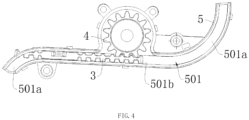
- the embodiment of the present invention provides a shift drive which may comprise: an actuating mechanism 6 capable of being driven by a driving mechanism 1, the actuating mechanism 6 being for connection to a gearbox (not shown); a rack 3 linked with the actuating mechanism 6, at least one end of the rack 3 being capable of a recoverable deformation, the rack 3 including a connection portion, the connection portion being connected to the actuating mechanism 6 through a connecting member 301; a gear housing 5() provided with an induction gear 4 that meshes with the rack 3, the gear housing 5 having a track slot 501 that receives the rack 3 therein, the track slot 501 having a take-up release section 501a and a straight rail section 501b, wherein an end portion of the rack 3 that is capable of a recoverable deformation can slide in or out of the take-up release section 501a, and the length of projection (the downward projection as shown in FIG. 3 ) of the take-up release section 501a on an extension line in the direction
- the shift drive of the embodiment of the present invention by providing in the gear housing 5 a take-up release section 501a having a length projected on the extension line in the length direction of the straight rail section 501b that is less than the length of the track thereof, the end portion of the rack 3 being received in the track slot 501, that is capable of a recoverable deformation, can slide in or out of the take-up release section 501a, so as to greatly extend the stroke of the rack 3 under the premise of occupying the same space, so as to meet the requirement that the shift drive is applicable to the automatic gearbox which requires the rack 3 has a long stroke.
- the shift drive according to the embodiment of the present invention can be applied to an automatic gearbox of an existing known construction without technical retrofitting, and can achieve the same shifting function as an electronic shifter.
- the shift drive according to the embodiment of the present invention has better versatility and it is easy to realize the modularization of the product.
- the actuating mechanism 6 may comprise a screw 601 which is externally sleeved with a slider 604 connected with a push rod 602 by a universal joint structure, the other end of the push rod 602 is connected to a socket shell 603 having a ball socket 603a, and the socket shell 603 is connected to a shift arm of the gearbox through the ball socket 603a.
- the driving mechanism 1 may comprise a motor 101, which may drive the screw 601 to rotate.
- the specific driving mode may be the belt drive provided by the above-mentioned known embodiment, and details thereof are disclosed in the present invention by way of reference, and are not repeated herein.
- a gear drive manner may be adopted.
- an output shaft of the motor 101 is provided with a driving gear 102
- the end of the screw 601 is provided with a driven gear 103
- the driving gear 102 may be directly meshed with the driven gear 103 to realize drive connection, or may be meshed with the driven gear 103 through an idle gear 104 to realize indirect drive.
- the connecting member 301 may be connected to the slider 604 or the push rod 602 so as to be connected to the actuating mechanism 6.
- the slider 604 or the push rod 602 is provided with a connecting hole adapted to the connecting member, and the connecting member 301 is inserted into the connecting hole.
- the rack 3 is substantially in the form of a flat strip having at least one end portion capable of a recoverable deformation (i.e., deformation not exceeding an elastic limit so that it can rebound to the original state), and the end portion is arranged corresponding to the take-up release section 501a such that at least the end portion of the rack 3 can adapt to the curvature change of the take-up release section 501a and thus enter the take-up release section 501a.
- a recoverable deformation i.e., deformation not exceeding an elastic limit so that it can rebound to the original state
- the rack 3 as a whole may have the performance of a recoverable deformation.
- the rack 3 is made of a flexible elastic material such as thermoplastic polyurethane elastomer rubber (TPU), so that the rack 3 can be deformed in any direction such that the rack 3 as a whole can be adaptively deformed in accordance with the shape of the track slot 501, so as to slide in or out of the take-up release section 501a, to meet the requirement that the shift drive is applicable to the automatic gearbox which requires the rack 3 has a long stroke.
- TPU thermoplastic polyurethane elastomer rubber
- the end portion of the rack 3 that is capable of a recoverable deformation When the end portion of the rack 3 that is capable of a recoverable deformation enters the take-up release section 501a, it may be radially bent such that the inner side of the rack 3 (the upper end as illustrated in FIG. 3 ) is compressed. This compression causes the rack 3 to have a tendency to rebound radially outward, thereby exerting a force on the inner wall of the take-up release section 501a, thus increasing the frictional force between the rack 3 and the inner wall of the take-up release section 501a, causing the rack 3 to be hindered from sliding.
- the rack 3 is provided with a plurality of longitudinally spaced notches 302 at least on a side wall near the end portion of the rack that is capable of a recoverable deformation
- the plurality of notches 302 may provide the rack 3 with a space for radial deformation upon entry into the take-up release section 501a, to reduce or even prevent the inner side of the rack 3 from being compressed, thereby reducing the frictional force between the rack 3 and the inner wall of the take-up release section 501a, ensuring that the end portion of the rack 3 that is capable of a recoverable deformation is bent in a drag-reducing manner to enter the take-up release section 501a, thereby ensuring that the rack 3 can slide smoothly.
- the gear housing 5 may be provided with a take-up release section 501a on at least one side of the straight rail section 501b, that is, there may be at least one take-up release section 501a.
- the straight rail section 501b is located below the induction gear 4, and the take-up release section 501a is disposed at at least one end of the straight rail section 501b.
- the take-up release section 501a is communicated with the straight rail section 501b in a smooth transition so as to reduce the occurrence of blocking and unsmooth sliding of the rack 3 at the connection between the two sections.
- take-up release sections 501a are preferably two, and specifically the two take-up release sections 501a may be formed by bending two ends of the straight rail section 501b upward and downward, respectively, so that the space size of the gear housing 5 can be fully utilized to increase the stroke of the rack 3 as much as possible.
- the two take-up release sections 501a and the straight rail section 501b are preferably located in the same plane so that the rack 3 can slide in or out of the take-up release sections 501a in a distortion-free manner, thereby maintaining the smoothness of sliding of the rack 3.
- the space in the vertical direction of the gear housing 5 can be fully utilized without increasing the space size in the direction perpendicular to the straight rail section 501b, so that the compact structure is ensured while the dimensional structure design is optimized, and thus the structure of the gear housing 5 tends to be miniaturized.
- the projection of the straight rail section 501b on a projection plane perpendicular to a horizontal plane is a straight line profile, which is in smooth transition to the take-up release sections 501a.
- the projection of the take-up release section 501a (since it lies in the same plane as the straight rail section 501b) on the projection plane described above is a circular arc profile, and the straight rail section 501b and the take-up release sections 501a are connected in a tangential manner at the junction.
- the projections of the take-up release sections 501a on the projection plane described above are a circular arc profile and a straight line profile, the circular arc profile being tangent to the straight rail section 501b and the straight line profile.
- the projections of the take-up release sections 501a on the projection plane described above are two circular arc profiles, the circular arc profile in the middle being tangent to the straight rail section 501b and the other circular arc profile.
- the take-up release sections 501a and the straight rail section 501b are located on the same plane, the take-up release sections 501a can be line projected on the extension line in the longitudinal direction of the straight rail section 501b. Then, the length of the take-up release sections 501a projected on the extension line in the length direction of the straight rail section 501b (the length of the dashed lines in FIGs. 5A to 5C ) is L', and the length of the its track (actually the circumference thereof) is L, wherein L' ⁇ L.
- the take-up release sections 501a may also be projected on the projection plane defined by the straight rail section 501b.
- upper and lower surfaces of the straight rail section 501b, or the horizontal surface when the shift drive according to the embodiment of the present invention is actually used, may be used as the projection surface.
- the projection length of the take-up release section 501a on such projection surface also satisfies the requirement of being less than its track length.
- connection portion is a part of the structure of the rack 3 itself, which may be a portion of the rack 3 that is close to the middle, or a portion where the rack 3 is connected to the connecting member 301 may be defined as the connection portion.
- the length of the straight rail section 501b is set such that the connection portion can slide freely only therein along with the actuating mechanism 6. Therefore, a portion of the rack 3 that moves only in the straight rail section 501b and does not enter the take-up release section 501a may also be defined as the connection portion.
- connection portion is connected to the driving mechanism 6 through the connecting member 301, the driving mechanism 6 drives the connection portion to move through the connecting member 301, thereby driving the rack 3 to move in the track slot 501.
- a shift signal triggers the motor 101 to rotate
- motor 101 is at a high speed and drives the actuating mechanism 6 from being stationary to move at a very high speed, resulting in a great acceleration.
- the driving mechanism 6 also converts this acceleration into an acting force applied to the connecting member 301, which further applies the acting force to the rack 3.
- the connecting member 301 and the rack 3 may be subjected to a great acting force, and the connecting member 301 may be deformed.
- the rack 3 is made of a flexible elastic material, it is also possible for the rack 3 to be bent and deformed radially or stacked at a portion corresponding to the connecting member 301.
- the connecting member 301 can be connected to the connection portion of the rack 3 through a rigid holding portion 7.
- the rigid holding portion 7 is preferably attached to the rack 3 in a covering manner (the covering portion is the connection portion) so as to increase the connection strength between the two, and has a thickness greater than that of the rack 3 so as to have a better rigidity.
- the connecting member 301 is preferably formed integrally with the rigid holding portion 7, and specifically may be formed as a protrusion extending from the rigid holding portion 7 toward the actuating mechanism 6 and inserted into a connecting hole provided in the actuating mechanism 6. In this way, the connecting member 301 and the rigid holding portion 7 have the same thickness that is larger than the thickness of the rack 3, thereby forming an increased thickness portion, and ensuring that the connecting member 301 has a rigidity that enables the rack 3 and the actuating mechanism 6 to be driven synchronously.
- connection portion covered by the rigid holding portion 7 and a rack section adjacent to the connection portion will not be bent and deformed or not be stacked, thereby ensuring better measurement accuracy.
- the rack 3 is required to slide in or out of the take-up release section 501a smoothly. From the above, it can be seen that in the present invention, the end portion of the rack 3 corresponding to the take-up release section 501a can smoothly enter the take-up release section 501a without stacking and blocking in such a manner that the rack 3 is made of a flexible elastic material so as to have better deformation performance.
- the rack 3 is required to have better deformation performance, and the part thereof corresponding to the connection portion has better rigidity, both of which are diametrically opposed or even contradictory.
- the rack 3 made of a flexible elastic material in combination with the notch 302 provided thereon may enable the rack 3 to have better deformation performance at least at the end thereof, so that the rack 3 can be bent in a drag-reducing manner and enter the take-up release section 501a smoothly.
- the connection portion of the rack 3 is connected to the connecting member 301 through the rigid holding portion 7, so that the rack 3 has better rigidity at a portion corresponding to the connection portion, to realize its synchronous transmission with the actuating mechanism 6.
- the length of the straight rail section 501 is set such that the rigid holding portion 7 is limited to slide only within the straight rail section 501b, that is, the rigid holding portion 7 moves linearly only within the straight rail section 501b of the track slot 501 and does not enter the take-up release section 501a of the track slot 501. In this way, it is ensured that the connecting member 301 and the rigid holding portion 7 will not be radially deformed and bent during sliding of the rack 3 within the straight rail section 501b.
- the gear housing 5 may be provided thereon with a gear cover 8 adapted thereto.
- the gear cover 8 is also provided with the same slot structure as the track slot 501, and the two slots form an inner space in which the rack 3 is accommodated after the gear housing 5 and the gear cover 8 are combined, so that the sliding of the rack 3 can be limited.
- the gear cover 8 is provided thereon with an elongated opening 801 of which the connecting member 301 extends out and which is corresponding to the straight rail section 501b of the track slot 501, the connecting member 301 passes through the elongated opening 801 to be connected to the actuating mechanism 6.
- the gear housing 5 is provided with a magnetic field sensing element (which may be for example, a Hall sensor) connected to the TCU by signal at a position thereof corresponding to the induction gear 4.
- a magnetic field sensing element which may be for example, a Hall sensor
- the motor 101 rotates after it receives the shift signal generated by the TCU in signal connection to the motor 101 based on the user's triggering operation, to drive the screw 601 to rotate, and the slider 604 sleeving outside the screw 601 and engaged with the screw 601 is axially moved, and the slider 604 pushes the push rod 602 to move, thereby driving the connecting member 301 inserted into the connecting hole of the slider 604 or the push rod 602 to move, then the connecting member 301 causes the rack 3 to slide in the track slot 501, so that the rack 3 turns the induction gear 4 to rotate by being engaged with the induction gear 4.
- Rotation of the induction gear 4 will produce a magnetic field change, so that the magnetic field sensing element senses the magnetic field change to realize the gear identification information.
- the TCU adjusts the rotational speed of the motor 101 or stops the motor 101 according to the gear identification information, moves the push rod 602 connected to the slider 604 to a designated position, and shifts the gear.
- the shift drive according to the embodiment of the present invention extends the stroke of the rack 3, it is possible not only to apply a shift driving force to the gearbox by the actuating mechanism 6 after a P gear signal is received, but also to apply the shift driving force to the gearbox after R, N, and D gear signals are received, such that it is possible to realize electronic shifting in a gearbox that doesn't have a capacity of receiving R, N, and D gear signals.
Landscapes
- Engineering & Computer Science (AREA)
- General Engineering & Computer Science (AREA)
- Mechanical Engineering (AREA)
- Gear-Shifting Mechanisms (AREA)
- Transmission Devices (AREA)
Claims (7)
- Ein Schaltantrieb, umfassend:einen Betätigungsmechanismus (6) zur Verbindung mit einem Getriebe;eine Zahnstange (3), die mit dem Betätigungsmechanismus (6) verbunden ist, wobei mindestens ein Ende der Zahnstange (3) rückstellbar verformt werden kann, wobei die Zahnstange (3) einen Verbindungsabschnitt beinhaltet, wobei der Verbindungsabschnitt über ein Verbindungselement (301) mit dem Betätigungsmechanismus (6) verbunden ist;ein Getriebegehäuse (5), das mit einem Induktionsgetriebe (4) versehen ist, das mit der Zahnstange (3) in Eingriff kommt, wobei das Getriebegehäuse (5) einen Spurschlitz (501) hat, der die Zahnstange (3) darin aufnimmt, wobei der Spurschlitz (501) einen geraden Schienenabschnitt (501b) und einen Aufnahmefreigabeabschnitt (501a) hat, wobei ein Endabschnitt der Zahnstange (3), der aus einer Verformung rückstellbar ist, in den Aufnahmefreigabeabschnitt (501a) hinein oder aus ihm heraus gleiten kann, wobei der Aufnahmefreigabeabschnitt (501a) eine Länge hat, die auf einer Verlängerungslinie in der Längsrichtung des geraden Schienenabschnitts (501b) projiziert ist, die kleiner ist als die Länge seiner Spurlänge,dadurch gekennzeichnet, dass das Getriebegehäuse (5) mit einem daran angepassten Getriebedeckel (8) versehen ist und der Getriebedeckel (8) mit einer länglichen Öffnung (801) darauf versehen ist, aus der sich das Verbindungselement (301) erstreckt.
- Der Schaltantrieb nach Anspruch 1, dadurch gekennzeichnet, dass das Getriebegehäuse (5) mit dem Aufnahmefreigabeabschnitt (501a) auf mindestens einer Seite des geraden Schienenabschnitts (501b) versehen ist.
- Der Schaltantrieb nach Anspruch 1, dadurch gekennzeichnet, dass beide Enden des geraden Schienenabschnitts (501b) jeweils in entgegengesetzte Richtungen gebogen sind, um zwei Aufnahmefreigabeabschnitte zu bilden, die in der gleichen Ebene wie der gerade Schienenabschnitt (501b) angeordnet sind.
- Der Schaltantrieb nach Anspruch 1, dadurch gekennzeichnet, dass der Verbindungsabschnitt mit einem starren Halteabschnitt (7) darauf versehen ist, und das Verbindungselement (310) ein Vorsprung ist, der sich von dem starren Halteabschnitt (7) in Richtung zum Betätigungsmechanismus (6) erstreckt und in ein Verbindungsloch eingesetzt ist, das in dem Betätigungsmechanismus (6) vorgesehen ist.
- Der Schaltantrieb nach Anspruch 1, dadurch gekennzeichnet, dass die Länge des geraden Schienenabschnitts (501b) so eingestellt ist, dass der Verbindungsabschnitt nur frei darin zusammen mit dem Betätigungsmechanismus (6) gleiten kann.
- Der Schaltantrieb nach Anspruch 1 oder 4, dadurch gekennzeichnet, dass die Zahnstange (3) mit einer Vielzahl von in Längsrichtung beabstandeten Kerben (302) zumindest an einer Seitenwand nahe dem Endabschnitt der Zahnstange (3) versehen ist, die rückstellbar verformt werden kann, so dass der Endabschnitt der Zahnstange (3), der rückstellbar verformt werden kann, in einer Widerstand reduzierenden Weise gebogen ist, um in den Aufnahmefreigabeabschnitt (501a) einzutreten.
- Der Schaltantrieb nach Anspruch 1, dadurch gekennzeichnet, dass der Antriebsmechanismus (6) einen Motor (101) umfasst, das Getriebegehäuse (5) mit einem Magnetfeldsensorelement an einer Position versehen ist, die dem Induktionsgetriebe (4) entspricht, und das Magnetfeldsensorelement und der Motor (101) in Signalverbindung mit einer zentralen Steuereinheit eines Kraftfahrzeugs stehen.
Applications Claiming Priority (2)
| Application Number | Priority Date | Filing Date | Title |
|---|---|---|---|
| CN201810295940.6A CN108302198B (zh) | 2018-03-30 | 2018-03-30 | 换挡驱动装置 |
| PCT/CN2019/079999 WO2019184964A1 (zh) | 2018-03-30 | 2019-03-28 | 换挡驱动装置 |
Publications (3)
| Publication Number | Publication Date |
|---|---|
| EP3779243A1 EP3779243A1 (de) | 2021-02-17 |
| EP3779243A4 EP3779243A4 (de) | 2021-12-01 |
| EP3779243B1 true EP3779243B1 (de) | 2023-08-23 |
Family
ID=62848275
Family Applications (1)
| Application Number | Title | Priority Date | Filing Date |
|---|---|---|---|
| EP19777417.7A Active EP3779243B1 (de) | 2018-03-30 | 2019-03-28 | Gangschaltvorrichtung |
Country Status (5)
| Country | Link |
|---|---|
| US (1) | US11566706B2 (de) |
| EP (1) | EP3779243B1 (de) |
| JP (1) | JP7256257B2 (de) |
| CN (1) | CN108302198B (de) |
| WO (1) | WO2019184964A1 (de) |
Families Citing this family (1)
| Publication number | Priority date | Publication date | Assignee | Title |
|---|---|---|---|---|
| CN108302198B (zh) * | 2018-03-30 | 2025-05-27 | 法可赛(太仓)汽车配件有限公司 | 换挡驱动装置 |
Family Cites Families (28)
| Publication number | Priority date | Publication date | Assignee | Title |
|---|---|---|---|---|
| GB190314089A (en) * | 1903-06-24 | 1904-04-21 | Joseph De Brouwer | Improvements in Apparatus for Discharging Coke from Through Gas Retorts. |
| US2755081A (en) * | 1951-10-08 | 1956-07-17 | Johnson Clarence | Garage door operators |
| JPS5854175A (ja) * | 1981-09-22 | 1983-03-31 | 日産自動車株式会社 | ウインドガラス昇降装置 |
| JPH0332107Y2 (de) * | 1985-10-31 | 1991-07-08 | ||
| DE3738416A1 (de) * | 1987-11-12 | 1989-05-24 | Bosch Gmbh Robert | Antrieb zum verstellen eines glieds, insbesondere eines riegelelements, das zum schliessmechanismus eines einer oeffnung in einer kraftfahrzeugkarosserie zugeordneten abdeckelements gehoert |
| DE4016708C2 (de) * | 1990-05-24 | 1994-07-21 | Baumeister & Ostler Gmbh Co | Abdeckung für den Laderaum eines PKW |
| AU5696494A (en) * | 1992-12-10 | 1994-07-04 | Girotto, Pietro | Electromagnetic actuator for door units and the like |
| NZ330098A (en) * | 1998-03-31 | 2000-09-29 | Howick Engineering Ltd | A rack and pinion door drive device for an automatic door with rack having bifurcate transverse section to locate onto rail of door track |
| DE19803541B4 (de) * | 1998-01-30 | 2005-08-11 | Zf Sachs Ag | Stelleinrichtung zur automatisierten Betätigung eines rotatorisch und translatorisch bewegbaren Schaltelements eines Schaltgetriebes |
| JP2001071810A (ja) * | 1999-09-07 | 2001-03-21 | Nissan Altia Co Ltd | 伸縮駆動装置及びドライブコードの製造方法 |
| US6694834B2 (en) | 2002-03-22 | 2004-02-24 | New Venture Gear, Inc. | Control system for transfer case range shift |
| DK1866556T3 (da) * | 2004-12-09 | 2010-10-04 | Kroeger Maskinfabrik As M | Leddelt drivmekanisme og dispenser omfattende en sådan drivmekanisme |
| JP5076840B2 (ja) * | 2007-11-28 | 2012-11-21 | アイシン精機株式会社 | 開閉体駆動用ラックベルト及び該開閉体駆動用ラックベルトを用いた開閉体駆動装置 |
| CN100594861C (zh) * | 2008-07-08 | 2010-03-24 | 北京航空航天大学 | 视觉融合功能训练器的标志物移动机构 |
| WO2010070915A1 (ja) * | 2008-12-19 | 2010-06-24 | 株式会社川渕機械技術研究所 | 直動伸縮機構及び当該直動伸縮機構を備えたロボットアーム |
| JP2011085238A (ja) * | 2009-10-19 | 2011-04-28 | Hi-Lex Corporation | パーキングロックアクチュエータ |
| JP2011144832A (ja) * | 2010-01-12 | 2011-07-28 | Tsubakimoto Chain Co | 噛合チェーン式進退作動装置 |
| CN201902543U (zh) | 2010-12-31 | 2011-07-20 | 三阳工业股份有限公司 | 模块化换档驱动装置 |
| CN202165585U (zh) | 2011-06-30 | 2012-03-14 | 长城汽车股份有限公司 | 内置式amt换挡驱动系 |
| JP5868296B2 (ja) * | 2012-09-06 | 2016-02-24 | 株式会社東海理化電機製作所 | 2軸ポジションセンサ及びそれを用いたシフトポジションセンサ |
| CN203047187U (zh) * | 2013-01-17 | 2013-07-10 | 昆明理工大学 | 一种雨刮器 |
| DE102014103741A1 (de) | 2014-03-19 | 2015-09-24 | Paul Vahle Gmbh & Co. Kg | Stromabnehmersystem mit Teleskoparm für Krane, Containerkrane, ERTGs und Fördereinrichtungen |
| CN205136570U (zh) * | 2015-11-04 | 2016-04-06 | 法可赛(太仓)汽车配件有限公司 | 用于汽车的电子换档驱动器 |
| CN205399614U (zh) * | 2016-03-12 | 2016-07-27 | 慈溪三和智能卫浴有限公司 | 温水便座弧形喷水管组件 |
| JP6734364B2 (ja) * | 2016-03-29 | 2020-08-05 | ライフロボティクス株式会社 | 直動伸縮機構及びロボットアーム機構 |
| CN106838303B (zh) | 2017-03-31 | 2019-02-22 | 法可赛(太仓)汽车配件有限公司 | 换挡驱动器及变速装置 |
| CN108302198B (zh) | 2018-03-30 | 2025-05-27 | 法可赛(太仓)汽车配件有限公司 | 换挡驱动装置 |
| CN208057921U (zh) * | 2018-03-30 | 2018-11-06 | 法可赛(太仓)汽车配件有限公司 | 换挡驱动装置 |
-
2018
- 2018-03-30 CN CN201810295940.6A patent/CN108302198B/zh active Active
-
2019
- 2019-03-28 JP JP2021501069A patent/JP7256257B2/ja active Active
- 2019-03-28 WO PCT/CN2019/079999 patent/WO2019184964A1/zh not_active Ceased
- 2019-03-28 EP EP19777417.7A patent/EP3779243B1/de active Active
- 2019-03-28 US US17/043,246 patent/US11566706B2/en active Active
Also Published As
| Publication number | Publication date |
|---|---|
| EP3779243A1 (de) | 2021-02-17 |
| EP3779243A4 (de) | 2021-12-01 |
| CN108302198A (zh) | 2018-07-20 |
| JP2021519406A (ja) | 2021-08-10 |
| WO2019184964A1 (zh) | 2019-10-03 |
| US20210025493A1 (en) | 2021-01-28 |
| CN108302198B (zh) | 2025-05-27 |
| JP7256257B2 (ja) | 2023-04-11 |
| US11566706B2 (en) | 2023-01-31 |
Similar Documents
| Publication | Publication Date | Title |
|---|---|---|
| US7146871B2 (en) | Vehicle running range switching device | |
| KR20080028795A (ko) | 언더컷이 없는 가이드 레일을 갖는 롤러 블라인드 | |
| US20180216390A1 (en) | Actuator and actuator for opening/closing vehicle door | |
| US9381900B2 (en) | Electric brake booster with transmission clearance compensation | |
| JPS612960A (ja) | 回転運動を直線運動に変換するギア装置 | |
| EP1156240B1 (de) | Elektrische betätigung zur getriebeschaltung | |
| US11566706B2 (en) | Shift drive | |
| JPWO2001031234A1 (ja) | 変速機用電動駆動装置 | |
| US11746899B2 (en) | Transmission with 1 axis shift mechanism | |
| JPH08228456A (ja) | 電子式センサを備える電動シリンダ | |
| EP0511351B1 (de) | Kabel zur genauen übertragung von längsbewegung | |
| CN208057921U (zh) | 换挡驱动装置 | |
| JP4244650B2 (ja) | 変速操作装置 | |
| EP3553346A1 (de) | Schaltungsaktuator | |
| US6880420B2 (en) | Automatic control device for a motorized vehicle gearbox | |
| CN114183505A (zh) | 变速箱及模型车 | |
| CN223868523U (zh) | 换挡机构、变速箱及车辆 | |
| CN115539630B (zh) | 换挡机构、动力总成及车辆 | |
| US11137055B2 (en) | Drive apparatus | |
| CN223318303U (zh) | 一种换挡机构及中置变速器 | |
| TWI294837B (en) | Shifting mechanism | |
| GB2384834A (en) | Gear shifting mechanism having a shift drum positioned by compression springs | |
| WO2014093860A1 (en) | Push down shifter with a cross joint | |
| US20080173117A1 (en) | Ball screw device | |
| US20250198507A1 (en) | Transmission control apparatus |
Legal Events
| Date | Code | Title | Description |
|---|---|---|---|
| STAA | Information on the status of an ep patent application or granted ep patent |
Free format text: STATUS: THE INTERNATIONAL PUBLICATION HAS BEEN MADE |
|
| PUAI | Public reference made under article 153(3) epc to a published international application that has entered the european phase |
Free format text: ORIGINAL CODE: 0009012 |
|
| STAA | Information on the status of an ep patent application or granted ep patent |
Free format text: STATUS: REQUEST FOR EXAMINATION WAS MADE |
|
| 17P | Request for examination filed |
Effective date: 20201030 |
|
| AK | Designated contracting states |
Kind code of ref document: A1 Designated state(s): AL AT BE BG CH CY CZ DE DK EE ES FI FR GB GR HR HU IE IS IT LI LT LU LV MC MK MT NL NO PL PT RO RS SE SI SK SM TR |
|
| AX | Request for extension of the european patent |
Extension state: BA ME |
|
| DAV | Request for validation of the european patent (deleted) | ||
| DAX | Request for extension of the european patent (deleted) | ||
| A4 | Supplementary search report drawn up and despatched |
Effective date: 20211103 |
|
| RIC1 | Information provided on ipc code assigned before grant |
Ipc: F16H 19/06 20060101ALI20211027BHEP Ipc: F16H 55/26 20060101ALI20211027BHEP Ipc: F16H 19/04 20060101ALI20211027BHEP Ipc: F16H 9/06 20060101ALI20211027BHEP Ipc: F16H 63/30 20060101ALI20211027BHEP Ipc: F16H 61/32 20060101AFI20211027BHEP |
|
| STAA | Information on the status of an ep patent application or granted ep patent |
Free format text: STATUS: EXAMINATION IS IN PROGRESS |
|
| 17Q | First examination report despatched |
Effective date: 20220920 |
|
| GRAP | Despatch of communication of intention to grant a patent |
Free format text: ORIGINAL CODE: EPIDOSNIGR1 |
|
| STAA | Information on the status of an ep patent application or granted ep patent |
Free format text: STATUS: GRANT OF PATENT IS INTENDED |
|
| INTG | Intention to grant announced |
Effective date: 20230314 |
|
| GRAS | Grant fee paid |
Free format text: ORIGINAL CODE: EPIDOSNIGR3 |
|
| GRAA | (expected) grant |
Free format text: ORIGINAL CODE: 0009210 |
|
| STAA | Information on the status of an ep patent application or granted ep patent |
Free format text: STATUS: THE PATENT HAS BEEN GRANTED |
|
| AK | Designated contracting states |
Kind code of ref document: B1 Designated state(s): AL AT BE BG CH CY CZ DE DK EE ES FI FR GB GR HR HU IE IS IT LI LT LU LV MC MK MT NL NO PL PT RO RS SE SI SK SM TR |
|
| REG | Reference to a national code |
Ref country code: GB Ref legal event code: FG4D |
|
| REG | Reference to a national code |
Ref country code: CH Ref legal event code: EP |
|
| REG | Reference to a national code |
Ref country code: IE Ref legal event code: FG4D |
|
| REG | Reference to a national code |
Ref country code: DE Ref legal event code: R096 Ref document number: 602019035680 Country of ref document: DE |
|
| REG | Reference to a national code |
Ref country code: LT Ref legal event code: MG9D |
|
| REG | Reference to a national code |
Ref country code: NL Ref legal event code: MP Effective date: 20230823 |
|
| REG | Reference to a national code |
Ref country code: AT Ref legal event code: MK05 Ref document number: 1602924 Country of ref document: AT Kind code of ref document: T Effective date: 20230823 |
|
| PG25 | Lapsed in a contracting state [announced via postgrant information from national office to epo] |
Ref country code: GR Free format text: LAPSE BECAUSE OF FAILURE TO SUBMIT A TRANSLATION OF THE DESCRIPTION OR TO PAY THE FEE WITHIN THE PRESCRIBED TIME-LIMIT Effective date: 20231124 |
|
| PG25 | Lapsed in a contracting state [announced via postgrant information from national office to epo] |
Ref country code: IS Free format text: LAPSE BECAUSE OF FAILURE TO SUBMIT A TRANSLATION OF THE DESCRIPTION OR TO PAY THE FEE WITHIN THE PRESCRIBED TIME-LIMIT Effective date: 20231223 |
|
| PG25 | Lapsed in a contracting state [announced via postgrant information from national office to epo] |
Ref country code: SE Free format text: LAPSE BECAUSE OF FAILURE TO SUBMIT A TRANSLATION OF THE DESCRIPTION OR TO PAY THE FEE WITHIN THE PRESCRIBED TIME-LIMIT Effective date: 20230823 Ref country code: RS Free format text: LAPSE BECAUSE OF FAILURE TO SUBMIT A TRANSLATION OF THE DESCRIPTION OR TO PAY THE FEE WITHIN THE PRESCRIBED TIME-LIMIT Effective date: 20230823 Ref country code: PT Free format text: LAPSE BECAUSE OF FAILURE TO SUBMIT A TRANSLATION OF THE DESCRIPTION OR TO PAY THE FEE WITHIN THE PRESCRIBED TIME-LIMIT Effective date: 20231226 Ref country code: NO Free format text: LAPSE BECAUSE OF FAILURE TO SUBMIT A TRANSLATION OF THE DESCRIPTION OR TO PAY THE FEE WITHIN THE PRESCRIBED TIME-LIMIT Effective date: 20231123 Ref country code: NL Free format text: LAPSE BECAUSE OF FAILURE TO SUBMIT A TRANSLATION OF THE DESCRIPTION OR TO PAY THE FEE WITHIN THE PRESCRIBED TIME-LIMIT Effective date: 20230823 Ref country code: LV Free format text: LAPSE BECAUSE OF FAILURE TO SUBMIT A TRANSLATION OF THE DESCRIPTION OR TO PAY THE FEE WITHIN THE PRESCRIBED TIME-LIMIT Effective date: 20230823 Ref country code: LT Free format text: LAPSE BECAUSE OF FAILURE TO SUBMIT A TRANSLATION OF THE DESCRIPTION OR TO PAY THE FEE WITHIN THE PRESCRIBED TIME-LIMIT Effective date: 20230823 Ref country code: IS Free format text: LAPSE BECAUSE OF FAILURE TO SUBMIT A TRANSLATION OF THE DESCRIPTION OR TO PAY THE FEE WITHIN THE PRESCRIBED TIME-LIMIT Effective date: 20231223 Ref country code: HR Free format text: LAPSE BECAUSE OF FAILURE TO SUBMIT A TRANSLATION OF THE DESCRIPTION OR TO PAY THE FEE WITHIN THE PRESCRIBED TIME-LIMIT Effective date: 20230823 Ref country code: GR Free format text: LAPSE BECAUSE OF FAILURE TO SUBMIT A TRANSLATION OF THE DESCRIPTION OR TO PAY THE FEE WITHIN THE PRESCRIBED TIME-LIMIT Effective date: 20231124 Ref country code: FI Free format text: LAPSE BECAUSE OF FAILURE TO SUBMIT A TRANSLATION OF THE DESCRIPTION OR TO PAY THE FEE WITHIN THE PRESCRIBED TIME-LIMIT Effective date: 20230823 Ref country code: AT Free format text: LAPSE BECAUSE OF FAILURE TO SUBMIT A TRANSLATION OF THE DESCRIPTION OR TO PAY THE FEE WITHIN THE PRESCRIBED TIME-LIMIT Effective date: 20230823 |
|
| PG25 | Lapsed in a contracting state [announced via postgrant information from national office to epo] |
Ref country code: PL Free format text: LAPSE BECAUSE OF FAILURE TO SUBMIT A TRANSLATION OF THE DESCRIPTION OR TO PAY THE FEE WITHIN THE PRESCRIBED TIME-LIMIT Effective date: 20230823 |
|
| PG25 | Lapsed in a contracting state [announced via postgrant information from national office to epo] |
Ref country code: ES Free format text: LAPSE BECAUSE OF FAILURE TO SUBMIT A TRANSLATION OF THE DESCRIPTION OR TO PAY THE FEE WITHIN THE PRESCRIBED TIME-LIMIT Effective date: 20230823 |
|
| PG25 | Lapsed in a contracting state [announced via postgrant information from national office to epo] |
Ref country code: SM Free format text: LAPSE BECAUSE OF FAILURE TO SUBMIT A TRANSLATION OF THE DESCRIPTION OR TO PAY THE FEE WITHIN THE PRESCRIBED TIME-LIMIT Effective date: 20230823 Ref country code: RO Free format text: LAPSE BECAUSE OF FAILURE TO SUBMIT A TRANSLATION OF THE DESCRIPTION OR TO PAY THE FEE WITHIN THE PRESCRIBED TIME-LIMIT Effective date: 20230823 Ref country code: ES Free format text: LAPSE BECAUSE OF FAILURE TO SUBMIT A TRANSLATION OF THE DESCRIPTION OR TO PAY THE FEE WITHIN THE PRESCRIBED TIME-LIMIT Effective date: 20230823 Ref country code: EE Free format text: LAPSE BECAUSE OF FAILURE TO SUBMIT A TRANSLATION OF THE DESCRIPTION OR TO PAY THE FEE WITHIN THE PRESCRIBED TIME-LIMIT Effective date: 20230823 Ref country code: DK Free format text: LAPSE BECAUSE OF FAILURE TO SUBMIT A TRANSLATION OF THE DESCRIPTION OR TO PAY THE FEE WITHIN THE PRESCRIBED TIME-LIMIT Effective date: 20230823 Ref country code: CZ Free format text: LAPSE BECAUSE OF FAILURE TO SUBMIT A TRANSLATION OF THE DESCRIPTION OR TO PAY THE FEE WITHIN THE PRESCRIBED TIME-LIMIT Effective date: 20230823 Ref country code: SK Free format text: LAPSE BECAUSE OF FAILURE TO SUBMIT A TRANSLATION OF THE DESCRIPTION OR TO PAY THE FEE WITHIN THE PRESCRIBED TIME-LIMIT Effective date: 20230823 |
|
| REG | Reference to a national code |
Ref country code: DE Ref legal event code: R097 Ref document number: 602019035680 Country of ref document: DE |
|
| PG25 | Lapsed in a contracting state [announced via postgrant information from national office to epo] |
Ref country code: IT Free format text: LAPSE BECAUSE OF FAILURE TO SUBMIT A TRANSLATION OF THE DESCRIPTION OR TO PAY THE FEE WITHIN THE PRESCRIBED TIME-LIMIT Effective date: 20230823 |
|
| PLBE | No opposition filed within time limit |
Free format text: ORIGINAL CODE: 0009261 |
|
| STAA | Information on the status of an ep patent application or granted ep patent |
Free format text: STATUS: NO OPPOSITION FILED WITHIN TIME LIMIT |
|
| 26N | No opposition filed |
Effective date: 20240524 |
|
| PG25 | Lapsed in a contracting state [announced via postgrant information from national office to epo] |
Ref country code: SI Free format text: LAPSE BECAUSE OF FAILURE TO SUBMIT A TRANSLATION OF THE DESCRIPTION OR TO PAY THE FEE WITHIN THE PRESCRIBED TIME-LIMIT Effective date: 20230823 |
|
| REG | Reference to a national code |
Ref country code: CH Ref legal event code: PL |
|
| PG25 | Lapsed in a contracting state [announced via postgrant information from national office to epo] |
Ref country code: BG Free format text: LAPSE BECAUSE OF FAILURE TO SUBMIT A TRANSLATION OF THE DESCRIPTION OR TO PAY THE FEE WITHIN THE PRESCRIBED TIME-LIMIT Effective date: 20230823 |
|
| PG25 | Lapsed in a contracting state [announced via postgrant information from national office to epo] |
Ref country code: LU Free format text: LAPSE BECAUSE OF NON-PAYMENT OF DUE FEES Effective date: 20240328 |
|
| PG25 | Lapsed in a contracting state [announced via postgrant information from national office to epo] |
Ref country code: MC Free format text: LAPSE BECAUSE OF FAILURE TO SUBMIT A TRANSLATION OF THE DESCRIPTION OR TO PAY THE FEE WITHIN THE PRESCRIBED TIME-LIMIT Effective date: 20230823 |
|
| GBPC | Gb: european patent ceased through non-payment of renewal fee |
Effective date: 20240328 |
|
| PG25 | Lapsed in a contracting state [announced via postgrant information from national office to epo] |
Ref country code: MC Free format text: LAPSE BECAUSE OF FAILURE TO SUBMIT A TRANSLATION OF THE DESCRIPTION OR TO PAY THE FEE WITHIN THE PRESCRIBED TIME-LIMIT Effective date: 20230823 Ref country code: LU Free format text: LAPSE BECAUSE OF NON-PAYMENT OF DUE FEES Effective date: 20240328 Ref country code: BG Free format text: LAPSE BECAUSE OF FAILURE TO SUBMIT A TRANSLATION OF THE DESCRIPTION OR TO PAY THE FEE WITHIN THE PRESCRIBED TIME-LIMIT Effective date: 20230823 |
|
| REG | Reference to a national code |
Ref country code: BE Ref legal event code: MM Effective date: 20240331 |
|
| PG25 | Lapsed in a contracting state [announced via postgrant information from national office to epo] |
Ref country code: BE Free format text: LAPSE BECAUSE OF NON-PAYMENT OF DUE FEES Effective date: 20240331 |
|
| PG25 | Lapsed in a contracting state [announced via postgrant information from national office to epo] |
Ref country code: GB Free format text: LAPSE BECAUSE OF NON-PAYMENT OF DUE FEES Effective date: 20240328 |
|
| PG25 | Lapsed in a contracting state [announced via postgrant information from national office to epo] |
Ref country code: FR Free format text: LAPSE BECAUSE OF NON-PAYMENT OF DUE FEES Effective date: 20240331 |
|
| PG25 | Lapsed in a contracting state [announced via postgrant information from national office to epo] |
Ref country code: IE Free format text: LAPSE BECAUSE OF NON-PAYMENT OF DUE FEES Effective date: 20240328 |
|
| PG25 | Lapsed in a contracting state [announced via postgrant information from national office to epo] |
Ref country code: IE Free format text: LAPSE BECAUSE OF NON-PAYMENT OF DUE FEES Effective date: 20240328 Ref country code: GB Free format text: LAPSE BECAUSE OF NON-PAYMENT OF DUE FEES Effective date: 20240328 Ref country code: FR Free format text: LAPSE BECAUSE OF NON-PAYMENT OF DUE FEES Effective date: 20240331 Ref country code: BE Free format text: LAPSE BECAUSE OF NON-PAYMENT OF DUE FEES Effective date: 20240331 Ref country code: CH Free format text: LAPSE BECAUSE OF NON-PAYMENT OF DUE FEES Effective date: 20240331 |
|
| PG25 | Lapsed in a contracting state [announced via postgrant information from national office to epo] |
Ref country code: CY Free format text: LAPSE BECAUSE OF FAILURE TO SUBMIT A TRANSLATION OF THE DESCRIPTION OR TO PAY THE FEE WITHIN THE PRESCRIBED TIME-LIMIT; INVALID AB INITIO Effective date: 20190328 |
|
| PG25 | Lapsed in a contracting state [announced via postgrant information from national office to epo] |
Ref country code: HU Free format text: LAPSE BECAUSE OF FAILURE TO SUBMIT A TRANSLATION OF THE DESCRIPTION OR TO PAY THE FEE WITHIN THE PRESCRIBED TIME-LIMIT; INVALID AB INITIO Effective date: 20190328 |
|
| PG25 | Lapsed in a contracting state [announced via postgrant information from national office to epo] |
Ref country code: TR Free format text: LAPSE BECAUSE OF FAILURE TO SUBMIT A TRANSLATION OF THE DESCRIPTION OR TO PAY THE FEE WITHIN THE PRESCRIBED TIME-LIMIT Effective date: 20230823 |
|
| PGFP | Annual fee paid to national office [announced via postgrant information from national office to epo] |
Ref country code: DE Payment date: 20260327 Year of fee payment: 8 |