EP3776824B1 - Moteur pour dispositif de soins personnels - Google Patents
Moteur pour dispositif de soins personnels Download PDFInfo
- Publication number
- EP3776824B1 EP3776824B1 EP19718315.5A EP19718315A EP3776824B1 EP 3776824 B1 EP3776824 B1 EP 3776824B1 EP 19718315 A EP19718315 A EP 19718315A EP 3776824 B1 EP3776824 B1 EP 3776824B1
- Authority
- EP
- European Patent Office
- Prior art keywords
- stator
- rotor
- spacer
- motor
- airgap
- Prior art date
- Legal status (The legal status is an assumption and is not a legal conclusion. Google has not performed a legal analysis and makes no representation as to the accuracy of the status listed.)
- Active
Links
- 125000006850 spacer group Chemical group 0.000 claims description 192
- 238000003475 lamination Methods 0.000 claims description 68
- 239000000463 material Substances 0.000 claims description 25
- 238000000034 method Methods 0.000 claims description 15
- 238000004519 manufacturing process Methods 0.000 claims description 14
- 239000011248 coating agent Substances 0.000 claims description 4
- 238000000576 coating method Methods 0.000 claims description 4
- 230000003993 interaction Effects 0.000 claims description 4
- CWYNVVGOOAEACU-UHFFFAOYSA-N Fe2+ Chemical compound [Fe+2] CWYNVVGOOAEACU-UHFFFAOYSA-N 0.000 description 10
- XEEYBQQBJWHFJM-UHFFFAOYSA-N Iron Chemical compound [Fe] XEEYBQQBJWHFJM-UHFFFAOYSA-N 0.000 description 9
- 238000010586 diagram Methods 0.000 description 9
- 230000000717 retained effect Effects 0.000 description 9
- 229910001369 Brass Inorganic materials 0.000 description 6
- 239000010951 brass Substances 0.000 description 6
- 230000000295 complement effect Effects 0.000 description 4
- 230000008569 process Effects 0.000 description 3
- 229910052742 iron Inorganic materials 0.000 description 2
- 238000000926 separation method Methods 0.000 description 2
- 238000012360 testing method Methods 0.000 description 2
- 208000019300 CLIPPERS Diseases 0.000 description 1
- 229930040373 Paraformaldehyde Natural products 0.000 description 1
- 239000000853 adhesive Substances 0.000 description 1
- 230000001070 adhesive effect Effects 0.000 description 1
- 230000004075 alteration Effects 0.000 description 1
- 230000015572 biosynthetic process Effects 0.000 description 1
- 208000021930 chronic lymphocytic inflammation with pontine perivascular enhancement responsive to steroids Diseases 0.000 description 1
- 238000013461 design Methods 0.000 description 1
- 238000012986 modification Methods 0.000 description 1
- 230000004048 modification Effects 0.000 description 1
- 230000003534 oscillatory effect Effects 0.000 description 1
- -1 polyoxymethylene Polymers 0.000 description 1
- 229920006324 polyoxymethylene Polymers 0.000 description 1
- 238000012545 processing Methods 0.000 description 1
- 230000003068 static effect Effects 0.000 description 1
- 238000004804 winding Methods 0.000 description 1
Images


Classifications
-
- H—ELECTRICITY
- H02—GENERATION; CONVERSION OR DISTRIBUTION OF ELECTRIC POWER
- H02K—DYNAMO-ELECTRIC MACHINES
- H02K33/00—Motors with reciprocating, oscillating or vibrating magnet, armature or coil system
- H02K33/16—Motors with reciprocating, oscillating or vibrating magnet, armature or coil system with polarised armatures moving in alternate directions by reversal or energisation of a single coil system
-
- H—ELECTRICITY
- H02—GENERATION; CONVERSION OR DISTRIBUTION OF ELECTRIC POWER
- H02K—DYNAMO-ELECTRIC MACHINES
- H02K21/00—Synchronous motors having permanent magnets; Synchronous generators having permanent magnets
- H02K21/02—Details
- H02K21/021—Means for mechanical adjustment of the excitation flux
- H02K21/022—Means for mechanical adjustment of the excitation flux by modifying the relative position between field and armature, e.g. between rotor and stator
- H02K21/025—Means for mechanical adjustment of the excitation flux by modifying the relative position between field and armature, e.g. between rotor and stator by varying the thickness of the air gap between field and armature
- H02K21/026—Axial air gap machines
-
- A—HUMAN NECESSITIES
- A46—BRUSHWARE
- A46B—BRUSHES
- A46B13/00—Brushes with driven brush bodies or carriers
- A46B13/02—Brushes with driven brush bodies or carriers power-driven carriers
-
- A—HUMAN NECESSITIES
- A46—BRUSHWARE
- A46B—BRUSHES
- A46B9/00—Arrangements of the bristles in the brush body
- A46B9/02—Position or arrangement of bristles in relation to surface of the brush body, e.g. inclined, in rows, in groups
- A46B9/04—Arranged like in or for toothbrushes
-
- A—HUMAN NECESSITIES
- A61—MEDICAL OR VETERINARY SCIENCE; HYGIENE
- A61C—DENTISTRY; APPARATUS OR METHODS FOR ORAL OR DENTAL HYGIENE
- A61C17/00—Devices for cleaning, polishing, rinsing or drying teeth, teeth cavities or prostheses; Saliva removers; Dental appliances for receiving spittle
- A61C17/16—Power-driven cleaning or polishing devices
- A61C17/22—Power-driven cleaning or polishing devices with brushes, cushions, cups, or the like
-
- H—ELECTRICITY
- H02—GENERATION; CONVERSION OR DISTRIBUTION OF ELECTRIC POWER
- H02K—DYNAMO-ELECTRIC MACHINES
- H02K7/00—Arrangements for handling mechanical energy structurally associated with dynamo-electric machines, e.g. structural association with mechanical driving motors or auxiliary dynamo-electric machines
- H02K7/14—Structural association with mechanical loads, e.g. with hand-held machine tools or fans
- H02K7/145—Hand-held machine tool
-
- H—ELECTRICITY
- H02—GENERATION; CONVERSION OR DISTRIBUTION OF ELECTRIC POWER
- H02K—DYNAMO-ELECTRIC MACHINES
- H02K2201/00—Specific aspects not provided for in the other groups of this subclass relating to the magnetic circuits
- H02K2201/03—Machines characterised by aspects of the air-gap between rotor and stator
-
- H—ELECTRICITY
- H02—GENERATION; CONVERSION OR DISTRIBUTION OF ELECTRIC POWER
- H02K—DYNAMO-ELECTRIC MACHINES
- H02K2205/00—Specific aspects not provided for in the other groups of this subclass relating to casings, enclosures, supports
- H02K2205/03—Machines characterised by thrust bearings
-
- H—ELECTRICITY
- H02—GENERATION; CONVERSION OR DISTRIBUTION OF ELECTRIC POWER
- H02K—DYNAMO-ELECTRIC MACHINES
- H02K7/00—Arrangements for handling mechanical energy structurally associated with dynamo-electric machines, e.g. structural association with mechanical driving motors or auxiliary dynamo-electric machines
- H02K7/08—Structural association with bearings
Definitions
- Embodiments of the present invention relate generally to motors for personal care devices, such as, for example, power toothbrushes, power shavers and skin care devices.
- a drivetrain in a personal care device is an electromagnetic module which creates the necessary movements of the device.
- the drivetrain creates the oscillatory movements of the brush head.
- the drivetrain comprises a motor, which includes a rotor and a stator.
- the rotor and stator are separated by an airgap, which is important for correct operation of the motor. If the airgap is closed, the friction force between the rotor and the stator may prevent relative motion.
- US 2017/040867 discloses a motor which includes a spacer between the rotating portion of the motor and the static portion of the motor.
- the spacer is a substantially annular plate-shaped member.
- a spacer is permanently provided between the rotor and the stator to define the minimum airgap.
- the presence of the spacer between the rotor and the stator prevents airgap closure since the rotor and stator are not able to completely come together.
- the spacer prevents the rotor surface and the stator surface from coming into direct contact with each other (at any point other than at the spacer contact surface), and maintains a distance between the stator and the rotor.
- the size of the spacer determines the (minimum) size of the airgap and so the length of the projection may correspond to the desired airgap size. Accordingly, a longer spacer (i.e. one that projects further from the rotor surface or the stator surface) will result in a larger distance between the stator and the rotor, and therefore a larger airgap, while a spacer with a shorter projection will define a smaller airgap.
- the rotor and the stator are arranged adjacent to each other, with each having a surface at the interface which opposes the other surface, i.e. they are arranged such that the stator surface faces the rotor surface.
- the spacer is disposed on or at either the stator surface or the rotor surface and so the minimum airgap is defined between these surfaces. If the spacer is disposed on or at the stator surface, then a contact surface of the spacer is configured to contact the rotor surface such that the rotor may be abutted against the spacer, with contact occurring between the rotor surface and the contact surface. Conversely, if the spacer is provided on the rotor surface, then the contact surface of the spacer is configured to contact the stator surface of the stator, and the stator may abut against the contact surface of the spacer.
- the spacer is disposed on or at one of the rotor surface and the stator surface, and is separated from the other one of the rotor surface and the stator surface.
- the separation may be in the range of, for example, 0.1 mm to 5mm.
- the contact surface may therefore be configured to, adapted to or capable of engaging with (i.e. contacting) the rotor surface or the stator surface, yet may not actually engage with or contact the rotor surface or the stator surface.
- the minimum airgap is therefore explicitly set by the components of the motor (i.e. the spacer), such that calibration/setting of the airgap is integrated in the device.
- the airgap may automatically be set to a correct minimum size and maintained during the lifetime of the drivetrain by the spacer.
- the spacer corresponds to a minimum airgap between the rotor and the stator, yet the spacer does not determine the maximum airgap. That is, the airgap may be larger than the length of the projection of the spacer since a separation or gap may be provided between the distal end of the spacer and the surface of the rotor or the stator which the spacer is configured to engage with or contact.
- the airgap may be set to a desired distance but that the spacer is provided as a 'back-up' to ensure that a minimum distance is always provided between the rotor and the stator.
- the motor may be provided as part of a drivetrain.
- the presence of the spacer, and its arrangement between the stator and the rotor, defines and maintains the minimum airgap. It may be considered that the spacer is disposed on or at the stator surface or the rotor surface at its proximal end, and that the contact surface of the spacer is at its distal end, which contacts the other one of the stator surface or the rotor surface.
- the spacer may also be referred to as a spacer element, projection, protrusion, jut, bearing or bearing point. Since the spacer projects from the stator surface or the rotor surface, it is evident that the surface area of the contact surface of the spacer is smaller than each of the surface area of the stator surface and surface area of the rotor surface.
- More than one spacer may be provided, each of the one or more spacers being disposed on or at one of the rotor surface and the stator surface, and each comprising a contact surface configured to engage with (i.e. contact) the other one of the rotor surface and the stator surface.
- the rotor and stator are arranged in the motor such that the rotor is configured to at least partially rotate with respect to the stator, the rotor rotating about a rotation axis.
- the spacer is aligned with the rotation axis of the rotor. That is, the spacer may preferably be disposed at the rotation center of the rotor. Mutual friction between the spacer and the rotor surface or stator surface may therefore be reduced since the spacer contacts the center point of the rotor surface or stator surface.
- the spacer is at least partially formed from one or more of: a wear resistant material; a material with a low coefficient of friction; and an impact resistant material.
- a wear resistant material is polyoxymethylene.
- At least the contact surface of the spacer is preferably formed from such a material. The material may improve the durability and lifespan of the spacer, as well as reducing the friction between the spacer, specifically the contact surface of the spacer, and the rotor surface or the stator surface.
- a portion of the stator surface or rotor surface configured to engage with the spacer may be provided by or formed from a material which is wear resistant, has a low coefficient of friction, and/or is impact resistant.
- the form of the spacer may vary.
- the spacer may be a ball bearing which may at least partially rotate with respect to the rotor and the stator.
- the ball bearing may be retained in a socket on the rotor surface or the stator surface such that it may rotate freely within the socket.
- the surface of the ball bearing protruding from the socket then forms the contact surface. Since the ball bearing freely moves with respect to both the stator and the rotor, friction may be reduced between the ball bearing and the surfaces of the rotor and stator.
- the spacer is formed on or connected to the stator such that the spacer projects from at least part of the stator surface. That is, it is preferable that the spacer is disposed on or at the stator surface, such that it extends from the stator surface and is configured to engage with (i.e. contact) the rotor surface at the contact surface.
- the spacer may be attached to or incorporated into the stator in any suitable way, examples of which are provided in the detailed description.
- the stator surface may be configured to receive a plate comprising the spacer. That is, a plate in which the spacer is incorporated may be attached to the stator surface by means of interconnection or fixation between the plate and the stator surface.
- the stator surface may comprise a recess configured to receive a spacer plate, and the recess may be provided with crush ribs or snaps at its periphery to retain the spacer plate in the recess.
- the rotor surface may be similarly configured to receive a plate comprising the spacer.
- the stator may preferably comprise a core formed of a plurality of laminations, and the spacer may be a projection extending from at least one of the ends of the laminations of the core. That is, the laminations, such as iron laminations, may be arranged in the stator such that the ends of the laminations provide at least part of the stator surface, from which a projection of one or more ends of the laminations may extend to provide the spacer.
- the laminations such as iron laminations
- the stator may comprise more than one core formed of a plurality of laminations and each core may comprise a projection to provide more than one spacer. That is, a projection may extend from one or more ends of the laminations in each core (i.e. a projection may extend from each of the core ends) thereby providing multiple spacer elements, with the distal end of each projection configured to engage with the rotor surface. According to this embodiment, it may be seen that the ends of each of the cores each form at least part of the stator surface. In a preferred embodiment, the stator comprises two cores.
- the one or more of the ends of the one or more cores may be configured to receive a plate comprising the spacer. That is, the end(s) of the core(s) may be shaped to receive a spacer plate. For example, the end(s) of the core(s) may be provided with a step for receiving a spacer plate.
- the stator may also comprise a bobbin, in which the one or more cores are arranged and held.
- the end of the bobbin may provide at least part of the stator surface, such that the spacer may be disposed or formed on the end of the bobbin.
- the bobbin may comprise multiple parts, such as two complementary bobbin halves.
- At least part of the rotor surface may have a low friction coating. Additionally or alternatively, at least part of the stator surface may have a low friction coating. Thus the mutual friction between the spacer and the stator surface or rotor surface may be reduced. Similarly, a plate made of a low friction and/or wear resistant material may be provided on at least part of the rotor surface. A plate made of a low friction and/or wear resistant material may be provided on at least part of the stator surface.
- the contact surface of the spacer is curved. That is, the distal end of the spacer is rounded, curved, or has a hemispherical type shape to provide a curved contact surface.
- the contact area between the spacer and the stator surface or the rotor surface at the contact surface of the spacer may thereby be reduced, so as to minimize friction.
- the rotor surface is any surface of the rotor, or any surface of any part or component of the rotor, that is disposed opposite the stator.
- the stator surface is any surface of the stator, or any surface of any part or component of the stator, that is disposed opposite the rotor.
- either or each of the rotor and the stator may comprise a plate or cover disposed at the interface between the rotor and the stator, such that a surface of the plate or cover provides the rotor surface and/or stator surface.
- the rotor surface may be made up of more than one surface of the rotor or components of the rotor.
- the stator surface may comprise multiple surfaces of the stator or stator components. The stator surface(s) is disposed opposite or facing the rotor surface(s).
- the rotor may preferably comprise a magnet with a magnet surface, which provides all or part of the rotor surface. That is, the rotor may be configured such that the magnet is disposed opposite/facing the stator, such that the rotor surface is a surface of the magnet.
- the stator may comprise one or more iron cores, and the ends of one or more of the iron cores may provide all or part of the stator surface.
- a personal care device comprising a motor according to the above aspects of the present invention.
- the personal care device may be an oral care device, such as a power toothbrush, a power shaver, or a skin care device, such as a skin massager.
- Embodiments of the present invention may be applied to any inline magnet-stator configuration.
- the motor may be provided as part of a drivetrain of such a device.
- the present invention extends to method aspects corresponding to the apparatus aspects.
- a method of manufacturing a motor for a personal care device the method being defined in claim 12.
- the spacer determines and controls the minimum airgap between the rotor and the stator and the stator is fixed in the motor at a position where a desired airgap is provided between the rotor and the stator.
- the means for setting the airgap is explicitly and permanently present in the product itself. No additional component, such as a shim, is required and a shimming procedure is not required. Assembly complexity and costs may therefore be reduced.
- the stator may be moved towards the rotor by means of a magnetic force provided between the rotor and the stator.
- the stator may be fixed into position using any suitable fixing means, such as, for example, screws or bolts.
- embodiments of the present invention may provide means for setting the minimum airgap between the rotor and the stator, and for controlling the airgap during the lifetime of the motor.
- the manufacturing method according to embodiments of the present invention may remove the requirement for a shimming procedure during production, thereby reducing manufacturing complexity and costs.
- Embodiments of the present disclosure may take form in various components and arrangements of components, and in various steps and arrangements of steps. Accordingly, the drawings are for purposes of illustrating the various embodiments and are not to be construed as limiting the embodiments. In the drawing figures, like reference numerals refer to like elements. In addition, it is to be noted that the figures may not be drawn to scale.
- Figure 1 shows an example of a common configuration of a motor 1 used in a drivetrain.
- the motor comprises a stator 92 and a rotor 93, which are separated by an airgap 95.
- two iron core coils 921, 922 form the stator 92 and the rotor 93 is formed by a magnet 931 and a back iron 932.
- the interaction between the magnetic field from the stator 92 and the rotor 93 causes a torque in the y-direction. This torque results in movement of the rotor 93 around the y-axis.
- the airgap may be used to alter the performance and efficiency of the motor.
- a larger airgap reduces the interaction between the magnetic field of the stator and the rotor, and therefore reduces the effective torque generated on the rotor.
- a smaller airgap increases the interaction between the magnetic field of the stator and the rotor and therefore increases the effective torque generated on the rotor. Setting and maintaining the airgap at a particular distance is therefore important for achieving the desired operation of the motor.
- a common method currently used for setting the airgap requires the use of a shim in a process called 'shimming', in which the shim explicitly controls the airgap during production.
- a shim (a strip with the correct thickness) is placed in between the rotor 93 and the stator 92 before the stator is fixed to the motor or drivetrain frame. The stator slides towards the strip under magnet attraction forces. Subsequently, the stator is fixed in position and the shim is removed, thereby setting the airgap to the correct size.
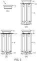
- FIG. 2 shows an example of such a process.
- a rotor 93 is mounted in the motor 1 in step (1) and then a stator 92 is positioned in the motor, with a separate shim 94 placed between the rotor 93 and the stator 92 at step (2).
- magnetic forces F attract the stator 92 towards the rotor 93 and the stator 92 is fixed into position by means of a fixation point 923.
- the shim 94 is removed at step (4), leaving an airgap 95.
- FIG 3 is a block diagram of a personal care device according to a general embodiment of an aspect of the invention.
- the personal care device 10 comprises a motor 1, according to embodiments of the present invention.
- the personal care device 10 may, for example be an oral care device, such as a power toothbrush, or may be a power shaver or a skin care device, such as a skin massager, or other type of personal care device.
- FIG 4 shows an exemplary personal care device in which the teaching of the present disclosure may be implemented.
- the personal care device in Figure 4 is in the form of an electric toothbrush (power toothbrush), but it will be appreciated that this is not limiting, and the teaching of the present disclosure may be implemented in other devices comprising a motor.
- the teachings may be applied to personal care devices such as tongue cleaners, shavers, hair clippers or trimmers, hair removal devices, or skin care devices.
- the personal care device 10 has an attachment structure 116 and a handle portion 112.
- the handle portion has a motor 1.
- the handle 112 may include a drive train 120 and a drive shaft 7.
- the drive shaft 7 extends from a distal end f the handle 112, and into the attachment structure 116 when an attachment structure 16 is attached to the handle 112.
- Motor 1 may comprise a motor controller (i.e., control electronics) which may be any suitable controller, microcontroller, processor, power source and/or other electronics to provide power and control signals for implementing the various functions, or any combination thereof, as discussed further herein.
- a motor controller i.e., control electronics
- control electronics may be any suitable controller, microcontroller, processor, power source and/or other electronics to provide power and control signals for implementing the various functions, or any combination thereof, as discussed further herein.
- motor 1 may be configured for providing and controlling an operation or operations of the drive train 120 to produce a mechanical stimulus.
- the mechanical stimulus may comprise vibrations or other movements at a high frequency, for example, a frequency greater than 50Hz, and for example a frequency in the range of 250-300Hz.
- the motor 1 may be a motor according to embodiments of the present invention.
- attachment structure 116 includes brush head 118.
- different types of attachment structures and devices can be used with different types of personal care devices 10 other than the electric toothbrush shown in the example in Figure 4 .
- the attachment structure 116 implements a motion.
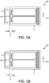
- Figures 5A and 5B show alternative arrangements according to a general embodiment of an aspect of the invention. Both figures show a motor 1 comprising a stator 2 and a rotor 3, with a spacer 4 disposed between them to define a minimum airgap 5.
- the motor 1a has a spacer 4a is disposed on a stator surface and is configured to engage (i.e. contact) with a surface of the rotor 3.
- the motor 1b in Figure 5B has a spacer 4b disposed on a rotor surface and is configured to engage (i.e. contact) with a surface of the stator 2.
- the spacer 4 defines a minimum distance between the rotor 3 and the stator 2, corresponding to a desired airgap.
- the defined airgap 5 is maintained by the spacer 4, such that the minimum size of the airgap 5 is determined by the size of the spacer 4 in the y-direction.
- a contact surface of the spacer 4 is configured to engage with or contact the rotor surface or the stator surface. However, it is also possible for there to be no contact between the contact surface of the spacer and the stator surface or the rotor surface, such that the spacer 4 is disposed on or at one of the rotor surface and the stator surface, and is separated from the other one of the rotor surface and the stator surface.
- the spacer may be disposed on the stator surface and configured to engage with the rotor surface, yet may not actually engage with or contact the rotor surface and a gap may be provided between the spacer and the rotor.
- the spacer may be disposed on the rotor surface and configured to engage with the stator surface, yet may not actually engage with or contact the stator surface and a gap may be provided between the spacer and the stator.
- the spacer is therefore still provided to prevent closure of the airgap but, since it is not initially contacting the rotor surface or stator surface, may be considered as a 'back-up' in the event of the rotor and stator moving towards each other due to, for example, failure/creep of parts or fixings, or an impact on the motor due to, for example, dropping of the device.
- FIG. 6 shows a method of manufacturing the motor according to a general embodiment of an aspect of the present invention.
- the rotor 3 is mounted in the motor.
- the stator 2 is positioned in the motor in step (2).
- a magnetic force F between the rotor 3 and the stator 2 causes the stator 2 and rotor 3 to be brought together at an interface area, at which the spacer 4a is disposed between the stator 2 and the rotor 3.
- the spacer 4a therefore prevents the stator 2 and the rotor 3 coming into direct contact, at any point other than at a contact region of the spacer 4a.
- the stator 2 is fixed into position in the motor at a fixation point 41. Any suitable fixation means may be used, such as, for example, screws or bolts. It may be seen from the method of manufacturing that means for setting the airgap is explicitly present in the motor itself and is provided by the spacer.
- the spacer 4a is disposed on the stator 2 in the arrangement shown in Figure 6 .
- the spacer may alternatively be disposed on the rotor 3.
- the method of manufacturing the motor is the same for both arrangements.
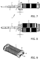
- Figure 7 is a side view of a drivetrain comprising the motor according to an embodiment of an aspect of the invention.
- the drivetrain comprises an output shaft 7 and a motor 1, which includes a rotor 3, a stator 2 and a spacer 4 disposed between the rotor 3 and the stator 2 to define a minimum airgap 5.
- the drivetrain may comprise further elements which are not required for the understanding of embodiments of the present invention and so are not included in the figures.
- a rotation axis 6 of the rotor 3, about which the rotor 3 may rotate, is aligned with the spacer 4.
- the output shaft 7 of the drivetrain is also aligned with the rotation axis 6. This may also be seen in Figure 8 which is a top view of the drivetrain shown in Figure 7 . Alignment of the spacer projection 4 with the rotation axis 6 may minimize the contact area between the spacer 4 and the surface of the rotor 3 or stator 2, and also reduce the friction between the spacer 4 and surfaces of the rotor 3 or stator 2.
- FIG 9 is a perspective view of a stator 2 according to an embodiment of an aspect of the invention.
- the stator 2 may be the stator 2 shown in the drivetrain of Figures 7 and 8 .
- the stator 2 comprises two iron cores each comprised of a plurality of laminations 8. Windings are provided around each core to provide two coils.
- a spacer 4a is disposed on the stator surface 22 such that it projects from the stator surface 22.
- the ends of the laminations 8 may also project from the end surface of the stator but the projection of the ends of the laminations is not as large as that of the spacer 4a (i.e.
- the airgap is generally defined as the distance between the stator and the rotor. If the stator is provided with laminations and the ends of these laminations project from the end surface of the stator, then the airgap may be defined as the distance between the ends of the laminations and the rotor (for example, a magnet of the rotor), i.e. the airgap is the shortest distance between components of the stator and components of the rotor (other than the spacer).
- the spacer 4a has a circular top shape at the contact surface, in order to minimise the contact area between the spacer and the rotor. Furthermore, the spacer 4a may be made out of a material which is both wear resistant and has low coefficient of friction, in order to further reduce the friction between the spacer 4a and the rotor surface. The working principle of the drivetrain is not affected by the presence of the spacer 4a.
- stator surface 22 is the end of the stator body, which may be a bobbin which holds the two cores, and the spacer 4a is formed on the end of the bobbin.
- stator surface may vary depending on the configuration of the stator and the formation or positioning of the spacer may also vary.
- FIG 10 is a perspective view of a rotor 3 according to an embodiment of an aspect of the invention.
- the rotor 3 may be the rotor 3 shown in the drivetrain of Figures 7 and 8 .
- the rotor 3 comprises a magnet 31 and an output shaft 7 of the drivetrain is connected to the rotor 3.
- the rotor 3 and the shaft 7 rotate about a rotation axis 6, such that the rotation axis 6 runs through the length of the output shaft 7.
- the rotor surface 32 is provided as a surface of the magnet 31 and the spacer is not disposed on the rotor surface.
- the spacer will be disposed on the stator surface and the contact surface of the spacer will engage with and contact the rotor surface 32 (the surface of the magnet 31).
- the spacer may preferably contact the rotor surface 32 at a center point which is aligned with the rotation axis 6 of the rotor 3, such that the spacer coincides with the axis of rotation.
- FIG 11 is an end view of a motor 1 according to an embodiment of an aspect of the invention.
- This motor may be the motor shown in Figures 7 and 8 and may utilise the stator shown in Figure 9 and the rotor shown in Figure 10 .
- the ends of the laminations 8 are shown either side of the rotation axis 6 and the magnet 32 of the rotor comprises a north N and south S pole.
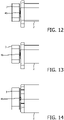
- Figure 12 is a side view of a motor according to an embodiment of an aspect of the invention.
- the spacer 4b is disposed on the rotor 3, and is configured to engage with the stator 2.
- the rotor 3 may be provided with a magnet and the spacer 4b may be disposed on a surface of the magnet which provides the rotor surface.
- Figures 13 and 14 show views of another embodiment in which the spacer 4b is provided on the rotor surface of the rotor 3. It may be seen that the spacer is aligned with the rotation axis of the rotor 3.
- FIG 15 is a perspective view of an arrangement of the stator according to an embodiment of an aspect of the invention.
- the stator 2 comprises a ball bearing 41a disposed on the stator surface 22 of the stator 2.
- the ball bearing 41a provides the spacer such that a surface of the ball bearing 41a is the contact surface configured to engage with a surface of the rotor, such as, for example a magnet surface.
- the ball bearing 41a is arranged in a collar or socket of the stator 2.
- the ball bearing 41a sits within the collar/socket and freely rotates with respect to the stator 2 and the rotor. Friction between the ball bearing 41a, stator 2 and rotor may therefore be reduced.
- FIGS 16A and 16B show a perspective view of an arrangement of the stator according to an embodiment of an aspect of the invention.
- the spacer 42a is provided on a plate which is configured to connect to the stator surface 22 of the stator 2 and, more specifically, with the ends of the laminations 8 of the stator 2. That is, the plate comprising the spacer 42a is installed directly onto the lamination ends 8.
- the stator surface 22 may be seen as being made up of the lamination ends 8 and the body of the stator 2 (for example, the bobbin).
- the spacer 42a may be considered as a bearing centrally located in the plate which is configured to engage with the lamination ends 8.
- the plate may be attached to the stator using any suitable fixation means, such as, for example, adhesive.
- the ends of the laminations may protrude slightly from the stator body in order for the plate to be attached, however, the protrusion will not be as large as the protrusion of the spacer 42a from the plate.
- the plate may be a stamped, non-ferrous (for example, brass) part located on the end face of the laminations, allowing for tight tolerance control in the y-direction.
- the plate may not contact the stator body, such that the plate may span across, as a simply supported beam, the two ends of the laminations and bridge the stator body between the lamination ends.
- the material of the plate must be stiff enough to support a thrust load without deforming.
- the spacer 42a (bearing point) is just proud of the lamination face.
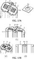
- FIGS 17A and 17B show an arrangement of the stator and spacer element according to an embodiment of an aspect of the invention.
- the spacer 43a is provided on a plate which is configured to connect to the stator surface 22 and, more specifically, to a recess provided in the stator body. That is, the stator surface 22 is shaped to receive and retain a plate comprising the spacer 43a. The plate may be retained in the recess by crush ribs or snaps 24 located at the outer edge of the recess.
- the recess comprises a step 81 on each of the lamination ends 8, upon which the plate sits when retained in the recess.
- the stator surface 22 may be seen as being made up of the body of the stator 2 (for example, the bobbin) and the stepped ends of the laminations 81.
- the step 81 on each of the lamination ends is provided with tight tolerance control.
- the plate may be a stamped, non-ferrous (for example, brass) part located on the step 81, allowing tight tolerance control in the y-direction.
- the spacer 43a (bearing point) is just proud of the lamination face.
- Diagram (3) in Figure 17B shows that the lamination ends 8 protrude above the level of the body of the stator, and the spacer 43a by a greater amount above the surface. Crush ribs or snaps are added to the recess to retain the plate, which minimises vibration and noise.
- FIGs 18A to 18C show a perspective view of an arrangement of the stator according to an embodiment of an aspect of the invention.
- the spacer 44a is provided as a part retained in the end of the stator body by a collar.
- the stator surface 22 is shaped to receive and retain the spacer part 44a.
- the spacer part 44a is shaped to engage with the stator surface 22 such that the spacer 44a is retained in the stator 2.
- the ends of the laminations 8 are each provided with a step 81 to receive the stator body, and allow for a thicker part of the stator body surrounding the spacer 44a so that the spacer 44a is securely retained.
- the stator surface 22 may be seen as the body of the stator 2 (for example, the bobbin).
- the step 81 on each of the lamination ends is provided with tight tolerance control.
- the stator body for example, bobbin
- the spacer part may be a screw-machined, non-ferrous (for example, brass) part which provides the spacer (bearing point) and is assembled between the stator body, which may comprise two complementary bobbins (bobbin halves).
- the spacer 44a (bearing point) is just proud of the lamination face.
- FIGS 19A to 19C show a perspective view of an arrangement of the stator according to an example not covered by the invention.
- the spacer 45a is provided on the stator surface 22 and, more specifically, is moulded in the stator body.
- the stator body may be a bobbin and the spacer 45a may be formed as part of the bobbin such that is projects from a surface of the bobbin.
- the stator surface 22 may be seen as the surface of the stator body, i.e. the bobbin surface.
- the ends of the laminations 8 are each provided with a step 81 to receive the stator body, and to improve tolerances.
- the spacer 45a is formed from the same material as the stator body (bobbin) and so suitable materials for the stator body are therefore also used to provide the spacer 45a. This arrangement does not require any additional parts and so is a low cost arrangement.
- the step 81 on each of the lamination ends is provided with tight tolerance control.
- the stator body for example, bobbin
- the spacer 45a is moulded into the bobbin.
- the spacer 45a (bearing point) is just proud of the lamination face.
- FIGS 20A to 20C show an arrangement of the stator according to an embodiment of an aspect of the invention.
- the spacer 46a is provided on a strap which is configured to connect to the stator surface 22 and, more specifically, to a recess provided in the stator body. That is, the stator surface 22 is shaped to receive and retain a strap comprising the spacer 46a.
- the ends of the strap are curved to engage with the ends of the stator body such that the ends of the strap may wrap around the edge of the stator body and the strap may be retained in the recess.
- the ends of the laminations 8 are each provided with a step 81 to receive the stator body, and allow for a part of the stator body to be present underneath the strap so that the spacer 44a may be securely retained.
- the stator surface 22 may be seen as the body of the stator 2 (for example, the bobbin).
- the step 81 on each of the lamination ends is provided with tight tolerance control.
- the stator body for example, bobbin
- the strap may be a stamped, non-ferrous (for example, brass) part disposed on the stator surface and assembled between the stator body, which may comprise two complementary bobbins (bobbin halves).
- the spacer 46a (bearing point) is just proud of the lamination face.
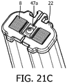
- FIGS 21A to 21C show an arrangement of the stator and spacer element according to an embodiment of an aspect of the invention.
- the spacer 47a is provided on a plate which is configured to connect to the stator surface 22 and, more specifically, to a recess provided in the stator body. That is, the stator surface 22 is shaped to receive and retain a plate comprising the spacer 47a.
- One or more shims 60 may be provided under the spacer plate to achieve the desired protrusion height of the spacer 47a.
- the stator body may comprise arms to retain the spacer plate in the recess.
- the stator surface 22 may be seen as the body of the stator 2 (for example, the bobbin).
- the stator body (bobbin) is shaped to receive and secure the spacer plate.
- the plate may be a stamped, non-ferrous (for example, brass) sheet disposed on the stator surface 22 and assembled between the stator body, which may comprise two complementary bobbins (bobbin halves).
- Shims 60 may be provided between the stator body and the spacer 47a to raise the spacer 47a (bearing point) so that it is just proud of the lamination face.
- FIGs 22A and 22B show an arrangement of the stator and spacer element according to an example not covered by the invention.
- the spacer 48a is provided on a strip which is configured to connect to the stator surface 22 and, more specifically, to a channel provided in the stator body and the laminations 8. That is, the stator surface 22 and the lamination cores 8 are shaped to receive and retain a strip comprising the spacer 48a.
- the channel in the stator body runs between the two laminated cores 8 and a shortened lamination 82 is provided in each core 8. The shortened laminations are aligned with the channel in the stator body such that the channel continues through the laminated cores 8.
- the height of the body of the strip corresponds to the depth of the channel in the laminated cores 8, such that the top edge of the strip is flush with the ends of the laminations 8 (other than the shortened laminations 82) when the strip is retained in the channel.
- the spacer 48a projects from the top edge of the strip and is located between the two laminated cores 8.
- the strip of this arrangement may be made of one of a number of different materials thus providing more material options.
- the shortened laminations 82 may be centrally located in their respective cores 8.
- the plate may be a stamped, non-ferrous (for example, brass) sheet disposed in the channel, on top of the shortened laminations 82, ensuring good y-direction tolerance control.
- the spacer 48a (bearing point) is just proud of the lamination face.
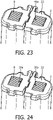
- FIG 23 is a perspective view of a stator according to an example not covered by the invention.
- the spacer 49a is provided as a protrusion extending from the end of one of the laminations in the laminated core 8.
- the stator surface 22 in this arrangement may be seen as the end of the laminated core 8.
- One or more of the laminations of the laminated core 8, such as the center lamination, are replaced by a lamination that includes a protrusion that provides the spacer 49a. Since the projection is provided on a lamination of the core, several material options are available. No further parts are required and so this is a low cost arrangement. Y-direction tolerances are controlled by the tight tolerances of the spacer 49a (bearing) lamination stamping.
- the spacer 49a lamination may be a ferrous or non-ferrous material, with a balance of bearing properties and magnetic properties.
- the spacer 49a (bearing point) is just proud of the lamination face.
- FIG 24 is a perspective view of an arrangement of the stator according to an example not covered by the invention.
- This arrangement is the same as the arrangement in Figure 23 , except a lamination with a projection is provided in each of the two cores 8, so as to provide two spacers 50a.
- one or more of the laminations of each of the laminated cores, such as the center lamination are replaced by a lamination that includes a protrusion that acts as a spacer 50a at each core end.
- the stator surface in this arrangement may be seen as comprising both ends of the laminated cores 8.
- each spacer 50a (bearing) lamination may be a ferrous or non-ferrous material, with a balance of bearing properties and magnetic properties.
- Each spacer 50a (bearing point) is just proud of the lamination face.
- embodiments of the present invention may prevent airgap closure by explicitly setting the minimum airgap with a spacer projecting between the stator and the rotor. Furthermore, the requirement for a shimming procedure during assembly may be avoided.
- the spacer may prevent the magnets of the rotor and coils of the stator from moving closer together.
- the spacer may set the airgap during assembly and control the airgap during its lifetime. For example, if the stator or rotor are not properly fixed, the spacer prevents the airgap from closing by providing a projection between the stator and rotor. It may therefore be seen as fall-back scenario to prevent the airgap from closing completely.
Landscapes
- Engineering & Computer Science (AREA)
- Power Engineering (AREA)
- Health & Medical Sciences (AREA)
- Dentistry (AREA)
- Epidemiology (AREA)
- Life Sciences & Earth Sciences (AREA)
- Animal Behavior & Ethology (AREA)
- General Health & Medical Sciences (AREA)
- Public Health (AREA)
- Veterinary Medicine (AREA)
- Iron Core Of Rotating Electric Machines (AREA)
- Brushes (AREA)
- Mounting Of Bearings Or Others (AREA)
- Motor Or Generator Frames (AREA)
- Massaging Devices (AREA)
- Telephone Function (AREA)
Claims (12)
- Un moteur (1) pour un dispositif de soins personnels (10), le moteur (1) comprend:un stator (2) comprenant une surface de stator;un rotor (3) comprend une surface de rotor, où le stator (2) est adjacent au rotor (3) dans une direction y de telle sorte que la surface de rotor est située à l'opposé de la surface de stator dans la direction y, où l'interaction entre le champ magnétique à partir du stator (2) et du rotor (3) provoque une torsion dans la direction y; et une entretoise (4) faisant saillie entre la surface du stator et la surface du rotor comme pour définir un écart d'air minimum (5) entre le stator (2) et le rotor (3) dans la direction y, où l'entretoise (4) est située sur ou à l'une des surfaces du rotor et la surface du stator,est caractérisée par le fait que l'entretoise possède une surface de contact incurvé configuré pour s'engager avec l'autre surface du rotor et la surface du stator, l'autre surface étant une surface plane.
- Le moteur (1) selon la revendication 1, où le rotor (3) est configuré pour tourner au moins partiellement autour d'un axe de rotation (6),
par rapport au stator (2); et l'entretoise (4) est alignée avec l'axe de rotation (6). - Le moteur (1) selon la revendication 1 ou 2, où l'entretoise (4) est au moins partiellement formée à partir d'un ou plusieurs éléments suivants:un matériau résistant à l'usure;un matériau à faible coefficient de frottement; etun matériau résistant au choc.
- Le moteur (1) selon l'une quelconque des revendications précédentes, où l'entretoise (4) est formée sur ou au niveau du stator ou connecté à celui-ci (2) de façon à ce que l'entretoise (4) dépasse d'au moins une partie de la surface du stator.
- Le moteur (1) selon l'une quelconque des revendications précédentes, où la surface du stator est configurée pour recevoir une plaque comprenant une entretoise (4).
- Le moteur (1) selon l'une quelconque des revendications précédentes comprend:
un roulement à billes (41a) configuré pour au moins tourner partiellement par rapport au rotor (3) et le stator (2), où l'entretoise (4) représente le roulement à billes (41a). - Le moteur (1) selon l'une quelconque des revendications précédentes 1 à 4, oùle stator (2) comprend un noyau formé d'une pluralité de stratifications (8);l'entretoise (4) est une saillie (49a; 50a) s'étendant à partir d'au moins une des extrémités des stratifications (8) du noyau.
- Le moteur (1) selon l'une quelconque des revendications précédentes, où au moins une partie de la surface du rotor possède un revêtement à faible friction.
- Le moteur (1) selon l'une quelconque des revendications précédentes, où au moins une partie de la surface du stator possède un revêtement à faible friction.
- Le moteur (1) selon l'une quelconque des revendications précédentes, où le rotor (3) comprend un aimant (31) qui possède une surface aimantée, la surface aimantée fournissant une surface au rotor.
- Un dispositif de soins personnels (10) comprend un moteur (1) selon l'une quelconque des revendications 1 à 10.
- Une méthode de fabrication d'un moteur (1) pour un dispositif de soins personnels (10), la méthode comprend:le montage d'un moteur (3) comprenant une surface de rotor dans le moteur (1);le placement d'un stator (2) comprenant la surface d'un stator dans le moteur (1) adjacent au rotor (1) dans une direction y de telle sorte que la surface du rotor est à l'opposé de la surface de stator dans la direction y; et une entretoise (4), situé sur ou à l'une des surfaces du rotor et la surface du stator,faisant saillie entre la surface de stator et une surface de rotor de manière à définir un intervalle d'air minimum (5) entre le stator (2) et le rotor (3) dans la direction y;caractérisé par le fait que la méthode comprend:
le déplacement du stator (2) vers le rotor (2) de telle sorte que la surface de contact incurvée de l'entretoise (4) s'engage avec une des surfaces du rotor et la surface du stator, l'autre surface étant une surface plane; etla fixation du stator (2) dans le moteur (1).
Applications Claiming Priority (2)
| Application Number | Priority Date | Filing Date | Title |
|---|---|---|---|
| US201862657248P | 2018-04-13 | 2018-04-13 | |
| PCT/EP2019/059489 WO2019197643A1 (fr) | 2018-04-13 | 2019-04-12 | Moteur pour dispositif de soins personnels |
Publications (2)
| Publication Number | Publication Date |
|---|---|
| EP3776824A1 EP3776824A1 (fr) | 2021-02-17 |
| EP3776824B1 true EP3776824B1 (fr) | 2022-09-14 |
Family
ID=66223710
Family Applications (1)
| Application Number | Title | Priority Date | Filing Date |
|---|---|---|---|
| EP19718315.5A Active EP3776824B1 (fr) | 2018-04-13 | 2019-04-12 | Moteur pour dispositif de soins personnels |
Country Status (6)
| Country | Link |
|---|---|
| US (2) | US11843294B2 (fr) |
| EP (1) | EP3776824B1 (fr) |
| JP (1) | JP2021521765A (fr) |
| CN (1) | CN112189298A (fr) |
| ES (1) | ES2930334T3 (fr) |
| WO (1) | WO2019197643A1 (fr) |
Families Citing this family (1)
| Publication number | Priority date | Publication date | Assignee | Title |
|---|---|---|---|---|
| CN113708588B (zh) * | 2021-08-18 | 2023-06-02 | 深圳市力博得科技有限公司 | 振动电机 |
Citations (1)
| Publication number | Priority date | Publication date | Assignee | Title |
|---|---|---|---|---|
| US6054786A (en) * | 1999-05-27 | 2000-04-25 | Halo Data Devices, Inc. | Method and system for providing a spherical bearing in a thin film reluctance motor |
Family Cites Families (17)
| Publication number | Priority date | Publication date | Assignee | Title |
|---|---|---|---|---|
| US2196667A (en) | 1937-12-13 | 1940-04-09 | Motodent Inc | Electric toothbrush |
| US2917758A (en) * | 1956-02-21 | 1959-12-22 | Aesup | Electrically controlled tooth-brush |
| JP3936538B2 (ja) * | 2000-05-30 | 2007-06-27 | 株式会社Neomax | 薄型永久磁石式発電機及びそれを組み込んだディスケット |
| JP3638553B2 (ja) * | 2001-12-10 | 2005-04-13 | 日本電産コパル株式会社 | ブラシレスモータ |
| JP4155101B2 (ja) * | 2003-05-16 | 2008-09-24 | 松下電工株式会社 | 振動型リニアアクチュエータ及びそれを用いた電動歯ブラシ |
| WO2007148783A1 (fr) * | 2006-06-22 | 2007-12-27 | Nidec Corporation | Structure de coussinet d'arbre et moteur de vibration utilisant la structure de coussinet |
| JP2011516021A (ja) * | 2008-03-28 | 2011-05-19 | ベク,ミョンーホ | ブラシレス振動モータ |
| JP5251265B2 (ja) | 2008-06-02 | 2013-07-31 | オムロンヘルスケア株式会社 | 電動歯ブラシ |
| IT1399082B1 (it) * | 2010-03-25 | 2013-04-05 | Claudio Lastrucci | Sistema di conversione elettro-meccanica a magnete mobile; diffusore acustico comprendente detto sistema ed un organo mobile di generazione di onde acustiche. |
| KR20120068801A (ko) * | 2012-05-29 | 2012-06-27 | 나향옥 | 충격진동 발생장치 및 그 응용장치 |
| ES2693620T3 (es) * | 2012-07-13 | 2018-12-13 | Braun Gmbh | Motor lineal y dispositivo eléctrico con motor lineal |
| US9973049B2 (en) * | 2013-03-15 | 2018-05-15 | Techtronic Industries Co. Ltd. | Electric motor |
| US9757220B2 (en) | 2014-04-16 | 2017-09-12 | Koninklijke Philips N.V. | Multifunction modular motor mount bumper |
| WO2015159162A1 (fr) | 2014-04-16 | 2015-10-22 | Koninklijke Philips N.V. | Système de montage de moteur en suspension dans une brosse à dents électrique |
| JP6616336B2 (ja) * | 2014-06-17 | 2019-12-04 | コーニンクレッカ フィリップス エヌ ヴェ | パーソナルケア器具のための駆動システム及びパーソナルケア器具の動作方法 |
| JP6731205B2 (ja) * | 2015-08-03 | 2020-07-29 | 日本電産コパル株式会社 | 振動モータ |
| GB201518387D0 (en) * | 2015-10-16 | 2015-12-02 | Yasa Motors Ltd | Axial flux machine |
-
2019
- 2019-04-12 US US17/046,817 patent/US11843294B2/en active Active
- 2019-04-12 JP JP2020555878A patent/JP2021521765A/ja active Pending
- 2019-04-12 WO PCT/EP2019/059489 patent/WO2019197643A1/fr active Application Filing
- 2019-04-12 CN CN201980034971.9A patent/CN112189298A/zh active Pending
- 2019-04-12 ES ES19718315T patent/ES2930334T3/es active Active
- 2019-04-12 EP EP19718315.5A patent/EP3776824B1/fr active Active
-
2023
- 2023-11-28 US US18/521,040 patent/US20240097541A1/en active Pending
Patent Citations (1)
| Publication number | Priority date | Publication date | Assignee | Title |
|---|---|---|---|---|
| US6054786A (en) * | 1999-05-27 | 2000-04-25 | Halo Data Devices, Inc. | Method and system for providing a spherical bearing in a thin film reluctance motor |
Also Published As
| Publication number | Publication date |
|---|---|
| CN112189298A (zh) | 2021-01-05 |
| WO2019197643A1 (fr) | 2019-10-17 |
| ES2930334T3 (es) | 2022-12-12 |
| US20240097541A1 (en) | 2024-03-21 |
| US20210152066A1 (en) | 2021-05-20 |
| JP2021521765A (ja) | 2021-08-26 |
| EP3776824A1 (fr) | 2021-02-17 |
| US11843294B2 (en) | 2023-12-12 |
Similar Documents
| Publication | Publication Date | Title |
|---|---|---|
| US10033258B2 (en) | Linear actuator, electric brush, electric cutting machine and electric air pump | |
| US20240097541A1 (en) | Motor for a personal care device | |
| CN108933495B (zh) | 马达 | |
| US7965000B2 (en) | Vibratory linear actuator | |
| US7607229B2 (en) | Electric razor | |
| CN109256887B (zh) | 马达 | |
| JP7022617B2 (ja) | 振動アクチュエータ | |
| CN107070308B (zh) | 一种磁悬浮振动电机 | |
| US10855154B2 (en) | Actuator and electric beautifying device | |
| RU2784415C2 (ru) | Двигатель для устройства для личной гигиены | |
| WO2022209908A1 (fr) | Actionneur de vibration | |
| CN113472106A (zh) | 转子和马达 | |
| CN108933496B (zh) | 马达 | |
| JP2021176637A (ja) | 振動アクチュエータ | |
| JP2000354359A (ja) | Pm形ステッピングモータ | |
| JP2002177665A (ja) | 往復式電気かみそり | |
| CN211280118U (zh) | 扭杆组件、电雕头及电雕制版设备 | |
| JP7329985B2 (ja) | 回転電機及びその端板 | |
| JP3433571B2 (ja) | 往復式電気かみそり | |
| KR101097684B1 (ko) | 스텝핑 모터 | |
| JP6049501B2 (ja) | 電磁アクチュエータ | |
| JP3382057B2 (ja) | リニアアクチュエータ | |
| JPH10341551A (ja) | 小型モータ | |
| KR20040108531A (ko) | 편평형 모터의 전기자 구조 | |
| KR20050029360A (ko) | 스핀들 모터 |
Legal Events
| Date | Code | Title | Description |
|---|---|---|---|
| STAA | Information on the status of an ep patent application or granted ep patent |
Free format text: STATUS: UNKNOWN |
|
| STAA | Information on the status of an ep patent application or granted ep patent |
Free format text: STATUS: THE INTERNATIONAL PUBLICATION HAS BEEN MADE |
|
| PUAI | Public reference made under article 153(3) epc to a published international application that has entered the european phase |
Free format text: ORIGINAL CODE: 0009012 |
|
| STAA | Information on the status of an ep patent application or granted ep patent |
Free format text: STATUS: REQUEST FOR EXAMINATION WAS MADE |
|
| 17P | Request for examination filed |
Effective date: 20201113 |
|
| AK | Designated contracting states |
Kind code of ref document: A1 Designated state(s): AL AT BE BG CH CY CZ DE DK EE ES FI FR GB GR HR HU IE IS IT LI LT LU LV MC MK MT NL NO PL PT RO RS SE SI SK SM TR |
|
| AX | Request for extension of the european patent |
Extension state: BA ME |
|
| DAV | Request for validation of the european patent (deleted) | ||
| DAX | Request for extension of the european patent (deleted) | ||
| GRAP | Despatch of communication of intention to grant a patent |
Free format text: ORIGINAL CODE: EPIDOSNIGR1 |
|
| STAA | Information on the status of an ep patent application or granted ep patent |
Free format text: STATUS: GRANT OF PATENT IS INTENDED |
|
| INTG | Intention to grant announced |
Effective date: 20220406 |
|
| GRAJ | Information related to disapproval of communication of intention to grant by the applicant or resumption of examination proceedings by the epo deleted |
Free format text: ORIGINAL CODE: EPIDOSDIGR1 |
|
| GRAS | Grant fee paid |
Free format text: ORIGINAL CODE: EPIDOSNIGR3 |
|
| GRAA | (expected) grant |
Free format text: ORIGINAL CODE: 0009210 |
|
| STAA | Information on the status of an ep patent application or granted ep patent |
Free format text: STATUS: THE PATENT HAS BEEN GRANTED |
|
| INTG | Intention to grant announced |
Effective date: 20220406 |
|
| AK | Designated contracting states |
Kind code of ref document: B1 Designated state(s): AL AT BE BG CH CY CZ DE DK EE ES FI FR GB GR HR HU IE IS IT LI LT LU LV MC MK MT NL NO PL PT RO RS SE SI SK SM TR |
|
| REG | Reference to a national code |
Ref country code: GB Ref legal event code: FG4D |
|
| REG | Reference to a national code |
Ref country code: CH Ref legal event code: EP |
|
| REG | Reference to a national code |
Ref country code: DE Ref legal event code: R096 Ref document number: 602019019581 Country of ref document: DE |
|
| REG | Reference to a national code |
Ref country code: IE Ref legal event code: FG4D |
|
| REG | Reference to a national code |
Ref country code: AT Ref legal event code: REF Ref document number: 1519299 Country of ref document: AT Kind code of ref document: T Effective date: 20221015 |
|
| REG | Reference to a national code |
Ref country code: ES Ref legal event code: FG2A Ref document number: 2930334 Country of ref document: ES Kind code of ref document: T3 Effective date: 20221212 |
|
| REG | Reference to a national code |
Ref country code: NL Ref legal event code: FP |
|
| REG | Reference to a national code |
Ref country code: LT Ref legal event code: MG9D |
|
| PG25 | Lapsed in a contracting state [announced via postgrant information from national office to epo] |
Ref country code: SE Free format text: LAPSE BECAUSE OF FAILURE TO SUBMIT A TRANSLATION OF THE DESCRIPTION OR TO PAY THE FEE WITHIN THE PRESCRIBED TIME-LIMIT Effective date: 20220914 Ref country code: RS Free format text: LAPSE BECAUSE OF FAILURE TO SUBMIT A TRANSLATION OF THE DESCRIPTION OR TO PAY THE FEE WITHIN THE PRESCRIBED TIME-LIMIT Effective date: 20220914 Ref country code: NO Free format text: LAPSE BECAUSE OF FAILURE TO SUBMIT A TRANSLATION OF THE DESCRIPTION OR TO PAY THE FEE WITHIN THE PRESCRIBED TIME-LIMIT Effective date: 20221214 Ref country code: LV Free format text: LAPSE BECAUSE OF FAILURE TO SUBMIT A TRANSLATION OF THE DESCRIPTION OR TO PAY THE FEE WITHIN THE PRESCRIBED TIME-LIMIT Effective date: 20220914 Ref country code: LT Free format text: LAPSE BECAUSE OF FAILURE TO SUBMIT A TRANSLATION OF THE DESCRIPTION OR TO PAY THE FEE WITHIN THE PRESCRIBED TIME-LIMIT Effective date: 20220914 Ref country code: FI Free format text: LAPSE BECAUSE OF FAILURE TO SUBMIT A TRANSLATION OF THE DESCRIPTION OR TO PAY THE FEE WITHIN THE PRESCRIBED TIME-LIMIT Effective date: 20220914 |
|
| REG | Reference to a national code |
Ref country code: AT Ref legal event code: MK05 Ref document number: 1519299 Country of ref document: AT Kind code of ref document: T Effective date: 20220914 |
|
| PG25 | Lapsed in a contracting state [announced via postgrant information from national office to epo] |
Ref country code: HR Free format text: LAPSE BECAUSE OF FAILURE TO SUBMIT A TRANSLATION OF THE DESCRIPTION OR TO PAY THE FEE WITHIN THE PRESCRIBED TIME-LIMIT Effective date: 20220914 Ref country code: GR Free format text: LAPSE BECAUSE OF FAILURE TO SUBMIT A TRANSLATION OF THE DESCRIPTION OR TO PAY THE FEE WITHIN THE PRESCRIBED TIME-LIMIT Effective date: 20221215 |
|
| PG25 | Lapsed in a contracting state [announced via postgrant information from national office to epo] |
Ref country code: SM Free format text: LAPSE BECAUSE OF FAILURE TO SUBMIT A TRANSLATION OF THE DESCRIPTION OR TO PAY THE FEE WITHIN THE PRESCRIBED TIME-LIMIT Effective date: 20220914 Ref country code: RO Free format text: LAPSE BECAUSE OF FAILURE TO SUBMIT A TRANSLATION OF THE DESCRIPTION OR TO PAY THE FEE WITHIN THE PRESCRIBED TIME-LIMIT Effective date: 20220914 Ref country code: PT Free format text: LAPSE BECAUSE OF FAILURE TO SUBMIT A TRANSLATION OF THE DESCRIPTION OR TO PAY THE FEE WITHIN THE PRESCRIBED TIME-LIMIT Effective date: 20230116 Ref country code: CZ Free format text: LAPSE BECAUSE OF FAILURE TO SUBMIT A TRANSLATION OF THE DESCRIPTION OR TO PAY THE FEE WITHIN THE PRESCRIBED TIME-LIMIT Effective date: 20220914 Ref country code: AT Free format text: LAPSE BECAUSE OF FAILURE TO SUBMIT A TRANSLATION OF THE DESCRIPTION OR TO PAY THE FEE WITHIN THE PRESCRIBED TIME-LIMIT Effective date: 20220914 |
|
| PG25 | Lapsed in a contracting state [announced via postgrant information from national office to epo] |
Ref country code: SK Free format text: LAPSE BECAUSE OF FAILURE TO SUBMIT A TRANSLATION OF THE DESCRIPTION OR TO PAY THE FEE WITHIN THE PRESCRIBED TIME-LIMIT Effective date: 20220914 Ref country code: PL Free format text: LAPSE BECAUSE OF FAILURE TO SUBMIT A TRANSLATION OF THE DESCRIPTION OR TO PAY THE FEE WITHIN THE PRESCRIBED TIME-LIMIT Effective date: 20220914 Ref country code: IS Free format text: LAPSE BECAUSE OF FAILURE TO SUBMIT A TRANSLATION OF THE DESCRIPTION OR TO PAY THE FEE WITHIN THE PRESCRIBED TIME-LIMIT Effective date: 20230114 Ref country code: EE Free format text: LAPSE BECAUSE OF FAILURE TO SUBMIT A TRANSLATION OF THE DESCRIPTION OR TO PAY THE FEE WITHIN THE PRESCRIBED TIME-LIMIT Effective date: 20220914 |
|
| PGFP | Annual fee paid to national office [announced via postgrant information from national office to epo] |
Ref country code: TR Payment date: 20230329 Year of fee payment: 5 |
|
| REG | Reference to a national code |
Ref country code: DE Ref legal event code: R097 Ref document number: 602019019581 Country of ref document: DE |
|
| PG25 | Lapsed in a contracting state [announced via postgrant information from national office to epo] |
Ref country code: AL Free format text: LAPSE BECAUSE OF FAILURE TO SUBMIT A TRANSLATION OF THE DESCRIPTION OR TO PAY THE FEE WITHIN THE PRESCRIBED TIME-LIMIT Effective date: 20220914 |
|
| PLBE | No opposition filed within time limit |
Free format text: ORIGINAL CODE: 0009261 |
|
| STAA | Information on the status of an ep patent application or granted ep patent |
Free format text: STATUS: NO OPPOSITION FILED WITHIN TIME LIMIT |
|
| PG25 | Lapsed in a contracting state [announced via postgrant information from national office to epo] |
Ref country code: DK Free format text: LAPSE BECAUSE OF FAILURE TO SUBMIT A TRANSLATION OF THE DESCRIPTION OR TO PAY THE FEE WITHIN THE PRESCRIBED TIME-LIMIT Effective date: 20220914 |
|
| PGFP | Annual fee paid to national office [announced via postgrant information from national office to epo] |
Ref country code: IT Payment date: 20230421 Year of fee payment: 5 Ref country code: FR Payment date: 20230421 Year of fee payment: 5 Ref country code: ES Payment date: 20230515 Year of fee payment: 5 Ref country code: DE Payment date: 20230427 Year of fee payment: 5 |
|
| 26N | No opposition filed |
Effective date: 20230615 |
|
| PG25 | Lapsed in a contracting state [announced via postgrant information from national office to epo] |
Ref country code: SI Free format text: LAPSE BECAUSE OF FAILURE TO SUBMIT A TRANSLATION OF THE DESCRIPTION OR TO PAY THE FEE WITHIN THE PRESCRIBED TIME-LIMIT Effective date: 20220914 |
|
| PGFP | Annual fee paid to national office [announced via postgrant information from national office to epo] |
Ref country code: BE Payment date: 20230424 Year of fee payment: 5 |
|
| PGFP | Annual fee paid to national office [announced via postgrant information from national office to epo] |
Ref country code: GB Payment date: 20230418 Year of fee payment: 5 |
|
| REG | Reference to a national code |
Ref country code: CH Ref legal event code: PL |
|
| PG25 | Lapsed in a contracting state [announced via postgrant information from national office to epo] |
Ref country code: LU Free format text: LAPSE BECAUSE OF NON-PAYMENT OF DUE FEES Effective date: 20230412 |
|
| PG25 | Lapsed in a contracting state [announced via postgrant information from national office to epo] |
Ref country code: MC Free format text: LAPSE BECAUSE OF FAILURE TO SUBMIT A TRANSLATION OF THE DESCRIPTION OR TO PAY THE FEE WITHIN THE PRESCRIBED TIME-LIMIT Effective date: 20220914 |
|
| PG25 | Lapsed in a contracting state [announced via postgrant information from national office to epo] |
Ref country code: MC Free format text: LAPSE BECAUSE OF FAILURE TO SUBMIT A TRANSLATION OF THE DESCRIPTION OR TO PAY THE FEE WITHIN THE PRESCRIBED TIME-LIMIT Effective date: 20220914 Ref country code: LI Free format text: LAPSE BECAUSE OF NON-PAYMENT OF DUE FEES Effective date: 20230430 Ref country code: CH Free format text: LAPSE BECAUSE OF NON-PAYMENT OF DUE FEES Effective date: 20230430 |
|
| REG | Reference to a national code |
Ref country code: IE Ref legal event code: MM4A |
|
| PG25 | Lapsed in a contracting state [announced via postgrant information from national office to epo] |
Ref country code: IE Free format text: LAPSE BECAUSE OF NON-PAYMENT OF DUE FEES Effective date: 20230412 |
|
| PG25 | Lapsed in a contracting state [announced via postgrant information from national office to epo] |
Ref country code: IE Free format text: LAPSE BECAUSE OF NON-PAYMENT OF DUE FEES Effective date: 20230412 |
|
| PGFP | Annual fee paid to national office [announced via postgrant information from national office to epo] |
Ref country code: NL Payment date: 20240425 Year of fee payment: 6 |