EP3774506B1 - Dispositif automatisé pour panneaux de construction - Google Patents
Dispositif automatisé pour panneaux de construction Download PDFInfo
- Publication number
- EP3774506B1 EP3774506B1 EP19721660.9A EP19721660A EP3774506B1 EP 3774506 B1 EP3774506 B1 EP 3774506B1 EP 19721660 A EP19721660 A EP 19721660A EP 3774506 B1 EP3774506 B1 EP 3774506B1
- Authority
- EP
- European Patent Office
- Prior art keywords
- automated device
- tool
- chamber
- chambers
- suction
- Prior art date
- Legal status (The legal status is an assumption and is not a legal conclusion. Google has not performed a legal analysis and makes no representation as to the accuracy of the status listed.)
- Active
Links
Images



Classifications
-
- B—PERFORMING OPERATIONS; TRANSPORTING
- B62—LAND VEHICLES FOR TRAVELLING OTHERWISE THAN ON RAILS
- B62D—MOTOR VEHICLES; TRAILERS
- B62D57/00—Vehicles characterised by having other propulsion or other ground- engaging means than wheels or endless track, alone or in addition to wheels or endless track
- B62D57/02—Vehicles characterised by having other propulsion or other ground- engaging means than wheels or endless track, alone or in addition to wheels or endless track with ground-engaging propulsion means, e.g. walking members
- B62D57/024—Vehicles characterised by having other propulsion or other ground- engaging means than wheels or endless track, alone or in addition to wheels or endless track with ground-engaging propulsion means, e.g. walking members specially adapted for moving on inclined or vertical surfaces
-
- E—FIXED CONSTRUCTIONS
- E04—BUILDING
- E04F—FINISHING WORK ON BUILDINGS, e.g. STAIRS, FLOORS
- E04F21/00—Implements for finishing work on buildings
- E04F21/18—Implements for finishing work on buildings for setting wall or ceiling slabs or plates
- E04F21/1838—Implements for finishing work on buildings for setting wall or ceiling slabs or plates for setting a plurality of similar elements
- E04F21/1844—Implements for finishing work on buildings for setting wall or ceiling slabs or plates for setting a plurality of similar elements by applying them one by one
- E04F21/1872—Implements for finishing work on buildings for setting wall or ceiling slabs or plates for setting a plurality of similar elements by applying them one by one using suction-cups
-
- E—FIXED CONSTRUCTIONS
- E04—BUILDING
- E04G—SCAFFOLDING; FORMS; SHUTTERING; BUILDING IMPLEMENTS OR AIDS, OR THEIR USE; HANDLING BUILDING MATERIALS ON THE SITE; REPAIRING, BREAKING-UP OR OTHER WORK ON EXISTING BUILDINGS
- E04G21/00—Preparing, conveying, or working-up building materials or building elements in situ; Other devices or measures for constructional work
- E04G21/14—Conveying or assembling building elements
- E04G21/16—Tools or apparatus
Definitions
- the field of the present invention is that of automated devices used in the construction of buildings, and more particularly of robots capable of carrying out mechanical operations on supports used in the building such as construction panels.
- Construction panels are widely used in the construction industry, for example to make partitions, floors or ceilings, to cover such surfaces, to insulate them thermally and/or acoustically, to protect these surfaces from humidity, or even double these surfaces.
- the construction panels correspond to plates made of a material chosen according to its use.
- a framework serves as a support for fixing such construction panels to the walls and ceilings. This intervention requires carrying out several successive fixings of fixing means. These fasteners ensure that each construction panel is attached to the framework. For optimum fastening, on average twelve screws per square meter of building board are required. Thus, it is understood that for the production of an entire partition, this step of fixing the construction panels is particularly time-consuming for the technician in charge of this operation. This represents a first drawback of the technique known to date.
- the fixing tools usually used are often heavy, which adds an additional constraint for the technician.
- the fixing step can then become particularly difficult, especially when it comes to fixing a building panel to a ceiling or when it comes to fixing an upper part of the building panel located above the technician in charge of the operation. This represents a second drawback.
- the object of the present invention is to propose an automated device which corrects the drawbacks stated above and also to lead to other advantages.
- the invention achieves this through an automated device according to claim 1 and configured to move supported on a construction panel, the automated device comprising a frame carrying a tool, said tool being configured to perform at least one mechanical operation on the construction panel, the automated device comprising at least one suction member and at least one means for moving the automated device along the construction panel, the automated device comprising at least two chambers configured to hold the automated device against the construction panel, the tool being located between said at least two chambers.
- the present invention therefore aims to meet the constraints set out above by proposing a reliable automated device capable of moving easily on the construction panel, performing the mechanical operations usually devolved to the drywall technician.
- a reliable automated device capable of moving easily on the construction panel, performing the mechanical operations usually devolved to the drywall technician.
- Such an automated device according to the invention makes it possible to carry out these mechanical operations repetitively in complete safety on a construction panel covering a wall, a ceiling or a floor.
- Such an automated device is adapted to the adhesion and friction stresses inherent in any inclination of the surface on which it moves.
- This configuration according to the invention makes it possible to position the tool between the chambers of the automated device, and therefore to eliminate any offset of the tool with respect to the chambers.
- the tool no longer causes imbalance at the level of the automated device, thus favoring the adhesion of the automated device to the construction panel on which it rests, even when the tool generates a significant force while it implements mechanical operation.
- the tool is arranged between at least two chambers by being placed inside a single perimeter joining an outer edge of each chamber, such an edge being for example materialized by a sealing device.
- the tool is between the chambers and inside a polygon passing through an outer edge of the frame.
- construction panels comprising plaster, wood or wood particles, synthetic materials, mixed fibers, particles minerals, or a mixture of these materials, these construction panels also being able to be covered with a surface coating in a material different from the material chosen.
- the automated device comprises at least one electric suction motor and the at least one suction member comprises means for creating a depression, said means for creating a depression generating a depression at the level of said at least two chambers when rotated by said electric suction motor.
- the depression induced by the electric suction motor and the means for creating a depression generates a suction force at the level of the chambers of the automated device.
- the depressurization means comprise at least one propeller, the electric suction motor allowing said at least one propeller to rotate. The rotation of the propeller then generates a depression at the level of at least one chamber.
- the suction force generated by the suction member of the automated device is perpendicular to a general extension plane of the frame of the automated device, the frame of the automated device being the constituent element of the structure of said automated device. More particularly, the general extension plane of the chassis of the automated device is the largest plane along which the chassis of the automated device extends. This configuration makes it possible to press the automated device against the construction panel, regardless of the inclination of the construction panel.
- the electric suction motor is powered by an electrical power supply external to the automated device.
- the electric suction motor is powered by an electrical power supply integrated into the automated device.
- each suction member comprises at least one sealing device and a plate constituting the frame, the sealing device and the plate delimiting one of the chambers.
- the frame comprises at least two platforms, each platform comprising at least one plate, and a suction member.
- Each plate extends in a plane parallel to the general extension plane of the frame of the automated device. More particularly, each plate comprises an upper face and a lower face.
- the underside of a tray is oriented towards the construction panel when the automated device is resting against it.
- the upper face of the table is the face that faces the tool.
- the sealing device is located between the underside of the tray and the construction panel.
- each chamber defines a volume, said volume being delimited by the underside of the plate, by the sealing device and by a mouth of the sealing device intended to bear against the construction panel.
- each platform of the automated device supports a suction member.
- the suction member of a platform is then associated with the chamber which is delimited by this same platform.
- At least one chamber is also delimited by a sealing device, said sealing device being integral with the platform which delimits the chamber. More particularly, a first face of the sealing device bears against the platform of the automated device and a second face of the sealing device bears against the construction panel.
- This configuration makes it possible to limit or even eliminate air leaks between the chamber and the external environment, thus requiring a lower suction force to make the automated device adhere to the construction panel.
- the use of a lower suction force allows a reduction in the amount of energy required by the suction member to adhere the automated device to the building panel.
- This specific arrangement of the sealing device and of the platform also guarantees that the platform is supported against the construction panel, which contributes significantly to stabilizing the automated device when the tool is used.
- the platform comprises an orifice allowing communication between the chamber and an environment outside said chamber. This configuration makes it possible to limit or even eliminate the depression within the chamber.
- the platform also comprises an obturation element configured to partially or completely obturate the orifice of the platform.
- the closure element is a valve, a valve or a flap. This configuration allows a depression maximum within the chamber when the orifice of the platform is completely closed by the closing element. Conversely, the depression at the level of the chamber is weaker when the closure element does not completely close the orifice of the platform.
- the closure element of the orifice of the platform allows modulation of the level of depression within the chamber comprising such a closure element.
- the suction force required to adhere the automated device to the construction panel may vary, in particular depending on the angle of inclination of the construction panel with respect to a horizontal plane, or even if the automated device is suspended from a ceiling, or again depending on a counter-force exerted by the tool on the construction panel, said counter-force being exerted when the tool performs a mechanical operation on the construction panel.
- the suction force generated by the electric suction motor and the depression means may need to be modulated. More particularly, the modulation of the suction force at the level of a chamber can be obtained, for example, by a modulation of the speed of rotation of the propeller, or by the modulation of the opening of the element of closure of the platform.
- the suction member of the automated device comprises a single electric suction motor configured to generate a suction force at said at least two chambers. More particularly, the suction member comprises a single means for creating a vacuum cooperating with said at least two chambers. Alternatively, the suction member comprises a single electric suction motor and at least two means for creating a vacuum, said at least two means for creating a vacuum each cooperating with a separate chamber.
- the suction member of the automated device comprises at least two electric motors configured to generate a suction force at said at least two chambers, each electric suction motor cooperating with a separate chamber of 'an other room. More specifically, each electric suction motor cooperates with a separate depression means in order to generate a suction force at the level of a separate chamber from the other chamber. In other words, each electric suction motor is associated with a single chamber.
- said at least two chambers are regularly angularly arranged around the tool.
- the automated device comprises two chambers
- said two chambers are angularly spaced by 180° relative to each other.
- said three chambers are angularly spaced by 120° with respect to each other.
- said four chambers are angularly spaced by 90° relative to each other.
- each chamber extends around a central axis, the tool being arranged at an equal distance from the central axis of each chamber.
- the central axis of a chamber is defined by a straight line which extends perpendicularly to the general extension plane of the frame of the automated device, said straight line passing through the center of the chamber.
- the tool is then located at a central transverse plane of the automated device, the central transverse plane of the automated device being perpendicular to the general extension plane of the frame and located at an equal distance from the central axis of each chamber.
- the suction member is configured to exert an identical, or substantially identical, suction force at the level of each chamber, said chambers being arranged symmetrically with respect to the tool .
- Two suction forces will be considered identical if their difference in suction does not exceed 10% of the force of one of the suction forces.
- each chamber extends around a central axis, the tool being closer to the central axis of a first chamber than to the central axis of the second chamber.
- the tool is not located at the level of the central transverse plane of the automated device.
- the tool is offset relative to a central transverse plane, the central transverse plane being transverse relative to the longitudinal extension plane of the automated device.
- the suction member is configured to exert a suction force which compensates for an offset of the tool relative to the central transverse plane of the automated device.
- a greater suction force must be generated at the level of a suction chamber during a shift of the tool towards said suction chamber with respect to the central transverse plane of the automated device.
- the speed of rotation of the depressurization means cooperating with a chamber can be modulated in order to provide a greater or lesser suction force at the level of the chamber, said suction force being higher when the speed of rotation of said depressurizing means increases.
- Compensation for the tool positioning deviation can also be obtained by modulating the opening of the chamber orifice via the closing element, the closing of the chamber orifice generating a greater suction force.
- each platform comprises a passage, said passage allowing the vacuum device to generate a vacuum at the level of the chamber.
- the passage allows communication between the depressurization device and the chamber.
- the passage is positioned at the level of the central axis of the chamber.
- said at least two chambers and the tool are aligned along the same axis. More particularly, the two chambers and the tool are arranged rectilinearly relative to each other.
- the suction member is configured to exert a force, said force being greater than the force exerted by the weight of the automated device.
- This configuration allows the automated device to be pressed against the building panel. More particularly, the sum of the suction forces exerted at said at least two chambers is greater than the sum of the force exerted by the weight of the automated device and the force exerted by the tool on the construction panel.
- the tool performs a mechanical operation on the construction panel
- the tool exerts a force on the construction panel, said force in turn inducing a counter-force of identical value and opposite direction.
- the counter-force exerted by the tool on the construction panel is added to the force exerted by the weight of the automated device.
- This configuration allows the automated device to be pressed against the construction panel even when the tool performs a mechanical operation on the construction panel.
- At least one platform supports the at least one means for moving the automated device.
- the means for moving the automated device bear against the construction panel when the automated device adheres to said construction panel.
- the at least one moving means comprises at least one wheel and an electric motor for driving the wheel.
- the means for setting the automated device in motion are supported by at least two separate platforms. This configuration makes it possible to grant greater stability to the automated device on the building panel.
- the mechanical operation carried out by the tool corresponds to an operation of fixing, cutting or sanding the construction panel.
- the fixing of the construction panel to the frame can be done using screws, staples or nails, the tool then being a fixing tool, in particular a screwdriver, a stapler or a nail gun, respectively.
- the construction panel can be cut using a hole saw, a jigsaw or even a blade, the tool then being respectively a hole saw, a jigsaw, or a blade.
- the sanding of the construction panel can be done using abrasive sheets, the tool being configured to cause a movement of translation or rotation of the abrasive sheets against the construction panel, the tool then being a sander.
- the underside of the automated device corresponds to a face of the automated device on the side of the chambers.
- the top of the automated device corresponds to a face of the automated device opposite below the automated device.
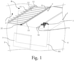
- an automated device 1 object of the present invention progresses on a building panel 2 which covers a ceiling 3 located in a room shown schematically on the figure 1 by two sections of walls 5, 6 inclined at 90° relative to a horizontal plane, this horizontal plane being parallel to a plane of main extension of the ceiling 3.
- One of the sections of walls is pierced with a window 7.
- the other has none.
- This situation is not limiting, and it is envisaged by the invention to arrange the automated device 1 on a construction panel 2 participating in forming or covering one or the other of the sections of walls 5, 6.
- the construction panel 2 is thus secured to the ceiling 3 via a framework 8. More specifically, a plurality of construction panels 2 are secured to this ceiling via this framework 8.
- the fixing of one of these construction panels 2 on this ceiling 3 is in progress, that is to say that the automated device 1 according to the invention is in the process of fixing the construction panel 2 on the framework 8, itself fixed beforehand on the ceiling 3.
- the fixing of the construction panel 2 on the framework 8 is an example of a mechanical operation that the automated device 1 can implement, the description given below being in connection with this operation of fixing the construction panel 2 on the frame 8.
- This framework 8 may for example consist of a metal framework comprising rails 11 mounted on uprights 12 perpendicular to these rails 11.
- the framework 8 may comprise a plurality of rails 11, the rails 11 being supported by a plurality of uprights 12, the uprights 12 extending perpendicularly to the rails 11.
- These rails 11 respectively form a zone for supporting and fixing the building panel 2.
- each building panel 2 comprises a first edge 15 intended to be fixed on a first rail and a second edge 16 intended to be fixed on a second rail. Provision could also be made for each construction panel 2 to be additionally fixed to two additional central rails, that is to say a third rail and a fourth rail, both for example parallel to this first rail and/or to this second rail.
- the automated device 1 according to the invention is thus configured to fix each construction panel 2 on each of these rails 11.
- the automated device 1 according to the invention has means which allow it to move on the construction panel. construction 2 and means which allow it to adhere independently to the construction panel 2.
- this frame 8 can be made of wood. It is understood that any other material compatible with the invention can be envisaged for producing this frame 8 without departing from the context of the invention.
- each of these fastening means 9 passes through the building panel 2 to plug into one of the rails 11 of the frame 8 and thus ensure this connection.
- these fixing means 9 can be screws, nails or staples.
- Two rectilinear rows of fixing means 9 are illustrated in the figure 1 .
- two adjacent construction panels 2 are fixed on the same rail.
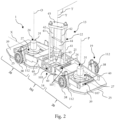
- the automated device 1 comprises only two platforms 20.
- Each platform 20 comprises a plate 39, a suction member 24 and an electric suction motor 31.
- the automated device 1 comprises a frame 14 carrying a tool 13 configured to perform a mechanical operation, the automated device 1 comprising two suction members 24 and four movement means 19.
- Each suction member 24 comprises a chamber 26 allowing the automated device 1 to adhere to a construction panel, the tool 13 being located between the chambers 26. It is understood here that the tool 13 is arranged in a zone provided between the platforms 20. This configuration with the tool 13 positioned between chambers 26 makes it possible to stabilize automated device 1 on the construction panel against which automated device 1 bears, even when carrying out the mechanical operation on the construction panel by the tool.
- the automated device 1 extends along a longitudinal axis X and along a transverse axis X', these axes being mutually perpendicular.
- the frame 14 of the automated device 1 extends along a plane, called the general extension plane of the frame and which corresponds to the longitudinal extension plane of the automated device 1, the general extension plane being that in which the 'longitudinal axis X and transverse axis X'.
- the frame 14 of the automated device 1 corresponds to the supporting structure of the automated device 1.
- the frame 14 comprises reinforcements 21.
- the reinforcements 21 have recesses 105 made for example opposite a central part 101 of the frame 14. According to the example illustrated here, these recesses 105 each have a triangular shape, but it is understood that any other shape could be envisaged without departing from the context of the invention.
- the frame 14 includes additional reinforcements 40.
- the additional reinforcements 40 connect two reinforcements 21 together.
- the additional reinforcements 40 extend perpendicular to the axis along which the reinforcements 21 that they connect extend.
- the additional reinforcements 40 participate in the stiffening of the frame 14 of the automated device 1.
- a pair of additional reinforcements 40 is arranged opposite each platform 20. More specifically, the additional reinforcements 40 are distributed two to two around each suction member 24.
- the additional reinforcements 40 include at least one removal of material 107 so that these additional reinforcements 40 do not weigh down the automated device 1.
- each removal of material 107 takes the form of a slot which extends along the axis of the additional reinforcement 40 in which said removal of material 107 is provided.
- the frame 14 comprises a central part 101, said central part 101 being located between the platforms 20.
- the central part 101 is supported by the reinforcements 21 of the frame 14.
- the frame 14 carries the tool 13.
- the tool 13 of the automated device 1 extends along an axis Y which extends perpendicular to the plane defined by the longitudinal axis X and the transverse axis X'.
- the tool 13 extends towards the top of the automated device 1.
- the central part 101 of the frame 14 comprises an opening 103, the opening 103 allowing the tool 13 to access the construction panel in order to carry out the mechanical operation on said construction panel.
- the platforms 20 are arranged around the tool 13 of the automated device 1.
- Each platform 20 comprises a plate 39, a sealing device 25, a chamber 26, a means 27 and an electric suction motor 31.
- Each plate is fixed to the reinforcements 21 of the frame 14.
- Each chamber 26 is delimited at least partially by a platform 20 distinct from another platform 20.
- Each chamber 26 is located at the level of a lower face of the plate 39, the lower face of the plate 39 being the face of this plate oriented against the construction panel when the device automated 1 adheres to it.
- each chamber 26 has a generally octagonal shape.
- each chamber 26 may have a general shape in the form of a circle, triangle, rectangle or any other geometric shape.
- Each suction member 24 comprises a passage 28 formed through each of the plates 39, said passage 28 allowing each electric suction motor 31 to generate a depression at the level of a corresponding chamber 26.
- Each chamber 26 extends around a central axis O, P, the central axis O, P of a chamber 26 being defined by a straight line which extends perpendicularly to the general extension plane of the automated chassis, said straight passing through the center of chamber 26.
- Each platform 20 supports means 19 for setting the automated device 1 in motion, the two platforms 20 being located symmetrically with respect to one another on either side of the tool 13.
- Each of the two platforms 20 comprises two moving means 19.
- Each moving means 19 comprises a wheel 38 and an electric drive motor, not shown, configured to drive the wheel 38 with which it cooperates.
- Each wheel 38 bears against the construction panel when using the automated device 1.
- Each wheel 38 is supported by a support 112, said support being integral with the plate 39 of a platform 20.
- this fixing tool 13 extends mainly along the direction Y of extension perpendicular to the plane in which the plates 39 of the frame 14 extend.
- the fixing tool 13 comprises at least one head 43 driven by a motor 44, for example an electric motor.
- this head 43 and the motor 44 are carried by a bracket 22 formed of two columns 41 interconnected by a rear block 45. More in particular, the head 43 and the motor 44 are connected to the rear block 45 of the stem 22 by two columns 42 which extend parallel to the Y direction of extension of the fixing tool 13.
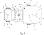
- a first platform 20A comprises a first plate 39A and a second platform 20B comprises a second plate 39B, the first plate 39A having a surface projected onto a lower plane than the surface of the second plate 39B, projected onto the same plane.
- the first platform 20A partially delimits a first chamber 26A.
- the second platform 20B partially delimits a second chamber 26B.
- the first chamber 26A and the second chamber 26B are each delimited by a sealing device 25 as well as by the first plate 39A or the second plate 39B.
- the second chamber 26B has a volume greater than a volume of the first chamber 26A.
- Each chamber 26 is delimited on its outline by the sealing device 25, the sealing device 25 being secured to the plate 39 of the platform 20 supporting said chamber 26.
- the sealing device 25 is a joint which bears against the construction panel when using the automated device 1, said sealing device 25 being positioned on an inner face of the plate 39 of each platform 20.
- the embodiment illustrated in figure 3 And 4 thus makes it possible to compensate for the positioning deviation of the tool 13 with respect to a central transverse plane T of the automated device 1, the central transverse plane T of the automated device 1 being perpendicular to the general extension plane of the frame and located equal distance from the central axis O of the first chamber 26A and from the axis P of the second chamber 26B.
- the offset of the tool 13 causes a shift in the force it generates when performing the mechanical operation.
- the difference in projected surfaces between the first chamber 26A and the second chamber 26B has the function of managing this shift in force, by providing a greater force at the level of the chamber to which the tool is closest.
- the second chamber 26B has a projected surface greater than the projected surface of the first chamber 26A.
- the projected area of the second chamber 26B includes a length greater than the length of the projected area of the first chamber 26A, the length being the dimension parallel to the longitudinal axis X.
- the projected area of the second chamber 26B also includes a width greater than the width of the projected surface of the first chamber 26A, the width being the dimension parallel to the transverse axis X'.
- the passage 28 of the second chamber 26B is offset with respect to the central axis P of the second chamber 26B.
- the passage 28 is thus offset on the axis X towards the tool 13 with respect to the central axis P of the second chamber 26B.
- the movement means 19 supported by the second platform 20B are also offset with respect to the central axis P of the second chamber 26B, such an offset being operated towards the tool 13 with respect to the axis P of the second room 26B.
- an automated device 1 in accordance with the invention comprising four platforms 20.
- the frame 14 comprises the four platforms 20, said platforms 20 being arranged in the plane defined by the longitudinal axis X and by the transverse axis X' of the frame 14.
- the four platforms 20 are regularly angularly arranged around the point of intersection of the Y axis of the tool 13 with the plane defined above, each platform 20 thus being angularly spaced by 90°.
- Each chamber 26 is delimited on its outline by a sealing device 25, the sealing device 25 being secured to the plate 39 of the platform 20 supporting said chamber 26.
- the sealing device 25 is a joint which bears against the panel of construction when using the automated device 1, said sealing device 25 being positioned on an inner face of the plate 39 of each platform 20.
- Two platforms 20 support means 19 for setting the automated device 1 in motion, the two platforms 20 being located symmetrically with respect to one another on either side of the tool 13.
- Each of the two platforms 20 comprises two moving means 19.
- Each moving means 19 comprises a wheel 38 and an electric drive motor, not shown, configured to drive the wheel 38 with which it cooperates.
- Each wheel 38 bears against the construction panel when using the automated device 1.
- Each wheel 38 is supported by a support 112, said support being integral with the plate 39 of a platform 20.
- the other two platforms 20 are devoid of means 19 for setting in motion the automated device 1.
- the tool 13 is positioned between the four platforms 20. This configuration allows the automated device 1 to be stable on the construction panel 2 even when performing a mechanical operation by the tool 13 on the construction panel 2 .
- the invention relates to an automated device 1 configured to move supported on a construction panel 2.
- the automated device 1 comprises a frame 14 carrying a tool 13, said tool 13 being configured to perform a mechanical operation on the construction panel 2.
- the automated device 1 comprises at least one suction device 24 and at least one means 19 for setting the automated device 1 in motion.
- the suction device 24 comprises at least two chambers 26 allowing the device automated 1 to adhere to the construction panel 2, the tool 13 being located between the chambers 26, whether these are two or four in number.
- the different characteristics, forms, variants and embodiments of the invention can be associated with each other according to various combinations insofar as they are not incompatible or exclusive of each other.
- all the variants and embodiments described previously can be combined with each other.
Landscapes
- Engineering & Computer Science (AREA)
- Architecture (AREA)
- Civil Engineering (AREA)
- Structural Engineering (AREA)
- Chemical & Material Sciences (AREA)
- Combustion & Propulsion (AREA)
- Transportation (AREA)
- Mechanical Engineering (AREA)
- Conveying And Assembling Of Building Elements In Situ (AREA)
Description
- Le domaine de la présente invention est celui des dispositifs automatisés utilisés dans la construction de bâtiments, et plus particulièrement des robots capables de réaliser des opérations mécaniques sur des supports employés dans le bâtiment tels que des panneaux de construction.
- Les panneaux de construction sont largement employés dans l'industrie du bâtiment par exemple pour réaliser des cloisons, des sols ou des plafonds, pour habiller de telles surfaces, les isoler thermiquement et/ou acoustiquement, protéger ces surfaces de l'humidité, ou encore doubler ces surfaces. Les panneaux de constructions correspondent à des plaques faites d'un matériau choisi en fonction de son emploi. A titre indicatif, on peut citer les panneaux de constructions comprenant du plâtre, du bois ou des particules de bois, des matériaux synthétiques, des fibres mélangées, des particules minérales, ou un mélange de ces matériaux, ces panneaux de construction pouvant en outre être recouverts d'un revêtement de surface en une matière distincte du matériau choisi.
- Une ossature sert de support à la fixation sur les murs et les plafonds de tels panneaux de construction. Cette intervention nécessite de réaliser plusieurs fixations successives de moyens de fixation. Ces fixations assurent que chaque panneau de construction est solidaire de l'ossature. Pour une fixation optimale, douze vis par mètre carré de panneau de construction sont en moyenne nécessaires. Ainsi, on comprend que pour la réalisation d'une cloison entière, cette étape de fixation des panneaux de construction est particulièrement chronophage pour le technicien en charge de cette opération. Ceci représente un premier inconvénient de la technique connue à ce jour.
- Par ailleurs, les outils de fixation habituellement utilisés sont souvent lourds, ce qui ajoute une contrainte supplémentaire pour le technicien. L'étape de fixation peut alors devenir particulièrement pénible, notamment lorsqu'il s'agit de fixer un panneau de construction sur un plafond ou lorsqu'il s'agit de fixer une partie supérieure du panneau de construction située au-dessus du technicien en charge de l'opération. Ceci représente un second inconvénient.
- Le document
US9221506 - La présente invention a pour but de proposer un dispositif automatisé qui corrige les inconvénients énoncés précédemment et de conduire en outre à d'autres avantages.
- L'invention y parvient grâce à un dispositif automatisé selon la revendication 1 et configuré pour se déplacer en appui sur un panneau de construction, le dispositif automatisé comprenant un châssis porteur d'un outil, ledit outil étant configuré pour réaliser au moins une opération mécanique sur le panneau de construction, le dispositif automatisé comprenant au moins un organe d'aspiration et au moins un moyen de mise en mouvement du dispositif automatisé le long du panneau de construction, le dispositif automatisé comprenant au moins deux chambres configurés pour maintenir le dispositif automatisé contre le panneau de construction, l'outil étant situé entre lesdites au moins deux chambres.
- La présente invention vise donc à répondre aux contraintes énoncées ci-dessus en proposant un dispositif automatisé fiable et capable de se déplacer facilement sur le panneau de construction, réalisant les opérations mécaniques habituellement dévolues au technicien plaquiste. Un tel dispositif automatisé selon l'invention permet d'effectuer en toute sécurité ces opérations mécaniques de manière répétitives sur un panneau de construction couvrant un mur, un plafond ou un plancher. Un tel dispositif automatisé est adapté aux contraintes d'adhérence et de frottement inhérentes à toute inclinaison de la surface sur laquelle il se déplace.
- Cette configuration selon l'invention permet de positionner l'outil entre les chambres du dispositif automatisé, et donc de supprimer tout décalage de l'outil par rapport aux chambres. Ainsi, l'outil ne provoque plus de déséquilibre au niveau du dispositif automatisé, favorisant ainsi l'adhérence du dispositif automatisé sur le panneau de construction sur lequel il repose, même lorsque l'outil génère un effort important pendant qu'il met en oeuvre l'opération mécanique.
- L'outil est disposé entre au moins deux chambres en étant placé à l'intérieur d'un unique périmètre joignant un bord extérieur de chaque chambre, un tel bord étant par exemple matérialisé par un dispositif d'étanchéité. Dit autrement, l'outil est entre les chambres et à l'intérieur d'un polygone passant par un bord externe du châssis.
- A titre indicatif, on peut citer les panneaux de constructions comprenant du plâtre, du bois ou des particules de bois, des matériaux synthétiques, des fibres mélangées, des particules minérales, ou un mélange de ces matériaux, ces panneaux de construction pouvant en outre être recouverts d'un revêtement de surface en une matière distincte du matériau choisi.
- Selon un aspect de l'invention, le dispositif automatisé comprend au moins un moteur électrique d'aspiration et l'au moins un organe d'aspiration comprend des moyens de mise en dépression, lesdits moyens de mise en dépression générant une dépression au niveau desdites au moins deux chambres lorsqu'ils sont mis en rotation par ledit moteur électrique d'aspiration. La dépression induite par le moteur électrique d'aspiration et les moyens de mise en dépression génère une force d'aspiration au niveau des chambres du dispositif automatisé. Préférentiellement, les moyens de mise en dépression comprennent au moins une hélice, le moteur électrique d'aspiration permettant la mise en rotation de ladite au moins une hélice. La rotation de l'hélice génère alors une dépression au niveau d'au moins une chambre.
- La force d'aspiration générée par l'organe d'aspiration du dispositif automatisé est perpendiculaire à un plan d'extension général du châssis du dispositif automatisé, le châssis du dispositif automatisé étant l'élément constitutif de la structure dudit dispositif automatisé. Plus particulièrement, le plan d'extension général du châssis du dispositif automatisé est le plan le plus grand selon lequel s'étend le châssis du dispositif automatisé. Cette configuration permet de plaquer le dispositif automatisé contre le panneau de construction, quelle que soit l'inclinaison du panneau de construction.
- Selon un aspect de l'invention, le moteur électrique d'aspiration est alimenté par une alimentation électrique externe au dispositif automatisé. Alternativement, le moteur électrique d'aspiration est alimenté par une alimentation électrique intégrée au dispositif automatisé.
- Selon un autre aspect de l'invention, chaque organe d'aspiration comprend au moins un dispositif d'étanchéité et un plateau constitutif du châssis, le dispositif d'étanchéité et le plateau délimitant l'une des chambres.
- Le châssis comprend au moins deux plateformes, chaque plateforme comprenant au moins un plateau, et un organe d'aspiration. Chaque plateau s'étend dans un plan parallèle au plan d'extension général du châssis du dispositif automatisé. Plus particulièrement, chaque plateau comprend une face supérieure et une face inférieure. La face inférieure d'un plateau est orientée vers le panneau de construction lorsque le dispositif automatisé est en appui contre celui-ci. La face supérieure du plateau est la face qui est tournée vers l'outil. Le dispositif d'étanchéité est localisé entre la face inférieure du plateau et le panneau de construction. Ainsi, chaque chambre définit un volume, ledit volume étant délimité par la face inférieure du plateau, par le dispositif d'étanchéité et par une bouche du dispositif d'étanchéité destinée à prendre appui contre le panneau de construction.
- Selon un aspect de l'invention, chaque plateforme du dispositif automatisé supporte un organe d'aspiration. L'organe d'aspiration d'une plateforme est alors associé à la chambre qui délimitée par cette même plateforme.
- Selon au moins une chambre est également délimitée par un dispositif d'étanchéité, ledit dispositif d'étanchéité étant solidaire de la plateforme qui délimite la chambre. Plus particulièrement, une première face du dispositif d'étanchéité est en appui contre la plateforme du dispositif automatisé et une deuxième face du dispositif d'étanchéité est en appui contre le panneau de construction. Cette configuration permet de limiter, voire de supprimer les fuites d'air entre la chambre et l'environnement extérieur, nécessitant ainsi une force d'aspiration plus faible pour faire adhérer le dispositif automatisé au panneau de construction. L'utilisation d'une force d'aspiration plus faible permet une diminution de la quantité d'énergie requise par l'organe d'aspiration pour faire adhérer le dispositif automatisé au panneau de construction. Cette disposition spécifique du dispositif d'étanchéité et de la plateforme garantit également une mise en appui de la plateforme contre le panneau de construction, ce qui contribue significativement à stabiliser le dispositif automatisé quand l'outil est mis en oeuvre.
- Selon un autre aspect de l'invention, la plateforme comprend un orifice permettant une communication entre la chambre et un environnement extérieur à ladite chambre. Cette configuration permet de limiter voire de supprimer la dépression au sein de la chambre.
- La plateforme comporte également un élément d'obturation configuré pour obturer, partiellement ou intégralement, l'orifice de la plateforme. Plus particulièrement, l'élément d'obturation est un clapet, une valve ou un volet. Cette configuration permet une dépression maximale au sein de la chambre lorsque l'orifice de la plateforme est obturé intégralement par l'élément d'obturation. A l'inverse, la dépression au niveau de la chambre est plus faible lorsque l'élément d'obturation n'obture pas intégralement l'orifice de la plateforme. Ainsi, l'élément d'obturation de l'orifice de la plateforme permet une modulation du niveau de dépression au sein de la chambre comprenant un tel élément d'obturation.
- La force d'aspiration nécessaire pour faire adhérer le dispositif automatisé au panneau de construction peut varier, notamment en fonction de l'angle d'inclinaison du panneau de construction par rapport à un plan horizontal, ou encore si le dispositif automatisé est suspendu à un plafond, ou encore en fonction d'une contre-force exercée par l'outil sur le panneau de construction, ladite contre-force étant exercée lorsque l'outil réalise une opération mécanique sur le panneau de construction. Ainsi, la force d'aspiration générée par le moteur électrique d'aspiration et les moyens de mise en dépression peut nécessiter d'être modulée. Plus particulièrement, la modulation de la force d'aspiration au niveau d'une chambre peut être obtenue, par exemple, par une modulation de la vitesse de rotation de l'hélice, ou par la modulation de l'ouverture de l'élément d'obturation de la plateforme.
- Selon un premier mode de réalisation, l'organe d'aspiration du dispositif automatisé comprend un unique moteur électrique d'aspiration configuré pour générer une force d'aspiration au niveau desdites au moins deux chambres. Plus particulièrement, l'organe d'aspiration comprend un unique moyen de mise en dépression coopérant avec lesdites au moins deux chambres. Alternativement, l'organe d'aspiration comprend un unique moteur électrique d'aspiration et au moins deux moyens de mise en dépression, lesdits au moins deux moyens de mise en dépression coopérant chacun avec une chambre distincte.
- Selon un deuxième mode de réalisation, l'organe d'aspiration du dispositif automatisé comprend au moins deux moteurs électriques configurés pour générer une force d'aspiration au niveau desdites au moins deux chambres, chaque moteur électrique d'aspiration coopérant avec une chambre distincte d'une autre chambre. Plus particulièrement, chaque moteur électrique d'aspiration coopère avec un moyen de mise en dépression distinct afin de générer une force d'aspiration au niveau d'une chambre distincte de l'autre chambre. En d'autres termes, chaque moteur électrique d'aspiration est associé à une unique chambre.
- Selon un autre aspect de l'invention, lesdites au moins deux chambres sont régulièrement angulairement disposées autour de l'outil.
- Cette configuration permet de stabiliser le dispositif automatisé sur le panneau de construction. Ainsi, si le dispositif automatisé comprend deux chambres, lesdites deux chambres sont angulairement espacées de 180° l'une par rapport à l'autre. D'autre part, dans le cas où le dispositif automatisé comprend trois chambres, lesdites trois chambres sont angulairement espacées de 120° l'une par rapport à l'autre. En outre, dans le cas où le dispositif comprend quatre chambres, lesdites quatre chambres sont angulairement espacées de 90° l'une par rapport à l'autre.
- Selon une première alternative de réalisation de l'invention, chaque chambre s'étend autour d'un axe central, l'outil étant disposé à égale distance de l'axe central de chaque chambre. L'axe central d'une chambre est défini par une droite qui s'étend perpendiculairement au plan d'extension général du châssis du dispositif automatisé, ladite droite passant par le centre de la chambre. L'outil est alors situé au niveau d'un plan transversal central du dispositif automatisé, le plan transversal central du dispositif automatisé étant perpendiculaire au plan d'extension général du châssis et situé à égale distance de l'axe central de chaque chambre.
- Selon un aspect de cette première alternative de l'invention, l'organe d'aspiration est configuré pour exercer une force d'aspiration identique, ou sensiblement identique, au niveau de chaque chambre, lesdites chambres étant disposées symétriquement par rapport à l'outil. Deux forces d'aspiration seront considérées comme identique si leur différence d'aspiration n'excède pas 10% de la force de l'une des forces d'aspiration.
- Selon une deuxième alternative de réalisation de l'invention, chaque chambre s'étend autour d'un axe central, l'outil étant plus proche de l'axe central d'une première chambre que de l'axe central de la deuxième chambre. Ainsi, l'outil n'est pas localisé au niveau du plan transversal central du dispositif automatisé. L'outil est décalé par rapport à un plan transversal central, le plan transversal central étant transversal par rapport au plan d'extension longitudinal du dispositif automatisé. Cette configuration permet par exemple de décaler l'outil par rapport au plan transversal central du dispositif automatisé, libérant ainsi un espace qui peut être utilisé pour loger un moteur électrique d'aspiration, ou tout autre périphérique nécessaire au fonctionnement du dispositif automatisé, comme par exemple l'unité de contrôle ou une réserve de dispositif de fixation, comme des vis posées sur un ruban.
- Plus particulièrement selon la deuxième alternative de réalisation, l'organe d'aspiration est configuré pour exercer une force d'aspiration qui compense un décalage de l'outil par rapport au plan transversal central du dispositif automatisé. Ainsi, une force d'aspiration plus importante doit être générée au niveau d'une chambre d'aspiration lors d'un décalage de l'outil vers ladite chambre d'aspiration par rapport au plan transversal central du dispositif automatisé.
- La compensation de ce décalage peut être obtenue de plusieurs façons. Par exemple, la vitesse de rotation des moyens de mise en dépression coopérant avec une chambre peut être modulée afin de fournir une force d'aspiration plus ou moins importante au niveau de la chambre, ladite force d'aspiration étant plus élevée lorsque la vitesse de rotation desdits moyens de mise en dépression augmente. La compensation de l'écart de positionnement de l'outil peut aussi être obtenue par la modulation de l'ouverture de l'orifice de la chambre via l'élément d'obturation, l'obturation de l'orifice de la chambre générant une force d'aspiration plus importante. Enfin, il est possible d'utiliser des chambres ayant des surfaces différentes, la surface d'une chambre correspondant à la projection de la chambre sur la plateforme supportant la chambre.
- Selon un aspect de l'invention, chaque plateforme comprend un passage, ledit passage permettant au dispositif de mise en dépression de générer une dépression au niveau de la chambre. Le passage permet une communication entre le dispositif de mise en dépression et la chambre. Avantageusement, le passage est positionné au niveau de l'axe central de la chambre.
- Selon un autre aspect de l'invention, lesdites au moins deux chambres et l'outil sont alignés selon un même axe. Plus particulièrement, les deux chambres et l'outil sont agencés de manière rectiligne les uns par rapport aux autres.
- Selon un autre aspect de l'invention, l'organe d'aspiration est configuré pour exercer une force, ladite force étant supérieure à la force exercée par le poids du dispositif automatisé. Cette configuration permet au dispositif automatisé d'être plaqué contre le panneau de construction. Plus particulièrement, la somme des forces d'aspiration exercées au niveau desdites au moins deux chambres est supérieure à la somme de la force exercée par le poids du dispositif automatisé et de la force exercée par l'outil sur le panneau de construction. Lorsque l'outil réalise une opération mécanique sur le panneau de construction, l'outil exerce une force sur le panneau de construction, ladite force induisant à son tour une contre-force de valeur identique et de direction opposée. Ainsi, la contre-force exercée par l'outil sur le panneau de construction s'ajoute à la force exercée par le poids du dispositif automatisé. Cette configuration permet au dispositif automatisé d'être plaqué contre le panneau de construction même lorsque l'outil réalise une opération mécanique sur le panneau de construction.
- Selon un aspect de l'invention, au moins une plateforme supporte l'au moins un moyen de mise en mouvement du dispositif automatisé. Les moyens de mise en mouvement du dispositif automatisé sont en appui contre le panneau de construction lorsque le dispositif automatisé adhère audit panneau de construction. Cette configuration permet au dispositif automatisé de se déplacer sur le panneau de construction. Préférentiellement, l'au moins un moyen de mise en mouvement comprend au moins une roue et un moteur électrique d'entraînement de la roue.
- Préférentiellement, les moyens de mise en mouvement du dispositif automatisé sont supportés par au moins deux plateformes distinctes. Cette configuration permet d'accorder une plus grande stabilité au dispositif automatisé sur le panneau de construction.
- Selon un autre aspect de l'invention, l'opération mécanique réalisée par l'outil correspond à une opération de fixation, de découpe ou de ponçage du panneau de construction. Plus particulièrement, la fixation du panneau de construction sur l'ossature peut se faire à l'aide de vis, d'agrafes ou de clous, l'outil étant alors un outil de fixation, notamment une visseuse, une agrafeuse ou une cloueuse, respectivement. D'autre part, la découpe du panneau de construction peut se faire à l'aide d'une scie cloche, d'une scie sauteuse ou encore d'une lame, l'outil étant alors respectivement une scie cloche, une scie sauteuse, ou une lame. Enfin, le ponçage du panneau de construction peut se faire à l'aide de feuilles abrasives, l'outil étant configuré pour provoquer un mouvement de translation ou de rotation des feuilles abrasives contre le panneau de construction, l'outil étant alors une ponceuse.
- Des modes de réalisation variés de l'invention sont prévus, intégrant selon l'ensemble de leurs combinaisons possibles les différentes caractéristiques optionnelles exposées ci-dessus.
- D'autres caractéristiques, détails et avantages de l'invention apparaitront encore au travers de la description qui suit d'une part, et de plusieurs exemples de réalisation donnés à titre indicatif et non limitatif en référence aux dessins schématiques annexés d'autre part, sur lesquels :
- la
FIGURE 1 représente une vue en perspective d'un exemple de réalisation d'un dispositif automatisé conforme à l'invention, ledit dispositif automatisé étant en situation d'utilisation. - la
FIGURE 2 représente une vue en perspective d'un exemple de réalisation d'un dispositif automatisé conforme à l'invention, ledit dispositif comprenant deux plateformes. - la
FIGURE 3 représente une vue en perspective d'un exemple de réalisation d'un dispositif automatisé conforme à l'invention, ledit dispositif comprenant deux chambres de tailles différentes. - la
FIGURE 4 représente une vue du dessous de l'exemple de réalisation illustré à laFIGURE 3 . - la
FIGURE 5 représente une vue en perspective d'un exemple de réalisation d'un dispositif automatisé conforme à l'invention, ledit dispositif comprenant quatre plateformes. - la
FIGURE 6 représente une vue du dessous de l'exemple de réalisation illustré à laFIGURE 5 . - Dans la suite de la description, le dessous du dispositif automatisé correspond à une face du dispositif automatisé du côté des chambres. A l'inverse, le dessus du dispositif automatisé correspond à une face du dispositif automatisé opposée au-dessous du dispositif automatisé.
- En se référant tout d'abord à la
figure 1 , on voit un dispositif automatisé 1 objet de la présente invention en situation. Ce dernier progresse sur un panneau de construction 2 qui recouvre un plafond 3 situé dans une pièce schématisée sur lafigure 1 par deux pans de murs 5, 6 inclinés à 90° par rapport à un plan horizontal, ce plan horizontal étant parallèle à un plan d'extension principal du plafond 3. Un des pans de murs est percé d'une fenêtre 7. L'autre en est dépourvu. Cette mise en situation est non limitative, et il envisagé par l'invention de disposer le dispositif automatisé 1 sur un panneau de construction 2 participant à former ou recouvrant l'un ou l'autre des pans de murs 5, 6. - Le panneau de construction 2 est ainsi solidarisé sur le plafond 3 par l'intermédiaire d'une ossature 8. Plus précisément, une pluralité de panneaux de construction 2 sont solidarisés sur ce plafond par l'intermédiaire de cette ossature 8.
- Selon l'exemple illustré sur la
figure 1 , la fixation de l'un de ces panneaux de construction 2 sur ce plafond 3 est en cours de réalisation, c'est-à-dire que le dispositif automatisé 1 selon l'invention est entrain de fixer le panneau de construction 2 sur l'ossature 8, elle-même fixée préalablement sur le plafond 3. La fixation du panneau de construction 2 sur l'ossature 8 est un exemple d'opération mécanique que le dispositif automatisé 1 peut mettre en oeuvre, la description faite par la suite étant en rapport avec cette opération de fixation du panneau de construction 2 sur l'ossature 8. - Cette ossature 8 peut par exemple consister en une ossature métallique comprenant des rails 11 montés sur des montants 12 perpendiculaires à ces rails 11. Par exemple, l'ossature 8 peut comprendre une pluralité de rails 11, les rails 11 étant supportés par une pluralité de montants 12, les montants 12 s'étendant perpendiculairement aux rails 11. Ces rails 11 forment respectivement une zone d'appui et de fixation du panneau de construction 2. Autrement dit, chaque panneau de construction 2 comprend un premier bord 15 destiné à être fixé sur un premier rail et un deuxième bord 16 destiné à être fixé sur un deuxième rail. On pourra également prévoir que chaque panneau de construction 2 soit en outre fixé sur deux rails supplémentaires centraux, c'est-à-dire un troisième rail et un quatrième rail, tous deux par exemple parallèle à ce premier rail et/ou à ce deuxième rail.
- Le dispositif automatisé 1 selon l'invention est ainsi configuré pour fixer chaque panneau de construction 2 sur chacun de ces rails 11. Pour ce faire, le dispositif automatisé 1 selon l'invention présente des moyens qui lui permettent de se déplacer sur le panneau de construction 2 et des moyens qui lui permettent d'adhérer de manière autonome au panneau de construction 2.
- Alternativement, cette ossature 8 peut être réalisée en bois. Il est entendu que tout autre matériau compatible avec l'invention est envisageable pour réaliser cette ossature 8 sans sortir du contexte de l'invention.
- Tel que représenté, le panneau de construction 2 est solidarisé sur l'ossature 8 grâce à des moyens de fixation 9. On comprend que chacun de ces moyens de fixation 9 traverse le panneau de construction 2 pour se ficher dans l'un des rails 11 de l'ossature 8 et ainsi assurer cette solidarisation. Par exemple, ces moyens de fixation 9 peuvent être des vis, des clous ou encore des agrafes. Deux rangées rectilignes de moyens de fixation 9 sont illustrées dans la
figure 1 . Avantageusement, deux panneaux de construction 2 adjacents sont fixés sur un même rail. Alternativement, on pourra prévoir que chaque panneau de construction 2 soit fixé sur des rails qui lui sont propres. - Tel que représenté sur la
figure 2 , le dispositif automatisé 1 comprend uniquement deux plateformes 20. Chaque plateforme 20 comprend un plateau 39, un organe d'aspiration 24 et un moteur électrique d'aspiration 31. - Le dispositif automatisé 1 comprend un châssis 14 porteur d'un outil 13 configuré pour réaliser une opération mécanique, le dispositif automatisé 1 comprenant deux organes d'aspiration 24 et quatre moyens de mise en mouvement 19. Chaque organe d'aspiration 24 comprend une chambre 26 permettant au dispositif automatisé 1 d'adhérer à un panneau de construction, l'outil 13 étant situé entre les chambres 26. On comprend ici que l'outil 13 est disposé dans une zone ménagée entre les plateformes 20. Cette configuration avec l'outil 13 positionné entre les chambres 26 permet de stabiliser le dispositif automatisé 1 sur le panneau de construction contre lequel le dispositif automatisé 1 est en appui, même lors de la réalisation de l'opération mécanique sur le panneau de construction par l'outil.
- Le dispositif automatisé 1 s'étend selon un axe longitudinal X et selon un axe transversal X', ces axes étant perpendiculaires entre eux.
- Le châssis 14 du dispositif automatisé 1 s'étend selon un plan, dit plan d'extension général du châssis et qui correspond au plan d'extension longitudinal du dispositif automatisé 1, le plan d'extension général étant celui dans lequel s'inscrivent l'axe longitudinal X et l'axe transversal X'.
- Le châssis 14 du dispositif automatisé 1 correspond à la structure porteuse du dispositif automatisé 1. Ainsi, le châssis 14 comprend des renforts 21. Les renfort 21 présentent des évidements 105 ménagés par exemple en regard d'une partie centrale 101 du châssis 14. Selon l'exemple illustré ici, ces évidements 105 ont chacun une forme triangulaire, mais il est entendu que toute autre forme serait envisageable sans sortir du contexte de l'invention.
- Le châssis 14 comprend des renforts additionnels 40. Les renforts additionnels 40 relient deux renforts 21 entre eux. Les renforts additionnels 40 s'étendent perpendiculairement à l'axe selon lequel s'étendent les renforts 21 qu'ils relient. Ainsi, les renforts additionnels 40 participent à la rigidification du châssis 14 du dispositif automatisé 1. Selon l'exemple illustré, une paire de renforts additionnels 40 est agencée en regard de chaque plateforme 20. Plus précisément, les renforts additionnels 40 sont répartis deux à deux autour de chaque organe d'aspiration 24.
- Les renforts additionnels 40 comprennent au moins un enlèvement de matière 107 de sorte que ces renforts additionnels 40 n'alourdissent pas le dispositif automatisé 1. Selon l'exemple illustré, chaque enlèvement de matière 107 prend la forme d'une fente qui s'étend selon l'axe du renfort additionnel 40 dans lequel ledit enlèvement de matière 107 est ménagé.
- Le châssis 14 comprend une partie centrale 101, ladite partie centrale 101 étant située entre les plateformes 20. La partie centrale 101 est supportée par les renforts 21 du châssis 14.
- Le châssis 14 est porteur de l'outil 13. L'outil 13 du dispositif automatisé 1 s'étend selon un axe Y qui s'étend perpendiculairement au plan défini par l'axe longitudinal X et l'axe transversal X'. L'outil 13 s'étend vers le dessus du dispositif automatisé 1.
- La partie centrale 101 du châssis 14 comprend une ouverture 103, l'ouverture 103 permettant à l'outil 13 d'accéder au panneau de construction afin de réaliser l'opération mécanique sur ledit panneau de construction.
- Les plateformes 20 sont disposées autour de l'outil 13 du dispositif automatisé 1.
- Chaque plateforme 20 comprend un plateau 39, un dispositif d'étanchéité 25, une chambre 26, un moyen 27 et un moteur électrique d'aspiration 31. Chaque plateau est fixé sur les renforts 21 du châssis 14. Chaque chambre 26 est délimitée au moins partiellement par une plateforme 20 distincte d'une autre plateforme 20. Chaque chambre 26 est située au niveau d'une face inférieure du plateau 39, la face inférieure du plateau 39 étant la face de ce plateau orientée contre le panneau de construction lorsque le dispositif automatisé 1 adhère sur celui-ci. Dans l'exemple de réalisation illustré aux
figures 2 et3 , chaque chambre 26 possède une forme générale octogonale. Alternativement, chaque chambre 26 peut posséder une forme générale en forme de cercle, de triangle, de rectangle ou toute autre forme géométrique. - Chaque organe d'aspiration 24 comprend un passage 28 ménagé au travers de chacun des plateaux 39, ledit passage 28 permettant à chaque moteur électrique d'aspiration 31 de générer une dépression au niveau d'une chambre 26 correspondante.
- Chaque chambre 26 s'étend autour d'un axe central O, P, l'axe central O, P d'une chambre 26 étant défini par une droite qui s'étend perpendiculairement au plan d'extension général du châssis automatisé, ladite droite passant par le centre de la chambre 26.
- Chaque plateforme 20 supporte des moyens de mise en mouvement 19 du dispositif automatisé 1, les deux plateformes 20 étant situées symétriquement l'une par rapport à l'autre de part et d'autre de l'outil 13. Chacune des deux plateformes 20 comprend deux moyens de mise en mouvement 19. Chaque moyen de mise en mouvement 19 comprend une roue 38 et un moteur électrique d'entrainement, non représenté, configuré pour entraîner la roue 38 avec laquelle il coopère. Chaque roue 38 vient en appui contre le panneau de construction lors d'une utilisation du dispositif automatisé 1. Chaque roue 38 est supportée par un support 112, ledit support étant solidaire du plateau 39 d'une plateforme 20.
- Dans sa généralité, cet outil de fixation 13 s'étend principalement selon la direction Y d'extension perpendiculaire au plan dans lequel s'étendent les plateaux 39 du châssis 14. L'outil de fixation 13 comprend au moins une tête 43 pilotée par un moteur 44, par exemple un moteur électrique. Tel que représenté sur la
figure 2 , cette tête 43 et le moteur 44 sont portés par une potence 22 formée de deux colonnes 41 reliées entre elles par un bloc arrière 45. Plus particulièrement, la tête 43 et le moteur 44 sont reliés au bloc arrière 45 de la potence 22 par deux colonnettes 42 qui s'étendent parallèlement à la direction Y d'extension de l'outil de fixation 13. - Cette configuration dans laquelle l'outil 13 est positionné entre les plateformes 20, et donc entre les chambres 26 délimitées partiellement par les plateformes 20, permet d'assurer la stabilité du dispositif automatisé 1 sur le panneau de construction, même lors de la réalisation d'une opération mécanique par l'outil 13 sur le panneau de construction.
- En référence aux
figures 3 et4 , un exemple de réalisation d'un dispositif automatisé 1 conforme à l'invention est décrit, ledit dispositif automatisé 1 comprenant deux plateformes 20A, 20B de tailles différentes. Ainsi, une première plateforme 20A comprend un premier plateau 39A et une deuxième plateforme 20B comprend un deuxième plateau 39B, le premier plateau 39A ayant une surface projetée sur un plan plus faible que la surface du deuxième plateau 39B, projetée sur un même plan. - La première plateforme 20A délimite partiellement une première chambre 26A. La deuxième plateforme 20B délimite partiellement une deuxième chambre 26B. La première chambre 26A et la deuxième chambre 26B sont chacune délimitées par un dispositif d'étanchéité 25 ainsi que par le premier plateau 39A ou le deuxième plateau 39B. La deuxième chambre 26B est d'un volume supérieur à un volume de la première chambre 26A.
- Chaque chambre 26 est délimitée sur son contour par le dispositif d'étanchéité 25, le dispositif d'étanchéité 25 étant solidaire du plateau 39 de la plateforme 20 supportant ladite chambre 26. Le dispositif d'étanchéité 25 est un joint qui vient en appui contre le panneau de construction lors d'une utilisation du dispositif automatisé 1, ledit dispositif d'étanchéité 25 étant positionné sur une face intérieure du plateau 39 de chaque plateforme 20.
- L'exemple de réalisation illustré aux
figures 3 et4 permet ainsi de compenser l'écart de positionnement de l'outil 13 par rapport à un plan transversal central T du dispositif automatisé 1, le plan transversal central T du dispositif automatisé 1 étant perpendiculaire au plan d'extension général du châssis et situé à égale distance de l'axe central O de la première chambre 26A et de l'axe P de la deuxième chambre 26B. En effet, le décalage de l'outil 13 provoque un décalage de la force qu'il génère quand il réalise l'opération mécanique. La différence de surfaces projetées entre la première chambre 26A et la deuxième chambre 26B a pour fonction de gérer ce décalage de force, en offrant une force plus importante au niveau de la chambre dont l'outil est le plus proche. - Ainsi, la deuxième chambre 26B présente une surface projetée supérieure à la surface projetée de la première chambre 26A. La surface projetée de la deuxième chambre 26B comprend une longueur supérieure à la longueur de la surface projetée de la première chambre 26A, la longueur étant la dimension parallèle à l'axe longitudinal X. La surface projetée de la deuxième chambre 26B comprend également une largeur supérieure à la largeur de la surface projetée de la première chambre 26A, la largeur étant la dimension parallèle à l'axe transversal X'.
- Le passage 28 de la deuxième chambre 26B est décalé par rapport à l'axe central P de la deuxième chambre 26B. Le passage 28 est ainsi décalé sur l'axe X vers l'outil 13 par rapport à l'axe central P de la deuxième chambre 26B.
- Les moyens de mise en mouvement 19 supportés par la deuxième plateforme 20B sont également décalés par rapport à l'axe central P de la deuxième chambre 26B, un tel décalage étant opéré vers l'outil 13 par rapport à l'axe P de la deuxième chambre 26B.
- En référence aux
figures 5 et6 , un exemple de réalisation d'un dispositif automatisé 1 conforme à l'invention est décrit, ledit dispositif automatisé 1 comprenant quatre plateformes 20. - Le châssis 14 comprend les quatre plateformes 20, lesdites plateformes 20 étant disposées dans le plan défini par l'axe longitudinal X et par l'axe transversal X' du châssis 14. Les quatre plateformes 20 sont régulièrement angulairement disposées autour du point d'intersection de l'axe Y de l'outil 13 avec le plan défini ci-dessus, chaque plateforme 20 étant ainsi angulairement espacée de 90°.
- Chaque chambre 26 est délimitée sur son contour par un dispositif d'étanchéité 25, le dispositif d'étanchéité 25 étant solidaire du plateau 39 de la plateforme 20 supportant ladite chambre 26. Le dispositif d'étanchéité 25 est un joint qui vient en appui contre le panneau de construction lors d'une utilisation du dispositif automatisé 1, ledit dispositif d'étanchéité 25 étant positionné sur une face intérieure du plateau 39 de chaque plateforme 20.
- Deux plateformes 20 supportent des moyens de mise en mouvement 19 du dispositif automatisé 1, les deux plateformes 20 étant situées symétriquement l'une par rapport à l'autre de part et d'autre de l'outil 13. Chacune des deux plateformes 20 comprend deux moyens de mise en mouvement 19. Chaque moyen de mise en mouvement 19 comprend une roue 38 et un moteur électrique d'entrainement, non représenté, configuré pour entraîner la roue 38 avec laquelle il coopère. Chaque roue 38 vient en appui contre le panneau de construction lors d'une utilisation du dispositif automatisé 1. Chaque roue 38 est supportée par un support 112, ledit support étant solidaire du plateau 39 d'une plateforme 20. Les deux autres plateformes 20 sont dépourvus de moyens de mise en mouvement 19 du dispositif automatisé 1.
- L'outil 13 est positionné entre les quatre plateformes 20. Cette configuration permet au dispositif automatisé 1 d'être stable sur le panneau de construction 2 même lors de la réalisation d'une opération mécanique par l'outil 13 sur le panneau de construction 2.
- La description des plateformes 20 effectuée ci-dessus est valable pour chacune des quatre plateformes 20 constitutives de la variante illustrée au
figures 5 et6 . - En synthèse, l'invention concerne un dispositif automatisé 1 configuré pour se déplacer en appui sur un panneau de construction 2. Le dispositif automatisé 1 comprend un châssis 14 porteur d'un outil 13, ledit outil 13 étant configuré pour réaliser une opération mécanique sur le panneau de construction 2. Le dispositif automatisé 1 comprend au moins un organe d'aspiration 24 et au moins un moyen de mise en mouvement 19 du dispositif automatisé 1. L'organe d'aspiration 24 comprend au moins deux chambres 26 permettant au dispositif automatisé 1 d'adhérer au panneau de construction 2, l'outil 13 étant situé entre les chambres 26, que celles-ci soient au nombre de deux ou de quatre.
- Bien sûr, l'invention n'est pas limitée aux exemples qui viennent d'être décrits et de nombreux aménagements peuvent être apportés à ces exemples sans sortir du cadre de l'invention, qui est définie par les revendications ci-jointes.
- Notamment, les différentes caractéristiques, formes, variantes et modes de réalisation de l'invention peuvent être associées les unes avec les autres selon diverses combinaisons dans la mesure où elles ne sont pas incompatibles ou exclusives les unes des autres. En particulier, toutes les variantes et modes de réalisation décrits précédemment sont combinables entre eux.
Claims (10)
- Dispositif automatisé (1) configuré pour se déplacer en appui sur un panneau de construction (2), le dispositif automatisé comprenant un châssis (14) porteur d'un outil (13), ledit outil (13) étant configuré pour réaliser au moins une opération mécanique sur le panneau de construction (2), le dispositif automatisé (1) comprenant au moins un organe d'aspiration (24) et au moins un moyen de mise en mouvement (19) du dispositif automatisé (1) le long du panneau de construction (2), l'organe d'aspiration (24) comprenant au moins deux chambres (26) configurées pour maintenir le dispositif automatisé (1) contre le panneau de construction (2), l'organe d'aspiration (24) comprenant au moins un dispositif d'étanchéité (25) et un plateau (39, 39A, 39B) constitutif du châssis (14), le dispositif d'étanchéité (25) et le plateau (39, 39A, 39B) délimitant l'une des chambres (26, 26A, 26B,
le dispositif étant caractérisé en ce que l'outil (13) est situé entre lesdites au moins deux chambres (26, 26A, 26B). - Dispositif automatisé (1) selon la revendication précédente, comprenant au moins un moteur électrique d'aspiration (31) relié aux chambres (26, 26A, 26B) de sorte à générer dans ces chambres (26) une dépression.
- Dispositif automatisé (1) selon l'une quelconque des revendications précédentes, dans lequel lesdites au moins deux chambres (26, 26A, 26B) sont régulièrement angulairement disposées autour de l'outil (13).
- Dispositif automatisé (1) selon l'une quelconque des revendications précédentes, dans lequel chaque chambre (26A, 26B) s'étend autour d'un axe central (O, P), l'outil (13) étant disposé à égale distance de l'axe central (O, P) de chaque chambre (26A, 26B).
- Dispositif automatisé (1) selon l'une quelconque des revendications 1 à 3, dans lequel chaque chambre (26A, 26B) s'étend autour d'un axe central (O, P), l'outil (13) étant plus proche de l'axe central (O) d'une première chambre (26A) que de l'axe central (P) de la deuxième chambre (26B).
- Dispositif automatisé (1) selon la revendication 5, dans lequel l'organe d'aspiration (24) est configuré pour exercer une force d'aspiration qui compense un décalage de l'outil (13) par rapport à un plan transversal central (T) du dispositif automatisé (1).
- Dispositif automatisé (1) selon l'une quelconque des revendications précédentes, dans lequel une surface projetée sur un plan de l'une chambre (26B) est supérieure à une surface projetée sur ce même plan de l'autre chambre (26A).
- Dispositif automatisé (1) selon l'une quelconque des revendications précédentes, dans lequel au moins deux chambres (26) et l'outil (13) sont alignés sur un même axe (X).
- Dispositif automatisé (1) selon l'une quelconque des revendications précédentes dans lequel l'organe d'aspiration (24) est configuré pour que la somme des forces d'aspiration exercées au niveau au moins des deux chambres (26) est supérieure à la somme d'une force exercée par le poids du dispositif automatisé (1) et d'une force exercée par l'outil (13) sur le panneau de construction (2).
- Dispositif automatisé (1) selon l'une quelconque des revendications précédentes, dans lequel l'outil (13) est choisi parmi une visseuse, une agrafeuse, un pistolet à clous, une scie cloche, une scie sauteuse, une lame ou une ponceuse.
Applications Claiming Priority (2)
| Application Number | Priority Date | Filing Date | Title |
|---|---|---|---|
| FR1852937A FR3079861B1 (fr) | 2018-04-04 | 2018-04-04 | Dispositif automatise pour panneaux de construction |
| PCT/FR2019/050782 WO2019193285A1 (fr) | 2018-04-04 | 2019-04-03 | Dispositif automatise pour panneaux de construction |
Publications (2)
| Publication Number | Publication Date |
|---|---|
| EP3774506A1 EP3774506A1 (fr) | 2021-02-17 |
| EP3774506B1 true EP3774506B1 (fr) | 2023-08-02 |
Family
ID=62816740
Family Applications (1)
| Application Number | Title | Priority Date | Filing Date |
|---|---|---|---|
| EP19721660.9A Active EP3774506B1 (fr) | 2018-04-04 | 2019-04-03 | Dispositif automatisé pour panneaux de construction |
Country Status (7)
| Country | Link |
|---|---|
| US (1) | US11981378B2 (fr) |
| EP (1) | EP3774506B1 (fr) |
| CN (1) | CN112236357B (fr) |
| CA (1) | CA3095923A1 (fr) |
| ES (1) | ES2960812T3 (fr) |
| FR (1) | FR3079861B1 (fr) |
| WO (1) | WO2019193285A1 (fr) |
Families Citing this family (1)
| Publication number | Priority date | Publication date | Assignee | Title |
|---|---|---|---|---|
| CN113719089B (zh) * | 2021-09-29 | 2022-10-28 | 嘉兴市天坤营造工程设计有限公司 | 一种建筑施工用墙砖贴附方法及装置 |
Citations (1)
| Publication number | Priority date | Publication date | Assignee | Title |
|---|---|---|---|---|
| US20150003927A1 (en) * | 2013-06-28 | 2015-01-01 | The Boeing Company | Magnet sensing hole driller and method therefor |
Family Cites Families (19)
| Publication number | Priority date | Publication date | Assignee | Title |
|---|---|---|---|---|
| FR2625459B1 (fr) * | 1987-12-31 | 1990-06-15 | Aerospatiale | Mobile autonome du type robot pour le transport d'un outil a vitesse constante |
| JPH0316887A (ja) * | 1989-06-14 | 1991-01-24 | M Eng:Kk | 壁面吸着走行装置 |
| JP2896389B2 (ja) * | 1991-09-27 | 1999-05-31 | 東芝プラント建設株式会社 | 壁面又は窓ガラスの清掃装置の真空吸盤 |
| JP3137460B2 (ja) * | 1992-10-16 | 2001-02-19 | 三菱重工業株式会社 | 吸着式移動マニピュレータ |
| SE506056C2 (sv) * | 1996-02-16 | 1997-11-03 | Novator Ab | Utrustning för upptagning av en hål- eller urtagsformation i ett krökt eller plant väggelement samt för utskärning av ett till hål- eller urtagsformationen, passande skivformigt materialstycke |
| JP3364586B2 (ja) * | 1998-01-17 | 2003-01-08 | 株式会社交永 | 走行装置 |
| JP2000302071A (ja) * | 1999-04-19 | 2000-10-31 | Jiyakusutoron Kk | 作業用自走車 |
| WO2003022532A2 (fr) * | 2001-09-09 | 2003-03-20 | Advanced Robotic Vehicles, Inc. | Robot portant un outil adherant aux surfaces |
| ES2325433B1 (es) * | 2006-07-31 | 2010-06-21 | Airbus Operations, S.L. | Robot trepador equipado con una unidad de trabajo, y equipo de gobierno de tales robots trepadores. |
| FR2934966B1 (fr) * | 2008-08-12 | 2010-09-17 | Airbus France | Systeme de percage et procede |
| US8413307B2 (en) * | 2009-07-06 | 2013-04-09 | The Boeing Company | Guide assembly and method |
| US8738226B2 (en) * | 2011-07-18 | 2014-05-27 | The Boeing Company | Holonomic motion vehicle for travel on non-level surfaces |
| US9221506B1 (en) * | 2011-07-18 | 2015-12-29 | The Boeing Company | Location tracking and motion control of automated marking device |
| US9636753B2 (en) * | 2012-02-13 | 2017-05-02 | The Commonwealth Of Australia | Alignment device for drilling or reaming an opening in a structure |
| US10001245B2 (en) * | 2014-12-08 | 2018-06-19 | The Boeing Company | Apparatus and method for coupling an end effector to a structure |
| CN205554361U (zh) * | 2016-05-06 | 2016-09-07 | 吉林大学 | 一种模块化飞行爬壁机器人 |
| WO2018135229A1 (fr) * | 2017-01-18 | 2018-07-26 | パナソニックIpマネジメント株式会社 | Dispositif de déplacement par aspiration sur surface murale |
| US11007635B2 (en) * | 2018-07-25 | 2021-05-18 | The Boeing Company | Gravity compensation for self-propelled robotic vehicles crawling on non-level surfaces |
| US11502729B1 (en) * | 2021-08-10 | 2022-11-15 | The Boeing Company | Methods for through-structure power and data transfer between mobile robots and sensor nodes |
-
2018
- 2018-04-04 FR FR1852937A patent/FR3079861B1/fr active Active
-
2019
- 2019-04-03 WO PCT/FR2019/050782 patent/WO2019193285A1/fr not_active Ceased
- 2019-04-03 CA CA3095923A patent/CA3095923A1/fr active Pending
- 2019-04-03 EP EP19721660.9A patent/EP3774506B1/fr active Active
- 2019-04-03 CN CN201980037410.4A patent/CN112236357B/zh active Active
- 2019-04-03 ES ES19721660T patent/ES2960812T3/es active Active
- 2019-04-03 US US17/044,915 patent/US11981378B2/en active Active
Patent Citations (1)
| Publication number | Priority date | Publication date | Assignee | Title |
|---|---|---|---|---|
| US20150003927A1 (en) * | 2013-06-28 | 2015-01-01 | The Boeing Company | Magnet sensing hole driller and method therefor |
Also Published As
| Publication number | Publication date |
|---|---|
| ES2960812T3 (es) | 2024-03-06 |
| EP3774506A1 (fr) | 2021-02-17 |
| US20210039730A1 (en) | 2021-02-11 |
| WO2019193285A1 (fr) | 2019-10-10 |
| CA3095923A1 (fr) | 2019-10-10 |
| CN112236357B (zh) | 2023-03-21 |
| US11981378B2 (en) | 2024-05-14 |
| CN112236357A (zh) | 2021-01-15 |
| FR3079861B1 (fr) | 2021-01-01 |
| FR3079861A1 (fr) | 2019-10-11 |
Similar Documents
| Publication | Publication Date | Title |
|---|---|---|
| EP3774505B1 (fr) | Dispositif automatise pour panneaux de construction | |
| WO2005024154A1 (fr) | Plancher | |
| WO1990009505A2 (fr) | Dispositif d'assemblage de cadres et moulures d'encadrement et machine a couper d'onglet pour la mise en ×uvre du dispositif | |
| EP2300113A2 (fr) | Dispositif portatif pour l'affutage des carres d'un ski | |
| EP3774506A1 (fr) | Dispositif automatise pour panneaux de construction | |
| EP2399797A1 (fr) | Élément de liaison élastique destiné au montage flottant d'un plancher interne, panneau de plancher interne équipé d'une pluralité d'éléments de liaison élastique et procédé de montage flottant d'un plancher | |
| EP2907631B1 (fr) | Butée à double fonction pour un outil de découpe de plaque | |
| FR3079540A1 (fr) | Dispositif de coffrage a montage ameliore | |
| EP3783166A1 (fr) | Dispositif d'entretoisement comprenant un kit de fixation d'un systeme de doublage sur une structure a doubler | |
| EP2907630B1 (fr) | Butée amovible pour un outil de coupe de plaque et outil de coupe comportant une telle butée amovible | |
| EP0248684B1 (fr) | Ossature de second oeuvre | |
| WO2023198983A1 (fr) | Caisson d'aspiration apte à être désassemblé pour un préhenseur | |
| EP1281823B1 (fr) | Lame de plancher de type parquet et outil pour assembler de telles lames | |
| EP3933260A1 (fr) | Dispositif d eclairage industriel | |
| FR2642460A1 (fr) | Dispositif de coffrage d'une chape sur une surface horizontale | |
| EP4415927B1 (fr) | Outil de serrage et de maintien pour des lames de terrasse, de plancher ou de bardage | |
| EP3986683A1 (fr) | Dispositif d'ouverture par decoupe de colis, notamment de colis en carton, et kit comprenant ledit dispositif d'ouverture | |
| FR3079860A1 (fr) | Dispositif automatise pour panneaux de construction | |
| WO2020109700A1 (fr) | Outil de vissage comprenant un moyen d'abrasion | |
| EP4127351B1 (fr) | Profile de cadre pour la realisation d'une fausse paroi retroeclairee et une telle fausse paroi retroeclairee | |
| WO2024126928A1 (fr) | Dispositif d'application d'une bande | |
| EP0684349A1 (fr) | Dispositif d'assemblage de deux éléments de construction, pièces d'assemblage et éléments de construction conçus pour la réalisation de ce dispositif d'assemblage | |
| FR2898617A1 (fr) | Element pour cadre-treillis pour la construction d'une surface d'habillage sensiblement plane | |
| FR3077833A1 (fr) | Dispositif de coffrage avec dispositif de serrage permettant un serrage deporte | |
| WO2020109847A1 (fr) | Outil de découpe de lés de matériau en chevauchement |
Legal Events
| Date | Code | Title | Description |
|---|---|---|---|
| STAA | Information on the status of an ep patent application or granted ep patent |
Free format text: STATUS: UNKNOWN |
|
| STAA | Information on the status of an ep patent application or granted ep patent |
Free format text: STATUS: THE INTERNATIONAL PUBLICATION HAS BEEN MADE |
|
| PUAI | Public reference made under article 153(3) epc to a published international application that has entered the european phase |
Free format text: ORIGINAL CODE: 0009012 |
|
| STAA | Information on the status of an ep patent application or granted ep patent |
Free format text: STATUS: REQUEST FOR EXAMINATION WAS MADE |
|
| 17P | Request for examination filed |
Effective date: 20201002 |
|
| AK | Designated contracting states |
Kind code of ref document: A1 Designated state(s): AL AT BE BG CH CY CZ DE DK EE ES FI FR GB GR HR HU IE IS IT LI LT LU LV MC MK MT NL NO PL PT RO RS SE SI SK SM TR |
|
| AX | Request for extension of the european patent |
Extension state: BA ME |
|
| DAV | Request for validation of the european patent (deleted) | ||
| DAX | Request for extension of the european patent (deleted) | ||
| STAA | Information on the status of an ep patent application or granted ep patent |
Free format text: STATUS: EXAMINATION IS IN PROGRESS |
|
| 17Q | First examination report despatched |
Effective date: 20220405 |
|
| GRAP | Despatch of communication of intention to grant a patent |
Free format text: ORIGINAL CODE: EPIDOSNIGR1 |
|
| STAA | Information on the status of an ep patent application or granted ep patent |
Free format text: STATUS: GRANT OF PATENT IS INTENDED |
|
| INTG | Intention to grant announced |
Effective date: 20230222 |
|
| GRAS | Grant fee paid |
Free format text: ORIGINAL CODE: EPIDOSNIGR3 |
|
| GRAA | (expected) grant |
Free format text: ORIGINAL CODE: 0009210 |
|
| STAA | Information on the status of an ep patent application or granted ep patent |
Free format text: STATUS: THE PATENT HAS BEEN GRANTED |
|
| AK | Designated contracting states |
Kind code of ref document: B1 Designated state(s): AL AT BE BG CH CY CZ DE DK EE ES FI FR GB GR HR HU IE IS IT LI LT LU LV MC MK MT NL NO PL PT RO RS SE SI SK SM TR |
|
| REG | Reference to a national code |
Ref country code: GB Ref legal event code: FG4D Free format text: NOT ENGLISH |
|
| REG | Reference to a national code |
Ref country code: CH Ref legal event code: EP |
|
| REG | Reference to a national code |
Ref country code: DE Ref legal event code: R096 Ref document number: 602019034010 Country of ref document: DE |
|
| REG | Reference to a national code |
Ref country code: IE Ref legal event code: FG4D Free format text: LANGUAGE OF EP DOCUMENT: FRENCH |
|
| REG | Reference to a national code |
Ref country code: LT Ref legal event code: MG9D |
|
| REG | Reference to a national code |
Ref country code: NL Ref legal event code: MP Effective date: 20230802 |
|
| REG | Reference to a national code |
Ref country code: AT Ref legal event code: MK05 Ref document number: 1594411 Country of ref document: AT Kind code of ref document: T Effective date: 20230802 |
|
| PG25 | Lapsed in a contracting state [announced via postgrant information from national office to epo] |
Ref country code: GR Free format text: LAPSE BECAUSE OF FAILURE TO SUBMIT A TRANSLATION OF THE DESCRIPTION OR TO PAY THE FEE WITHIN THE PRESCRIBED TIME-LIMIT Effective date: 20231103 |
|
| PG25 | Lapsed in a contracting state [announced via postgrant information from national office to epo] |
Ref country code: IS Free format text: LAPSE BECAUSE OF FAILURE TO SUBMIT A TRANSLATION OF THE DESCRIPTION OR TO PAY THE FEE WITHIN THE PRESCRIBED TIME-LIMIT Effective date: 20231202 |
|
| PG25 | Lapsed in a contracting state [announced via postgrant information from national office to epo] |
Ref country code: SE Free format text: LAPSE BECAUSE OF FAILURE TO SUBMIT A TRANSLATION OF THE DESCRIPTION OR TO PAY THE FEE WITHIN THE PRESCRIBED TIME-LIMIT Effective date: 20230802 Ref country code: RS Free format text: LAPSE BECAUSE OF FAILURE TO SUBMIT A TRANSLATION OF THE DESCRIPTION OR TO PAY THE FEE WITHIN THE PRESCRIBED TIME-LIMIT Effective date: 20230802 Ref country code: PT Free format text: LAPSE BECAUSE OF FAILURE TO SUBMIT A TRANSLATION OF THE DESCRIPTION OR TO PAY THE FEE WITHIN THE PRESCRIBED TIME-LIMIT Effective date: 20231204 Ref country code: NO Free format text: LAPSE BECAUSE OF FAILURE TO SUBMIT A TRANSLATION OF THE DESCRIPTION OR TO PAY THE FEE WITHIN THE PRESCRIBED TIME-LIMIT Effective date: 20231102 Ref country code: NL Free format text: LAPSE BECAUSE OF FAILURE TO SUBMIT A TRANSLATION OF THE DESCRIPTION OR TO PAY THE FEE WITHIN THE PRESCRIBED TIME-LIMIT Effective date: 20230802 Ref country code: LV Free format text: LAPSE BECAUSE OF FAILURE TO SUBMIT A TRANSLATION OF THE DESCRIPTION OR TO PAY THE FEE WITHIN THE PRESCRIBED TIME-LIMIT Effective date: 20230802 Ref country code: LT Free format text: LAPSE BECAUSE OF FAILURE TO SUBMIT A TRANSLATION OF THE DESCRIPTION OR TO PAY THE FEE WITHIN THE PRESCRIBED TIME-LIMIT Effective date: 20230802 Ref country code: IS Free format text: LAPSE BECAUSE OF FAILURE TO SUBMIT A TRANSLATION OF THE DESCRIPTION OR TO PAY THE FEE WITHIN THE PRESCRIBED TIME-LIMIT Effective date: 20231202 Ref country code: HR Free format text: LAPSE BECAUSE OF FAILURE TO SUBMIT A TRANSLATION OF THE DESCRIPTION OR TO PAY THE FEE WITHIN THE PRESCRIBED TIME-LIMIT Effective date: 20230802 Ref country code: GR Free format text: LAPSE BECAUSE OF FAILURE TO SUBMIT A TRANSLATION OF THE DESCRIPTION OR TO PAY THE FEE WITHIN THE PRESCRIBED TIME-LIMIT Effective date: 20231103 Ref country code: FI Free format text: LAPSE BECAUSE OF FAILURE TO SUBMIT A TRANSLATION OF THE DESCRIPTION OR TO PAY THE FEE WITHIN THE PRESCRIBED TIME-LIMIT Effective date: 20230802 Ref country code: AT Free format text: LAPSE BECAUSE OF FAILURE TO SUBMIT A TRANSLATION OF THE DESCRIPTION OR TO PAY THE FEE WITHIN THE PRESCRIBED TIME-LIMIT Effective date: 20230802 |
|
| PG25 | Lapsed in a contracting state [announced via postgrant information from national office to epo] |
Ref country code: PL Free format text: LAPSE BECAUSE OF FAILURE TO SUBMIT A TRANSLATION OF THE DESCRIPTION OR TO PAY THE FEE WITHIN THE PRESCRIBED TIME-LIMIT Effective date: 20230802 |
|
| REG | Reference to a national code |
Ref country code: ES Ref legal event code: FG2A Ref document number: 2960812 Country of ref document: ES Kind code of ref document: T3 Effective date: 20240306 |
|
| PG25 | Lapsed in a contracting state [announced via postgrant information from national office to epo] |
Ref country code: SM Free format text: LAPSE BECAUSE OF FAILURE TO SUBMIT A TRANSLATION OF THE DESCRIPTION OR TO PAY THE FEE WITHIN THE PRESCRIBED TIME-LIMIT Effective date: 20230802 Ref country code: RO Free format text: LAPSE BECAUSE OF FAILURE TO SUBMIT A TRANSLATION OF THE DESCRIPTION OR TO PAY THE FEE WITHIN THE PRESCRIBED TIME-LIMIT Effective date: 20230802 Ref country code: EE Free format text: LAPSE BECAUSE OF FAILURE TO SUBMIT A TRANSLATION OF THE DESCRIPTION OR TO PAY THE FEE WITHIN THE PRESCRIBED TIME-LIMIT Effective date: 20230802 Ref country code: DK Free format text: LAPSE BECAUSE OF FAILURE TO SUBMIT A TRANSLATION OF THE DESCRIPTION OR TO PAY THE FEE WITHIN THE PRESCRIBED TIME-LIMIT Effective date: 20230802 Ref country code: CZ Free format text: LAPSE BECAUSE OF FAILURE TO SUBMIT A TRANSLATION OF THE DESCRIPTION OR TO PAY THE FEE WITHIN THE PRESCRIBED TIME-LIMIT Effective date: 20230802 Ref country code: SK Free format text: LAPSE BECAUSE OF FAILURE TO SUBMIT A TRANSLATION OF THE DESCRIPTION OR TO PAY THE FEE WITHIN THE PRESCRIBED TIME-LIMIT Effective date: 20230802 |
|
| REG | Reference to a national code |
Ref country code: DE Ref legal event code: R097 Ref document number: 602019034010 Country of ref document: DE |
|
| PG25 | Lapsed in a contracting state [announced via postgrant information from national office to epo] |
Ref country code: IT Free format text: LAPSE BECAUSE OF FAILURE TO SUBMIT A TRANSLATION OF THE DESCRIPTION OR TO PAY THE FEE WITHIN THE PRESCRIBED TIME-LIMIT Effective date: 20230802 |
|
| PLBE | No opposition filed within time limit |
Free format text: ORIGINAL CODE: 0009261 |
|
| STAA | Information on the status of an ep patent application or granted ep patent |
Free format text: STATUS: NO OPPOSITION FILED WITHIN TIME LIMIT |
|
| 26N | No opposition filed |
Effective date: 20240503 |
|
| PG25 | Lapsed in a contracting state [announced via postgrant information from national office to epo] |
Ref country code: SI Free format text: LAPSE BECAUSE OF FAILURE TO SUBMIT A TRANSLATION OF THE DESCRIPTION OR TO PAY THE FEE WITHIN THE PRESCRIBED TIME-LIMIT Effective date: 20230802 |
|
| PG25 | Lapsed in a contracting state [announced via postgrant information from national office to epo] |
Ref country code: BG Free format text: LAPSE BECAUSE OF FAILURE TO SUBMIT A TRANSLATION OF THE DESCRIPTION OR TO PAY THE FEE WITHIN THE PRESCRIBED TIME-LIMIT Effective date: 20230802 |
|
| PG25 | Lapsed in a contracting state [announced via postgrant information from national office to epo] |
Ref country code: MC Free format text: LAPSE BECAUSE OF FAILURE TO SUBMIT A TRANSLATION OF THE DESCRIPTION OR TO PAY THE FEE WITHIN THE PRESCRIBED TIME-LIMIT Effective date: 20230802 |
|
| PG25 | Lapsed in a contracting state [announced via postgrant information from national office to epo] |
Ref country code: MC Free format text: LAPSE BECAUSE OF FAILURE TO SUBMIT A TRANSLATION OF THE DESCRIPTION OR TO PAY THE FEE WITHIN THE PRESCRIBED TIME-LIMIT Effective date: 20230802 Ref country code: BG Free format text: LAPSE BECAUSE OF FAILURE TO SUBMIT A TRANSLATION OF THE DESCRIPTION OR TO PAY THE FEE WITHIN THE PRESCRIBED TIME-LIMIT Effective date: 20230802 |
|
| REG | Reference to a national code |
Ref country code: CH Ref legal event code: PL |
|
| PG25 | Lapsed in a contracting state [announced via postgrant information from national office to epo] |
Ref country code: LU Free format text: LAPSE BECAUSE OF NON-PAYMENT OF DUE FEES Effective date: 20240403 |
|
| REG | Reference to a national code |
Ref country code: BE Ref legal event code: MM Effective date: 20240430 |
|
| PG25 | Lapsed in a contracting state [announced via postgrant information from national office to epo] |
Ref country code: LU Free format text: LAPSE BECAUSE OF NON-PAYMENT OF DUE FEES Effective date: 20240403 |
|
| PG25 | Lapsed in a contracting state [announced via postgrant information from national office to epo] |
Ref country code: BE Free format text: LAPSE BECAUSE OF NON-PAYMENT OF DUE FEES Effective date: 20240430 |
|
| PG25 | Lapsed in a contracting state [announced via postgrant information from national office to epo] |
Ref country code: BE Free format text: LAPSE BECAUSE OF NON-PAYMENT OF DUE FEES Effective date: 20240430 Ref country code: CH Free format text: LAPSE BECAUSE OF NON-PAYMENT OF DUE FEES Effective date: 20240430 |
|
| PG25 | Lapsed in a contracting state [announced via postgrant information from national office to epo] |
Ref country code: IE Free format text: LAPSE BECAUSE OF NON-PAYMENT OF DUE FEES Effective date: 20240403 |
|
| PGFP | Annual fee paid to national office [announced via postgrant information from national office to epo] |
Ref country code: DE Payment date: 20250305 Year of fee payment: 7 |
|
| PGFP | Annual fee paid to national office [announced via postgrant information from national office to epo] |
Ref country code: ES Payment date: 20250508 Year of fee payment: 7 |
|
| PG25 | Lapsed in a contracting state [announced via postgrant information from national office to epo] |
Ref country code: CY Free format text: LAPSE BECAUSE OF FAILURE TO SUBMIT A TRANSLATION OF THE DESCRIPTION OR TO PAY THE FEE WITHIN THE PRESCRIBED TIME-LIMIT; INVALID AB INITIO Effective date: 20190403 |
|
| PG25 | Lapsed in a contracting state [announced via postgrant information from national office to epo] |
Ref country code: HU Free format text: LAPSE BECAUSE OF FAILURE TO SUBMIT A TRANSLATION OF THE DESCRIPTION OR TO PAY THE FEE WITHIN THE PRESCRIBED TIME-LIMIT; INVALID AB INITIO Effective date: 20190403 |
|
| PG25 | Lapsed in a contracting state [announced via postgrant information from national office to epo] |
Ref country code: TR Free format text: LAPSE BECAUSE OF FAILURE TO SUBMIT A TRANSLATION OF THE DESCRIPTION OR TO PAY THE FEE WITHIN THE PRESCRIBED TIME-LIMIT Effective date: 20230802 |
|
| PGFP | Annual fee paid to national office [announced via postgrant information from national office to epo] |
Ref country code: GB Payment date: 20260313 Year of fee payment: 8 |
|
| PGFP | Annual fee paid to national office [announced via postgrant information from national office to epo] |
Ref country code: FR Payment date: 20260309 Year of fee payment: 8 |