EP3772641B1 - Éléments piézorésistifs adaptés thermiquement dans des ponts - Google Patents
Éléments piézorésistifs adaptés thermiquement dans des ponts Download PDFInfo
- Publication number
- EP3772641B1 EP3772641B1 EP19215614.9A EP19215614A EP3772641B1 EP 3772641 B1 EP3772641 B1 EP 3772641B1 EP 19215614 A EP19215614 A EP 19215614A EP 3772641 B1 EP3772641 B1 EP 3772641B1
- Authority
- EP
- European Patent Office
- Prior art keywords
- resistance devices
- pressure sensor
- piezoresistive
- disposed
- resistor
- Prior art date
- Legal status (The legal status is an assumption and is not a legal conclusion. Google has not performed a legal analysis and makes no representation as to the accuracy of the status listed.)
- Active
Links
Images

Classifications
-
- G—PHYSICS
- G01—MEASURING; TESTING
- G01L—MEASURING FORCE, STRESS, TORQUE, WORK, MECHANICAL POWER, MECHANICAL EFFICIENCY, OR FLUID PRESSURE
- G01L9/00—Measuring steady of quasi-steady pressure of fluid or fluent solid material by electric or magnetic pressure-sensitive elements; Transmitting or indicating the displacement of mechanical pressure-sensitive elements, used to measure the steady or quasi-steady pressure of a fluid or fluent solid material, by electric or magnetic means
- G01L9/02—Measuring steady of quasi-steady pressure of fluid or fluent solid material by electric or magnetic pressure-sensitive elements; Transmitting or indicating the displacement of mechanical pressure-sensitive elements, used to measure the steady or quasi-steady pressure of a fluid or fluent solid material, by electric or magnetic means by making use of variations in ohmic resistance, e.g. of potentiometers, electric circuits therefor, e.g. bridges, amplifiers or signal conditioning
- G01L9/06—Measuring steady of quasi-steady pressure of fluid or fluent solid material by electric or magnetic pressure-sensitive elements; Transmitting or indicating the displacement of mechanical pressure-sensitive elements, used to measure the steady or quasi-steady pressure of a fluid or fluent solid material, by electric or magnetic means by making use of variations in ohmic resistance, e.g. of potentiometers, electric circuits therefor, e.g. bridges, amplifiers or signal conditioning of piezo-resistive devices
- G01L9/065—Measuring steady of quasi-steady pressure of fluid or fluent solid material by electric or magnetic pressure-sensitive elements; Transmitting or indicating the displacement of mechanical pressure-sensitive elements, used to measure the steady or quasi-steady pressure of a fluid or fluent solid material, by electric or magnetic means by making use of variations in ohmic resistance, e.g. of potentiometers, electric circuits therefor, e.g. bridges, amplifiers or signal conditioning of piezo-resistive devices with temperature compensating means
-
- G—PHYSICS
- G01—MEASURING; TESTING
- G01L—MEASURING FORCE, STRESS, TORQUE, WORK, MECHANICAL POWER, MECHANICAL EFFICIENCY, OR FLUID PRESSURE
- G01L19/00—Details of, or accessories for, apparatus for measuring steady or quasi-steady pressure of a fluent medium insofar as such details or accessories are not special to particular types of pressure gauges
- G01L19/04—Means for compensating for effects of changes of temperature, i.e. other than electric compensation
-
- G—PHYSICS
- G01—MEASURING; TESTING
- G01L—MEASURING FORCE, STRESS, TORQUE, WORK, MECHANICAL POWER, MECHANICAL EFFICIENCY, OR FLUID PRESSURE
- G01L9/00—Measuring steady of quasi-steady pressure of fluid or fluent solid material by electric or magnetic pressure-sensitive elements; Transmitting or indicating the displacement of mechanical pressure-sensitive elements, used to measure the steady or quasi-steady pressure of a fluid or fluent solid material, by electric or magnetic means
- G01L9/0041—Transmitting or indicating the displacement of flexible diaphragms
- G01L9/0051—Transmitting or indicating the displacement of flexible diaphragms using variations in ohmic resistance
- G01L9/0052—Transmitting or indicating the displacement of flexible diaphragms using variations in ohmic resistance of piezoresistive elements
Definitions
- the present application relates to pressure sensors, and more particularly, to aircraft pitot and static pressure sensors having micromechanical piezoresistive elements.
- Probes and associated pressure sensors are utilized to determine characteristics of an environment.
- air data probes e.g., pitot and/or pitot-static probes
- pitot and/or pitot-static probes can be implemented on the external portions of the aircraft to aid in determination of conditions such as true airspeed, calibrated airspeed, Mach number, altitude, angle of attack, angle of sideslip, or other air data parameters.
- a typical configuration can utilize a pitot tube external to an aircraft, connected by a pneumatic tube to a micromechanical piezoresistive sensor element.
- the micromechanical piezoresistive sensor elements can be installed on a pressure diaphragm that is influenced by air pressure communicated via the pneumatic tube.
- JP S61 70765 A describes a semiconductor pressure sensor having diffused resistors connected in a bridge circuit. Dummy diffused resistors are arranged side by side with the diffused resistors for heat generation so that the temperature rise of each diffused resistance is the same.
- a micromechanical pressure sensor is described herein and defined in claim 1.
- a method for using a micromechanical pressure sensor to measure a pressure differential across a diaphragm is also described herein and defined in claim 11.
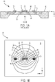
- FIG. 1A is a side view of a piezoresistive pressure sensor of the prior art. Shown in FIG. 1 are piezoresistive pressure sensor 10, sensor body 12, diaphragm 14, pressure surface 16, resistor surface 18, first resistor 21, second resistor 22, third resistor 23, and fourth resistor 24. Piezoresistive pressure sensor 10 includes sensor body 12 and can be located within an enclosure (not shown). Diaphragm 14 includes pressure surface 16 and resistor surface 18. A pressure to be sensed, when applied to diaphragm 14, applies a force to pressure surface 16.
- Resistor surface 18 is on the opposite side of diaphragm 14 from pressure surface 16 and includes an arrangement of four piezoresistors, first resistor 21, second resistor 22, third resistor 23, and fourth resistor 24, each of which has a resistance value that varies in response to an induced mechanical strain caused by force acting on diaphragm 14.
- First, second, third, and fourth resistors 21, 22, 23, and 24 are substantially similar in physical shape and size, and can be arranged in a Wheatstone bridge circuit (not shown in FIG. 1A ) to produce an electrical signal that is indicative of the sensed pressure.
- Air data systems that employ piezoresistive pressure sensor 10, including first, second, third, and fourth resistors 21, 22, 23, and 24, are known to those who are skilled in the pressure-sensing art.
- first, second, third, and fourth resistors 21, 22, 23, and 24 conduct electrical current while configured in a Wheatstone bridge circuit for sensing a pressure that is applied to piezoresistive pressure sensor 10.
- Current flowing through first, second, third, and fourth resistors 21, 22, 23, and 24 results in power dissipation in each, resulting in a temperature increase over that of sensor body 12.
- This can be described as a self-heating effect, which drives heat flow Q ⁇ from first, second, third, and fourth resistors 21, 22, 23, and 24 downward (i.e., in the direction of the z-axis as shown in FIG. 1A ) and toward sensor body 12 (i.e., outward, as shown in FIG. 1A ).
- Sensor body 12 is the heat sink for heat flow Q ⁇ from first, second, third, and fourth resistors 21, 22, 23, and 24.
- Current flow through a resistor is driven by the voltage across the resistor, resulting in a power dissipation that can be calculated by equation 1, where Voltage is the voltage across the resistor and Resistance is the electrical resistance value of the resistor.
- Power Voltage 2 Resistance
- FIG. 1B is a graph showing temperature iso-contours superimposed on a top view of piezoresistive pressure sensor 10 shown in FIG. 1A .
- Shown in FIG. 1B are first resistor 21, second resistor 22, third resistor 23, fourth resistor 24, thermal graph 30, first thermal region 31, second thermal region 32, third thermal region 33, fourth thermal region 34, fifth thermal region 35, sixth thermal region 36, seventh thermal region 37, eighth thermal region 38, and ninth thermal region 39.
- First, second, third, and fourth resistors 21, 22, 23, and 24 each have a serpentine shape when viewed from the top.
- the serpentine shape of piezoresistive elements used in piezoresistive pressure sensors is known to those who are skilled in the pressure-sensing art.
- Thermal graph 30 shows a thermal gradient profile across piezoresistive pressure sensor 10 when first, second, third, and fourth resistors 21, 22, 23, and 24 are conducting electrical current resulting in self-heating, as described above in regard to FIG. 1A .
- the self-heating by first, second, third, and fourth resistors 21, 22, 23, and 24 establishes equilibrium temperature conditions as depicted in thermal graph 30, with a resulting non-uniform temperature profile across piezoresistive pressure sensor 10.
- First through ninth thermal regions 31 - 39 indicate a temperature rise (i.e., relative increase) over the bulk temperature of sensor body 12.
- Several factors cause the non-uniform temperature profile including the physical sizes of first, second, third, and fourth resistors 21, 22, 23, and 24, the physical size of sensor body 12, the thermal conductivity of various materials that comprise piezoresistive pressure sensor 10, and so on.
- Table 1 provides the following isothermal regions (i.e., isotherms) that are defined by the temperature boundaries shown in thermal graph 30.
- Table 1 Thermal region Minimum temperature rise (deg. C) Maximum temperature rise (deg. C) first thermal region 31 0 C 0.16 C second thermal region 32 0.16 C 0.33 C third thermal region 33 0.33 C 0.49 C fourth thermal region 34 0.49 C 0.66 C fifth thermal region 35 0.66 C 0.82 C sixth thermal region 36 0.82 C 0.99 C seventh thermal region 37 0.99 C 1.15 C eighth thermal region 38 1.15 C 1.32 C ninth thermal region 39 1.32 C 1.48 C As shown in FIG.
- first and fourth resistors 21, 24 are situated near the edge regions of piezoresistive pressure sensor 10 covered by fourth, fifth, and sixth thermal regions 34, 35, 36 (i.e., bounded by temperatures 0.49 - 0.99 degrees C), whereas second and third resistors 22, 23 are situated near the inner region of piezoresistive pressure sensor 10 covered by eighth and ninth thermal regions 38, 39 (i.e., bounded by temperatures 1.15 - 1.48 degrees C).
- first, second, third, and fourth resistors 21, 22, 23, 24 have a positive temperature coefficient of resistivity.
- first, second, third, and fourth resistors 21, 22, 23, 24 are used in a Wheatstone bridge circuit to provide an indication of the pressure value that is sensed by piezoresistive pressure sensor 10.
- the temperature values shown in table 1 result from an exemplary embodiment in which the resistance values of first resistor 21, second resistor 22, third resistor 23, and fourth resistor 24 are each 10,000 ohms ( ⁇ ).
- FIG. 2 is a graph showing output voltage as a function in excitation voltage for various resistance values for a Wheatstone bridge circuit (not shown in FIG. 2 ) using piezoresistive pressure sensor 10 shown in FIG. 1A . Shown in FIG. 2 are output voltage graph 40, ideal response curve 42, first actual response curve 44, and second actual response curve 46. Ideal response curve 42 shows an idealized response from first, second, third, and fourth resistors 21, 22, 23, 24 in which output voltage (Vout) increases linearly with excitation voltage (V excitation ).
- First actual response curve 44 represents the output behavior in an embodiment where first, second, third, and fourth resistors 21, 22, 23, 24 each have a resistance value of about 10,000 ⁇ (i.e., 10 kQ). As excitation voltage increases from 0 V, output voltage increases but at a decreasing rate (i.e., the slope of first actual response curve 44 is positive but decreasing). Eventually, first actual response curve 44 reaches a maximum value at an excitation voltage of about 20 V. As excitation voltage continues to increase above about 20 V, output voltage decreases at an increasing rate (i.e., the slope of first actual response curve 44 is negative and getting more negative).
- Second actual response curve 46 represents the output behavior in an embodiment where first, second, third, and fourth resistors 21, 22, 23, 24 each have a resistance value of about 700 ⁇ .
- the description of second actual response curve 46 is similar to that provided for first actual response curve 44, second actual response curve 46 reaches a maximum value at an excitation voltage of about 12 V.
- the response of piezoresistive pressure sensor 10 to excitation voltage is a result of the uneven self-heating of first, second, third, and fourth resistors 21, 22, 23, 24, described above in regard to FIG. 1B . Accordingly, smaller resistance values and/or higher values of excitation voltage can be disadvantageous in piezoresistive pressure sensor 10 of the prior art because of an increased self-heating effect, thereby resulting in greater performance non-linearity.
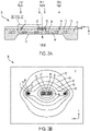
- FIG. 3A is a side view of a micromechanical pressure sensor with thermally-matched piezoresistive elements.
- FIG. 3B is a graph showing temperature iso-contours superimposed on a top view of the micromechanical pressure sensor shown in FIG. 3A .
- FIG. 3C is an enlarged cross-sectional side view of the micromechanical pressure sensor shown in FIG. 3A . Shown in FIGS. 3A and 3C are pressure sensor 50, sensor body 52, diaphragm 54, pressure surface 56, resistor surface 58, first resistor 61, second resistor 62, third resistor 63, fourth resistor 64, isolation layer 70, and overcoat 72. Centerline (CL), inner, and edge regions are labeled in FIGS. 3A and 3C .
- Centerline (CL) inner, and edge regions are labeled in FIGS. 3A and 3C .
- pressure sensor 50 is symmetrical about the centerline.
- First and fourth resistors 61, 64 can be referred to as edge resistors, because they are located near outer edges of diaphragm 54 (i.e., furthest from the centerline).
- First and fourth resistors 61, 64 can also be referred to as periphery resistors.
- Second and third resistors 62, 63 can be referred to as inner resistors, because they are located near the inner region (i.e., nearest the centerline). Second and third resistors 62, 63 can also be referred to as center resistors.
- Edge resistor width W1, inner resistor width W2, and isolation layer thickness T are labeled in FIG. 3C .
- Heat flow Q ⁇ is also depicted in FIG. 3C .
- pressure sensor 50 can be asymmetrical about the center line. In some of these embodiments, pressure sensor 50 can include fewer than four piezoresistive elements. In an exemplary alternative embodiment, pressure sensor 50 can include first resistor 61 (i.e., an edge resistor) and second resistor 62 (i.e., an inner resistor).
- pressure sensor 50 can be located within an enclosure (not shown) that is arranged to subject diaphragm 54 to a pressure source that is to be sensed.
- the pressure source can be a pitot tube (not shown) located external to an aircraft (not shown), with the pressure source being communicated to sensor body 52 by a pneumatic tube (not shown).
- This can be referred to as a dynamic pressure.
- the dynamic pressure is directed to pressure surface 56, applying a force to diaphragm 54, thereby causing diaphragm 54 to deflect in response to the dynamic pressure.
- the force can also be referred to as a load.
- the dynamic pressure is an absolute pressure, whereby pressure communicated by a single pneumatic tube acts on only one surface of diaphragm 54.
- Resistor surface 58 is on the opposite side of diaphragm 54 from pressure surface 56. The deflection of diaphragm 54 induces a mechanical strain in resistor surface 58.
- First resistor 61, second resistor 62, third resistor 63, and fourth resistor 64 are piezoresistive resistors, the resistance (i.e., electrical resistance) of each of which varies in response to the induced mechanical strain.
- Pressure sensor 50 can be also be referred to as a micromechanical pressure sensor, a micromechanical electrical system (MEMS) pressure sensor, a piezoresistive pressure sensor, or a pressure cell.
- MEMS micromechanical electrical system
- first resistor 61, second resistor 62, third resistor 63, and fourth resistor 64 are arranged in a Wheatstone bridge circuit, as will be shown later in FIG. 4 .
- heat flow Q ⁇ from self-heating of first, second, third, and fourth resistors 61, 62, 63, and 64 flows in the z-axis direction across isolation layer 70, then outward to sensor body 52, as shown in FIG. 3A .
- Sensor body 52 is the heat sink for heat flow Q ⁇ from first, second, third, and fourth resistors 61, 62, 63, and 64.
- the pressure to be sensed i.e., a system pressure
- the system pressure is applied to pressure surface 56 of pressure sensor 50, with the system pressure being measured as an absolute pressure (i.e., with respect to a vacuum).
- the system pressure can be applied to resistor surface 58 of pressure sensor 50.
- the pressure to be sensed can be a gage pressure (i.e., relative to atmospheric pressure).
- Pressure sensor 50 can be used in various embodiments to measure a wide range of pressure values, ranging from 0 - 1,000 psi (0 - 6,895 KPa), or higher.
- pressure sensor 50 can be used to sense pressure in a compression stage of a gas turbine engine.
- a differential pressure can be applied between pressure surface 56 and resistor surface 58.
- the high side of the differential pressure to be sensed can be applied to either pressure surface 56 or resistor surface 58.
- pressure sensor 50 can be configured to measure a relatively small differential pressure (e.g., less than about 1 psid (6.9 KPa differential)).
- Isolation layer 70 covers diaphragm 54, thereby providing electrical and thermal isolation of first, second, third, and fourth resistors 61, 62, 63, 64 from diaphragm 54.
- Isolation layer 70 can also be referred to as an insulating layer, or as an insulator.
- isolation layer 70 is made of silicon dioxide (i.e., silicon oxide).
- isolation layer 70 can be silicon nitride, aluminum oxide, polyimide, or combinations of one or more of the aforementioned materials, or any other dielectric material that provides thermal isolation.
- isolation layer thickness T is about 0.5 ⁇ m (microns). In some embodiments, isolation layer thickness T can range from about 0.1 - 1 ⁇ m.
- isolation layer thickness T can be less than 0.1 ⁇ m or greater than 1 ⁇ m.
- Isolation layer thickness T directly affects heat flow Q ⁇ from first, second, third, and fourth resistors 61, 62, 63, 64. Therefore, isolation layer thickness T can be established for a particular material used for isolation layer 70 to help in providing thermal matching. In some embodiments, isolation layer thickness T can range from about 0.1 - 5 ⁇ m.
- Overcoat 72 forms a conformal protective layer over first, second, third, and fourth resistors 61, 62, 63, 64 to provide electrical isolation and/or protection. Overcoat 72 can also be called a conformal coating or a protective coating. In the illustrated embodiment, overcoat 72 can be a combination of silicon oxide and silicon nitride. In some embodiments, overcoat 72 can be parylene, aluminum oxide, polyimide, or combinations of one or more of the aforementioned materials, or any other dielectric material that provides encapsulation. As will be described in greater detail later in FIG.
- first, second, third, and fourth resistors 61, 62, 63, 64 are all about the same, and can range from about 100 - 50,000 ⁇ (ohms).
- first, second, third, and fourth resistors 61, 62, 63, 64 can each have a resistance value of about 10,000 ⁇ (i.e., 10 k ⁇ ).
- first, second, third, and fourth resistors 61, 62, 63, 64 can each have a resistance value of about 700 ⁇ .
- the Wheatstone bridge resistors can be said to have resistance values that are about the same when the resistance of any resistor is within 10% of a specified resistance value (i.e., + 10%, meaning that no resistor has a resistance value that is more than about 20% of any other). This can be referred to as a resistance value tolerance.
- the resistance value tolerance can be smaller (i.e., tighter).
- the resistance value tolerance can be ⁇ 5% or ⁇ 2%.
- FIG. 3B a graph showing temperature gradients superimposed on a top view of the micromechanical pressure sensor shown in FIG. 3A .
- Shown in FIG. 3B are thermal graph 80, first thermal region 81, second thermal region 82, third thermal region 83, fourth thermal region 84, fifth thermal region 85, sixth thermal region 86, seventh thermal region 87, and eighth thermal region 88.
- Thermal graph 80 shows a thermal gradient profile across pressure sensor 50 when first, second, third, and fourth resistors 61, 62, 63, and 64 are conducting electrical current while configured in a Wheatstone bridge circuit for sensing a pressure that is applied to pressure sensor 50.
- first, second, third, and fourth resistors 61, 62, 63, and 64 can be referred to as the Wheatstone bridge resistors, the bridge resistors, the Wheatstone bridge piezoresistive resistors, or the Wheatstone bridge piezoresistance devices.
- Current flowing through the Wheatstone bridge resistors i.e., first, second, third, and fourth resistors 61, 62, 63, and 64 results in power dissipation by each, which can cause a self-heating effect that can result in a temperature increase in the Wheatstone bridge resistors.
- the Wheatstone bridge resistors each have a serpentine shape when viewed from the top, which provides a greater change in resistance value in response to an applied force, thereby improving the sensitivity of pressure sensor 50.
- An advantage to using a serpentine pattern is the compactness of the piezoresistive material in a relatively small surface area, thereby resulting in a much greater change in resistance in response to an induced stress as opposed to a non-serpentine pattern. Accordingly, a serpentine pattern can provide a relatively high sensitivity when relatively small pressures are measured.
- first and fourth resistors 61, 64 i.e., edge resistors
- second and third resistors 62, 63 i.e., inner resistors
- the gap distance between the serpentine traces remains the same, thereby reducing the overall footprint of the serpentine pattern in the edge resistors (i.e., as compared to the inner resistors).
- the resistance values of first, second, third, and fourth resistors 61, 62, 63, 64 are all about the same. Therefore, the electrical power dissipated by each resistor is about the same (i.e., as given by equation 1).
- first, second, third, and fourth resistors 61, 62, 63, 64 have a serpentine pattern in the illustrated embodiment. In other embodiments, first, second, third, and/or fourth resistors 61, 62, 63, and 64 can have patterns (i.e., shapes, designs) that are different from that depicted in FIG.
- pressure sensor 50 can include more than or fewer than four piezoresistive elements.
- pressure sensor 50 can include multiple (i.e., redundant) piezoresistive elements.
- pressure sensor 50 can include two piezoresistive elements that can be connected in a half-bridge. The present disclosure is directed at thermally-matched piezoresistive elements in any electrical bridge configuration.
- table 2 provides the following thermal regions that are defined by the temperature boundaries shown in thermal graph 80. Temperatures are in degrees Celsius (C), and indicate the temperature rise (i.e., relative temperature increase) over the bulk temperature of sensor body 52. Table 2 Thermal region Minimum temperature rise (deg. C) Maximum temperature rise (deg.
- first and fourth resistors 61, 64 i.e., edge resistors
- second and third resistors 62, 63 i.e., inner resistors
- all four Wheatstone bridge resistors have an operating temperature that is about the same (i.e., both in thermal regions that are 1.07 - 1.43 degrees C higher than the temperature of sensor body 52).
- the temperature midpoint of each of first, second, third, and fourth resistors 61, 62, 63, 64 is about 1.25 degree C above that of sensor body 52, and all regions of first, second, third, and fourth resistors 61, 62, 63, 64 are within + 0.18 degree C of each other.
- This can be referred to as the bridge resistors being thermally-matched (i.e., thermal matching of Wheatstone bridge resistors), which can eliminate the measurement inaccuracy that is caused by an uneven temperature rise in the Wheatstone bridge resistors.
- Wheatstone bridge resistors can be said to as being thermally-matched when they have substantially the same temperature as each other throughout a full operating voltage range such that an error of pressure sensor 50 output resulting from self-heating is less than if pressure sensor 50 were not configured to maintain the operating temperatures substantially the same.
- all Wheatstone bridge resistor temperatures can be said to be within + 0.2 degree C of each other (i.e., no resistor has a temperature that is more than 0.4 degree C from that of any other).
- all Wheatstone bridge resistor (i.e., bridge resistor) temperatures can within a different temperature value of each other, with the operating temperature difference being either less than (i.e., tighter than) or greater than (i.e., looser than) + 0.2 degree C.
- first, second, third, and fourth resistors 61, 62, 63, 64 are all about the same, and can range from about 100 - 50,000 ⁇ (ohms).
- first, second, third, and fourth resistors 61, 62, 63, 64 can each have a resistance value of about 10,000 ⁇ (i.e., 10 k ⁇ ).
- first, second, third, and fourth resistors 61, 62, 63, 64 can each have a resistance value that is less than about 2,000 ⁇ (i.e., 2 kQ).
- first, second, third, and fourth resistors 61, 62, 63, 64 can each have a resistance value of about 700 ⁇ .
- An advantage of the present disclosure is to provide thermal matching of the Wheatstone bridge piezoresistance devices across all resistance values. Accordingly, resistance values less than about 2 k ⁇ can be used in pressure sensor 50 of the present disclosure, whereas similar resistance values had disadvantages in piezoresistive pressure sensor 10 of the prior art, as described above in regard to FIG. 2 .
- the following equations can be used to model the electrical and thermal behavior of the Wheatstone bridge resistors (i.e., first, second, third, and fourth resistors 61, 62, 63, 64).
- Power dissipation in a resistor is calculated by equation 1, as noted earlier.
- the temperature rise ( ⁇ T) across a thermal insulator is calculated by equation 2, where Power is the internal power dissipation in an element (i.e., power dissipation, resistive heating), area is the planar area of the heat-producing resistor over the insulator, thickness is the thickness of the insulator, and conductivity is the thermal conductivity of the thermal insulator.
- Thermal power can also be referred to as heat flow Q ⁇ (i.e., the rate of delivering thermal energy).
- Equation 2 can be used to describe heat conduction primarily in one dimension, such as heat flowing across isolation layer 70 from first, second, third, and fourth resistors 61, 62, 63, 64 into diaphragm 54, as shown in FIG. 3A .
- ⁇ T Power area length conductvity
- thermal insulator refers to a material that conducts heat poorly, but it is to be understood that unlike electrical insulators which can be modeled as being perfect electrical insulators, most thermal insulators have an appreciable value of thermal conductivity.
- thermal insulator i.e., temperature gradient
- heat flux Q ⁇ i.e., thermal power Q ⁇ per unit area
- Exemplary thermal insulators that can be used as materials in isolation layer 70 are provided in table 3.
- Table 3 Isolation layer material Thermal conductivity (W/m/K) Silicon 149 Aluminum oxide 27 Silicon nitride 25 Silicone oxide 1.4 Polyimide 0.12
- first, second, third, and fourth resistors 61, 62, 63, 64 ⁇ T resistor
- the thin film insulator is an electrical insulator.
- An electrical insulator i.e., insulator
- ⁇ T resistor temperature rise across thin film insultor + temperature rise across diaphragm substrate
- the temperature rise of an edge resistor ( ⁇ T edge ) is calculated by equation 4.
- ⁇ T edge Power edge resistor area insulator thickness insulator conductvity
- ⁇ T inner Power inner resitor area insulator thickness insulator conductvity + Power diaphragm thickness ⁇ effective diaphragm width effective diaphragm length diaphragm conductvity
- insulator thickness insulator conductivity can be referred to as a thermal resistance value, as given in equation 8.
- Insulator thermal resistance insulator thickness insulator conductivity Larger values of insulator thermal resistance can be desirable in some embodiments, with larger values of insulator thermal resistance being achieved by larger values of insulator thickness and/or smaller values of insulator conductivity (i.e., insulator thermal conductivity).
- silicon dioxide i.e., silicon oxide
- table 3 i.e., a thermal conductivity of about 1.4 W/m/K.
- edge resistor area inner resistor area insulator thickness insulator conductivity insulator thickness insulator conductivity + center resistor area diaphragm thickness ⁇ effective diaphragm width effective diaphragm length diaphragm conductivity
- each of the Wheatstone bridge resistors i.e., first, second, third, and fourth resistors 61, 62, 63, 64
- SQ squares
- edge resistor area inner resistor area squares ⁇ edge resistor width 2 squares ⁇ inner resistor width 2 Accordingly, a ratio of the resistor widths can be provided as in equation 14.
- edge resistor width inner resistor width insulator thickness insulator conductivity insulator thickness insulator conductivity + inner resistor area diaphragm thickness ⁇ effective diaphragm width effective diaphragm length diaphragm conductivity
- edge resistor area inner resistor area can be referred to as the resistor width ratio, and can be expressed as shown in equation 15.
- Resistor width ratio edge resistor width inner resistor width inner resistor width
- the resistor width ratio is about 0.4.
- Several factors can be used to determine the size ratio in a particular embodiment, with exemplary factors being the particular geometries of the Wheatstone bridge resistors (i.e., first, second, third, fourth resistors 61, 62, 63, 64), the material used for the thermal insulator (i.e., isolation layer 70), the thickness of the thermal insulator (i.e., isolation layer thickness T), and the geometry of, and materials used for, diaphragm 54 and/or sensor body 52.
- the resistor width ratio can range from about 0.3 - 0.6. In other embodiments, the resistor width ratio can range from about 0.1 - 0.95. In yet other embodiments, the resistor width ratio can be less than 0.1 or greater than 0.95 (i.e., 0.95 - 0.999).
- FIG. 4 is an electrical schematic diagram of a Wheatstone bridge circuit for the micromechanical pressure sensor shown in FIG. 3A . Shown in FIG. 4 are bridge circuit 90, Wheatstone bridge 91, voltage supply 92, and output voltage 94. First, second, third, and fourth resistors 61, 62, 63, 64 (i.e., R1, R2, R3, and R4, respectively) are electrically arranged in Wheatstone bridge 91. Voltage supply 92 can be referred to as the excitation voltage (V excitation ). Voltage V from voltage supply 92 is applied across Wheatstone bridge 91, thereby producing an output voltage (V out ) 94 as indicated. During operation of pressure sensor 50, output voltage 94 is representative of the pressure being sensed by pressure sensor 50.
- V excitation the excitation voltage
- V out output voltage
- output voltage 94 can be amplified, filtered, and converted to a digital signal by an analog-to-digital converter (ADC) before being transmitted to systems.
- voltage supply 92 can have a value of about 10 volts. In some embodiments, voltage supply 92 can range from about 5 - 25 volts. In other embodiments, voltage supply 92 can range from about 3 - 50 volts. In another exemplary embodiment, voltage supply 92 can range from about 3 - 10 volts. In other embodiments, voltage supply 92 can be less than 3 volts. In some of these embodiments, voltage supply 92 can be as small as 0.1 volt. In yet other embodiments, voltage supply 92 can be greater than 50 volts.
- voltage supply 92 can range from about 0.1 - 100 volts. In some embodiments, voltage supply 92 can range to about 1,000 volts, or greater. All values of voltage for voltage supply 92 are within the scope of the present disclosure. It is to be appreciated, as described above, that the present disclosure is immune to the value of power dissipated by each of the Wheatstone bridge resistors, and therefore, to the value of voltage supplied by voltage supply 92.
- the range of possible values of voltage supply 92 in a particular embodiment can be referred to as the operating range. Accordingly, in an exemplary embodiment, the operating range is about 0.1 - 100 volts.
- pressure sensor 50 is configured so that the operating temperature of the bridge resistors is substantially the same as each other throughout a full operating voltage range such that an error of pressure sensor 50 output resulting from self-heating is less than if pressure sensor 50 were not configured to maintain the operating temperatures substantially the same.
- the error can be defined as the difference between the actual sensor output at a particular operating voltage and an ideal sensor output at that same operating voltage (e.g., ideal response curve 42 as shown in FIG. 2 ).
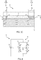
- FIG. 5 is an enlarged cross-sectional side view showing a second embodiment of a micromechanical pressure sensor with thermally-matched piezoresistive elements. It is to be appreciated that the view of FIG. 5 is similar to that shown in FIG. 3C in which only half of the resistors of a Wheatstone bridge circuit are illustrated, with FIG. 5 depicting an enlarged portion of pressure sensor 150 (not shown in its entirety). Shown in FIG. 5 are pressure sensor 150, diaphragm 154, first resistor 161, second resistor 162, edge resistive element 166, isolation layer 170, and overcoat 172. Heat flow Q ⁇ is not depicted in FIG. 5 , for ease of illustration.
- First and second resistors 161, 162 are used in a Wheatstone bridge circuit, as will be shown later in FIG. 6 .
- the descriptions of diaphragm 154, isolation layer 170, and overcoat 172 is substantially similar to that provided above in regard to FIG. 3A .
- First and second resistors 161, 162 are piezoresistive elements, with first resistor 161 being an edge resistor and second resistor 162 being an inner resistor, as described above in regard to FIG. 3A .
- the widths (not labeled) of first and second resistors 161, 162 are about equal to each other, and thermal matching is provided by edge resistive element 166, as will be described herein.
- edge resistive element 166 During operation of pressure sensor 150, electrical current flows through edge resistive element 166, producing heat through power dissipation (i.e., self-heating) that overcomes the greater thermal loss from the edge resistor (i.e., first resistor 161) as compared to the inner resistor (i.e., second resistor 162).
- edge resistive element 166 can be made of doped silicon, doped polysilicon, or various metals, with a non-limiting example being an alloy of nickel and chrome (e.g., NiCr).
- FIG. 6 is an electrical schematic diagram of a Wheatstone bridge circuit and associated circuitry for pressure sensor 150 depicted in FIG. 5 . Shown in FIG. 6 are first, second, third, and fourth resistor 161, 162, 163, 164, edge resistive elements 166A, 166B, bridge circuit 190, Wheatstone bridge 191, voltage supply 192, and output voltage 194. The descriptions of first, second, third, and fourth resistor 161, 162, 163, 164, Wheatstone bridge 191, voltage supply 192, and output voltage 194 is substantially similar to that provided above in regard to FIG. 4 . In the illustrated embodiment, edge resistive elements 166A, 166B receive current flow from voltage supply 192, thereby producing heat (i.e., self-heating), as described above in regard to FIG.
- edge resistive elements 166A, 166B can be selected to provide power dissipation that applies heat to respective first and fourth resistors 161, 164 (i.e., the edge resistors), thereby maintaining the temperature of the edge resistors at the temperature of the inner resistors (i.e., thermal matching).
- Edge resistive elements 166A, 166B can be referred to as edge heaters, or simply, as heaters. Accordingly, edge resistive heaters 166A, 166B are labeled as R H1 and R H2 , respectively.
- first, second, third, and fourth resistor 161, 162, 163, 164 each have a resistance value of about 700 ⁇
- edge resistive elements 166A, 166B each have a resistance value of about 1100 ⁇
- edge resistive elements 166A, 166B i.e., heater resistors
- first, second, third, and fourth resistors 161, 162, 163, 164 can each have a resistance value of can range from about 100 - 50,000 ⁇ (ohms).
- a ratio of heater resistor (R H ) resistance value to bridge resistor (R B ) resistance value can be defined as shown in equation 17.
- Heater resistace ratio R H R B
- the heater resistance ratio is about 1.57 (i.e., 1,100 ⁇ /700 ⁇ ).
- the heater resistance ratio can range from about 1 - 2.6. In other embodiments, the heater resistance ratio can be less than 1 or greater than 2.6.
- exemplary factors can be used in determining the value of heater resistance ratio in a particular embodiment, with exemplary factors being the value of voltage supply 192, particular geometries of the Wheatstone bridge resistors (i.e., first, second, third, fourth resistors 161, 162, 163, 164), the material used for the thermal insulator (i.e., isolation layer 170), the thickness of the thermal insulator (i.e., isolation layer thickness T), and the geometry of and material used for diaphragm 154 and sensor body 152.
- edge resistors e.g., first resistor 161
- inner resistors e.g., second resistor 162
- thermal matching is provided in bridge circuit 190 by the selection of the resistance values of edge resistive elements 166A, 166B, without modifying the widths of the edge resistors relative to the inner resistors as described above in regard to FIGS. 3A - 3C .
- thermal matching can be partially provided in bridge circuit 190 by using edge resistive elements 166A, 166B, and partially by the setting of the resistor width ratio as described above in regard to FIGS. 3A - 3C .
- edge resistive elements 166A, 166B and the resistor width ratio together provide thermal matching in the Wheatstone bridge resistors.
- voltage supply 192 provides current flow through Wheatstone bridge 191 and edge resistive elements 166A, 166B.
- a different voltage source (not shown) can provide current flow to edge resistive elements 166A, 166B.
- the value of the voltage being supplied to edge resistive elements 166A, 166B can be adjusted to provide precise thermal matching in Wheatstone bridge 191 in pressure sensor 150.
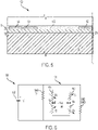
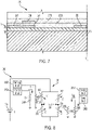
- FIG. 7 is an enlarged cross-sectional side view of a third embodiment of a micromechanical pressure sensor with thermally-matched piezoresistive elements. Shown in FIG. 7 are pressure sensor 250, diaphragm 254, first resistor 261, second resistor 262, edge resistive element 266, vertically-offset resistive element 268, isolation layer 270, first overcoat 272A, and second overcoat 272B. Heat flow Q ⁇ is not depicted in FIG. 5 , for ease of illustration.
- the descriptions of diaphragm 254, first resistor 261, second resistor 262, and isolation layer 270 are substantially as provided above in regard to FIG. 5 .
- the descriptions of first and second overcoat 272A, 272B are substantially as provided above in regard to FIG.
- Edge resistive element 266 is used as a resistive heater, having a description substantially similar to that provided above in regard to FIG. 5 .
- Vertically-offset resistive element 268 is used as a resistance temperature detector (RTD), having an electrical resistance value that varies with temperature. Accordingly, vertically-offset resistive element 268 can be used as a temperature sensor to measure temperature in the vicinity of first resistor 261.
- first, second, third, and fourth resistors 261, 262, 263, 264 and edge resistive elements 266 can be deposited on isolation layer 270, and then first overcoat 272A can be applied.
- vertically-offset resistive elements 268 can be deposited on first overcoat 272A, and then second overcoat 272B can be applied. It is to be appreciated that vertically-offset resistive elements 268 are so-named as a descriptive term with regard to the embodiment shown in FIG. 7 , while not intending to limit the orientation of pressure sensor 50 to a particular orientation when used. Therefore, "vertically-offset" can be interpreted as being offset in a direction that is normal to the surface of diaphragm 270 (e.g., along the z-axis, normal to pressure surface 56 and/or resistor surface 58 as shown in FIG. 3A ).
- FIG. 8 is an electrical schematic diagram of a Wheatstone bridge circuit and associated circuitry for pressure sensor 250 depicted in FIG. 7 . Shown in FIG. 8 are first resistor 261, second resistor 262, third resistor 263, fourth resistor 264, edge resistive elements 266A, 266B, vertically-offset resistive elements 268A, 268B, bridge circuit 290, Wheatstone bridge 291, voltage supply 292, output voltage 294, control circuits 296A, 296B, and sensing circuits 298A, 298B.
- the descriptions of first, second, third, and fourth resistors 261, 262, 263, 264, Wheatstone bridge 291, voltage supply 292, and output voltage 294 are substantially similar to those provided above in regard to FIG. 6 .
- edge resistive element 266A is supplied current I H1 from control circuit 296A
- edge resistive element 266B is supplied current I H2 from control circuit 296B, thereby producing heat (i.e., self-heating) in edge resistive elements 266A, 266B.
- This provides thermal matching of the Wheatstone bridge resistors (i.e., first, second, third, and fourth resistors 261, 262, 263, 264), as described above in regard to FIGS. 6 - 7 .
- edge resistive elements 266A, 266B are labeled as R H1 and R H2 , respectively.
- sensing circuits 298A, 298B each provide a signal (not shown in FIG. 8 ) to respective control circuits 296A, 296B, in turn directing each control circuit 296A, 296B to adjust the value of current flow I H1 , I H2 through the respective edge resistive element 266A, 266B, as necessary to maintain a desired temperature in the vicinity of the respective edge resistor (i.e., first resistor 261, fourth resistor 264, respectively).
- vertically offset resistive elements 268, 268A, 268B can be configured to function as a heater, and edge resistive elements 266, 266A, 266B can be configured to function as a temperature detector (i.e., RTD).
- RTD temperature detector
- the functionality of bridge circuit 290 will be functionally equivalent to that described in regard to FIGS. 7 - 8 , except that the functions of edge resistive elements 266, 266A, 266B and vertically offset resistive elements 268, 268A, 266B will be transposed.
- Edge resistive element 266 and vertically offset resistive element 268 can each be referred to as secondary resistance devices (i.e., resistance devices in pressure sensor 250 that are in addition to the Wheatstone bridge resistors). Therefore, with regard to an edge resistor, one of the secondary resistance devices can be configured to produce heat when supplied by current, and the other secondary resistance device can be configured to sense temperature when connected to a sensing circuit.
- each edge resistor i.e., first resistor 261 and fourth resistor 264 had a separate associated control circuit 296A, 296B and sensing circuit 298A, 298B.
- a single control circuit and/or sensing circuit can be used in bridge circuit 290, controlling currently flows I H1 , I H2 together and/or sensing the temperature in the vicinity of edge resistors together.
- edge resistive element 266 can be omitted from pressure sensor 250 and current can be supplied to vertically-offset resistive element 268, thereby providing power dissipation (i.e., self-heating) to thermally match the inner and edge resistors.
- pressure sensor 250 will be functionally similar to pressure sensor 150 shown and described above in FIGS. 5 - 6 , whereby a single secondary resistance device (i.e., vertically-offset resistive element 268) is associated with each edge resistor (e.g., first resistor 261) to provide self-heating for thermally matching the Wheatstone bridge resistors.
Landscapes
- Physics & Mathematics (AREA)
- General Physics & Mathematics (AREA)
- Measuring Fluid Pressure (AREA)
Claims (15)
- Capteur de pression micromécanique, comprenant :un diaphragme, configuré pour se déformer mécaniquement en réponse à une charge appliquée sur celui-ci, le diaphragme ayant une région interne et deux régions de bord, l'une distale à l'autre par rapport à la région interne ; etdeux dispositifs de résistance piézorésistifs ou plus disposés sur le diaphragme, comprenant :un ou plusieurs dispositifs de résistance piézorésistifs ayant un motif en serpentin disposés dans la région interne ; le motif en serpentin ayant une largeur de ligne ; etun ou plusieurs dispositifs de résistance piézorésistifs ayant un motif en serpentin disposés dans au moins une des régions de bord ; le motif en serpentin ayant une largeur de ligne ;dans lequel :les deux dispositifs de résistance piézorésistifs ou plus sont configurés pour être connectés électriquement dans un circuit en pont ;le capteur de pression micromécanique est configuré de sorte qu'une température de fonctionnement des un ou plusieurs dispositifs de résistance piézorésistifs disposés dans la région interne est sensiblement la même qu'une température de fonctionnement des un ou plusieurs dispositifs de résistance piézorésistifs disposés dans au moins une des régions de bord tout au long d'une plage de fonctionnement complète de sorte qu'une erreur de la sortie de capteur de pression micromécanique résultant de l'auto-chauffage est inférieure à l'éventualité où le capteur de pression micromécanique n'est pas configuré pour maintenir les températures de fonctionnement sensiblement identiques ; un rapport de la largeur de ligne du motif en serpentin de la résistance de bord à la largeur de ligne du motif en serpentin de la résistance interne définit un rapport de largeur de résistance,le rapport de largeur de résistance est inférieur à 0,95, etle rapport de largeur de résistance est configuré de sorte que la température de fonctionnement des un ou plusieurs dispositifs de résistance piézorésistifs disposés dans la région interne est sensiblement la même que la température de fonctionnement des un ou plusieurs dispositifs de résistance piézorésistifs disposés dans au moins une des régions de bord tout au long de la plage de fonctionnement complète de sorte que l'erreur de la sortie de capteur de pression micromécanique résultant de l'auto-chauffage est inférieure à l'éventualité où le capteur de pression micromécanique n'est pas configuré pour maintenir les températures de fonctionnement sensiblement identiques.
- Capteur de pression micromécanique selon la revendication 1, dans lequel :
le rapport de largeur de résistance varie de 0,3 à 0,6. - Capteur de pression micromécanique selon une quelconque revendication précédente, dans lequel :chacun des deux dispositifs de résistance piézorésistifs ou plus définit une valeur de résistance statique ;la valeur de résistance statique de chacun des deux dispositifs de résistance piézorésistifs ou plus est dans les limites de 10 % d'une valeur de résistance particulière ; etla valeur de résistance statique de chacun des deux dispositifs de résistance piézorésistifs ou plus varie de 100 à 50 000 ohms.
- Capteur de pression micromécanique selon une quelconque revendication précédente, dans lequel :le circuit en pont est configuré pour être connecté électriquement à une alimentation en tension ; etl'alimentation en tension varie de 0,1 à 100 volts, etdans lequel l'alimentation en tension varie de 3 à 50 volts.
- Capteur de pression micromécanique selon une quelconque revendication précédente, comprenant en outre une couche d'isolation, dans lequel :la couche d'isolation est disposée sur le diaphragme ; etles deux dispositifs de résistance piézorésistifs ou plus sont disposés sur la couche d'isolation, et éventuellementdans lequel la couche d'isolation a une épaisseur qui varie de 0,1 à 5 µm.
- Capteur de pression micromécanique selon une quelconque revendication précédente, dans lequel les deux dispositifs de résistance piézorésistifs ou plus comprennent :
quatre dispositifs de résistance piézorésistifs disposés sur le diaphragme, comprenant :deux dispositifs de résistance piézorésistifs disposés dans la région interne ; etdeux dispositifs de résistance piézorésistifs disposés dans les régions de bord ; etdans lequel les quatre dispositifs de résistance piézorésistifs sont configurés pour être connectés électriquement dans un circuit en pont de Wheatstone. - Capteur de pression micromécanique selon une quelconque revendication précédente, comprenant en outre un ou plusieurs dispositifs de résistance secondaires, dans lequel :les un ou plusieurs dispositifs de résistance secondaires sont disposés dans au moins une des régions de bord, l'un à proximité de chacun des un ou plusieurs dispositifs de résistance piézorésistifs disposés dans au moins une des régions de bord ; etles un ou plusieurs dispositifs de résistance secondaires sont configurés pour produire de la chaleur lorsque du courant électrique est appliqué sur ceux-ci, de sorte que la température de fonctionnement des un ou plusieurs dispositifs de résistance piézorésistifs disposés dans la région interne est sensiblement la même que la température de fonctionnement des un ou plusieurs dispositifs de résistance piézorésistifs disposés dans la région de bord tout au long de la plage de fonctionnement complète de sorte que l'erreur de la sortie de capteur de pression micromécanique résultant de l'auto-chauffage est inférieure à l'éventualité où le capteur de pression micromécanique n'est pas configuré pour maintenir les températures de fonctionnement sensiblement identiques, et éventuellement dans lequel :chacun des un ou plusieurs dispositifs de résistance secondaires définit une valeur de résistance de dispositif de chauffage ;la valeur de résistance de dispositif de chauffage varie de 100 à 130 000 ohms ;chacun des deux dispositifs de résistance piézorésistifs ou plus définit une valeur de résistance statique ; etun rapport de la valeur de résistance de dispositif de chauffage à la valeur de résistance statique varie de 1 à 2,6.
- Capteur de pression micromécanique selon une quelconque revendication précédente, comprenant en outre deux dispositifs de résistance secondaires ou plus, dans lequel :un premier ou plusieurs des deux dispositifs de résistance secondaires ou plus sont disposés dans au moins une des régions de bord, chacun étant configuré pour produire de la chaleur lorsqu'un courant de chauffage électrique est appliqué sur celui-ci, l'un à proximité de chacun des un ou plusieurs dispositifs de résistance piézorésistifs disposés dans au moins une des régions de bord ; etun second ou plusieurs des deux dispositifs de résistance secondaires ou plus sont disposés dans au moins une des régions de bord, chacun étant configuré pour produire une valeur de résistance représentative d'une température détectée, l'un à proximité de chacun des un ou plusieurs dispositifs de résistance piézorésistifs disposés dans au moins une des régions de bord.
- Capteur de pression micromécanique selon la revendication 8, comprenant en outre :un ou plusieurs circuits de détection, chacun étant configuré pour détecter la valeur de résistance représentative d'une température détectée ; etun ou plusieurs circuits de commande, chacun étant configuré pour produire le courant de chauffage électrique représentatif d'une température souhaitée.
- Capteur de pression micromécanique selon la revendication 9, comprenant en outre un premier revêtement, dans lequel :le premier revêtement recouvre les premier ou plusieurs dispositifs de résistance secondaires disposés dans la région de bord ; etles second ou plusieurs dispositifs de résistance secondaires sont disposés sur le premier revêtement.
- Procédé d'utilisation d'un capteur de pression micromécanique pour mesurer un différentiel de pression à travers un diaphragme configuré pour se déformer mécaniquement en réponse à une charge appliquée sur celui-ci par le différentiel de pression en communication fluidique avec celui-ci, le diaphragme ayant une région interne et deux régions de bord, une région de bord étant distale à l'autre par rapport à la région interne, le capteur de pression micromécanique comprenant deux dispositifs de résistance piézorésistifs ou plus disposés sur le diaphragme, les deux dispositifs de résistance piézorésistifs ou plus comprenant un ou plusieurs dispositifs de résistance piézorésistifs ayant un motif en serpentin disposés dans la région interne, le motif en serpentin ayant une largeur de ligne, et un ou plusieurs dispositifs de résistance piézorésistifs ayant un motif en serpentin disposés dans au moins une des régions de bord, le motif en serpentin étant caractérisé par une largeur de ligne, les deux dispositifs de résistance piézorésistifs ou plus étant configurés pour être connectés électriquement dans un circuit en pont, dans lequel un rapport de la largeur de ligne du motif en serpentin de la résistance de bord à la largeur de ligne du motif en serpentin de la résistance interne définit un rapport de largeur de résistance, et dans lequel le rapport de largeur de résistance est inférieur à 0,95, le procédé comprenant :l'application d'une alimentation en tension au circuit en pont, le circuit en pont étant configuré pour produire une tension de sortie électrique ;la mesure de la tension de sortie électrique ; etla production d'un signal représentatif du différentiel de pression sur la base de la tension de sortie électrique mesurée ;dans lequel le capteur de pression micromécanique est configuré de sorte qu'une température de fonctionnement des un ou plusieurs dispositifs de résistance piézorésistifs disposés dans la région interne est sensiblement la même qu'une température de fonctionnement des un ou plusieurs dispositifs de résistance piézorésistifs disposés dans au moins une des régions de bord tout au long d'une plage de fonctionnement complète de sorte qu'une erreur de la sortie de capteur de pression micromécanique résultant de l'auto-chauffage est inférieure à l'éventualité où le capteur de pression micromécanique n'est pas configuré pour maintenir les températures de fonctionnement sensiblement identiques, dans lequel le rapport de largeur de résistance est configuré de sorte que la température de fonctionnement des un ou plusieurs dispositifs de résistance piézorésistifs disposés dans la région interne est sensiblement la même que la température de fonctionnement des un ou plusieurs dispositifs de résistance piézorésistifs disposés dans au moins une des régions de bord tout au long de la plage de fonctionnement complète de sorte que l'erreur de la sortie de capteur de pression micromécanique résultant de l'auto-chauffage est inférieure à l'éventualité où le capteur de pression micromécanique n'est pas configuré pour maintenir les températures de fonctionnement sensiblement identiques.
- Procédé selon la revendication 11, dans lequel :chacun des un ou plusieurs dispositifs de résistance piézorésistifs disposés dans la région interne et des un ou plusieurs dispositifs de résistance piézorésistifs disposés dans au moins une des régions de bord définit une valeur de résistance statique ;la valeur de résistance statique de chacun des un ou plusieurs dispositifs de résistance piézorésistifs disposés dans la région interne et de chacun des un ou plusieurs dispositifs de résistance piézorésistifs disposés dans au moins une des régions de bord est dans les limites de 10 % d'une valeur de résistance particulière ; etla valeur de résistance statique de chacun des un ou plusieurs dispositifs de résistance piézorésistifs disposés dans la région interne et de chacun des un ou plusieurs dispositifs de résistance piézorésistifs disposés dans au moins une des régions de bord varie de 100 à 50 000 ohms.
- Procédé selon l'une quelconque des revendications 11 et 12, dans lequel :le capteur de pression micromécanique comprend en outre un ou plusieurs dispositifs de résistance secondaires ;les un ou plusieurs dispositifs de résistance secondaires sont disposés dans au moins une des régions de bord, l'un à proximité de chacun des un ou plusieurs dispositifs de résistance piézorésistifs disposés dans au moins une des régions de bord ; etles un ou plusieurs dispositifs de résistance secondaires sont configurés pour produire de la chaleur lorsque du courant électrique est appliqué sur ceux-ci, de sorte que la température de fonctionnement des un ou plusieurs dispositifs de résistance piézorésistifs disposés dans la région interne est sensiblement la même que la température de fonctionnement des un ou plusieurs dispositifs de résistance piézorésistifs disposés dans au moins une des régions de bord tout au long de la plage de fonctionnement complète de sorte que l'erreur de la sortie de capteur de pression micromécanique résultant de l'auto-chauffage est inférieure à l'éventualité où le capteur de pression micromécanique n'est pas configuré pour maintenir les températures de fonctionnement sensiblement identiques.
- Procédé selon l'une quelconque des revendications 11 à 13, dans lequel :chacun des un ou plusieurs dispositifs de résistance secondaires définit une valeur de résistance de dispositif de chauffage ;la valeur de résistance de dispositif de chauffage varie de 100 à 130 000 ohms ;chacun des deux dispositifs de résistance piézorésistifs ou plus définit une valeur de résistance statique ;un rapport de la valeur de résistance de dispositif de chauffage à la valeur de résistance statique varie de 1 à 2,6.
- Procédé selon l'une quelconque des revendications 11 à 14, dans lequel le capteur de pression micromécanique comprend en outre :
deux dispositifs de résistance secondaires ou plus, dans lequel :un premier ou plusieurs des deux dispositifs de résistance secondaires ou plus sont disposés dans au moins une des régions de bord, chacun étant configuré pour produire de la chaleur lorsqu'un courant de chauffage électrique est appliqué sur celui-ci, l'un à proximité de chacun des un ou plusieurs dispositifs de résistance piézorésistifs disposés dans au moins une des régions de bord ; etun second ou plusieurs des deux dispositifs de résistance secondaires ou plus sont disposés dans au moins une des régions de bord, chacun étant configuré pour produire une valeur de résistance représentative d'une température détectée, l'un à proximité de chacun des un ou plusieurs dispositifs de résistance piézorésistifs disposés dans au moins une des régions de bord ;un ou plusieurs circuits de détection, chacun étant configuré pour détecter la valeur de résistance représentative de la température détectée ; etun ou plusieurs circuits de commande, chacun étant configuré pour produire le courant de chauffage électrique représentatif d'une température souhaitée.
Applications Claiming Priority (1)
| Application Number | Priority Date | Filing Date | Title |
|---|---|---|---|
| US16/536,486 US11099093B2 (en) | 2019-08-09 | 2019-08-09 | Thermally-matched piezoresistive elements in bridges |
Publications (2)
| Publication Number | Publication Date |
|---|---|
| EP3772641A1 EP3772641A1 (fr) | 2021-02-10 |
| EP3772641B1 true EP3772641B1 (fr) | 2022-10-26 |
Family
ID=68887319
Family Applications (1)
| Application Number | Title | Priority Date | Filing Date |
|---|---|---|---|
| EP19215614.9A Active EP3772641B1 (fr) | 2019-08-09 | 2019-12-12 | Éléments piézorésistifs adaptés thermiquement dans des ponts |
Country Status (3)
| Country | Link |
|---|---|
| US (1) | US11099093B2 (fr) |
| EP (1) | EP3772641B1 (fr) |
| CA (1) | CA3062688A1 (fr) |
Families Citing this family (5)
| Publication number | Priority date | Publication date | Assignee | Title |
|---|---|---|---|---|
| WO2022056850A1 (fr) * | 2020-09-18 | 2022-03-24 | 深圳纽迪瑞科技开发有限公司 | Capteur de température et de pression et dispositif électronique |
| FR3118830A1 (fr) * | 2021-01-12 | 2022-07-15 | Commissariat A L'energie Atomique Et Aux Energies Alternatives | Dispositif de détection utilisant une transduction piézorésistive |
| CN113063530B (zh) * | 2021-03-30 | 2024-11-08 | 成都凯天电子股份有限公司 | 一种mems硅压阻式压力传感器及其制备方法 |
| CN113301190B (zh) | 2021-04-16 | 2022-08-05 | 荣耀终端有限公司 | 压力传感器和电子设备 |
| US11768121B2 (en) | 2021-11-22 | 2023-09-26 | Rosemount Aerospace Inc. | Pressure sensor with trim resistors |
Citations (1)
| Publication number | Priority date | Publication date | Assignee | Title |
|---|---|---|---|---|
| US4198868A (en) * | 1979-02-12 | 1980-04-22 | Rockwell International Corporation | Strain gauge apparatus and means for treating temperature dependency |
Family Cites Families (14)
| Publication number | Priority date | Publication date | Assignee | Title |
|---|---|---|---|---|
| JPS60128673A (ja) * | 1983-12-16 | 1985-07-09 | Hitachi Ltd | 半導体感圧装置 |
| JPS6170765A (ja) | 1984-09-14 | 1986-04-11 | Fujikura Ltd | 半導体圧力センサ− |
| FR2636737B1 (fr) | 1988-09-16 | 1993-12-03 | Thomson Csf | Capteur de type resistif, de mesure de concentrations relatives d'especes reactives fluides, compense en temperature |
| JPH085570Y2 (ja) | 1990-06-25 | 1996-02-14 | 株式会社東海理化電機製作所 | 圧力センサ |
| JP2000162066A (ja) | 1998-11-26 | 2000-06-16 | Denso Corp | センサ装置 |
| US6860153B2 (en) | 2000-02-22 | 2005-03-01 | Simon Fraser University | Gas pressure sensor based on short-distance heat conduction and method for fabricating same |
| JP2002148131A (ja) | 2000-11-10 | 2002-05-22 | Denso Corp | 物理量検出装置 |
| US7234357B2 (en) * | 2004-10-18 | 2007-06-26 | Silverbrook Research Pty Ltd | Wafer bonded pressure sensor |
| US7856885B1 (en) | 2006-04-19 | 2010-12-28 | University Of South Florida | Reinforced piezoresistive pressure sensor |
| JP5745205B2 (ja) * | 2008-08-22 | 2015-07-08 | 木村 光照 | 加熱励振を利用した熱伝導型気圧センサ |
| US7918137B2 (en) | 2009-02-06 | 2011-04-05 | Kulite Semiconductor Products, Inc. | Method for temperature compensation of a piezoresistive gaged metal diaphragm |
| JP2016095284A (ja) * | 2014-11-17 | 2016-05-26 | セイコーエプソン株式会社 | 電子デバイス、物理量センサー、圧力センサー、高度計、電子機器および移動体 |
| US20160209285A1 (en) * | 2015-01-20 | 2016-07-21 | Seiko Epson Corporation | Pressure sensor, method of manufacturing pressure sensor, altimeter, electronic apparatus, and moving object |
| US11092504B2 (en) * | 2019-05-21 | 2021-08-17 | Rosemount Aerospace Inc. | Micromechanical redundant piezoresistive array pressure sensor |
-
2019
- 2019-08-09 US US16/536,486 patent/US11099093B2/en active Active
- 2019-11-25 CA CA3062688A patent/CA3062688A1/fr active Pending
- 2019-12-12 EP EP19215614.9A patent/EP3772641B1/fr active Active
Patent Citations (1)
| Publication number | Priority date | Publication date | Assignee | Title |
|---|---|---|---|---|
| US4198868A (en) * | 1979-02-12 | 1980-04-22 | Rockwell International Corporation | Strain gauge apparatus and means for treating temperature dependency |
Also Published As
| Publication number | Publication date |
|---|---|
| EP3772641A1 (fr) | 2021-02-10 |
| CA3062688A1 (fr) | 2021-02-09 |
| BR102019026566A2 (pt) | 2021-02-09 |
| US20210041316A1 (en) | 2021-02-11 |
| US11099093B2 (en) | 2021-08-24 |
Similar Documents
| Publication | Publication Date | Title |
|---|---|---|
| EP3772641B1 (fr) | Éléments piézorésistifs adaptés thermiquement dans des ponts | |
| JP4307738B2 (ja) | 圧力センサ | |
| EP2846143B1 (fr) | Capteur de pression | |
| JP4608843B2 (ja) | 流量測定装置 | |
| EP3104137A1 (fr) | Capteur avec stabilité thermique améliorée | |
| JPH0257853B2 (fr) | ||
| US6470742B1 (en) | Flow sensor | |
| JP6603633B2 (ja) | センサ装置 | |
| EP1530028A1 (fr) | Débitmètre à technologies multiples | |
| US20020086460A1 (en) | Pressure transducer employing on-chip resistor compensation | |
| JP2006258676A (ja) | 熱式流量計 | |
| JPH07193194A (ja) | 半導体装置およびその製造方法 | |
| KR100408199B1 (ko) | 열식 유량센서 | |
| CN109238525A (zh) | 金属薄膜式压力-温度复合传感器及其制作方法 | |
| US6508117B1 (en) | Thermally balanced mass air flow sensor | |
| US6591683B1 (en) | Pressure sensor | |
| CN109374158B (zh) | 一种压力传感器 | |
| CN101408442A (zh) | 硅基薄膜结构空气质量流量传感器 | |
| JPH0829224A (ja) | 流量検出装置 | |
| EP0452134B1 (fr) | Capteur du type à diaphragme | |
| US6619130B1 (en) | Pressure sensor | |
| BR102019026566B1 (pt) | Sensor de pressão micromecânico, e, método para usar um sensor de pressão micromecânico | |
| JP3454265B2 (ja) | 熱式流速センサ | |
| JPH0455542B2 (fr) | ||
| JPS6222272B2 (fr) |
Legal Events
| Date | Code | Title | Description |
|---|---|---|---|
| PUAI | Public reference made under article 153(3) epc to a published international application that has entered the european phase |
Free format text: ORIGINAL CODE: 0009012 |
|
| STAA | Information on the status of an ep patent application or granted ep patent |
Free format text: STATUS: THE APPLICATION HAS BEEN PUBLISHED |
|
| AK | Designated contracting states |
Kind code of ref document: A1 Designated state(s): AL AT BE BG CH CY CZ DE DK EE ES FI FR GB GR HR HU IE IS IT LI LT LU LV MC MK MT NL NO PL PT RO RS SE SI SK SM TR |
|
| AX | Request for extension of the european patent |
Extension state: BA ME |
|
| RIN1 | Information on inventor provided before grant (corrected) |
Inventor name: POTASEK, DAVID P. Inventor name: BACKMAN, ROGER ALAN |
|
| STAA | Information on the status of an ep patent application or granted ep patent |
Free format text: STATUS: REQUEST FOR EXAMINATION WAS MADE |
|
| 17P | Request for examination filed |
Effective date: 20210810 |
|
| RBV | Designated contracting states (corrected) |
Designated state(s): AL AT BE BG CH CY CZ DE DK EE ES FI FR GB GR HR HU IE IS IT LI LT LU LV MC MK MT NL NO PL PT RO RS SE SI SK SM TR |
|
| RIN1 | Information on inventor provided before grant (corrected) |
Inventor name: BACKMAN, ROGER ALAN Inventor name: POTASEK, DAVID P. |
|
| GRAP | Despatch of communication of intention to grant a patent |
Free format text: ORIGINAL CODE: EPIDOSNIGR1 |
|
| STAA | Information on the status of an ep patent application or granted ep patent |
Free format text: STATUS: GRANT OF PATENT IS INTENDED |
|
| INTG | Intention to grant announced |
Effective date: 20220517 |
|
| GRAS | Grant fee paid |
Free format text: ORIGINAL CODE: EPIDOSNIGR3 |
|
| GRAA | (expected) grant |
Free format text: ORIGINAL CODE: 0009210 |
|
| STAA | Information on the status of an ep patent application or granted ep patent |
Free format text: STATUS: THE PATENT HAS BEEN GRANTED |
|
| AK | Designated contracting states |
Kind code of ref document: B1 Designated state(s): AL AT BE BG CH CY CZ DE DK EE ES FI FR GB GR HR HU IE IS IT LI LT LU LV MC MK MT NL NO PL PT RO RS SE SI SK SM TR |
|
| REG | Reference to a national code |
Ref country code: GB Ref legal event code: FG4D |
|
| REG | Reference to a national code |
Ref country code: CH Ref legal event code: EP |
|
| REG | Reference to a national code |
Ref country code: AT Ref legal event code: REF Ref document number: 1527348 Country of ref document: AT Kind code of ref document: T Effective date: 20221115 |
|
| REG | Reference to a national code |
Ref country code: DE Ref legal event code: R096 Ref document number: 602019021060 Country of ref document: DE |
|
| REG | Reference to a national code |
Ref country code: IE Ref legal event code: FG4D |
|
| REG | Reference to a national code |
Ref country code: LT Ref legal event code: MG9D |
|
| REG | Reference to a national code |
Ref country code: NL Ref legal event code: MP Effective date: 20221026 |
|
| REG | Reference to a national code |
Ref country code: AT Ref legal event code: MK05 Ref document number: 1527348 Country of ref document: AT Kind code of ref document: T Effective date: 20221026 |
|
| PG25 | Lapsed in a contracting state [announced via postgrant information from national office to epo] |
Ref country code: NL Free format text: LAPSE BECAUSE OF FAILURE TO SUBMIT A TRANSLATION OF THE DESCRIPTION OR TO PAY THE FEE WITHIN THE PRESCRIBED TIME-LIMIT Effective date: 20221026 |
|
| PG25 | Lapsed in a contracting state [announced via postgrant information from national office to epo] |
Ref country code: SE Free format text: LAPSE BECAUSE OF FAILURE TO SUBMIT A TRANSLATION OF THE DESCRIPTION OR TO PAY THE FEE WITHIN THE PRESCRIBED TIME-LIMIT Effective date: 20221026 Ref country code: PT Free format text: LAPSE BECAUSE OF FAILURE TO SUBMIT A TRANSLATION OF THE DESCRIPTION OR TO PAY THE FEE WITHIN THE PRESCRIBED TIME-LIMIT Effective date: 20230227 Ref country code: NO Free format text: LAPSE BECAUSE OF FAILURE TO SUBMIT A TRANSLATION OF THE DESCRIPTION OR TO PAY THE FEE WITHIN THE PRESCRIBED TIME-LIMIT Effective date: 20230126 Ref country code: LT Free format text: LAPSE BECAUSE OF FAILURE TO SUBMIT A TRANSLATION OF THE DESCRIPTION OR TO PAY THE FEE WITHIN THE PRESCRIBED TIME-LIMIT Effective date: 20221026 Ref country code: FI Free format text: LAPSE BECAUSE OF FAILURE TO SUBMIT A TRANSLATION OF THE DESCRIPTION OR TO PAY THE FEE WITHIN THE PRESCRIBED TIME-LIMIT Effective date: 20221026 Ref country code: ES Free format text: LAPSE BECAUSE OF FAILURE TO SUBMIT A TRANSLATION OF THE DESCRIPTION OR TO PAY THE FEE WITHIN THE PRESCRIBED TIME-LIMIT Effective date: 20221026 Ref country code: AT Free format text: LAPSE BECAUSE OF FAILURE TO SUBMIT A TRANSLATION OF THE DESCRIPTION OR TO PAY THE FEE WITHIN THE PRESCRIBED TIME-LIMIT Effective date: 20221026 |
|
| PG25 | Lapsed in a contracting state [announced via postgrant information from national office to epo] |
Ref country code: RS Free format text: LAPSE BECAUSE OF FAILURE TO SUBMIT A TRANSLATION OF THE DESCRIPTION OR TO PAY THE FEE WITHIN THE PRESCRIBED TIME-LIMIT Effective date: 20221026 Ref country code: PL Free format text: LAPSE BECAUSE OF FAILURE TO SUBMIT A TRANSLATION OF THE DESCRIPTION OR TO PAY THE FEE WITHIN THE PRESCRIBED TIME-LIMIT Effective date: 20221026 Ref country code: LV Free format text: LAPSE BECAUSE OF FAILURE TO SUBMIT A TRANSLATION OF THE DESCRIPTION OR TO PAY THE FEE WITHIN THE PRESCRIBED TIME-LIMIT Effective date: 20221026 Ref country code: IS Free format text: LAPSE BECAUSE OF FAILURE TO SUBMIT A TRANSLATION OF THE DESCRIPTION OR TO PAY THE FEE WITHIN THE PRESCRIBED TIME-LIMIT Effective date: 20230226 Ref country code: HR Free format text: LAPSE BECAUSE OF FAILURE TO SUBMIT A TRANSLATION OF THE DESCRIPTION OR TO PAY THE FEE WITHIN THE PRESCRIBED TIME-LIMIT Effective date: 20221026 Ref country code: GR Free format text: LAPSE BECAUSE OF FAILURE TO SUBMIT A TRANSLATION OF THE DESCRIPTION OR TO PAY THE FEE WITHIN THE PRESCRIBED TIME-LIMIT Effective date: 20230127 |
|
| REG | Reference to a national code |
Ref country code: DE Ref legal event code: R097 Ref document number: 602019021060 Country of ref document: DE |
|
| PG25 | Lapsed in a contracting state [announced via postgrant information from national office to epo] |
Ref country code: SM Free format text: LAPSE BECAUSE OF FAILURE TO SUBMIT A TRANSLATION OF THE DESCRIPTION OR TO PAY THE FEE WITHIN THE PRESCRIBED TIME-LIMIT Effective date: 20221026 Ref country code: RO Free format text: LAPSE BECAUSE OF FAILURE TO SUBMIT A TRANSLATION OF THE DESCRIPTION OR TO PAY THE FEE WITHIN THE PRESCRIBED TIME-LIMIT Effective date: 20221026 Ref country code: EE Free format text: LAPSE BECAUSE OF FAILURE TO SUBMIT A TRANSLATION OF THE DESCRIPTION OR TO PAY THE FEE WITHIN THE PRESCRIBED TIME-LIMIT Effective date: 20221026 Ref country code: DK Free format text: LAPSE BECAUSE OF FAILURE TO SUBMIT A TRANSLATION OF THE DESCRIPTION OR TO PAY THE FEE WITHIN THE PRESCRIBED TIME-LIMIT Effective date: 20221026 Ref country code: CZ Free format text: LAPSE BECAUSE OF FAILURE TO SUBMIT A TRANSLATION OF THE DESCRIPTION OR TO PAY THE FEE WITHIN THE PRESCRIBED TIME-LIMIT Effective date: 20221026 |
|
| REG | Reference to a national code |
Ref country code: CH Ref legal event code: PL |
|
| REG | Reference to a national code |
Ref country code: BE Ref legal event code: MM Effective date: 20221231 |
|
| PG25 | Lapsed in a contracting state [announced via postgrant information from national office to epo] |
Ref country code: SK Free format text: LAPSE BECAUSE OF FAILURE TO SUBMIT A TRANSLATION OF THE DESCRIPTION OR TO PAY THE FEE WITHIN THE PRESCRIBED TIME-LIMIT Effective date: 20221026 Ref country code: LU Free format text: LAPSE BECAUSE OF NON-PAYMENT OF DUE FEES Effective date: 20221212 Ref country code: AL Free format text: LAPSE BECAUSE OF FAILURE TO SUBMIT A TRANSLATION OF THE DESCRIPTION OR TO PAY THE FEE WITHIN THE PRESCRIBED TIME-LIMIT Effective date: 20221026 |
|
| PLBE | No opposition filed within time limit |
Free format text: ORIGINAL CODE: 0009261 |
|
| STAA | Information on the status of an ep patent application or granted ep patent |
Free format text: STATUS: NO OPPOSITION FILED WITHIN TIME LIMIT |
|
| 26N | No opposition filed |
Effective date: 20230727 |
|
| PG25 | Lapsed in a contracting state [announced via postgrant information from national office to epo] |
Ref country code: LI Free format text: LAPSE BECAUSE OF NON-PAYMENT OF DUE FEES Effective date: 20221231 Ref country code: IE Free format text: LAPSE BECAUSE OF NON-PAYMENT OF DUE FEES Effective date: 20221212 Ref country code: CH Free format text: LAPSE BECAUSE OF NON-PAYMENT OF DUE FEES Effective date: 20221231 |
|
| PG25 | Lapsed in a contracting state [announced via postgrant information from national office to epo] |
Ref country code: SI Free format text: LAPSE BECAUSE OF FAILURE TO SUBMIT A TRANSLATION OF THE DESCRIPTION OR TO PAY THE FEE WITHIN THE PRESCRIBED TIME-LIMIT Effective date: 20221026 Ref country code: BE Free format text: LAPSE BECAUSE OF NON-PAYMENT OF DUE FEES Effective date: 20221231 |
|
| PG25 | Lapsed in a contracting state [announced via postgrant information from national office to epo] |
Ref country code: CY Free format text: LAPSE BECAUSE OF FAILURE TO SUBMIT A TRANSLATION OF THE DESCRIPTION OR TO PAY THE FEE WITHIN THE PRESCRIBED TIME-LIMIT Effective date: 20221026 |
|
| PG25 | Lapsed in a contracting state [announced via postgrant information from national office to epo] |
Ref country code: MK Free format text: LAPSE BECAUSE OF FAILURE TO SUBMIT A TRANSLATION OF THE DESCRIPTION OR TO PAY THE FEE WITHIN THE PRESCRIBED TIME-LIMIT Effective date: 20221026 Ref country code: IT Free format text: LAPSE BECAUSE OF FAILURE TO SUBMIT A TRANSLATION OF THE DESCRIPTION OR TO PAY THE FEE WITHIN THE PRESCRIBED TIME-LIMIT Effective date: 20221026 Ref country code: HU Free format text: LAPSE BECAUSE OF FAILURE TO SUBMIT A TRANSLATION OF THE DESCRIPTION OR TO PAY THE FEE WITHIN THE PRESCRIBED TIME-LIMIT; INVALID AB INITIO Effective date: 20191212 |
|
| PG25 | Lapsed in a contracting state [announced via postgrant information from national office to epo] |
Ref country code: MC Free format text: LAPSE BECAUSE OF FAILURE TO SUBMIT A TRANSLATION OF THE DESCRIPTION OR TO PAY THE FEE WITHIN THE PRESCRIBED TIME-LIMIT Effective date: 20221026 |
|
| PG25 | Lapsed in a contracting state [announced via postgrant information from national office to epo] |
Ref country code: TR Free format text: LAPSE BECAUSE OF FAILURE TO SUBMIT A TRANSLATION OF THE DESCRIPTION OR TO PAY THE FEE WITHIN THE PRESCRIBED TIME-LIMIT Effective date: 20221026 Ref country code: MC Free format text: LAPSE BECAUSE OF FAILURE TO SUBMIT A TRANSLATION OF THE DESCRIPTION OR TO PAY THE FEE WITHIN THE PRESCRIBED TIME-LIMIT Effective date: 20221026 |
|
| PG25 | Lapsed in a contracting state [announced via postgrant information from national office to epo] |
Ref country code: BG Free format text: LAPSE BECAUSE OF FAILURE TO SUBMIT A TRANSLATION OF THE DESCRIPTION OR TO PAY THE FEE WITHIN THE PRESCRIBED TIME-LIMIT Effective date: 20221026 |
|
| PG25 | Lapsed in a contracting state [announced via postgrant information from national office to epo] |
Ref country code: MT Free format text: LAPSE BECAUSE OF FAILURE TO SUBMIT A TRANSLATION OF THE DESCRIPTION OR TO PAY THE FEE WITHIN THE PRESCRIBED TIME-LIMIT Effective date: 20221026 |
|
| PGFP | Annual fee paid to national office [announced via postgrant information from national office to epo] |
Ref country code: DE Payment date: 20251126 Year of fee payment: 7 |
|
| PGFP | Annual fee paid to national office [announced via postgrant information from national office to epo] |
Ref country code: GB Payment date: 20251120 Year of fee payment: 7 |
|
| PGFP | Annual fee paid to national office [announced via postgrant information from national office to epo] |
Ref country code: FR Payment date: 20251120 Year of fee payment: 7 |
|
| P01 | Opt-out of the competence of the unified patent court (upc) registered |
Free format text: CASE NUMBER: UPC_APP_0018838_3772641/2025 Effective date: 20251222 |