EP3772610B1 - Beleuchtungsvorrichtung - Google Patents
Beleuchtungsvorrichtung Download PDFInfo
- Publication number
- EP3772610B1 EP3772610B1 EP20189537.2A EP20189537A EP3772610B1 EP 3772610 B1 EP3772610 B1 EP 3772610B1 EP 20189537 A EP20189537 A EP 20189537A EP 3772610 B1 EP3772610 B1 EP 3772610B1
- Authority
- EP
- European Patent Office
- Prior art keywords
- reflecting
- light
- face
- lighting device
- plane
- Prior art date
- Legal status (The legal status is an assumption and is not a legal conclusion. Google has not performed a legal analysis and makes no representation as to the accuracy of the status listed.)
- Active
Links
Images


Classifications
-
- F—MECHANICAL ENGINEERING; LIGHTING; HEATING; WEAPONS; BLASTING
- F21—LIGHTING
- F21V—FUNCTIONAL FEATURES OR DETAILS OF LIGHTING DEVICES OR SYSTEMS THEREOF; STRUCTURAL COMBINATIONS OF LIGHTING DEVICES WITH OTHER ARTICLES, NOT OTHERWISE PROVIDED FOR
- F21V7/00—Reflectors for light sources
- F21V7/0025—Combination of two or more reflectors for a single light source
-
- F—MECHANICAL ENGINEERING; LIGHTING; HEATING; WEAPONS; BLASTING
- F21—LIGHTING
- F21V—FUNCTIONAL FEATURES OR DETAILS OF LIGHTING DEVICES OR SYSTEMS THEREOF; STRUCTURAL COMBINATIONS OF LIGHTING DEVICES WITH OTHER ARTICLES, NOT OTHERWISE PROVIDED FOR
- F21V7/00—Reflectors for light sources
- F21V7/04—Optical design
-
- F—MECHANICAL ENGINEERING; LIGHTING; HEATING; WEAPONS; BLASTING
- F21—LIGHTING
- F21S—NON-PORTABLE LIGHTING DEVICES; SYSTEMS THEREOF; VEHICLE LIGHTING DEVICES SPECIALLY ADAPTED FOR VEHICLE EXTERIORS
- F21S41/00—Illuminating devices specially adapted for vehicle exteriors, e.g. headlamps
- F21S41/30—Illuminating devices specially adapted for vehicle exteriors, e.g. headlamps characterised by reflectors
- F21S41/32—Optical layout thereof
- F21S41/33—Multi-surface reflectors, e.g. reflectors with facets or reflectors with portions of different curvature
- F21S41/337—Multi-surface reflectors, e.g. reflectors with facets or reflectors with portions of different curvature the reflector having a structured surface, e.g. with facets or corrugations
-
- F—MECHANICAL ENGINEERING; LIGHTING; HEATING; WEAPONS; BLASTING
- F21—LIGHTING
- F21V—FUNCTIONAL FEATURES OR DETAILS OF LIGHTING DEVICES OR SYSTEMS THEREOF; STRUCTURAL COMBINATIONS OF LIGHTING DEVICES WITH OTHER ARTICLES, NOT OTHERWISE PROVIDED FOR
- F21V7/00—Reflectors for light sources
- F21V7/04—Optical design
- F21V7/09—Optical design with a combination of different curvatures
-
- F—MECHANICAL ENGINEERING; LIGHTING; HEATING; WEAPONS; BLASTING
- F21—LIGHTING
- F21W—INDEXING SCHEME ASSOCIATED WITH SUBCLASSES F21K, F21L, F21S and F21V, RELATING TO USES OR APPLICATIONS OF LIGHTING DEVICES OR SYSTEMS
- F21W2131/00—Use or application of lighting devices or systems not provided for in codes F21W2102/00-F21W2121/00
- F21W2131/10—Outdoor lighting
- F21W2131/103—Outdoor lighting of streets or roads
-
- F—MECHANICAL ENGINEERING; LIGHTING; HEATING; WEAPONS; BLASTING
- F21—LIGHTING
- F21W—INDEXING SCHEME ASSOCIATED WITH SUBCLASSES F21K, F21L, F21S and F21V, RELATING TO USES OR APPLICATIONS OF LIGHTING DEVICES OR SYSTEMS
- F21W2131/00—Use or application of lighting devices or systems not provided for in codes F21W2102/00-F21W2121/00
- F21W2131/10—Outdoor lighting
- F21W2131/107—Outdoor lighting of the exterior of buildings
-
- F—MECHANICAL ENGINEERING; LIGHTING; HEATING; WEAPONS; BLASTING
- F21—LIGHTING
- F21Y—INDEXING SCHEME ASSOCIATED WITH SUBCLASSES F21K, F21L, F21S and F21V, RELATING TO THE FORM OR THE KIND OF THE LIGHT SOURCES OR OF THE COLOUR OF THE LIGHT EMITTED
- F21Y2115/00—Light-generating elements of semiconductor light sources
- F21Y2115/10—Light-emitting diodes [LED]
Definitions
- the present disclosure relates to a lighting device.
- a lighting device is used to illuminate various objects such as a road, wall, or indoor space.
- a lighting device there is a need to improve the brightness uniformity across an illuminated surface.
- Document US 2017/153000 A1 discloses a lighting device according to the preamble of claim 1.
- Documents US 2015/226401 A1 , US 2013/235576 A1 and EP 2947384 A1 also represent prior art relevant to the present invention.
- the present disclosure may provide a lighting device capable of achieving an improved brightness uniformity across an illuminated surface.
- a lighting device includes the technical features of claim 1.
- a lighting device capable of achieving an improved brightness uniformity across an illuminated surface may be provided.
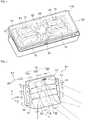
- the lighting device 110 related to the first embodiment includes a first light emitting part 81.
- the lighting device 110 can include a plurality of first light emitting parts 81.
- the lighting device 110 can include a second light emitting part 82.
- the second light emitting part 82 will be described later.
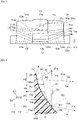
- the first light emitting part 81 includes a first optical part 10 and a first light source part 31.
- the first light source part 31 includes, for example, a light emitting diode (LED).
- the first light source part 31 can include a plurality of light sources, such as a first light source 31a, a second light source 31b, a third light source 31c and the like.
- the first light source 31a, the second light source 31b, and the third light source 31c each includes an LED, for example.
- the first light source 31a is located between the second light source 31b and the third light source 31c. Light is output from each light source.
- the first light source part 31 can be located at the central position of the first light source part 31.
- the position of the first light source part 31 can be substantially the central position of the first light source 31a.
- the first optical part 10 includes a first reflecting part 11 and a second reflecting part 12. As such, the first optical part 10 includes a plurality of reflecting parts. In this example, the first optical part 10 further includes a third reflecting part 13 and a fourth reflecting part 14. At least one portion of the third reflecting part 13 is located between the first reflecting part 11 and the second reflecting part 12. At least one portion of the fourth reflecting part 14 is located between the third reflecting part 13 and the second reflecting part 12. The number of reflecting parts provided in the first optical part 10 can be appropriately determined.
- the first reflecting part 11 includes a first reflecting face 11a
- the second reflecting part 12 includes a second reflecting face 12b.
- the first reflecting part 11 includes a third reflecting face 11c and a fourth reflecting face 11d.
- at least one portion of the first reflecting face 11a is located between the third reflecting face 11c and the fourth reflecting face 11d.
- the second reflecting part 12 includes a fifth reflecting face 12e and a sixth reflecting face 12f.
- at least one portion of the second reflecting face 12b is located between the fifth reflecting face 12e and the sixth reflecting face 12f.
- the number of reflecting faces provided in each of the first reflecting part 11 and the second reflecting part 12 can be appropriately determined.
- the first reflecting part 11 can be located at the central position of the first reflecting part 11.
- the first reflecting part 11 can substantially be located at the center 11ac of the first reflecting face 11a (see FIG. 4 ).
- the second reflecting part 12 can be located at the central position of the second reflecting part 12.
- the position of the second reflecting part 12 can substantially be the center 12bc of the second reflecting face 12b (see FIG. 4 ).
- the direction from the first reflecting part 11 to the second reflecting part 12 is assumed as a first direction D1.
- the direction from the center 11ac of the first reflecting face 11a to the center 12bc of the second reflecting face 12b corresponds to the first direction D1.
- the direction from the first light source part 31 to the second reflecting part 12 is assumed as a second direction D2.
- the first direction D1 crosses the second direction D2.
- the second direction D2 corresponds to the direction from the center of the first light source 31a of the first light source part 31 to the center 12bc of the second reflecting face 12b.
- the direction Dz1 from the first light source part 31 to the first reflecting part 11 is along a first plane which includes the first direction D1 (i.e., the D1-D2 plane) and the second direction D2.
- the direction Dz1 crosses the second direction D2.
- the direction Dz1 from the first light source part 31 to the first reflecting part 11 corresponds to the direction from the central position of the first light source part 31 to the central position of the first reflecting part 11.
- the direction perpendicular to the first plane (the D1-D2 plane) which includes the first direction D1 and the second direction D2 is assumed as a third direction D3.
- the lighting device 110 illuminates, for example, a surface referred to as an illuminated surface.
- the light outgoing from the lighting device 110 is incident on the illuminated surface.
- the illuminated surface can be a road as one example.
- the lighting device is disposed on a lateral face crossing the illuminated surface (i.e., the surface of the road).
- the lateral face is a surface such as a sidewall.
- the road is illuminated by the lighting device 110.
- the direction from the bottom to the top of the lateral face is assumed as a Y-axis direction (see FIG. 2 ).
- the Y-axis direction is, for example, substantially perpendicular to the surface of the road.
- the direction from the bottom edge of the lateral face to the road is assumed as a Z-axis direction (see FIG. 2 ).
- the Z-axis direction corresponds to the direction from the side of the road to the center of the road.
- the direction in which the road extends is assumed as an X-axis direction (see FIG. 2 ).
- the Y-axis direction, the Z-axis direction, and the X-axis direction orthogonal with one another.
- the third direction D3 is along the X-axis direction.
- the first plane (the D1-D2 plane) which includes the first direction D1 and the second direction D2 is , for example, perpendicular to the X-axis direction.
- the first direction D1 is oblique to the Z-axis direction.
- the second direction D2 is also oblique to the Z-axis direction.
- the position of the first reflecting face 11a in the third direction D3 is located between the position of the third reflecting face 11c in the third direction D3 and the position of the fourth reflecting face 11d in the third direction D3.
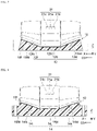
- FIG. 10 corresponds to a cross section taken along the Z-X plane which includes the center of the first reflecting part 11 in the Y-axis direction.
- the first reflecting face 11a in the third direction D3 can practically be at the center 11ac of the first reflecting face 11a in the third direction D3 (see FIG. 3 and FIG. 10 ).
- the third reflecting face 11c in the third direction D3 can practically be at the center 11cc of the third reflecting face 11c in the third direction D3 (see FIG. 3 and FIG. 10 ).
- the position of the fourth reflecting face 11d in the third direction D3 can practically be at the center 11dc of the fourth reflecting face 11d in the third direction D3 (see FIG. 3 and FIG. 10 ).
- the position of the second reflecting face 12b in the third direction D3 is between the position of the fifth reflecting face 12e in the third direction D3 and the position of the sixth reflecting face 12f in the third direction D3.
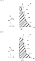
- FIG. 7 corresponds to a cross section taken along the Z-X plane that includes the center of the second reflecting part 12 in the Y-axis direction.
- the position of the second reflecting face 12b in the third direction D3 can practically be at the center 12bc of the second reflecting face 12b in the third direction D3 (see FIG. 3 and FIG. 7 ).
- the position of the fifth reflecting face 12e in the third direction D3 can practically be at the center 12ec of the fifth reflecting face 12e in the third direction D3 (see FIG. 3 and FIG. 7 ).
- the position of the sixth reflecting face 12f in the third direction D3 can practically be at the center 12fc of the sixth reflecting face 12f in the third direction D3 (see FIG. 3 and FIG. 7 ).
- the third reflecting part 13 is located, for example, between the first reflecting part 11 and the second reflecting part 12.
- the third reflecting part 13 includes, for example, a seventh reflecting face 13g, an eighth reflecting face 13h, and a ninth reflecting face 13i.
- at least one portion of the seventh reflecting face 13g is located between the first reflecting face 11a and the second reflecting face 12b.
- At least one portion of the eighth reflecting face 13h is located between the third reflecting face 11c and the fifth reflecting face 12e.
- At least one portion of the ninth reflecting face 13i is located between the fourth reflecting face 11d and the sixth reflecting face 12f.
- the position of the seventh reflecting face 13g in the third direction D3 is between the position of the eighth reflecting face 13h in the third direction D3 and the position of the ninth reflecting face 13i in the third direction D3.
- the number of reflecting faces provided in the third reflecting part 13 can be appropriately determined.
- FIG. 9 corresponds to a cross section taken along the Z-X plane which includes the center of the third reflecting part 13 in the Y-axis direction.
- the position of the seventh reflecting face 13g in the third direction D3 can practically be at the center 13gc of the seventh reflecting face 13g in the third direction D3 (see FIG. 9 ).
- the position of the eighth reflecting face 13h in the third direction D3 can practically be at the center 13hc of the eighth reflecting face 13h in the third direction D3 (see FIG. 9 ).
- the position of the ninth reflecting face 13i in the third direction D3 can practically be at the center 13ic of the ninth reflecting face 13i in the third direction D3 (see FIG. 9 ).
- the fourth reflecting part 14 is located, for example, between the third reflecting part 13 and the second reflecting part 12.
- the fourth reflecting part 14 includes, for example, a tenth reflecting face 14j, an eleventh reflecting face 14k, and a twelfth reflecting face 141.
- at least one portion of the tenth reflecting face 14j is located between the seventh reflecting face 13g and the second reflecting face 12b.
- At least one portion of the eleventh reflecting face 14k is located between the eighth reflecting face 13h and the fifth reflecting face 12e.
- At least one portion of the twelfth reflecting face 141 is located between the ninth reflecting face 13i and the sixth reflecting face 12f.
- the position of the tenth reflecting face 14j in the third direction D3 is between the position of the eleventh reflecting face 14k in the third direction D3 and the position of the twelfth reflecting face 141 in the third direction D3.
- the number of reflecting faces provided in the fourth reflecting part 14 can be appropriately determined.
- FIG. 8 corresponds to a cross section taken along the Z-X plane which includes the center of the fourth reflecting part 14 in the Y-axis direction.
- the position of the tenth reflecting face 14j in the third direction D3 can practically be at the center 14jc of the tenth reflecting face 14j in the third direction D3 (see FIG. 8 ).
- the position of the eleventh reflecting face 14k in the third direction D3 can practically be at the center 14kc of the eleventh reflecting face 14k in the third direction D3 (see FIG. 8 ).
- the position of the twelfth reflecting face 141 in the third direction D3 can practically be at the center 14lc of the twelfth reflecting face 141 in the third direction D3 (see FIG. 8 ).
- the first to fourth reflecting parts 11 to 14 are, for example, discontinuous with one another.
- multiple reflecting faces included in each of the first to fourth reflecting parts 11 to 14 are discontinuous with one another.
- one or more steps are present between multiple reflecting faces included in each of the first to fourth reflecting parts 11 to 14.
- one or more steps are present between the first to fourth reflecting parts 11 to 14.
- a first reflecting film 18f can be used as the first optical part 10.
- the first reflecting film 18f is disposed on the surface of the first member 18M.
- the first member 18M is provided with protrusions and depressions.
- the first reflecting film 18f is disposed on the surface having the protrusions and protrusions.
- the first member 18M can include, for example, a resin, glass, or metal. Resins include, for example, polybutylene terephthalate (PBT). Using a resin can simplify processing.
- the first reflecting film 18f includes a metal film such as an aluminum film, for example. Light is reflected by the surface of the first reflecting film 18f.
- the first to fourth reflecting parts 11 to 14 include the first reflecting film 18f disposed on the surface of the first member 18M.
- the first to fourth reflecting parts 11 to 14 correspond to the surface of the first reflecting film 18f.
- the reflecting faces correspond to the surface of the first reflecting film 18f.
- the light outgoing from the first light source part 31 is incident on the multiple reflecting parts included in the first optical part 10.
- the reflecting parts reflect the light outgoing from the first light emitting part 81.
- the reflected light is incident on the illuminated surface, for example, a road.
- the light outgoing from the first light source part 31 is incident on multiple reflecting faces.
- the reflecting faces reflect the light outgoing from the first light emitting part 81.
- the reflected light is incident on the illuminated surface, for example, a road.
- the distance d1 between the first reflecting part 11 and the first light source part 31 is larger than the distance d2 between the second reflecting part 12 and the first light source part 31.
- the distance d1 for example, corresponds to the distance between the center 11ac of the first reflecting face 11a and the center of the first light source part 31.
- the distance d2 for example, corresponds to the distance between the center 12bc of the second reflecting face 12b and the center of the light source part 31.
- FIG. 11 is a schematic plan view illustrating the reflection of light in the lighting device according to the first embodiment.
- FIG. 12 is a schematic sectional view illustrating the reflection of light in the lighting device according to the first embodiment.
- FIG. 13 is a schematic diagram illustrating light in the lighting device according to the first embodiment.
- a portion of the first outgoing light 31L from the first light source part 31 is reflected by the first reflecting part 11, and then becomes the first-reflecting-part light 11L.
- a portion of the first outgoing light 31L from the first light source part 31 is reflected by the second reflecting part 12, and then becomes the second-reflecting-part light 12L.
- the first-reflecting-part light 11L includes, for example, first-reflecting-face light 11aL which is the first outgoing light 31L from the first light source part 31 reflected by the first reflecting face 11a.
- the second-reflecting-part light 12L includes, for example, second-reflecting-face light 12bL which is the first outgoing light 31L from the first light source part 31 reflected by the second reflecting face 12b.
- the light distribution angle DA1 of the first-reflecting-part light 11L in the first plane is larger than the light distribution angle DA2 of the second-reflecting-part light 12L in the first plane.
- the light distribution angle DA1 corresponds, for example, to the light distribution angle of the first-reflecting-face light 11aL in the first plane (the D1-D2 plane).
- the light distribution angle DA2 corresponds, for example, to the light distribution angle of the second-reflecting-face light 12bL in the first plane (the D1-D2 plane).
- a light distribution angle corresponds to an angle range for one half of the highest intensity of light (full width at half maximum).
- the first reflecting part 11 has a first focal point 11f in the first plane (the D1-D2 plane).
- the distance from the first reflecting part 11 to the first focal point 11f corresponds to the first focal point distance f1 (see FIG. 13 ).
- the first-reflecting-part light 11L is incident on the illuminated surface 91 after advancing through the focal point 11f.
- the second reflecting part 12 has no focal point in the first plane (the D1-D2 plane).
- the focal point distance of the second reflecting part 12 is larger than the first focal point distance f1.
- the first light emitting part 81 allows light (i.e., the first-reflecting-part light 11L, the second-reflecting-part light 12L, and the like) to be incident on the illuminated surface 91 from a side of the illuminated surface 91.
- the first-reflecting-part light 11L is incident on a first illuminated region R1 of the illuminated surface 91.
- the second-reflecting-part light 12L is incident on a second illuminated region R2 of the illuminated surface 91.
- the distance between at least one portion of the first illuminated region R1 and the first light emitting part 81 is smaller than the distance between the second illuminated region R2 and the first light emitting part 81.
- the distance between the first illuminated region R1 and the first light emitting part 81 is smaller than the distance between the second illuminated region R2 and the first light emitting part 81.
- the first-reflecting-part light 11L is incident on the first illuminated region R1 in the illuminated surface 91.
- the second-reflecting-part light 12L is incident on the second illuminated region R2 in the illuminated surface 91.
- the first reflecting part 11 is located farther from the first light source part 31 than the second reflecting part 12 is.
- the second reflecting part 12 is located closer to the first light source part 31 than the first reflecting part 11 is.
- the light distribution angle DA1 of the first-reflecting-part light 11L reflected by the first reflecting part 11 is larger than the light distribution angle DA2 of the second-reflecting-part light 12L reflected by the second reflecting part 12. This can further improve the brightness uniformity in the illuminated surface 91.
- the first-reflecting-part light 11L reflected by the first reflecting part 11 is incident on the first illuminated region R1 that is closer to the first light source part 31, and the second-reflecting-part light 12L reflected by the second reflecting part 12 is incident on the second illuminated region R2 in the illuminated surface 91.
- the brightness of the illuminated regions can be brought closer between closer region to and farther region from the first light source part 31. This can improve the brightness uniformity in the illuminated surface 91.
- a lighting device as a first reference example that illuminates an illuminated surface 91 such as a road from the above.
- the angle of incidence of the light outgoing from the lighting device to the illuminated surface 91 is small.
- the light is incident on the illuminated surface 91 at an angle close to perpendicular to the surface.
- the light is incident on the illuminated surface 91 with a small angle of incidence.
- An automotive headlight for example, can be cited as a second reference example that laterally illuminates an illuminated surface 91 such as a road.
- the angle of incidence of the light outgoing from the headlight to the illuminated surface 91 is relatively large.
- Such a second reference example is designed such that the light distribution angle of the light reflected by a reflecting part located farther from the light source is smaller than the light distribution angle of the light reflected by a reflecting part disposed closer to the light source. It was found that increasing the angle of incidence in such a second reference example made it difficult to improve the brightness uniformity in the illuminated surface 91.
- the automotive headlight design concept may addresses the point of brightly illuminating distant objects, however, generally has a difficulty in providing uniform brightness across a large area from a far region to a close region.
- the embodiment of the present disclosure can achieve brightness uniformity in the illuminated surface 91 even when the first light emitting part 81 allows the light to be incident on the illuminated surface 91 from a side of the illuminated surface 91 with a broad range of angles of incidence.
- the depression angle of the light outgoing from the first light emitting part 81 is in a range of, for example, about 1 to about 40 degrees.
- the depression angle is in a range of about 1 to about 10 degrees.
- brightness uniformity is poor even with depression angles is in a range of 1 to 10 degrees.
- uniform brightness can be achieved over a wide range of depression angles such as from 1 to 40 degrees.
- the light reflected by other reflecting parts is incident on the area between the first illuminated region R1 and the second illuminated region R2.
- a large area can be illuminated with uniform brightness.
- the depression angle of the first-reflecting-part light 11L is larger than the depression angle of the second-reflecting-part light 12L.
- a first angle ⁇ 1 formed by the optical axis 11x of the first-reflecting-part light 11L and the second direction D2 is larger than a second angle ⁇ 2 formed by the optical axis 12x of the second-reflecting-part light 12L and the second direction D2.
- this relationship of angles allows the first-reflecting-part light 11L to be incident on a closer region in the illuminated surface 91, and the second-reflecting-part light 12L to be incident on a farther region in the illuminated surface 91.
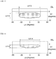
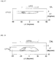
- FIG. 14 to FIG. 21 are schematic diagrams illustrating light distribution angles in the lighting device according to the first embodiment.
- the horizontal axis represents light distribution angles LX (degrees) in the X-axis direction
- the vertical axis represents light distribution angles LY (degrees) in the Y-axis direction
- a light distribution angle LX in the X-axis direction corresponds to a light distribution angle in the third direction D3 perpendicular to the first plane (the D1-D2 plane) which includes the first direction D1 and the second direction D2.
- a light distribution angle LY in the Y-axis direction corresponds to a light distribution angle in the first plane.
- the light distribution angle LX11 of the first-reflecting-part light 11L in the X-axis direction is larger than the light distribution angle LX12 described later.
- the light distribution angle LY11 of the first-reflecting-part light 11L in the Y-axis direction is larger than the light distribution angle LY12 described later.
- the light distribution angle LX12 of the second-reflecting-part light 12L in the X-axis direction is smaller than the light distribution angle LX11.
- the light distribution angle LY12 of the second-reflecting-part light 12L in the Y-axis direction is smaller than the light distribution angle LY11.
- the third-reflecting-part light 13L has a light distribution angle LX13 in the X-axis direction (i.e., the third direction D3) and a light distribution angle LY13 in the Y-axis direction.
- the light distribution angle LX13 is positioned between the light distribution angle LX11 and the light distribution angle LX12.
- the light distribution angle LY13 is positioned between the light distribution angle LY11 and the light distribution angle LY12.
- the fourth-reflecting-part light 14L has a light distribution angle LX14 in the X-axis direction (i.e., the third direction D3) and a light distribution angle LY14 in the Y-axis direction.
- the light distribution angle LX14 is positioned between the light distribution angle LX13 and the light distribution angle LX12.
- the light distribution angle LY14 is positioned between the light distribution angle LY13 and the light distribution angle LY12.
- the light distribution angle LX11 and the light distribution angle LY11 correspond to the entire area of light distribution angles of the light beams reflected by the multiple reflecting faces included in the first reflecting part 11.
- the light distribution angle LX12 and the light distribution angle LY12 correspond to the entire area of light distribution angles of the light reflected by the multiple reflecting faces included in the second reflecting part 12.
- the light distribution angle LX13 and the light distribution angle LY13 correspond to the entire area of light distribution angles of the light reflected by the multiple reflecting faces included in the third reflecting part 13.
- the light distribution angle LX14 and the light distribution angle LY14 correspond to the entire area of light distribution angles of the light reflected by the multiple reflecting faces included in the fourth reflecting part 14.
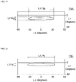
- FIG. 18 illustrates the distribution angles of the first-reflecting-face light 11aL reflected by the first reflecting face 11a.
- FIG. 19 illustrates the distribution angles of the seventh-reflecting-face light 13gL reflected by the seventh reflecting face 13g.
- FIG. 20 illustrates the distribution angles of the tenth-reflecting-face light 14jL reflected by the tenth reflecting face 14j.
- FIG. 21 illustrates the distribution angles of the second-reflecting-face light 12bL reflected by the second reflecting face 12b.
- the first-reflecting-face light 11aL has a light distribution angle LX11a in the X-axis direction (i.e., the third direction D3) and a light distribution angle LY11a in the Y-axis direction.
- the seventh-reflecting-face light 13gL has a light distribution angle LX13g in the X-axis direction (i.e., the third direction D3) and a light distribution angle LY13g in the Y-axis direction.
- LX11a in the X-axis direction
- LY11a in the Y-axis direction.
- the tenth-reflecting-face light 14jL has a light distribution angle LX14j in the X-axis direction (i.e., the third direction D3) and a light distribution angle LY14j in the Y-axis direction.
- the second-reflecting-face light 12bL has a light distribution angle LX12b in the X-axis direction (i.e., the third direction D3) and a light distribution angle LY12b in the Y-axis direction.
- the light distribution angle LX11a is larger than the light distribution angle LX12b.
- the light distribution angle LX11a corresponds to the light distribution angle of the first-reflecting-face light 11aL, which is a portion of the first outgoing light 31L reflected by the first reflecting face 11a, in the third direction D3.
- the light distribution angle LX12b corresponds to the distribution angle of the second-reflecting-face light 12bL, which is a portion of the first outgoing light 31L reflected by the second reflecting face 12b, in the third direction D3.
- the light distribution angle LY11a is larger than the light distribution angle LY12b.
- the light distribution angle LY11a corresponds to the light distribution angle of the first-reflecting-face light 11aL in the first plane (the D1-D2 plane).
- the light distribution angle LY12b corresponds to the light distribution angle of the second-reflecting-face light 12bL in the first plane.
- the light distribution angle LX13g is positioned between the light distribution angle LX11a and the light distribution angle LX12b. In one example, the light distribution angle LY13g is positioned between the light distribution angle LY11a and the light distribution angle LY12b. In one example, the light distribution angle LX14j is positioned between the light distribution angle LX13g and the light distribution angle LX12b. In one example, the light distribution angle LY14j is positioned between the light distribution angle LY13g and the light distribution angle LY12b.
- the first reflecting part 11 has a protrusions shape.
- the first reflecting face 11a is protruded with reference to the third reflecting face 11c.
- the first reflecting face 11a is protruded with reference to the fourth reflecting face 11d.
- the first reflecting part 11 has a protruding shape in at least one of the traveling directions of the first-reflecting-part light 11L (in this example, the direction is along the Z-axis direction, see FIG. 11 ). With such a shape, the first-reflecting-part light 11L spreads widely. This can increase the light distribution angle of the first-reflecting-part light 11L in the X-axis direction.
- the second reflecting part 12 has a depressed shape.
- the second reflecting face 12b is depressed with reference to the fifth reflecting face 12e.
- the second reflecting face 12b is depressed with reference to the sixth reflecting face 12f.
- the second reflecting part 12 has a depressed shape in at least one of the traveling directions of the second-reflecting-part light 12L (in this example, the direction is along the Z-axis direction, see FIG. 11 ).
- the third reflecting part 13 has a depressed shape.
- the third reflecting part 13 has a depressed shape in at least one of the traveling directions of the third-reflecting-part light 13L.
- the fourth reflecting part 14 has a depressed shape.
- the fourth reflecting part 14 has a depressed shape in at least one of the traveling directions of the fourth-reflecting-part light 14L.
- the first reflecting face 11a has a depressed shape.
- the second reflecting face 12b has a depressed shape.
- the seventh reflecting face 13g has a depressed shape.
- the tenth reflecting face 14j has a depressed shape.
- a second plane which includes the third direction D3 is, for example, the X-Z plane.
- the first reflecting face 11a has a protruded shape.
- the second reflecting face 12b has a depressed shape or is substantially planar.
- the third reflecting face 11c has a depressed shape.
- the fourth reflecting face 11d has a depressed shape.
- the third reflecting face 11c has a protrusions shape.
- the fourth reflecting face 11d has a protrusions shape. Such a shape can increase the light distribution angle of the first-reflecting-part light 11L reflected by the first reflecting part 11.
- the first, second, third and fourth reflecting parts 11, 12, 13 and 14 respectively have first, second, third and fourth lengths HI, H2, H3 and H4 along the Y-axis direction.
- the first to fourth lengths H1 to H4 correspond to the heights.
- the first length H1 is greater than the second length H2.
- the third length H3 is smaller than the first length HI, and smaller than the second length H2.
- the fourth length H4 is smaller than the first length HI, and smaller than the second length H2.
- changing the first to fourth lengths H1 to H4 can changes the areas of the first to fourth reflecting parts 11 to 14.
- Increasing the first length H1 can increase the sizes of the reflecting faces, thereby illuminating a wide region near the first light source part 31.
- Increasing the second length H2 to some extent can adequately increase the sizes of the reflecting faces, thereby illuminating a region farther from the first light source part 31 with required brightness.
- the intermediate parts such as the third reflecting part 13 and the fourth reflecting part 14 do not necessarily need large areas because they can receive the effect of the first-reflecting-part light 11L from the first reflecting part 11 or the second-reflecting-part light 12L from the second reflecting part 12.
- a plurality of first light emitting parts 81 can be provided. As shown in FIG. 1 , in one example, the arrangement direction from one of the first light emitting parts 81 to another one of the first light emitting part 81 is along the third direction D3.
- FIG. 1 An example of a second light emitting part 82 will be explained below. As shown in FIG. 1 , in the case of disposing a plurality of first light emitting parts 81, for example, at least a portion of the second light emitting part 82 can be disposed between the first light emitting parts 81.
- FIG. 22 to FIG. 24 are schematic diagrams illustrating a portion of the lighting device according to the first embodiment of the present disclosure.
- FIG. 22 to FIG. 24 each illustrate a second light emitting part 82.
- FIG. 22 is a perspective view.
- FIG. 23 is a sectional view taken along line XXIII-XXIII in FIG. 22 .
- FIG. 24 is a plan view.
- the second light emitting part 82 includes a second optical part 20 and a second light source part 32.
- the second optical part 20 has a second-optical-part reflecting face 21.
- the second-optical-part reflecting face 21 is, for example, a continuously curved surface.
- the second light source part 32 allows the second outgoing light 32L to be incident on the second-optical-part reflecting face 21.
- the second light source part 32 includes, for example, an LED.
- the light from the LED is incident on the second-optical-part reflecting face 21.
- the light reflected by the second-optical-part reflecting face 21 becomes the second-optical-part reflected light 21L.
- the second-optical-part reflected light 21L is incident on the illuminated surface 91.
- the second-optical-part reflecting face 21 has a continuous depressed shape at least in one of the traveling directions of the second-optical-part reflected light 21L.
- a second reflecting film 28f can be used as the second optical part 20.
- the second reflecting film 28f is disposed on the surface of the second member 28M.
- a depression is provided in the second member 28M.
- the second reflecting film 28f is disposed on the surface on which the depression is formed.
- the second member 28M can contain, for example, a resin, glass, or metal.
- Examples of the second reflecting film 28f includes a metal film such as aluminum film. Light is reflected at the surface of the second reflecting film 28f.
- the second-optical-part reflecting face 21 includes, for example, the second reflecting film 28f disposed on the surface of the second member 28M.
- the second-optical-part reflected light 21L spreads in the Y-Z plane. As shown in FIG. 24 , the second-optical-part reflected light 21L spreads in the X-Z plane. The second-optical-part reflected light 21L also spreads in the X-axis direction while advancing along the Z-axis direction.
- FIG. 25 is a schematic diagram illustrating light in a lighting device according to the first embodiment of the present disclosure.
- FIG. 25 illustrates the second-optical-part reflected light 21L outgoing from the second light emitting part 82.
- FIG. 25 illustrates the first illuminated region R1 on which the first-reflecting-part light 11L is incident, and the second illuminated region R2 on which the second-reflecting-part light 12L is incident.
- the position of the first light emitting part 81 is substantially the same as the position of the second light emitting part 82.
- the first light emitting part 81 is omitted in FIG. 25 .
- the lighting device 110 illuminates the illuminated surface 91 from one side of the illuminated surface 91.
- the light outgoing from the first light emitting part 81 e.g., the first-reflecting-part light 11L
- the first light emitting part 81 illuminates the first illuminated region R1.
- the light outgoing from the second light emitting part 82 e.g., the second-optical-part reflected light 21L
- the second light emitting part 82 illuminates the third illuminated region R3.
- At least one portion of the third illuminated region R3 is closer than the first illuminated region R1 with reference to the first light emitting part 81 or the second light emitting part 82.
- the distance between at least one portion of the third illuminated region R3 and the second light emitting part 82 is smaller than the distance between the first illuminated region R1 and the first light emitting part 81.
- the third illuminated region R3, the first illuminated region R1, and the second illuminated region R2 are formed in that order of being the closest to the furthest from the lighting device 110.
- the reflecting parts (e.g., the first reflecting part 11, the second reflecting part 12, and the like) included in the first light emitting part 81 reflect light to allow the reflect light to be incident on the first illuminated region R1.
- the second-optical-part reflecting face 21 included in the second light emitting part 82 reflects light to allow the reflect light to be incident on the third illuminated region R3. Combination of the first light emitting part 81 and the second light emitting part 82, a large area can be illuminated with uniform brightness.
- the first reflecting part 11 is farther from a light source than the second reflecting part 12 is.
- the first-reflecting-part light 11L reflected by the first reflecting part 11 has a larger light distribution angle and a larger depression angle than those of the second-reflecting-part light 12L described later.
- the first-reflecting-part light 11L reflected by the first reflecting part 11 illuminates the first illuminated region R1 located in the middle.
- the second-reflecting-part light 12L reflected by the second reflecting part 12 has a smaller light distribution angle and a smaller depression angle than those of the first-reflecting-part light 11L.
- the second-reflecting-part light 12L reflected by the second-reflecting-part 12 illuminates the second illuminated region R2 located further away.
- the second-optical-part reflected light 21L reflected by the second-optical-part reflecting face 21 of the second light emitting part 82 illuminates the third illuminated region R3 located closer to the second light emitting part 82.
- the brightness unevenness remaining in the light from the first light emitting part 81 is compensated for by the light from the second light emitting part 82, thereby achieving uniform brightness across a large area.
- FIG. 26 is a schematic diagram illustrating the lighting devices according to the first embodiment in use.
- the illuminated surface 91 is a road surface.
- a sidewall 92 meeting the illuminated surface 91 is provided.
- the lighting devices 110 according to the embodiment are disposed, for example, on the sidewall 92.
- the lighting devices 110 are disposed, for example, on the lateral face 92f that meets the illuminated surface 91 to illuminate the road from the side of the road. Accordingly, uniform brightness in the Z-axis direction may be achieved by one lighting device 110.
- a plurality of lighting devices 110 are arranged along the X-axis direction. In the illuminated surface 91, a portion of the light outgoing from one of the lighting devices 110 overlaps with the light outgoing from another one of the lighting devices 110.
- the brightness in the X-axis direction can be made uniform by the plurality of lighting devices 110.
- FIG. 27 is a schematic sectional view illustrating a portion of a lighting device according to a second embodiment of the present disclosure.
- FIG. 27 illustrates a first light emitting part 81A in a lighting device 120 according to the second embodiment.
- FIG. 27 is a cross section corresponding to the cross section shown in FIG. 4 .
- the first light emitting part 81A also includes a first optical part 10 and a first light source part 31.
- the first optical part 10 includes a first member 18M and a first reflecting film 18f.
- the light outgoing from the first light source part 31 transmits through the first member 18M before being incident on the first reflecting film 18f.
- the light reflected by the first reflecting film 18f is incident on the illuminated surface 91.
- the first optical part 10 in this case also includes a plurality of reflecting parts, such as the first reflecting part 11, the second reflecting part 12, and the like.
- the first reflecting film 18f functions as multiple reflecting parts.
- the first optical part 10 can be of a back-face reflection type.
- the reflecting parts in the second embodiment the reflecting parts configured as explained in relation to the first embodiment can be applied.
- the lighting device provided according to the second embodiment can also exhibit an improved brightness uniformity in the illuminated surface.
- FIG. 28 is a schematic sectional view illustrating a portion of a lighting device according to a third embodiment of the present disclosure.
- FIG. 28 illustrates a second light emitting part 82A in a lighting device 130 according to the third embodiment.
- FIG. 28 illustrates a cross section corresponding to the cross section shown in FIG. 23 .
- the second lighting part 82A also includes a second optical part 20 and a second light source part 32.
- the second optical part 20 includes a second member 28M and a second reflecting film 28f.
- the light outgoing from the second light source part 32 transmits through the second member 28M before being incident on the second reflecting film 28f.
- the light reflected by the second reflecting film 28f is incident on the illuminated surface 91.
- the second optical part 20 in this case also has a second-optical-part reflecting face 21.
- the second reflecting film 28f functions as the second-optical-part reflecting face 21.
- the second optical part 20 can be of a back-face reflection type.
- the second-optical-part reflecting face 21 in the third embodiment configured as explained in relation to the first embodiment can be applied.
- the lighting device provided according to the third embodiment can also exhibit an improved brightness uniformity in the illuminated surface.
- the first light emitting part 81A explained in relation to the second embodiment and the second light emitting part 82A explained in relation to the third embodiment can be combined.
- a lighting device 110 is used as the lighting device according to the embodiment.
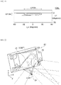
- FIG. 29 is a schematic diagram of the lighting device according to the embodiment in use.
- any of the lighting devices according to the first to third embodiments can illuminate a building 95.
- the illuminated surface 91 is, for example, a wall face 95S of the building 95.
- the light outgoing from the lighting device 110 is incident on the wall face 95S, achieving a substantially uniform brightness at least in a portion of the wall face 95S, for example, in the illuminated region 91E.
- the illuminated region 91E corresponds to the "effective illuminated region".
- the lighting device 110 can be disposed at a distance or far from the ground 96.
- the height of the building 95 corresponds to the Z axis direction.
- the left/right direction of the wall face 95S corresponds to the X axis direction.
- the direction perpendicular to the wall face 95S corresponds to the Y axis direction.
- the length of the illuminated region 91E along the Z axis direction is denoted as length Dh3 (i.e., height).
- the length of the illuminated region 91E along the X axis direction is denoted as length Dx3 (i.e., left/right width). As shown in FIG.
- the angle formed by the line extending in the Z axis direction from the projected position of the emission part 110L on the illuminated surface 91 (i.e., wall face 95S) in the Y axis direction and the line extending from the projected position of the emission part 110L on the illuminated surface 91 (i.e., wall face 95S) in the Y axis direction to one end 91Le of the lower edge 91L of the illuminated region 91 is denoted as angle ⁇ 3.
- FIG. 30 is a schematic lateral face view illustrating the lighting device according to the embodiment in use.
- the distance between the emission part 110L of the lighting device 110 and the illuminated surface 91 (i.e., wall face 95S) along the Y axis direction is denoted as a distance Dy1.
- the distance Dy1 corresponds to the distance to the emission part 110L from the wall face 95S.
- the distance between the lower edge of the illuminated region 91E and the emission part 110L along the Z axis direction is denoted as a length Dh1.
- the distance between the upper edge of the illuminated region 91E and the emission part 110L along the Z axis direction is denoted as a length Dh2.
- the sum of the length Dh1 and the length Dh3 corresponds to the length Dh2.
- angle ⁇ 1 in the Y-Z plane passing the emission part 110L, the angle formed by the illuminated surface 91 (wall face 95S) and the direction, which connects the emission part 110L and the lower edge 91L of the illuminated region 91E, is denoted as angle ⁇ 1.
- angle ⁇ 2 In the Y-Z plane passing the emission part 110L, the angle formed by the illuminated surface 91 (i.e., wall face 95S) and the direction, which connects the emission part 110L and the upper edge 91U of the illuminated region 91E, is denoted as angle ⁇ 2.
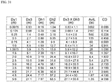
- FIG. 31 is a table showing the characteristics of the lighting device according to the embodiment.
- FIG. 31 shows examples of simulation results of the illuminated region 91E (the "effective illuminated region” where a substantially uniform brightness can be achieved) when the distance Dy1 (i.e., distance from the wall face 95S to the emission part 110L) is changed.
- the range in which one half of the peak illuminance in the illuminated region 91E can be achieved constitutes the outer boundary of the illuminated region 91E.
- the illuminance at the edges of the illuminated region 91E in the height direction thereof referred to as the length Dh3 (i.e., height), and the edges of the illuminated region 91E in the left/right direction thereof referred to as the length Dx3 (i.e., left/right width), is one half of the peak illuminance.
- the illuminance within the illuminated region 91E is substantially uniform, and the illuminance outside of the illuminated region 91E is nonuniform.
- the range in which one half of the peak illuminance in the illuminated region 91E is substantially achieved may be considered as the outer boundary of the illuminated region 91E.
- the angle ⁇ 3 (see FIG. 29 ) is 59.5 degrees.
- the angle ⁇ 1 (see FIG. 30 ) is 32.1 degrees.
- the angle ⁇ 2 ( FIG. 30 ) is 4.5 degrees.
- FIG. 31 also shows average illuminance AvIL and distance coefficient CD.
- Average illuminance AvIL is the average illuminance in the illuminated region 91E.
- Distance coefficient CD is a ratio of a distance Dy1 when the distance Dy1 of 1.0975 m is 1.
- the lengths Dh1, Dh2, Dh3, and Dx3 increase.
- the size of the illuminated region 91E both in the height direction and the left/right direction increases.
- the average illuminance AvIL decreases.
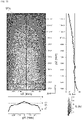
- FIG. 32 and FIG. 33 are schematic diagrams showing the characteristics of the lighting device according to the embodiment.
- illuminance IL in the X-Z plane is shown. Positions pX in the X axis direction and positions in the Z axis direction pZ is defined by using the position of the emission part 110L as a reference.
- the diagrams in FIG. 33 represent enlarged portions of those shown in FIG. 32 .
- the illuminance IL is substantially symmetrical at positions pX on the left and right sides in the X axis direction.
- the illuminance IL declines as the positions pZ is numbered with a greater numeral along the Z axis direction.
- the illuminated region 91E with substantially uniform illuminance is substantially rectangular in shape.
- the size of the illuminated region 91E changes because the illuminated regions 91E shown in both FIG. 32 and FIG. 33 are correlated.
- the distance Dy1 is 1.75 m
- the length Dh1 is 2.79 m
- the length Dh2 is 22.2 m
- the length Dh3 is 19.4 m.
- the average illuminance AvIL in the illuminated region 91E is 11.02 lx.
- the simulation result examples described above are also applicable in the case in which the illuminated surface 91 is a road surface.
- the distance Dy1 corresponds to the distance (i.e., height) from the road surface to the emission part 110L.
- a lighting device with improved brightness uniformity in the illuminated surface can be provided.
- perpendicular and parallel encompass not only being strictly perpendicular and strictly parallel, but also those including manufacturing tolerances, for example, and thus can be substantially perpendicular and substantially parallel.
Landscapes
- Engineering & Computer Science (AREA)
- General Engineering & Computer Science (AREA)
- Non-Portable Lighting Devices Or Systems Thereof (AREA)
Claims (15)
- Beleuchtungsvorrichtung (110, 120, 130), umfassend:ein erstes lichtemittierendes Bauteil (81, 81A), umfassend ein erstes optisches Bauteil (10) und ein Lichtquellenbauteil (31); wobei das erste optische Bauteil (10) ein erstes reflektierendes Bauteil (11) und ein zweites reflektierendes Bauteil (12) umfasst,wobei eine erste Richtung (D1), die sich von dem ersten reflektierenden Bauteil (11) zu dem zweiten reflektierenden Bauteil (12) erstreckt, eine zweite Richtung (D2) kreuzt, die sich von dem ersten Lichtquellenbauteil (31) zu dem zweiten reflektierenden Bauteil (12) erstreckt,wobei sich eine Richtung, die sich von dem ersten Lichtquellenbauteil (31) zu dem ersten reflektierenden Bauteil (11) erstreckt, entlang einer ersten Ebene erstreckt, die die erste Richtung und die zweite Richtung enthält, und die zweite Richtung kreuzt, wobei ein Abstand (d1) zwischen dem ersten reflektierenden Bauteil (11) und dem ersten Lichtquellenbauteil (31) größer ist als ein Abstand (d2) zwischen dem zweiten reflektierenden Bauteil (12) und dem ersten Lichtquellenbauteil (31), und wobei ein Lichtverteilungswinkel (DA1) eines Lichts (11L) des ersten reflektierenden Bauteils, das ein Teil eines ersten ausgehenden Lichts von dem ersten Lichtquellenbauteil (31), reflektiert durch das erste reflektierende Bauteil (11), in der ersten Ebene ist, größer ist als ein Lichtverteilungswinkel (DA2) eines Lichts (12L) des zweiten reflektierenden Bauteils, das ein Teil des ersten ausgehenden Lichts, reflektiert durch das zweite reflektierende Bauteil (12), in der ersten Ebene ist,dadurch gekennzeichnet, dass der Lichtverteilungswinkel (LX11) des Lichts (11L) des ersten reflektierenden Bauteils in einer dritten Richtung (D3) orthogonal zu der ersten Ebene größer ist als ein Lichtverteilungswinkel (LX12) des Lichts (12L) des zweiten reflektierenden Bauteils in der dritten Richtung (D3).
- Beleuchtungsvorrichtung (110, 120, 130) nach Anspruch 1, wobei ein erster Winkel, gebildet durch eine optische Achse des Lichts (11L) des ersten reflektierenden Bauteils und die zweite Richtung, größer ist als ein zweiter Winkel, gebildet durch eine optische Achse des Lichts (12L) des zweiten reflektierenden Bauteils und die zweite Richtung.
- Beleuchtungsvorrichtung (110, 120, 130) nach Anspruch 1, wobeidas erste reflektierenden Bauteil (11) eine erste reflektierende Fläche umfasst,das zweite reflektierende Bauteil (12) eine zweite reflektierende Fläche umfasst, undein Lichtverteilungswinkel eines Lichts der ersten reflektierenden Fläche, das ein Teil des ersten ausgehenden Lichts, reflektiert durch die erste reflektierende Fläche, in der dritten Richtung ist, größer ist als der Lichtverteilungswinkel des Lichts der zweiten reflektierenden Fläche, das ein Teil des ersten ausgehenden Lichts, reflektiert durch die zweite reflektierende Fläche, in der dritten Richtung ist.
- Beleuchtungsvorrichtung (110, 120, 130) nach Anspruch 3, wobei der Lichtverteilungswinkel des Lichts der ersten reflektierenden Fläche in der ersten Ebene größer ist als der Lichtverteilungswinkel des Lichts der zweiten reflektierenden Fläche in der ersten Ebene.
- Beleuchtungsvorrichtung (110, 120, 130) nach Anspruch 3 oder 4, wobeidas erste reflektierende Bauteil (11) ferner eine dritte reflektierende Fläche und eine vierte reflektierende Fläche umfasst, wobei die erste reflektierende Fläche zwischen der dritten reflektierenden Fläche und der vierten reflektierenden Fläche in der dritten Richtung lokalisiert ist, unddas zweite reflektierende Bauteil (12) ferner eine fünfte reflektierende Fläche und eine sechste reflektierende Fläche umfasst, wobei die zweite reflektierende Fläche zwischen der fünften reflektierenden Fläche und der sechsten reflektierenden Fläche in der dritten Richtung lokalisiert ist.
- Beleuchtungsvorrichtung (110, 120, 130) nach Anspruch 5, wobeidas erste reflektierende Bauteil (11) eine Vorsprungsgestalt in wenigstens einer von Ausbreitungsrichtungen des Lichts (11L) des ersten reflektierenden Bauteils hat, unddas zweite reflektierende Bauteil (12) eine Vertiefungsgestalt in wenigstens einer von Ausbreitungsrichtungen des Lichts (12L) des zweiten reflektierenden Bauteils hat.
- Beleuchtungsvorrichtung (110, 120, 130) nach Anspruch 5, wobeidie erste reflektierende Fläche mit Bezug zu der dritten reflektierenden Fläche vorspringt, und mit Bezug zu der vierten reflektierenden Fläche vorspringt, unddie zweite reflektierende Fläche mit Bezug zu der fünften reflektierenden Fläche vertieft ist, unddie zweite reflektierende Fläche mit Bezug zu der sechsten reflektierenden Fläche vertieft ist.
- Beleuchtungsvorrichtung (110, 120, 130) nach Anspruch 5, wobeidie erste reflektierende Fläche eine vertiefte Gestalt in einem Schnitt hat, der parallel zur ersten Ebene geschnitten ist,die erste reflektierende Fläche eine Vorsprungsgestalt in einem Schnitt hat, der parallel zur zweiten Ebene geschnitten ist, der die dritte Richtung enthält,die zweite reflektierende Fläche eine vertiefte Gestalt in einem Schnitt hat, der parallel zur ersten Ebene geschnitten ist, unddie zweite reflektierende Fläche eine vertiefte Gestalt in einem Schnitt hat, der parallel zur zweiten Ebene geschnitten ist.
- Beleuchtungsvorrichtung (110, 120, 130) nach Anspruch 8, wobeidie dritte reflektierende Fläche eine vertiefte Gestalt in einem Schnitt hat, der parallel zur ersten Ebene geschnitten ist,die dritte reflektierende Fläche eine Vorsprungsgestalt in einem Schnitt hat, der parallel zur zweiten Ebene geschnitten ist,die vierte reflektierende Fläche eine vertiefte Gestalt in einem Schnitt hat, der parallel zur ersten Ebene geschnitten ist, unddie vierte reflektierende Fläche eine Vorsprungsgestalt in einem Schnitt hat, der parallel zur zweiten Ebene geschnitten ist.
- Beleuchtungsvorrichtung (110, 120, 130) nach einem der vorhergehenden Ansprüche, wobeidas erste optische Bauteil (10) ferner ein drittes reflektierendes Bauteil umfasst, undwenigstens ein Bereich des dritten reflektierenden Bauteils zwischen dem ersten reflektierenden Bauteil (11) und dem zweiten reflektierenden Bauteil (12) lokalisiert ist.
- Beleuchtungsvorrichtung (110, 120, 130) nach Anspruch 10, wobeidas erste optische Bauteil (10) ferner ein viertes reflektierendes Bauteil umfasst, undwenigstens ein Bereich des vierten reflektierenden Bauteils zwischen dem dritten reflektierenden Bauteil und dem zweiten reflektierenden Bauteil (12) lokalisiert ist.
- Beleuchtungsvorrichtung (110, 120, 130) nach einem der vorhergehenden Ansprüche, wobeidas erste optische Bauteil (10) ein erstes Element umfasst, unddas erste reflektierende Bauteil (11) und das zweite reflektierende Bauteil (12) einen ersten reflektierenden Film umfassen, der auf der Oberfläche des ersten Elements angeordnet ist.
- Beleuchtungsvorrichtung (110, 120, 130) nach einem der vorhergehenden Ansprüche, wobeidas erste lichtemittierende Bauteil (81, 81A) eine beleuchtete Oberfläche von einer Seite der beleuchteten Oberfläche beleuchtet,das Licht des ersten lichtreflektierenden Bauteils auf eine erste beleuchtete Region der beleuchteten Oberfläche einfällt,das Licht (12L) des zweiten reflektierenden Bauteils auf eine zweite beleuchtete Region der beleuchteten Oberfläche einfällt, undein Abstand zwischen wenigstens einem Bereich der ersten beleuchteten Region und dem ersten lichtemittierenden Bauteil (81, 81A) kleiner ist als ein Abstand zwischen der zweiten beleuchteten Region und dem ersten lichtemittierenden Bauteil (81, 81A).
- Beleuchtungsvorrichtung (110, 120, 130) nach einem der vorhergehenden Ansprüche, ferner umfassend:
ein zweites lichtemittierendes Bauteil, umfassend:ein zweites optisches Bauteil, das eine reflektierende Fläche des zweiten optischen Bauteils umfasst, die kontinuierlich gekrümmt ist, undein zweites Lichtquellenbauteil (32), das ermöglicht, dass ein zweites ausgehendes Licht auf die reflektierende Fläche des zweiten optischen Bauteils einfällt. - Beleuchtungsvorrichtung (110, 120, 130) nach Anspruch 14, wobeidie Beleuchtungsvorrichtung die beleuchtete Oberfläche von einer Seite der beleuchteten Oberfläche beleuchtet,das erste lichtemittierende Bauteil (81, 81A) die erste beleuchtete Region der beleuchteten Oberfläche beleuchtet,das zweite lichtemittierende Teil eine dritte beleuchtete Region der beleuchteten Oberfläche beleuchtet, undein Abstand zwischen wenigstens einem Bereich der dritten beleuchteten Region und dem zweiten lichtemittierenden Bauteil kleiner ist als ein Abstand zwischen der ersten beleuchteten Region und dem ersten lichtemittierenden Bauteil (81, 81A).
Applications Claiming Priority (2)
| Application Number | Priority Date | Filing Date | Title |
|---|---|---|---|
| JP2019144826 | 2019-08-06 | ||
| JP2020088636A JP7480466B2 (ja) | 2019-08-06 | 2020-05-21 | 照明装置 |
Publications (2)
| Publication Number | Publication Date |
|---|---|
| EP3772610A1 EP3772610A1 (de) | 2021-02-10 |
| EP3772610B1 true EP3772610B1 (de) | 2022-04-20 |
Family
ID=71950464
Family Applications (1)
| Application Number | Title | Priority Date | Filing Date |
|---|---|---|---|
| EP20189537.2A Active EP3772610B1 (de) | 2019-08-06 | 2020-08-05 | Beleuchtungsvorrichtung |
Country Status (4)
| Country | Link |
|---|---|
| US (1) | US11359792B2 (de) |
| EP (1) | EP3772610B1 (de) |
| CN (1) | CN112344293B (de) |
| MY (1) | MY205207A (de) |
Families Citing this family (4)
| Publication number | Priority date | Publication date | Assignee | Title |
|---|---|---|---|---|
| JP7402119B2 (ja) * | 2020-05-27 | 2023-12-20 | 株式会社小糸製作所 | 車両用灯具 |
| US11187393B1 (en) * | 2020-12-30 | 2021-11-30 | Valeo Vision | Light system with cut-off |
| CN113606558B (zh) * | 2021-07-12 | 2023-07-14 | 宁波公牛光电科技有限公司 | 光学结构和灯结构 |
| CN118640433B (zh) * | 2024-06-07 | 2025-03-21 | 珠海和其光照明科技有限公司 | 照明系统及照明装置 |
Family Cites Families (29)
| Publication number | Priority date | Publication date | Assignee | Title |
|---|---|---|---|---|
| US4694382A (en) * | 1986-12-23 | 1987-09-15 | Hubbell Incorporated | Reflector for roadway lighting luminaire |
| JP3145930B2 (ja) | 1996-08-02 | 2001-03-12 | 株式会社小糸製作所 | 車輌用前照灯 |
| AU2001214374A1 (en) | 2000-10-23 | 2002-05-06 | Steven C. Donner | Light fixture |
| US6508574B1 (en) | 2000-10-23 | 2003-01-21 | Allied Lighting Systems, Inc. | Light fixture |
| JP4204757B2 (ja) | 2001-02-19 | 2009-01-07 | 株式会社小糸製作所 | 車両用前照灯 |
| JP3919655B2 (ja) | 2002-12-02 | 2007-05-30 | スタンレー電気株式会社 | 車両用灯具 |
| JP2005166371A (ja) * | 2003-12-01 | 2005-06-23 | Ichikoh Ind Ltd | 車両用灯具 |
| JP2009277482A (ja) | 2008-05-14 | 2009-11-26 | Ichikoh Ind Ltd | 車両用灯具 |
| JP4582190B2 (ja) | 2008-05-14 | 2010-11-17 | 市光工業株式会社 | 車両用灯具 |
| JP4735664B2 (ja) | 2008-05-14 | 2011-07-27 | 市光工業株式会社 | 車両用灯具 |
| US8292480B2 (en) | 2008-07-10 | 2012-10-23 | Koito Manufacturing Co., Ltd. | Lamp including main reflector, sub-reflector and LED assembly |
| JP5210062B2 (ja) | 2008-07-10 | 2013-06-12 | 株式会社小糸製作所 | 灯具 |
| JP5210061B2 (ja) | 2008-07-10 | 2013-06-12 | 株式会社小糸製作所 | 灯具 |
| DE102011081349A1 (de) | 2011-05-25 | 2012-11-29 | Dilitronics Gmbh | Reflektor für eine strassenlampe |
| CN202101152U (zh) | 2011-05-27 | 2012-01-04 | 厦门安赫光电科技有限公司 | 一种适用于高效气体放电灯的反光罩 |
| CN102322614B (zh) * | 2011-08-26 | 2013-11-27 | 上海三思电子工程有限公司 | 用于led光源的反射镜设计方法 |
| US9857056B2 (en) * | 2012-03-08 | 2018-01-02 | Triplet Music Products Inc. | Uniform lighting system |
| CN103994397A (zh) * | 2013-02-20 | 2014-08-20 | 海洋王(东莞)照明科技有限公司 | 一种灯具及其反射器 |
| US9353922B2 (en) * | 2014-02-07 | 2016-05-31 | Pinnacle Architectural Lighting | Wall wash light fixture and method for lighting a wall |
| EP2947384B1 (de) * | 2014-05-23 | 2017-08-30 | OSRAM GmbH | Reflektor für beleuchtungsvorrichtungen, entsprechende beleuchtungsvorrichtung und verfahren |
| CN106574763B (zh) * | 2014-08-11 | 2020-04-07 | 株式会社小糸制作所 | 车辆用前照灯 |
| US9458972B1 (en) * | 2014-10-17 | 2016-10-04 | Ketra, Inc. | Asymmetric linear LED luminaire design for uniform illuminance and color |
| JP2017103189A (ja) * | 2015-12-04 | 2017-06-08 | パナソニックIpマネジメント株式会社 | 前照灯及び移動体 |
| JP6571506B2 (ja) | 2015-12-08 | 2019-09-04 | 株式会社小糸製作所 | 車両用灯具 |
| EP3736487B1 (de) | 2016-04-29 | 2022-02-16 | LG Innotek Co., Ltd. | Beleuchtungsmodul und beleuchtungsvorrichtung mit diesem modul |
| JP6912914B2 (ja) | 2017-03-29 | 2021-08-04 | コイズミ照明株式会社 | 照明器具 |
| JP6902704B2 (ja) | 2017-06-08 | 2021-07-14 | パナソニックIpマネジメント株式会社 | 道路照明器具 |
| JP7247458B2 (ja) | 2018-03-01 | 2023-03-29 | 市光工業株式会社 | 車両用灯具 |
| JP7069835B2 (ja) | 2018-03-01 | 2022-05-18 | 市光工業株式会社 | 車両用灯具 |
-
2020
- 2020-08-05 EP EP20189537.2A patent/EP3772610B1/de active Active
- 2020-08-06 MY MYPI2020004038A patent/MY205207A/en unknown
- 2020-08-06 CN CN202010781739.6A patent/CN112344293B/zh active Active
- 2020-08-06 US US16/987,009 patent/US11359792B2/en active Active
Also Published As
| Publication number | Publication date |
|---|---|
| MY205207A (en) | 2024-10-07 |
| US11359792B2 (en) | 2022-06-14 |
| EP3772610A1 (de) | 2021-02-10 |
| CN112344293B (zh) | 2023-12-08 |
| CN112344293A (zh) | 2021-02-09 |
| US20210041083A1 (en) | 2021-02-11 |
Similar Documents
| Publication | Publication Date | Title |
|---|---|---|
| EP3772610B1 (de) | Beleuchtungsvorrichtung | |
| US9684110B2 (en) | Lighting device for vehicles | |
| EP3480514A1 (de) | Fahrzeuglampe | |
| EP3163155B1 (de) | Optisches streulichtverteilungssystem und fahrzeugbeleuchtungsvorrichtung | |
| EP2202453A2 (de) | Fahrzeugscheinwerfer | |
| US20180356582A1 (en) | Light-guiding optical system | |
| US10725212B2 (en) | Lens | |
| CN102095127A (zh) | 照明装置 | |
| JP2003294954A (ja) | 導光板 | |
| JP5229023B2 (ja) | 車両用灯具 | |
| JP5708991B2 (ja) | 車両用灯具及び車両用灯具に用いられる導光レンズ | |
| JP6114956B2 (ja) | 導光体、照明装置、および画像読取装置 | |
| EP3135989A1 (de) | Fahrzeug lichtleiter und fahrzeuglampe | |
| JP2010129311A (ja) | 車両用灯具 | |
| US20210396980A1 (en) | An optical device for modifying light distribution | |
| EP2208924B1 (de) | Seitenreflektor | |
| WO2014083839A1 (ja) | 導光部材 | |
| JP7480466B2 (ja) | 照明装置 | |
| CN208901313U (zh) | 配光构件、照明装置、信号指示装置和机动车辆 | |
| CN112628688A (zh) | 光学透镜结构 | |
| JP2010205418A (ja) | 車両用灯具 | |
| JP2015176727A (ja) | 車両用灯具及びレンズ体 | |
| JP6751452B2 (ja) | 面状照明装置 | |
| JP4428664B2 (ja) | 導光板 | |
| CN120215009A (zh) | 导光板、背光模组及显示装置 |
Legal Events
| Date | Code | Title | Description |
|---|---|---|---|
| PUAI | Public reference made under article 153(3) epc to a published international application that has entered the european phase |
Free format text: ORIGINAL CODE: 0009012 |
|
| STAA | Information on the status of an ep patent application or granted ep patent |
Free format text: STATUS: THE APPLICATION HAS BEEN PUBLISHED |
|
| AK | Designated contracting states |
Kind code of ref document: A1 Designated state(s): AL AT BE BG CH CY CZ DE DK EE ES FI FR GB GR HR HU IE IS IT LI LT LU LV MC MK MT NL NO PL PT RO RS SE SI SK SM TR |
|
| AX | Request for extension of the european patent |
Extension state: BA ME |
|
| STAA | Information on the status of an ep patent application or granted ep patent |
Free format text: STATUS: REQUEST FOR EXAMINATION WAS MADE |
|
| 17P | Request for examination filed |
Effective date: 20210628 |
|
| RBV | Designated contracting states (corrected) |
Designated state(s): AL AT BE BG CH CY CZ DE DK EE ES FI FR GB GR HR HU IE IS IT LI LT LU LV MC MK MT NL NO PL PT RO RS SE SI SK SM TR |
|
| RIC1 | Information provided on ipc code assigned before grant |
Ipc: F21Y 115/10 20160101ALN20211020BHEP Ipc: F21W 131/107 20060101ALN20211020BHEP Ipc: F21W 131/103 20060101ALN20211020BHEP Ipc: F21V 7/09 20060101ALI20211020BHEP Ipc: F21V 7/00 20060101AFI20211020BHEP |
|
| GRAP | Despatch of communication of intention to grant a patent |
Free format text: ORIGINAL CODE: EPIDOSNIGR1 |
|
| STAA | Information on the status of an ep patent application or granted ep patent |
Free format text: STATUS: GRANT OF PATENT IS INTENDED |
|
| RIC1 | Information provided on ipc code assigned before grant |
Ipc: F21Y 115/10 20160101ALN20211110BHEP Ipc: F21W 131/107 20060101ALN20211110BHEP Ipc: F21W 131/103 20060101ALN20211110BHEP Ipc: F21V 7/09 20060101ALI20211110BHEP Ipc: F21V 7/00 20060101AFI20211110BHEP |
|
| INTG | Intention to grant announced |
Effective date: 20211206 |
|
| GRAS | Grant fee paid |
Free format text: ORIGINAL CODE: EPIDOSNIGR3 |
|
| GRAA | (expected) grant |
Free format text: ORIGINAL CODE: 0009210 |
|
| STAA | Information on the status of an ep patent application or granted ep patent |
Free format text: STATUS: THE PATENT HAS BEEN GRANTED |
|
| AK | Designated contracting states |
Kind code of ref document: B1 Designated state(s): AL AT BE BG CH CY CZ DE DK EE ES FI FR GB GR HR HU IE IS IT LI LT LU LV MC MK MT NL NO PL PT RO RS SE SI SK SM TR |
|
| REG | Reference to a national code |
Ref country code: GB Ref legal event code: FG4D |
|
| REG | Reference to a national code |
Ref country code: CH Ref legal event code: EP |
|
| REG | Reference to a national code |
Ref country code: IE Ref legal event code: FG4D |
|
| REG | Reference to a national code |
Ref country code: DE Ref legal event code: R096 Ref document number: 602020002739 Country of ref document: DE |
|
| REG | Reference to a national code |
Ref country code: AT Ref legal event code: REF Ref document number: 1485409 Country of ref document: AT Kind code of ref document: T Effective date: 20220515 |
|
| REG | Reference to a national code |
Ref country code: LT Ref legal event code: MG9D |
|
| REG | Reference to a national code |
Ref country code: NL Ref legal event code: MP Effective date: 20220420 |
|
| REG | Reference to a national code |
Ref country code: AT Ref legal event code: MK05 Ref document number: 1485409 Country of ref document: AT Kind code of ref document: T Effective date: 20220420 |
|
| PG25 | Lapsed in a contracting state [announced via postgrant information from national office to epo] |
Ref country code: NL Free format text: LAPSE BECAUSE OF FAILURE TO SUBMIT A TRANSLATION OF THE DESCRIPTION OR TO PAY THE FEE WITHIN THE PRESCRIBED TIME-LIMIT Effective date: 20220420 |
|
| PG25 | Lapsed in a contracting state [announced via postgrant information from national office to epo] |
Ref country code: SE Free format text: LAPSE BECAUSE OF FAILURE TO SUBMIT A TRANSLATION OF THE DESCRIPTION OR TO PAY THE FEE WITHIN THE PRESCRIBED TIME-LIMIT Effective date: 20220420 Ref country code: PT Free format text: LAPSE BECAUSE OF FAILURE TO SUBMIT A TRANSLATION OF THE DESCRIPTION OR TO PAY THE FEE WITHIN THE PRESCRIBED TIME-LIMIT Effective date: 20220822 Ref country code: NO Free format text: LAPSE BECAUSE OF FAILURE TO SUBMIT A TRANSLATION OF THE DESCRIPTION OR TO PAY THE FEE WITHIN THE PRESCRIBED TIME-LIMIT Effective date: 20220720 Ref country code: LT Free format text: LAPSE BECAUSE OF FAILURE TO SUBMIT A TRANSLATION OF THE DESCRIPTION OR TO PAY THE FEE WITHIN THE PRESCRIBED TIME-LIMIT Effective date: 20220420 Ref country code: HR Free format text: LAPSE BECAUSE OF FAILURE TO SUBMIT A TRANSLATION OF THE DESCRIPTION OR TO PAY THE FEE WITHIN THE PRESCRIBED TIME-LIMIT Effective date: 20220420 Ref country code: GR Free format text: LAPSE BECAUSE OF FAILURE TO SUBMIT A TRANSLATION OF THE DESCRIPTION OR TO PAY THE FEE WITHIN THE PRESCRIBED TIME-LIMIT Effective date: 20220721 Ref country code: FI Free format text: LAPSE BECAUSE OF FAILURE TO SUBMIT A TRANSLATION OF THE DESCRIPTION OR TO PAY THE FEE WITHIN THE PRESCRIBED TIME-LIMIT Effective date: 20220420 Ref country code: ES Free format text: LAPSE BECAUSE OF FAILURE TO SUBMIT A TRANSLATION OF THE DESCRIPTION OR TO PAY THE FEE WITHIN THE PRESCRIBED TIME-LIMIT Effective date: 20220420 Ref country code: BG Free format text: LAPSE BECAUSE OF FAILURE TO SUBMIT A TRANSLATION OF THE DESCRIPTION OR TO PAY THE FEE WITHIN THE PRESCRIBED TIME-LIMIT Effective date: 20220720 Ref country code: AT Free format text: LAPSE BECAUSE OF FAILURE TO SUBMIT A TRANSLATION OF THE DESCRIPTION OR TO PAY THE FEE WITHIN THE PRESCRIBED TIME-LIMIT Effective date: 20220420 |
|
| PG25 | Lapsed in a contracting state [announced via postgrant information from national office to epo] |
Ref country code: RS Free format text: LAPSE BECAUSE OF FAILURE TO SUBMIT A TRANSLATION OF THE DESCRIPTION OR TO PAY THE FEE WITHIN THE PRESCRIBED TIME-LIMIT Effective date: 20220420 Ref country code: PL Free format text: LAPSE BECAUSE OF FAILURE TO SUBMIT A TRANSLATION OF THE DESCRIPTION OR TO PAY THE FEE WITHIN THE PRESCRIBED TIME-LIMIT Effective date: 20220420 Ref country code: LV Free format text: LAPSE BECAUSE OF FAILURE TO SUBMIT A TRANSLATION OF THE DESCRIPTION OR TO PAY THE FEE WITHIN THE PRESCRIBED TIME-LIMIT Effective date: 20220420 Ref country code: IS Free format text: LAPSE BECAUSE OF FAILURE TO SUBMIT A TRANSLATION OF THE DESCRIPTION OR TO PAY THE FEE WITHIN THE PRESCRIBED TIME-LIMIT Effective date: 20220820 |
|
| REG | Reference to a national code |
Ref country code: DE Ref legal event code: R097 Ref document number: 602020002739 Country of ref document: DE |
|
| PG25 | Lapsed in a contracting state [announced via postgrant information from national office to epo] |
Ref country code: SM Free format text: LAPSE BECAUSE OF FAILURE TO SUBMIT A TRANSLATION OF THE DESCRIPTION OR TO PAY THE FEE WITHIN THE PRESCRIBED TIME-LIMIT Effective date: 20220420 Ref country code: SK Free format text: LAPSE BECAUSE OF FAILURE TO SUBMIT A TRANSLATION OF THE DESCRIPTION OR TO PAY THE FEE WITHIN THE PRESCRIBED TIME-LIMIT Effective date: 20220420 Ref country code: RO Free format text: LAPSE BECAUSE OF FAILURE TO SUBMIT A TRANSLATION OF THE DESCRIPTION OR TO PAY THE FEE WITHIN THE PRESCRIBED TIME-LIMIT Effective date: 20220420 Ref country code: EE Free format text: LAPSE BECAUSE OF FAILURE TO SUBMIT A TRANSLATION OF THE DESCRIPTION OR TO PAY THE FEE WITHIN THE PRESCRIBED TIME-LIMIT Effective date: 20220420 Ref country code: DK Free format text: LAPSE BECAUSE OF FAILURE TO SUBMIT A TRANSLATION OF THE DESCRIPTION OR TO PAY THE FEE WITHIN THE PRESCRIBED TIME-LIMIT Effective date: 20220420 Ref country code: CZ Free format text: LAPSE BECAUSE OF FAILURE TO SUBMIT A TRANSLATION OF THE DESCRIPTION OR TO PAY THE FEE WITHIN THE PRESCRIBED TIME-LIMIT Effective date: 20220420 |
|
| PLBE | No opposition filed within time limit |
Free format text: ORIGINAL CODE: 0009261 |
|
| STAA | Information on the status of an ep patent application or granted ep patent |
Free format text: STATUS: NO OPPOSITION FILED WITHIN TIME LIMIT |
|
| 26N | No opposition filed |
Effective date: 20230123 |
|
| PG25 | Lapsed in a contracting state [announced via postgrant information from national office to epo] |
Ref country code: MC Free format text: LAPSE BECAUSE OF FAILURE TO SUBMIT A TRANSLATION OF THE DESCRIPTION OR TO PAY THE FEE WITHIN THE PRESCRIBED TIME-LIMIT Effective date: 20220420 Ref country code: AL Free format text: LAPSE BECAUSE OF FAILURE TO SUBMIT A TRANSLATION OF THE DESCRIPTION OR TO PAY THE FEE WITHIN THE PRESCRIBED TIME-LIMIT Effective date: 20220420 |
|
| PG25 | Lapsed in a contracting state [announced via postgrant information from national office to epo] |
Ref country code: LU Free format text: LAPSE BECAUSE OF NON-PAYMENT OF DUE FEES Effective date: 20220805 |
|
| REG | Reference to a national code |
Ref country code: BE Ref legal event code: MM Effective date: 20220831 |
|
| PG25 | Lapsed in a contracting state [announced via postgrant information from national office to epo] |
Ref country code: SI Free format text: LAPSE BECAUSE OF FAILURE TO SUBMIT A TRANSLATION OF THE DESCRIPTION OR TO PAY THE FEE WITHIN THE PRESCRIBED TIME-LIMIT Effective date: 20220420 |
|
| P01 | Opt-out of the competence of the unified patent court (upc) registered |
Effective date: 20230522 |
|
| PG25 | Lapsed in a contracting state [announced via postgrant information from national office to epo] |
Ref country code: IE Free format text: LAPSE BECAUSE OF NON-PAYMENT OF DUE FEES Effective date: 20220805 |
|
| PG25 | Lapsed in a contracting state [announced via postgrant information from national office to epo] |
Ref country code: BE Free format text: LAPSE BECAUSE OF NON-PAYMENT OF DUE FEES Effective date: 20220831 |
|
| PG25 | Lapsed in a contracting state [announced via postgrant information from national office to epo] |
Ref country code: IT Free format text: LAPSE BECAUSE OF FAILURE TO SUBMIT A TRANSLATION OF THE DESCRIPTION OR TO PAY THE FEE WITHIN THE PRESCRIBED TIME-LIMIT Effective date: 20220420 |
|
| REG | Reference to a national code |
Ref country code: CH Ref legal event code: PL |
|
| PG25 | Lapsed in a contracting state [announced via postgrant information from national office to epo] |
Ref country code: CY Free format text: LAPSE BECAUSE OF FAILURE TO SUBMIT A TRANSLATION OF THE DESCRIPTION OR TO PAY THE FEE WITHIN THE PRESCRIBED TIME-LIMIT Effective date: 20220420 Ref country code: CH Free format text: LAPSE BECAUSE OF NON-PAYMENT OF DUE FEES Effective date: 20230831 |
|
| PG25 | Lapsed in a contracting state [announced via postgrant information from national office to epo] |
Ref country code: MK Free format text: LAPSE BECAUSE OF FAILURE TO SUBMIT A TRANSLATION OF THE DESCRIPTION OR TO PAY THE FEE WITHIN THE PRESCRIBED TIME-LIMIT Effective date: 20220420 Ref country code: HU Free format text: LAPSE BECAUSE OF FAILURE TO SUBMIT A TRANSLATION OF THE DESCRIPTION OR TO PAY THE FEE WITHIN THE PRESCRIBED TIME-LIMIT; INVALID AB INITIO Effective date: 20200805 |
|
| PG25 | Lapsed in a contracting state [announced via postgrant information from national office to epo] |
Ref country code: MT Free format text: LAPSE BECAUSE OF FAILURE TO SUBMIT A TRANSLATION OF THE DESCRIPTION OR TO PAY THE FEE WITHIN THE PRESCRIBED TIME-LIMIT Effective date: 20220420 |
|
| PG25 | Lapsed in a contracting state [announced via postgrant information from national office to epo] |
Ref country code: BG Free format text: LAPSE BECAUSE OF FAILURE TO SUBMIT A TRANSLATION OF THE DESCRIPTION OR TO PAY THE FEE WITHIN THE PRESCRIBED TIME-LIMIT Effective date: 20220420 |
|
| PG25 | Lapsed in a contracting state [announced via postgrant information from national office to epo] |
Ref country code: BG Free format text: LAPSE BECAUSE OF FAILURE TO SUBMIT A TRANSLATION OF THE DESCRIPTION OR TO PAY THE FEE WITHIN THE PRESCRIBED TIME-LIMIT Effective date: 20220420 |
|
| PGFP | Annual fee paid to national office [announced via postgrant information from national office to epo] |
Ref country code: DE Payment date: 20250702 Year of fee payment: 6 |
|
| PGFP | Annual fee paid to national office [announced via postgrant information from national office to epo] |
Ref country code: GB Payment date: 20250703 Year of fee payment: 6 |
|
| PGFP | Annual fee paid to national office [announced via postgrant information from national office to epo] |
Ref country code: FR Payment date: 20250703 Year of fee payment: 6 |
|
| PG25 | Lapsed in a contracting state [announced via postgrant information from national office to epo] |
Ref country code: TR Free format text: LAPSE BECAUSE OF FAILURE TO SUBMIT A TRANSLATION OF THE DESCRIPTION OR TO PAY THE FEE WITHIN THE PRESCRIBED TIME-LIMIT Effective date: 20220420 |