EP3771764A1 - Dispositif et procédé de fabrication d'un tissu non tissé - Google Patents
Dispositif et procédé de fabrication d'un tissu non tissé Download PDFInfo
- Publication number
- EP3771764A1 EP3771764A1 EP19189231.4A EP19189231A EP3771764A1 EP 3771764 A1 EP3771764 A1 EP 3771764A1 EP 19189231 A EP19189231 A EP 19189231A EP 3771764 A1 EP3771764 A1 EP 3771764A1
- Authority
- EP
- European Patent Office
- Prior art keywords
- hot air
- nonwoven web
- conveyor
- consolidation
- fibers
- Prior art date
- Legal status (The legal status is an assumption and is not a legal conclusion. Google has not performed a legal analysis and makes no representation as to the accuracy of the status listed.)
- Granted
Links
- 239000004745 nonwoven fabric Substances 0.000 title claims abstract description 38
- 238000000034 method Methods 0.000 title claims description 35
- 238000007596 consolidation process Methods 0.000 claims abstract description 146
- 238000009987 spinning Methods 0.000 claims abstract description 107
- 239000000835 fiber Substances 0.000 claims abstract description 80
- 238000000151 deposition Methods 0.000 claims abstract description 62
- 238000001816 cooling Methods 0.000 claims description 27
- 238000003860 storage Methods 0.000 claims description 15
- 238000004519 manufacturing process Methods 0.000 claims description 14
- 238000012546 transfer Methods 0.000 claims description 14
- -1 polyethylene Polymers 0.000 description 16
- 238000005192 partition Methods 0.000 description 14
- 229920000098 polyolefin Polymers 0.000 description 9
- 239000004698 Polyethylene Substances 0.000 description 8
- 229920000573 polyethylene Polymers 0.000 description 8
- 229920000139 polyethylene terephthalate Polymers 0.000 description 7
- 239000005020 polyethylene terephthalate Substances 0.000 description 7
- 229920000728 polyester Polymers 0.000 description 6
- 239000004743 Polypropylene Substances 0.000 description 5
- 229920003023 plastic Polymers 0.000 description 5
- 239000004033 plastic Substances 0.000 description 5
- 229920001155 polypropylene Polymers 0.000 description 5
- 230000007704 transition Effects 0.000 description 5
- 230000000694 effects Effects 0.000 description 4
- 239000012815 thermoplastic material Substances 0.000 description 4
- 238000005299 abrasion Methods 0.000 description 3
- 239000010410 layer Substances 0.000 description 3
- 239000000178 monomer Substances 0.000 description 3
- 229920000747 poly(lactic acid) Polymers 0.000 description 3
- 229920001707 polybutylene terephthalate Polymers 0.000 description 3
- 238000011144 upstream manufacturing Methods 0.000 description 3
- 238000002788 crimping Methods 0.000 description 2
- 239000007789 gas Substances 0.000 description 2
- 238000010438 heat treatment Methods 0.000 description 2
- 238000007726 management method Methods 0.000 description 2
- 238000005259 measurement Methods 0.000 description 2
- 238000002844 melting Methods 0.000 description 2
- 230000008018 melting Effects 0.000 description 2
- 239000000203 mixture Substances 0.000 description 2
- 229920000642 polymer Polymers 0.000 description 2
- 229920001634 Copolyester Polymers 0.000 description 1
- 238000000354 decomposition reaction Methods 0.000 description 1
- 230000007423 decrease Effects 0.000 description 1
- 230000006735 deficit Effects 0.000 description 1
- 238000013461 design Methods 0.000 description 1
- 238000005265 energy consumption Methods 0.000 description 1
- 239000004744 fabric Substances 0.000 description 1
- 230000002452 interceptive effect Effects 0.000 description 1
- 229920005606 polypropylene copolymer Polymers 0.000 description 1
- 230000000717 retained effect Effects 0.000 description 1
- 230000035945 sensitivity Effects 0.000 description 1
- 238000000926 separation method Methods 0.000 description 1
- 239000002356 single layer Substances 0.000 description 1
- 238000007711 solidification Methods 0.000 description 1
- 230000008023 solidification Effects 0.000 description 1
- 239000000126 substance Substances 0.000 description 1
- 239000004753 textile Substances 0.000 description 1
- 229920001169 thermoplastic Polymers 0.000 description 1
- 239000004416 thermosoftening plastic Substances 0.000 description 1
Images


Classifications
-
- B—PERFORMING OPERATIONS; TRANSPORTING
- B32—LAYERED PRODUCTS
- B32B—LAYERED PRODUCTS, i.e. PRODUCTS BUILT-UP OF STRATA OF FLAT OR NON-FLAT, e.g. CELLULAR OR HONEYCOMB, FORM
- B32B5/00—Layered products characterised by the non- homogeneity or physical structure, i.e. comprising a fibrous, filamentary, particulate or foam layer; Layered products characterised by having a layer differing constitutionally or physically in different parts
- B32B5/22—Layered products characterised by the non- homogeneity or physical structure, i.e. comprising a fibrous, filamentary, particulate or foam layer; Layered products characterised by having a layer differing constitutionally or physically in different parts characterised by the presence of two or more layers which are next to each other and are fibrous, filamentary, formed of particles or foamed
- B32B5/24—Layered products characterised by the non- homogeneity or physical structure, i.e. comprising a fibrous, filamentary, particulate or foam layer; Layered products characterised by having a layer differing constitutionally or physically in different parts characterised by the presence of two or more layers which are next to each other and are fibrous, filamentary, formed of particles or foamed one layer being a fibrous or filamentary layer
- B32B5/26—Layered products characterised by the non- homogeneity or physical structure, i.e. comprising a fibrous, filamentary, particulate or foam layer; Layered products characterised by having a layer differing constitutionally or physically in different parts characterised by the presence of two or more layers which are next to each other and are fibrous, filamentary, formed of particles or foamed one layer being a fibrous or filamentary layer another layer next to it also being fibrous or filamentary
- B32B5/265—Layered products characterised by the non- homogeneity or physical structure, i.e. comprising a fibrous, filamentary, particulate or foam layer; Layered products characterised by having a layer differing constitutionally or physically in different parts characterised by the presence of two or more layers which are next to each other and are fibrous, filamentary, formed of particles or foamed one layer being a fibrous or filamentary layer another layer next to it also being fibrous or filamentary characterised by one fibrous or filamentary layer being a non-woven fabric layer
- B32B5/266—Layered products characterised by the non- homogeneity or physical structure, i.e. comprising a fibrous, filamentary, particulate or foam layer; Layered products characterised by having a layer differing constitutionally or physically in different parts characterised by the presence of two or more layers which are next to each other and are fibrous, filamentary, formed of particles or foamed one layer being a fibrous or filamentary layer another layer next to it also being fibrous or filamentary characterised by one fibrous or filamentary layer being a non-woven fabric layer next to one or more non-woven fabric layers
- B32B5/267—Layered products characterised by the non- homogeneity or physical structure, i.e. comprising a fibrous, filamentary, particulate or foam layer; Layered products characterised by having a layer differing constitutionally or physically in different parts characterised by the presence of two or more layers which are next to each other and are fibrous, filamentary, formed of particles or foamed one layer being a fibrous or filamentary layer another layer next to it also being fibrous or filamentary characterised by one fibrous or filamentary layer being a non-woven fabric layer next to one or more non-woven fabric layers characterised by at least one non-woven fabric layer that is a spunbonded fabric
-
- B—PERFORMING OPERATIONS; TRANSPORTING
- B32—LAYERED PRODUCTS
- B32B—LAYERED PRODUCTS, i.e. PRODUCTS BUILT-UP OF STRATA OF FLAT OR NON-FLAT, e.g. CELLULAR OR HONEYCOMB, FORM
- B32B5/00—Layered products characterised by the non- homogeneity or physical structure, i.e. comprising a fibrous, filamentary, particulate or foam layer; Layered products characterised by having a layer differing constitutionally or physically in different parts
- B32B5/02—Layered products characterised by the non- homogeneity or physical structure, i.e. comprising a fibrous, filamentary, particulate or foam layer; Layered products characterised by having a layer differing constitutionally or physically in different parts characterised by structural features of a fibrous or filamentary layer
- B32B5/022—Non-woven fabric
-
- B—PERFORMING OPERATIONS; TRANSPORTING
- B32—LAYERED PRODUCTS
- B32B—LAYERED PRODUCTS, i.e. PRODUCTS BUILT-UP OF STRATA OF FLAT OR NON-FLAT, e.g. CELLULAR OR HONEYCOMB, FORM
- B32B5/00—Layered products characterised by the non- homogeneity or physical structure, i.e. comprising a fibrous, filamentary, particulate or foam layer; Layered products characterised by having a layer differing constitutionally or physically in different parts
- B32B5/02—Layered products characterised by the non- homogeneity or physical structure, i.e. comprising a fibrous, filamentary, particulate or foam layer; Layered products characterised by having a layer differing constitutionally or physically in different parts characterised by structural features of a fibrous or filamentary layer
- B32B5/08—Layered products characterised by the non- homogeneity or physical structure, i.e. comprising a fibrous, filamentary, particulate or foam layer; Layered products characterised by having a layer differing constitutionally or physically in different parts characterised by structural features of a fibrous or filamentary layer the fibres or filaments of a layer being of different substances, e.g. conjugate fibres, mixture of different fibres
-
- B—PERFORMING OPERATIONS; TRANSPORTING
- B32—LAYERED PRODUCTS
- B32B—LAYERED PRODUCTS, i.e. PRODUCTS BUILT-UP OF STRATA OF FLAT OR NON-FLAT, e.g. CELLULAR OR HONEYCOMB, FORM
- B32B5/00—Layered products characterised by the non- homogeneity or physical structure, i.e. comprising a fibrous, filamentary, particulate or foam layer; Layered products characterised by having a layer differing constitutionally or physically in different parts
- B32B5/22—Layered products characterised by the non- homogeneity or physical structure, i.e. comprising a fibrous, filamentary, particulate or foam layer; Layered products characterised by having a layer differing constitutionally or physically in different parts characterised by the presence of two or more layers which are next to each other and are fibrous, filamentary, formed of particles or foamed
- B32B5/24—Layered products characterised by the non- homogeneity or physical structure, i.e. comprising a fibrous, filamentary, particulate or foam layer; Layered products characterised by having a layer differing constitutionally or physically in different parts characterised by the presence of two or more layers which are next to each other and are fibrous, filamentary, formed of particles or foamed one layer being a fibrous or filamentary layer
- B32B5/26—Layered products characterised by the non- homogeneity or physical structure, i.e. comprising a fibrous, filamentary, particulate or foam layer; Layered products characterised by having a layer differing constitutionally or physically in different parts characterised by the presence of two or more layers which are next to each other and are fibrous, filamentary, formed of particles or foamed one layer being a fibrous or filamentary layer another layer next to it also being fibrous or filamentary
-
- D—TEXTILES; PAPER
- D04—BRAIDING; LACE-MAKING; KNITTING; TRIMMINGS; NON-WOVEN FABRICS
- D04H—MAKING TEXTILE FABRICS, e.g. FROM FIBRES OR FILAMENTARY MATERIAL; FABRICS MADE BY SUCH PROCESSES OR APPARATUS, e.g. FELTS, NON-WOVEN FABRICS; COTTON-WOOL; WADDING ; NON-WOVEN FABRICS FROM STAPLE FIBRES, FILAMENTS OR YARNS, BONDED WITH AT LEAST ONE WEB-LIKE MATERIAL DURING THEIR CONSOLIDATION
- D04H3/00—Non-woven fabrics formed wholly or mainly of yarns or like filamentary material of substantial length
- D04H3/02—Non-woven fabrics formed wholly or mainly of yarns or like filamentary material of substantial length characterised by the method of forming fleeces or layers, e.g. reorientation of yarns or filaments
-
- D—TEXTILES; PAPER
- D04—BRAIDING; LACE-MAKING; KNITTING; TRIMMINGS; NON-WOVEN FABRICS
- D04H—MAKING TEXTILE FABRICS, e.g. FROM FIBRES OR FILAMENTARY MATERIAL; FABRICS MADE BY SUCH PROCESSES OR APPARATUS, e.g. FELTS, NON-WOVEN FABRICS; COTTON-WOOL; WADDING ; NON-WOVEN FABRICS FROM STAPLE FIBRES, FILAMENTS OR YARNS, BONDED WITH AT LEAST ONE WEB-LIKE MATERIAL DURING THEIR CONSOLIDATION
- D04H3/00—Non-woven fabrics formed wholly or mainly of yarns or like filamentary material of substantial length
- D04H3/08—Non-woven fabrics formed wholly or mainly of yarns or like filamentary material of substantial length characterised by the method of strengthening or consolidating
- D04H3/14—Non-woven fabrics formed wholly or mainly of yarns or like filamentary material of substantial length characterised by the method of strengthening or consolidating with bonds between thermoplastic yarns or filaments produced by welding
- D04H3/147—Composite yarns or filaments
-
- D—TEXTILES; PAPER
- D04—BRAIDING; LACE-MAKING; KNITTING; TRIMMINGS; NON-WOVEN FABRICS
- D04H—MAKING TEXTILE FABRICS, e.g. FROM FIBRES OR FILAMENTARY MATERIAL; FABRICS MADE BY SUCH PROCESSES OR APPARATUS, e.g. FELTS, NON-WOVEN FABRICS; COTTON-WOOL; WADDING ; NON-WOVEN FABRICS FROM STAPLE FIBRES, FILAMENTS OR YARNS, BONDED WITH AT LEAST ONE WEB-LIKE MATERIAL DURING THEIR CONSOLIDATION
- D04H3/00—Non-woven fabrics formed wholly or mainly of yarns or like filamentary material of substantial length
- D04H3/08—Non-woven fabrics formed wholly or mainly of yarns or like filamentary material of substantial length characterised by the method of strengthening or consolidating
- D04H3/16—Non-woven fabrics formed wholly or mainly of yarns or like filamentary material of substantial length characterised by the method of strengthening or consolidating with bonds between thermoplastic filaments produced in association with filament formation, e.g. immediately following extrusion
-
- B—PERFORMING OPERATIONS; TRANSPORTING
- B32—LAYERED PRODUCTS
- B32B—LAYERED PRODUCTS, i.e. PRODUCTS BUILT-UP OF STRATA OF FLAT OR NON-FLAT, e.g. CELLULAR OR HONEYCOMB, FORM
- B32B2262/00—Composition or structural features of fibres which form a fibrous or filamentary layer or are present as additives
- B32B2262/12—Conjugate fibres, e.g. core/sheath or side-by-side
Definitions
- the invention relates to a device for producing a nonwoven fabric with at least one nonwoven web, with at least one spinning device or at least one spinning beam for spinning fibers and with a depositing conveyor - in particular a depositing screen belt - being provided on which the fibers for the nonwoven web can be deposited.
- the invention also relates to a method for producing a corresponding nonwoven fabric.
- the fibers used are in particular fibers made of thermoplastic material and preferably continuous filaments made of thermoplastic material. Because of their quasi-endless length, continuous filaments differ from staple fibers, which have much shorter lengths of, for example, 10 mm to 60 mm.
- the continuous filaments used in the context of the invention are in particular continuous filaments, preferably made of thermoplastic material, produced with a spunbond device or with a spunbond process.
- Devices and methods of the type mentioned are known from practice in different embodiments. For example, it is known to deposit endless filaments on a depositing screen belt for the nonwoven web, subject them to a pre-consolidation and then carry out a final consolidation of the nonwoven web.
- the pre-consolidation can take place, for example, with the aid of compacting rollers and the final consolidation in particular in a hot air oven (through air bonding).
- a hot air oven through air bonding
- the pre-consolidation and the final consolidation take place on the same deposit conveyor or on the same deposit screen belt.
- the invention lies in the knowledge based on the fact that this implementation of all consolidation measures on the same deposit conveyor is not always advantageous.
- high-loft products are very preferred for certain applications. These are nonwovens or spunbonded fabrics with a relatively large thickness and high softness. The production of these high-loft products with the desired properties is not always easy, especially since the nonwovens also have to be consolidated and the consolidations cause impairments in thickness and / or softness. Therefore, there is a conflict of objectives of high softness and thickness on the one hand and sufficient strength or abrasion resistance of the nonwovens on the other. The devices and methods known up to now have often not produced satisfactory results in this regard.
- the invention is based on the technical problem of specifying a device of the type mentioned with which an advantageous pre-consolidation and also an optimal final consolidation of nonwovens can be achieved and with which, if necessary, a nonwoven of high thickness and high softness can also be easily produced can.
- the invention is also based on the technical problem of specifying a corresponding method for producing such a nonwoven fabric.
- the invention teaches a device for producing a nonwoven fabric with at least one nonwoven web, with at least one spinning device or at least one spinning beam for spinning fibers, a depositing conveyor - in particular a depositing screen belt - being provided on which the fibers can be placed on the fleece web, wherein at least one hot air pre-consolidation device is provided for the hot air pre-consolidation of the nonwoven web on the deposit conveyor or on the deposit screen belt, wherein a further conveyor - in particular in the form of a conveyor belt - is arranged in the conveying direction of the nonwoven web behind the depositing conveyor or behind the depositing screen belt for receiving the pre-consolidated nonwoven web from the depositing conveyor, with at least one final consolidation device - in particular at least one hot air final consolidation device - for final consolidation or is provided for the final hot air consolidation of the nonwoven web on the further conveyor or on the conveyor belt and wherein the hot air pre-consolidation of the nonwoven web on the deposit conveyor or on the deposit screen belt can be carried out with
- MD Machine direction
- the nonwoven fabric produced according to the invention can only have one nonwoven web or a nonwoven layer or it can also have several nonwoven webs or nonwoven layers arranged one above the other, which are combined to form the nonwoven laminate. If several nonwoven webs are arranged one above the other, it is expedient to assign a spinning device or a spinning beam to each nonwoven web. As a rule, the number of spinning devices or spinning bars arranged one behind the other corresponds to the number of fleece webs or fleece layers which are combined one above the other to form the fleece laminate.
- the deposit conveyor or the deposit screen belt is designed in particular as an endlessly revolving deposit screen belt.
- the conveyor or the conveyor belt is expediently designed as an endlessly revolving conveyor belt.
- the depositing conveyor or the depositing screen belt is designed to be air-permeable for sucking through process air.
- the further conveyor or the conveyor belt can be made air-permeable.
- the further conveyor can also be designed as a roller or drum or the like.
- separate conveyors are used for the pre-consolidation of the nonwoven web on the one hand and for the final consolidation of the nonwoven web on the other hand, namely the deposit conveyor or screen belt for hot air pre-consolidation and the further conveyor or conveyor belt for final consolidation or hot air final consolidation.
- the invention is based on the knowledge that this separation of the conveyors for the pre-consolidation on the one hand and for the final consolidation on the other hand is surprisingly particularly advantageous for the nonwoven fabric to be produced and in particular also leads to advantages in the process management for the production of the nonwoven fabric. This is especially true for nonwovens with a lower basis weight and / or for the production of nonwovens at higher production speeds.
- the invention is based, inter alia, on the knowledge that the device according to the invention and a method carried out with the device according to the invention are particularly advantageous in terms of energy.
- the pre-consolidation and the final consolidation are carried out on the same screen belt there are inevitably relatively high energy losses.
- the hot air final consolidation device the nonwoven fabric or the screen belt is heated to relatively high temperatures.
- the endlessly revolving storage screen belt is then guided again through the storage area for the fibers, in which process air is sucked through the storage screen belt and this is consequently cooled down relatively significantly.
- This cooled sieve belt then has to be heated up again in the final consolidation device, which is expensive in terms of energy. This is associated with considerable energy losses, which increase even further at higher production speeds - for example in multi-beam systems.
- the device according to the invention is also particularly suitable for the production of high-loft products. With the device it is possible to achieve an optimal compromise between sufficient thickness and high softness of the nonwoven fabric and also a satisfactory strength of the nonwoven fabric.
- the invention is based on the knowledge that the nonwoven should have a strength in the machine direction (MD) in the interval claimed according to the invention after the pre-consolidation. As a result, voluminous and soft non-woven fabrics with an optimal strength can be obtained.
- the teaching according to the invention or the device according to the invention has proven particularly useful in nonwoven laminates made of at least two nonwoven webs or more than two nonwoven webs, these nonwoven laminates being produced with a two-bar system or with a multi-bar system.
- the nonwoven fabric is a nonwoven laminate of at least two nonwoven webs, with at least two spinning devices or spinning beams are provided for producing the fibers for these fleece webs, wherein a first spinning device or a first spinning beam is present for spinning first fibers, wherein the first fibers can be deposited on the deposit conveyor or on the deposit screen belt to form a first nonwoven web, wherein a second spinning device or a second spinning beam is present for spinning second fibers, wherein the second spinning beam is connected downstream of the first spinning beam in the conveying direction of the deposit conveyor and wherein the second fibers can be deposited on the deposit conveyor or on the first nonwoven web to the second nonwoven web, wherein between the first and the second spinning beam at least one hot air pre-consolidation device is provided as at least one first hot air pre-consolidation device for hot air pre-consolidation of the first nonwoven web, wherein at least one second hot air pre-consolidation device for hot air pre-consolidation of the second nonwoven web
- each spinning device or each spinning beam has at least one hot air pre-consolidation device for hot air pre-consolidation of the Nonwoven web or the nonwoven web aggregate is connected downstream.
- the filing of the fibers for the individual nonwoven webs and the hot air pre-consolidations are carried out on one and the same filing conveyor or filing screen belt. The final consolidation then takes place on the further conveyor or on the conveyor belt.
- the teaching according to the invention is preferably to be understood in such a way that the individual nonwoven web or the nonwoven web aggregate has the strength in the machine direction (MD) in the claimed interval before being transferred to the at least one intermediate conveyor.
- the intermediate conveyor can moreover also be a roller or deflection roller, a roller, a drum or the like.
- At least one spinning device or at least one spinning beam of the device according to the invention or the device component of the device according to the invention assigned to at least one spinning device or at least one spinning beam is designed as a spunbond device for producing a spunbond nonwoven web from continuous filaments.
- all spinning devices or spinning beams and thus the corresponding device components are each designed as a spunbond device for producing spunbond nonwoven webs with continuous filaments.
- a particularly preferred embodiment of the invention is characterized in that at least one of the spinning devices or at least one of the spinning beams is set up to produce bicomponent fibers or multicomponent fibers and in particular to produce bicomponent filaments or multicomponent filaments.
- all spinning devices or all spinning beams of the device according to the invention are set up for the production of bicomponent fibers / multicomponent fibers, in particular bicomponent filaments / multicomponent filaments.
- the device for producing at least one nonwoven fabric or at least one nonwoven web is formed from crimped fibers or from crimped continuous filaments.
- At least one spinning device or at least one spinning beam is preferably set up to produce crimped fibers or to produce crimped continuous filaments.
- at least one spinning beam or at least two spinning beams or all spinning beams are set up for the production of crimped fibers or crimped continuous filaments.
- the embodiment of the device according to the invention or of the method according to the invention for producing at least one nonwoven web from crimped fibers or continuous filaments is of particular importance. In this way, a high-loft nonwoven can be produced very easily.
- the invention is based on the knowledge that the advantageous properties of such a high-loft product can surprisingly be retained due to the structure of the device according to the invention or due to the implementation of the method according to the invention and nevertheless an effective process management with sufficient strength of the nonwoven web or the fleece webs is possible.
- fibers or continuous filaments with an eccentric core-sheath configuration or with a side-by-side configuration can be used within the scope of the invention.
- Fibers or continuous filaments with an eccentric core-sheath configuration are preferred. These last-mentioned fibers have proven particularly useful for the device according to the invention and for the method according to the invention. A very preferred embodiment of continuous filaments with an eccentric core-sheath configuration used in the context of the invention is explained in more detail below.
- a very useful embodiment of the invention is characterized in that at least one cooling device for cooling the fibers and at least one stretching device adjoining the cooling device for stretching the fibers is provided for the fibers or filaments spun with at least one spinning beam.
- at least one diffuser adjoins the stretching device in the flow direction of the fibers / filaments.
- a highly recommended embodiment of the invention is characterized in that the unit from the cooling device and the stretching device is designed as a closed unit and that in this Aggregate other than the supply of cooling air in the cooling device no further air is supplied from the outside.
- the fibers / filaments leaving the diffuser are expediently deposited directly on the depositing conveyor or on the depositing screen belt.
- a particularly proven embodiment of the invention is characterized in that the hot air pre-consolidation device or a hot air pre-consolidation device is designed in the form of at least one hot air knife and / or in the form of at least one hot air oven.
- the first hot air pre-consolidation device between the first spinning bar and the second spinning bar is preferably designed in the form of at least one first hot air knife and / or in the form of at least one first hot air oven.
- the second hot air pre-consolidation device is expediently designed in the form of at least one second hot air knife and / or in the form of at least one second hot air oven behind the second spinning beam.
- a proven embodiment of the invention is characterized in that a device component with a spinning beam is initially followed by at least one hot air knife and that at least one hot air oven is connected after this hot air knife.
- One embodiment of the invention is characterized in that only a hot air knife is connected downstream of the spinning beam and that this one hot air knife is in turn only connected by a hot air oven.
- at least one second hot air knife is expediently first connected downstream of the second spinning beam and this second hot air knife is in turn connected by at least a second hot air oven. It is within the scope of the invention that the nonwoven web or the nonwoven web laminate has left a hot air oven as the last hot air pre-consolidation device before being transferred to the further conveyor or to the conveyor belt.
- a spinning beam or, in the case of a two-beam system or multi-beam system at least one spinning beam can also be followed by just a hot air knife as a hot air pre-consolidation device.
- a hot air knife is connected downstream of a first spinning beam and this hot air knife is, in turn, followed by a hot air oven for pre-consolidation.
- only a hot air knife is connected downstream of the second bar as a hot air pre-consolidation device.
- Another embodiment is characterized in that only a hot air knife is connected downstream of the first spinning beam as a hot air pre-consolidation device and that the second spinning beam is followed by a hot air knife and this hot air knife is in turn followed by a hot air oven as a hot air pre-consolidation device.
- only a hot air oven could be arranged as a hot air pre-consolidation device behind each spinning beam.
- a recommended embodiment of the invention is characterized in that a hot air knife removes the fleece web or the laminate with hot air over a width range in the machine direction (MD) of 15 mm to 300 mm, in particular from 30 mm to 250 mm, preferably from 40 mm to 200 mm and preferably applied from 40 mm to 150 mm.
- MD machine direction
- the distance between the at least one hot air nozzle of the hot air knife and the surface of the depositing conveyor or the depositing screen belt is expediently 2 mm to 200 mm, in particular 3 mm to 100 mm.
- the width ranges and spacing ranges mentioned above expediently apply in the case of a multi-beam system for each hot air knife used for the hot air pre-consolidation device.
- a proven embodiment of the invention is characterized in that a hot-air oven with the nonwoven web or the laminate over a width range in the machine direction (MD) from 280 mm to 2,000 mm, in particular from 290 mm to 1,800 mm and preferably from 300 mm to 1,500 mm Hot air applied.
- the hot air outlet openings of the hot air oven are recommended to have a distance of 12 mm to 200 mm, in particular from 20 mm to 150 mm and preferably from 25 mm to 120 mm, to the surface of the deposit conveyor or the deposit screen belt.
- the width ranges and / or spacing ranges mentioned above expediently apply in the case of a multi-beam system for each hot air oven used for hot air pre-consolidation.
- a cooling field in which the nonwoven web is stabilized by cooling.
- a cooling field is for example 400 mm to 600 mm long and is z.
- a particularly preferred embodiment which is of particular importance in the context of the invention, is characterized in that the temperature of the surface of the further conveyor or the conveyor belt in the conveying direction in front of the hot air final consolidation device is higher than the temperature of the surface of the deposit conveyor or the depositing screen belt in the transfer area of the fleece web or the laminate to the further conveyor or to the conveyor belt.
- this embodiment means in particular that the temperature of the surface of the further conveyor, in particular the conveyor belt in the conveying direction in front of the hot air final consolidation device, is higher than the temperature of the surface of the deposit conveyor or depositing screen belt in the transfer area of the nonwoven web or the laminate to the intermediate conveyor and / or is higher than the temperature of the surface of the intermediate conveyor.
- the surface temperature of the further conveyor or the conveyor belt is expediently higher by at least 5 ° C, preferably by at least 10 ° C and preferably by at least 15 ° C and very preferably by at least 20 ° C higher than the specified surface temperature of the depositing conveyor and / or the intermediate conveyor.
- an intermediate conveyor which only has a transport function
- the surface temperature of this intermediate conveyor is expediently lower than the surface temperature of the further conveyor and the surface temperature of the intermediate conveyor is preferably also lower than the temperature of the nonwoven web or the laminate at the inlet the intermediate conveyor.
- the invention also teaches a method for producing a nonwoven fabric with at least one nonwoven web, wherein fibers are spun and deposited on a deposit conveyor, in particular on a depositing screen belt, to the nonwoven web, wherein the nonwoven web is pre-consolidated on the deposit conveyor with hot air and wherein the nonwoven web is transferred from the deposit conveyor or from the deposit screen belt to a further conveyor or to a conveyor belt and wherein the hot air pre-consolidation is carried out with the proviso that the nonwoven web has a strength in the machine direction (MD) of 0.5 to 5 N / 5 cm, in particular 0.7 to 3.5 N, before it is transferred to the further conveyor / 5 cm and preferably from 0.8 to 3.5 N / 5 cm.
- MD machine direction
- a particularly preferred embodiment of the method according to the invention is characterized in that a nonwoven laminate is produced from at least two nonwoven webs, in particular at least one nonwoven web having crimped fibers, the first fibers being spun and deposited on a deposit conveyor, in particular on a depositing screen belt, to form a first nonwoven web , wherein second fibers are spun and these second fibers are deposited on the first nonwoven web transported on the delivery conveyor to the second nonwoven web or to the laminate of the two nonwoven webs, wherein after the first fibers have been deposited and before the second fibers are deposited, the first nonwoven web is pre-consolidated with hot air, wherein after the second fibers have been deposited the second nonwoven web or the laminate of the first nonwoven web and the second nonwoven web is pre-consolidated with hot air, wherein the laminate is transferred from the deposit conveyor or from the deposit screen belt to the further conveyor or to the conveyor belt, and the hot air pre-consolidation is carried out with the proviso that the laminate has a strength in the machine direction (
- a particularly proven embodiment of the method according to the invention is characterized in that the fibers - in particular the fibers of the first spinning beam and / or the fibers of the second spinning beam - are spun as spunbond filaments or continuous filaments, in particular as bicomponent filaments or multicomponent filaments and are preferably deposited as crimped filaments - in particular to the first nonwoven web and / or to the second nonwoven web - are deposited.
- the fibers - in particular the fibers of the first spinning beam and / or the fibers of the second spinning beam - are spun as bicomponent filaments or multicomponent filaments with an eccentric core-sheath configuration.
- Bicomponent filaments or multicomponent filaments with an eccentric core-sheath configuration in which the sheath in the filament cross-section exceeds at least 20%, in particular over at least 25%, preferably over at least 30%, preferably over at least 35% and very much, have proven particularly useful in the context of the invention preferably has a constant thickness d or an essentially constant thickness d over at least 40% and particularly preferably over at least 45% of the filament circumference. It is very preferred in the context of the invention that the sheath of the filaments over has the constant thickness d or the essentially constant thickness d at least 50%, preferably over at least 55% and preferably over at least 60% of the filament circumference.
- the core expediently takes up more than 50%, in particular more than 55%, preferably more than 60%, preferably more than 65% of the area of the filament cross-section of the filaments. It is recommended that the core of these filaments is formed in the shape of a segment of a circle when viewed in the filament cross-section and, with regard to its circumference, has an arcuate or an essentially arcuate circumferential section and a linear or essentially linear circumferential section.
- the sheath of the filaments - seen in the filament cross section - is formed in the shape of a segment of a circle outside the sheath area with the constant thickness d, this segment of a circle having an arcuate or essentially arcuate circumferential section with respect to its circumference and a linear or in Essentially linear circumferential section.
- the thickness of the sheath of these preferred filaments in the region of the constant or substantially constant thickness d of the sheath is less than 10%, in particular less than 8% and preferably less than 7% of the filament diameter D or the largest filament diameter D.
- the distance a of the centroid of the core from the centroid of the jacket is 5% to 45%, in particular 6% to 40% and preferably 6% to 36% of the filament diameter D or the largest filament diameter D is.
- a particularly recommended embodiment of the invention is characterized in that the fibers or filaments produced according to the invention consist of or essentially consist of at least one polyolefin.
- bicomponent filaments or multicomponent filaments are produced within the scope of the invention, they are preferably bicomponent filaments or multicomponent filaments in which at least one component or both or all components consist of at least one polyolefin or essentially of at least one polyolefin.
- the sheath preferably consists of at least one polyolefin or essentially of at least one polyolefin.
- the jacket consists of polyethylene or essentially of polyethylene and the core preferably consists of polypropylene or essentially of polypropylene.
- the core consists of at least one polyester or essentially of at least one polyester and the jacket consists of at least one polyolefin or essentially of at least one polyolefin.
- PET Polyethylene terephthalate
- the core consists of PET or essentially of PET and the jacket consists of polyethylene or essentially of polyethylene.
- Another embodiment is characterized in that the core consists or substantially consists of at least one polyester and that the jacket consists or substantially consists of at least one copolyester.
- the plastic component of the jacket has a lower melting point than the plastic component of the core.
- fibers or filaments made from the above-mentioned plastics have proven particularly useful.
- bicomponent filaments or multicomponent filaments with an eccentric core-sheath configuration have proven their sheath from Polyethylene or consists essentially of polyethylene and whose core consists of polypropylene or essentially of polypropylene.
- a very well-proven embodiment of the invention is characterized in that the components of the filaments or the core and / or the sheath of the filaments with an eccentric core-sheath configuration consists of at least one polymer from the group “polyolefin, polyolefin copolymer, in particular polyethylene , Polypropylene, polyethylene copolymer, polypropylene copolymer; polyester, polyester copolymer, in particular polyethylene terephthalate (PET), PET copolymer, polybutylene terephthalate (PBT), PBT copolymer, polylactide (PLA), PLA copolymer "consists or essentially exists / exist.
- polyolefin, polyolefin copolymer in particular polyethylene , Polypropylene, polyethylene copolymer, polypropylene copolymer
- polyester polyester copolymer, in particular polyethylene terephthalate (PET), PET copolymer, polybutylene terephthalate (P
- mixtures or blends of the aforementioned polymers can be used for a component or for the core and / or the shell.
- the plastic in the sheath has a lower melting temperature than the plastic in the core.
- the hot air pre-consolidation of the nonwoven web takes place at a hot air temperature of 80 ° C to 200 ° C, in particular 100 ° C to 175 ° C, preferably 110 ° C to 150 ° C and very preferably from 115 ° C to 140 ° C instead. It is also recommended that the hot air has a speed of 1.9 to 6 m / s, in particular from 2 to 5 m / s and preferably from 2.2 to 4.5 m / s, during the hot air pre-consolidation with a hot air knife .
- a particularly recommended embodiment of the method according to the invention is characterized in that at least one generated Nonwoven web, in particular the first nonwoven web and / or the laminate of the first nonwoven web and the second nonwoven web is initially pre-consolidated with hot air by means of a hot air knife and exclusively by a hot air oven.
- the hot air pre-consolidation by the hot air knife takes place at a hot air temperature of 80 ° C to 200 ° C, in particular from 100 ° C to 180 ° C and preferably from 120 ° C to 170 ° C and very preferably from 120 ° C to 160 ° C instead.
- the hot air temperature is in a range from 80 ° C to 250 ° C, in particular from 110 ° C to 200 ° C and preferably from 120 ° C to 190 ° C and very preferably from 130 ° C to 180 ° C. It is also recommended that the hot air during the hot air pre-consolidation with a hot air knife at a speed of 1.9 to 8 m / s, in particular from 2 to 5.5 m / s and preferably from 2.2 to 5.5 m / s has.
- the nonwoven web in particular the first nonwoven web and / or the laminate of a first nonwoven web and a second nonwoven web, is pre-consolidated with hot air by means of at least one hot air oven, this hot air pre-consolidation with hot air at a temperature of 110 ° C to 180 ° C, in particular from 115 ° C to 170 ° C and preferably from 120 ° C to 160 ° C. It is recommended that the hot air has a speed of 1 to in this hot air consolidation with a hot air oven 2.5 m / s, in particular from 1.1 to 1.9 m / s and preferably from 1.2 to 1.8 m / s.
- final consolidation of the nonwoven web or the laminate takes place. It has been proven that the final consolidation is carried out as a hot air final consolidation.
- the final hot air consolidation is expediently carried out in a hot air oven and / or in a drum oven and / or in a double belt oven and / or in a series thermal bonder.
- a recommended embodiment is characterized in that the final consolidation takes place in a hot air oven by through air bonding.
- the final consolidation can be a combination of hot air final consolidation and heating of the nonwoven or the nonwoven laminate with electromagnetic waves (for example, IR or microwave high-frequency heating).
- the temperature of the hot air is expediently more than 100.degree. C., preferably more than 110.degree.
- the speed of the hot air during this final consolidation is proven to be more than 1 m / s, preferably more than 1.1 m / s. It is recommended that the hot air final consolidation is carried out with the proviso that the resulting nonwoven web or the resulting laminate has a strength in the machine direction (MD) of at least 20 N / 5 cm, preferably of at least 23 N / 5 cm.
- MD machine direction
- the nonwoven web or the laminate particularly preferably has a strength in the machine direction (MD) of more than 25 N / 5 cm after the final hot air consolidation.
- MD machine direction
- the resulting nonwoven laminate has a thickness of in particular 0.40 mm to 0.80 mm and preferably 0.45 mm up to 0.70 mm. These thickness specifications relate in particular to nonwoven laminates with a basis weight of 12 to 50 g / m 2 .
- a production speed of at least 100 m / min, in particular at least 200 m / min is preferably used.
- the process according to the invention expediently produces nonwovens or laminates with a weight per unit area of 12 to 50 g / m 2 , preferably 20 to 40 g / m 2 .
- the titer of the filaments used for the nonwoven web or for the nonwoven laminate is between 1 and 12 den. According to a highly recommended embodiment, the titer of the filaments is between 1.0 and 2.5 den, in particular between 1.5 and 2.2 den, and preferably between 1.8 and 2.2 den. Above all, filaments with a denier from 1.5 to 2.2 denier and preferably from 1.8 denier to 2.2 denier have particularly proven themselves in the context of the invention.
- the hot air pre-consolidation is carried out in the conveying direction behind a spinning beam with at least two hot air pre-consolidation devices, preferably with at least one hot air knife and with at least one hot air oven.
- a well-proven embodiment of the invention is characterized in that between two hot air pre-consolidation devices, in particular between a hot air knife and a hot air oven, an area of the delivery conveyor is provided in which no or only a very little suction of process air takes place. In the context of the invention, this area is referred to as suction gap or as suction gap area.
- the suction speed here is either zero or approximately zero or it is at least significantly lower than the suction speed v 2 in the second suction area and than the suction speed v 3 in the area of the second hot air pre-consolidation device or in the area of the hot air oven. It is essential that the suction gap area is arranged on the storage conveyor or on the storage screen belt. If the suction speed v L in the suction gap area is greater than zero, it is preferably 1% to 15%, in particular 1.2% to 10% and preferably 1.4% to 8% and very preferably 1.7% to 3% of the suction speed v H in the upstream main suction area. This means in particular the local minimum of the suction speed in the suction gap area. Such a suction gap has proven particularly useful in the context of the invention.
- the suction gap also has the advantage that a further pre-consolidation device can also be introduced here, in particular in the form of a roller pair or compacting roller pair.
- a particularly preferred embodiment of the invention is thus characterized in that a pair of rollers or a pair of compacting rollers can be pivoted into the suction gap area and, if necessary, can also be pivoted out or removed again.
- the length of the suction gap area in the machine direction (MD) or in the conveying direction of the nonwoven web / laminate is preferably 0.3 m to 5 m, more preferably 1.0 m to 4.5 m and in particular 1.2 m to 4 m.
- the invention is based on the knowledge that with the device according to the invention and with the method according to the invention a nonwoven fabric or a nonwoven laminate with the desired properties can be produced in a very targeted and functionally reliable manner and relatively inexpensively and in particular with little energy consumption. Above all, high-loft products can be produced easily and without problems. Nonwoven fabrics of relatively large thickness and high softness, but nevertheless more sufficient, can be used Strength can be generated. Above all, the nonwovens produced according to the invention have sufficient strength to transfer them from the deposit conveyor to the further conveyor for final consolidation. In addition, the nonwovens produced according to the invention are distinguished by excellent abrasion resistance or abrasion resistance.
- nonwovens with a very homogeneous surface can be produced, which are virtually defect-free and, above all, do not have any filament agglomerates due to blow-back effects.
- the method according to the invention can be carried out in a relatively simple way and, above all, in a way that requires little energy.
- the Fig. 1 shows a device according to the invention for producing a nonwoven fabric 1 with at least one nonwoven web 2, 3 made of thermoplastic fibers.
- the fibers are preferably, and in the exemplary embodiment, continuous filaments F made of thermoplastic material.
- the device shown is a spunbond device for producing a nonwoven fabric 1 from continuous filaments F.
- the device comprises a spinning device 10 for spinning the continuous filaments F and these spun continuous filaments F are introduced into a cooling device 11 with a cooling chamber 12.
- a cooling device 11 with a cooling chamber 12.
- air supply cabins 13, 14 arranged one above the other are arranged on two opposite sides of the cooling chamber 12. Air of different temperatures is expediently introduced into the cooling chamber 12 from these air supply cabins 13, 14 arranged one above the other.
- a monomer suction device 15 is arranged between the spinning device 10 and the cooling device 11. With this monomer suction device 15, interfering gases occurring during the spinning process can be removed from the device. These gases can be, for example, monomers, oligomers or decomposition products and similar substances.
- the cooling device 11 is preferred and, in the exemplary embodiment, a stretching device 16 for stretching the continuous filaments F is connected downstream in the filament flow direction.
- the stretching device 16 has an intermediate channel 17 which connects the cooling device 11 to a stretching shaft 18 of the stretching device 16.
- the unit from the cooling device 11 and the stretching device 16 or the unit from the cooling device 11 is the intermediate channel 17 and the stretching shaft 18 are designed as a closed unit and apart from the supply of cooling air in the cooling device 11, no further air is supplied from the outside into this unit.
- the depositing screen belt 20 is preferred and, in the exemplary embodiment, is designed as an endlessly revolving depositing screen belt 20.
- the depositing screen belt 20 is expediently made air-permeable, so that process air can be extracted from below through the depositing screen belt 20.
- the diffuser 19 or the diffuser 19 arranged directly above the depositing screen belt 20 has two opposite diffuser walls, two lower diverging diffuser wall sections 21, 22 being provided. These diverging diffuser wall sections 21, 22 are preferably designed asymmetrically with respect to the center plane M of the device or of the diffuser 19.
- the inlet-side diffuser wall section 21 forms a smaller angle ⁇ with the center plane M than the outlet-side diffuser wall section 22.
- the angle ⁇ that the inlet-side diffuser wall section 21 forms with the center plane M is recommended to be at least 1 ° smaller than the angle ⁇ , which the outlet-side diffuser wall section 22 encloses with the central plane M.
- the conveyor-side or sieve belt-side ends of the diverging diffuser wall sections 21, 22 have different distances e 1 and e 2 from the center plane M of the device or of the diffuser 19.
- the distance e 1 from the end of the inlet-side diffuser wall section 21 to the center plane M is less than the distance e 2 from the end of the outlet-side diffuser wall section 22 to the center plane M.
- the terms inlet-side and outlet-side relate in particular to the conveying direction of the depositing screen belt 20 and to the conveying direction of the nonwoven web 2, 3.
- the ratio of the distances e 1 : e 2 is 0.6 to 0.95, preferably 0.65 to 0.9 and in particular 0.7 to 0.9.
- two opposite secondary air inlet gaps 24, 25 are provided at the inflow end 23 of the diffuser 19, which are each arranged on one of the two opposite diffuser walls.
- a lower secondary air volume flow can preferably be introduced through the secondary air inlet gap 24 on the inlet side with respect to the conveying direction of the depositing screen belt 20 than through the secondary air inlet gap 25 on the outlet side is at least 15% less than the secondary air volume flow through the secondary air inlet gap 25 on the outlet side.
- At least one suction device is present, with which air or process air through the filing screen belt 20 in a main suction area 27 in the storage area or in the main storage area 26 of the filaments F is sucked.
- the main suction area 27 is expediently and in the exemplary embodiment below the depositing conveyor or below the depositing screen belt 20 in an inlet area of the depositing screen belt 20 and bounded in an outlet area of the depositing screen belt 20 by a suction partition 28.1, 28.2.
- At least one, in particular a suction partition 28.1, 28.2 has a partition section designed as a spoiler section 30 at its end on the conveyor side.
- the spoiler section 30 is provided on the suction partition 28.2 on the outlet side.
- the spoiler section 30 is, as it were, an integral part of the outlet-side suction partition 28.2 and is only designed as an angled partition section of this suction partition 28.2.
- the spoiler section 30 is expediently designed as an obliquely angled spoiler section 30 with a linear or essentially linear cross section.
- the spoiler section 30 is expediently designed as an obliquely angled spoiler section 30 with a linear or essentially linear cross section.
- the spoiler section 30 is angled to the side of the associated suction partition 28.2 facing away from the center of the main suction area 27.
- the spoiler section 30 is expediently and in the exemplary embodiment for the right bar in FIG Fig. 3 angled to the side of the associated suction partition 28.2 facing the center of the main suction area 27.
- This different orientation of the spoiler sections 30 in a two-bar system or multi-bar system is also of particular importance within the scope of the invention.
- the preferably provided spoiler section 30 ensures that in the embodiment according to the Figures 1 , 2 and 3 (first bar, left side) there is a continuous or linear steady transition from the higher suction speed v H in the main suction area 27 to the significantly lower suction speed v 2 in the second suction area 29 immediately downstream of the main suction area 27.
- first bar left side
- second bar ensures that the center of the main suction area 27 angled spoiler section 30 that the suction speed vv in a suction area 33 upstream of the main suction area 27 increases continuously and linearly to the higher suction speed v H in the main suction area 27 and, in particular, there is no abrupt increase in suction speed.
- the angled spoiler section 30 it is of particular importance in the case of the angled spoiler section 30 that its end on the conveyor side maintains a relatively large distance A from the depositing conveyor or from the depositing screen belt 20.
- This distance A is preferably 10 mm to 250 mm, more preferably 25 mm to 200 mm, expediently 28 mm to 150 mm and in particular 30 mm to 120 mm.
- the distance A is 20 mm to 160 mm, as has been proven, 20 mm to 150 mm and, according to one embodiment, 25 mm to 150 mm. Therefore, the distance on the conveyor side of the end of the relevant suction partition 28.2 is significantly greater than corresponding distances in systems known from the prior art.
- the invention is based on the knowledge that by maintaining this distance A, a particularly smooth and continuous transition of the suction speeds takes place. This is advantageous because it avoids disadvantageous effects on the nonwoven web surface or nonwoven web surface which impair the homogeneity of the nonwoven web 2, 3. Above all, this avoids or reduces so-called blow-back effects. This is a negative influence on the filaments of the nonwoven web 2, 3, which results from an abrupt change in suction speed.
- filaments F are sucked back or withdrawn from the less suctioned area into the higher suction area instead.
- This blow-back effect results in disruptive filament agglomerates and thus inhomogeneities in the nonwoven web 2, 3.
- the spoiler section 30 which is preferably provided thus ensures largely defect-free nonwoven webs 2, 3.
- At least one hot air pre-consolidation device is provided for the hot air pre-consolidation of the nonwoven web 2, 3 on the deposit conveyor or on the deposit screen belt 20.
- this device can be used as a single-beam system. It is recommended that a device is suitable for this one-beam system Fig. 1 is used.
- the Fig. 2 however, only the lower part of this spunbond device or the lower part of the diffuser 19 of this device is shown.
- the in Fig. 2 The system or device shown can also be used in the context of a multi-beam system.
- a hot air knife 31 is first connected downstream of the deposit area 26 and this hot air knife 31 is followed by a hot air oven 32 in the conveying direction of the depositing screen belt 20. Both hot air preconsolidations take place on one and the same depositing screen belt 20.
- the hot air pre-consolidation with the hot air knife 31 takes place preferably and in the exemplary embodiment via the second suction area 29.
- the suction speed v 2 in this second suction area 29 is preferably 15% to 50%, in particular 25% to 40% of the suction speed v H in in the exemplary embodiment the main suction area 27.
- the spoiler section 30 on the outlet-side suction partition 28.2 ensures a gradual and continuous transition from the high suction speed v H to the significantly lower suction speed v 2 In the second suction area 29. It is recommended and in the exemplary embodiment that process air is suctioned off under the hot air oven 32 or that this oven is operated in a circulatory process, to be precise with a suction or process air speed v 3 .
- This suction or process air speed v 3 is expediently 5% to 30%, in particular 7% to 25% and for example 7% to 12% of the suction speed v H in the main suction area 27.
- the suction speed preferably increases from v H in the main suction area 27 to v 2 in the second suction area 29 to v 3 under the hot air oven 32 (v H > v 2 > v 3 ).
- the suction speed through the depositing screen belt 20 decreases continuously from the main suction area 27 via the second suction area 29 to the hot air oven 32.
- a non-vacuum area or an area of the depositing screen belt 20 that is only slightly vacuumed can be arranged (so-called suction gap).
- the suction speed v L in this suction gap area 34 can be either zero or approximately zero or it is at least lower than the suction speed v 2 under the hot air knife 31 and preferably also lower than the suction speed v 3 under the hot air oven 32.
- Such a suction gap area 34 has has proven itself for many applications.
- the invention is based on the knowledge that with the help of this suction gap area 34 a relatively high desired thickness of a nonwoven web 2, 3 can be maintained without any problems and the required strength of the nonwoven web 2, 3 can nonetheless be achieved in the context of hot air pre-consolidation.
- the suction gap area 34 is used so that a further pre-consolidation device for the nonwoven web can be positioned on the deposit conveyor or on the deposit screen belt 20.
- this involves a pair of rollers or a pair of compacting rollers for pre-consolidation.
- This pair of rollers (not shown in the figures) can, if required, be pivoted onto the depositing conveyor or onto the depositing screen belt 20 and, if necessary, also removed again or swiveled away from contact with the depositing screen belt 20.
- a suction gap area 34 has particularly proven itself, in particular between the hot air knife 31 and the hot air oven 32.
- the hot air pre-consolidation of the nonwoven web 2, 3 with the hot air knife 31 takes place preferably and in the exemplary embodiment over a width range in the machine direction (MD) from 40 mm to 200 mm, in particular from 40 mm to 150 mm.
- the distance between the at least one hot air nozzle of the hot air knife 31 and the surface of the depositing screen belt 20 is recommended to be 2 mm to 200 mm and in particular 3 mm to 100 mm.
- the hot air pre-consolidation with the hot air knife 31 preferably takes place at a hot air temperature of 80 ° C to 250 ° C and in particular at a hot air temperature of 100 ° C to 200 ° C.
- a hot air temperature of 120 ° C. to 190 ° C. is preferred.
- the hot air has proven to have a speed of 2 to 5 m / s and preferably of 2.2 to 4.5 m / s.
- the distance B of the hot air knife 31 to the center plane M of the device is in particular 100 mm to 1,000 mm, preferably 110 mm to 600 mm and preferably 120 mm to 550 mm.
- the distance B is measured in particular between the named center plane M and the first component or structural component of the hot air knife 31 following in the conveying direction.
- a hot air oven 32 In the conveying direction behind the hot air knife 31 preferably provided for the first hot air pre-consolidation is a hot air oven 32 in the exemplary embodiment arranged.
- the distance C between the hot air knife 31 and the hot air oven 32 is expediently - if a suction gap area 34 is set up - 0.4 m to 5.2 m.
- the nonwoven web 2, 3 is spread over a width area in the machine direction (MD) or in the conveying direction from 280 mm to 2,000 mm, preferably from 300 mm to 1,500 mm with hot air.
- the hot air outlet openings of the hot air oven 32 are recommended to be at a distance of 12 mm to 200 mm and preferably a distance of 25 mm to 120 mm from the surface of the screen belt 20.
- the nonwoven web 2, 3 is expediently pre-consolidated in the hot air oven 32 with hot air at a temperature of 110 ° C. to 180 ° C., in particular from 115 ° C. to 170 ° C. and preferably from 120 ° C. to 160 ° C.
- the speed of the hot air during this hot air pre-consolidation in the hot air oven 32 is proven to be 1 to 2.5 m / s, in particular 1.1 to 1.9 m / s and preferably 1.2 to 1.8 m / s. -
- the distance between a hot air knife and the downstream hot air oven is advantageously 0.3 m to 3.0 m.
- the hot air pre-consolidation with the hot air knife 31 takes place at a higher hot air temperature than the hot air pre-consolidation with the hot air oven 32 Fig. 2
- the nonwoven web is transferred from the depositing conveyor or from the depositing screen belt 20 to the further conveyor in the form of the conveyor belt 35.
- the conveyor belt 35 is an endlessly revolving conveyor belt 35.
- the surface temperature of the conveyor belt 35 in the transfer area of the nonwoven web 2, 3 or in the area before the final hot air consolidation is higher than that Surface temperature of the delivery conveyor or the Filing screen belt 20 in the area of the transfer of the nonwoven web 2, 3 to the conveyor belt 35.
- the surface temperature of the conveyor belt 35 is at least 5 ° C, preferably at least 10 ° C and preferably at least 15 ° C higher than the surface temperature of the depositing conveyor or of the depositing screen belt 20 in the area of the transfer of the nonwoven web 2, 3.
- the nonwoven web 2, 3 is fed to a final consolidation, preferably and in the exemplary embodiment a hot air final consolidation.
- a hot air final consolidation device is expediently provided in the exemplary embodiment, specifically recommended in the form of a final consolidation hot air oven 36 (through air bonding).
- the nonwoven web 2, 3 is expediently exposed to hot air at a temperature of 100 ° C. to 170 ° C., in particular 110 ° C. to 150 ° C., in this final consolidation hot air oven 36.
- the nonwoven web 2, 3 finally consolidated in this way or the nonwoven fabric finally consolidated in this way can then be fed to its further use.
- the hot air pre-consolidation or the hot air pre-consolidation of the nonwoven web 2, 3 on the deposit conveyor or on the depositing screen belt 20 is carried out with the proviso that the nonwoven web 2, 3 is carried out before the transfer from the deposit conveyor or from the depositing screen belt 20 to the further conveyor or to the conveyor belt 35, a strength in the machine direction (MD) of 0.5 to 5 N / 5 cm, in particular 0.7 to 3.5 N / 5 cm and preferably of 0.8 to 3.5 N / 5 cm. This can be easily achieved within the scope of the hot air pre-consolidation used or described.
- MD machine direction
- Fig. 3 is a preferred embodiment of a device according to the invention in the form of a two-bar system with two spinning devices 10 shown.
- the structure of the device component assigned to each bar or to each spinning device 10 preferably corresponds, and in the exemplary embodiment, to the structure of that in FIG Fig. 1 shown spunbond device above the filing screen belt 20.
- these device components are not shown in full, but only the lower region of the respective diffuser 19.
- Continuous filaments F are spun and deposited on the depositing screen belt 20 to form the nonwoven web 2.
- Preferred and in the exemplary embodiment are with a second spunbond device component (second bar, right side of Fig.
- the two can be in the Fig. 3
- the illustrated device components or spunbond device components can also be used in the context of a multi-beam system with more than two spinning beams or with more than two spinning devices 10.
- each spunbond device component or each diffuser 19 is initially followed by a hot air knife 31 for hot air pre-consolidation.
- Each of the two hot air knives 31 is preferred and, in the exemplary embodiment, a hot air oven 32 is connected downstream for further hot air pre-consolidation.
- the embodiment of the Fig. 2 The preferred parameters or parameter ranges specified with regard to the hot air knife 31 and with regard to the hot air oven 32 also preferably apply to the hot air knife 31 and the hot air ovens 32 of the two-bar system Fig. 3 . The same applies to the values or to the ratios / size ratios of the speeds v H , v 2 , v L and v 3 .
- the two beams or spunbond device components of the Fig. 3 differ in their main suction area 27 with regard to the arrangement of the spoiler section 30.
- the spoiler section 30 connected to the suction partition 28.2 on the outlet side is to that of the center of the main suction area 27 or angled to the side of the associated suction partition 28.2 facing away from the central plane M.
- a continuous and linear steady transition of the suction speeds from the suction speed v H of the main suction area 27 to the significantly lower suction speed v 2 of the second suction area 29 is achieved.
- the spoiler section 30 is also connected to the suction partition 28.2 of the main suction area 27 on the outlet side.
- the spoiler section 30 is preferred and, in the exemplary embodiment, is angled towards the center of the main suction area 27 or towards the center plane M. This configuration of the spoiler section 30 achieves a continuously and linearly steadily increasing suction speed from the relatively low suction speed vv of the upstream suction area 33 to the significantly higher suction speed v H of the main suction area 27.
- both fleece webs 2, 3 are deposited on the same deposit conveyor or on the same deposit belt 20 and are also subjected to all hot air preconsolidations on this deposit conveyor or deposit belt 20. Only after this is the nonwoven laminate made of the two nonwoven webs 2, 3 transferred from the deposit conveyor or from the deposit screen belt 20 to the further conveyor in the form of the conveyor belt 35 and the final consolidation takes place on this conveyor belt 35 instead of.
- Those related to the Fig. 2 The preferred features and parameters specified for the hot air final consolidation device also apply to the hot air final consolidation device of Fig. 3 . The same also applies to the temperatures or surface temperatures of the depositing conveyor or depositing screen belt 20 and of the further conveyor or conveyor belt 35.
- the hot air pre-consolidation of the first nonwoven web 2 and the hot air pre-consolidation of the laminate from the two nonwoven webs 2, 3 take place with the proviso that the laminate has a strength in the machine direction (MD.) before it is transferred to the further conveyor or to the conveyor belt 35 ) from 0.5 to 5 N / 5 cm, in particular from 0.7 to 3.5 N / 5 cm and preferably from 0.8 to 3.5 N / 5 cm.
- MD. machine direction
- continuous filaments F in the form of bicomponent filaments or multicomponent filaments are produced with the device according to the invention and with the method according to the invention, and the continuous filaments F are deposited in the form of crimped filaments F to form the nonwoven web 2, 3.
- Crimping here means in particular that the crimped filaments each have a crimp of at least 1.5, preferably at least 2, preferably at least 2.5 and very preferably at least 3 loops per centimeter of their length.
- the crimped filaments each have a crimp of 2 to 3 loops per centimeter of their length.
- the number of crimped loops or crimped arcs (loops) per centimeter of length of the filaments is measured in particular according to the Japanese standard JIS L-1015-1981 by counting the crimps under a pretension of 2 mg / den in (1/10 mm) based on the unstretched length of the filaments. It a sensitivity of 0.05 mm is used to determine the number of curling loops.
- the measurement is expediently carried out with a "Favimat” device from TexTechno, Germany. To this end, reference is made to the publication "Automatic Crimp Measurement on Staple Fibers", Denkendorf Colloqium, "Textile Mess- und Anlagentechnik", November 9, 1999, Dr. Ulrich Mörschel (especially page 4, Fig. 4 ) referenced.
- the filaments or the filament sample are / will be removed from the deposit or from the depositing screen belt as a filament ball before further solidification and the filaments are separated and measured.
- the crimping of the filaments is preferably achieved through the use of continuous filaments with an eccentric core-sheath configuration.
- the Fig. 3 such bicomponent filaments with an eccentric core-sheath configuration are produced with both spunbond device components or with both beams.
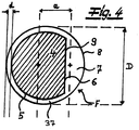
- the Fig. 4 shows bicomponent filaments with an eccentric core-sheath configuration, which are particularly preferred in the context of the invention.
- a cross section through an endless filament F with the preferred special core-sheath configuration is shown.
- the sheath 37 preferably has a constant thickness d in the filament cross section and in the exemplary embodiment over more than 50%, preferably over more than 55% of the filament circumference.
- the core 4 of the filaments F takes up more than 65% of the area of the filament cross-section of the filaments F.
- the core 4 - viewed in the filament cross section - is configured in the shape of a segment of a circle.
- this core 4 has an arcuate circumferential section 5 and a linear circumferential section 6 with respect to its circumference.
- the jacket 37 of the filaments F - viewed in the filament cross section - is designed in the shape of a segment of a circle outside the jacket area with the constant thickness d.
- This circular segment 7 of the jacket 37 has, as recommended and in the exemplary embodiment with respect to its circumference, an arcuate circumferential section 8 and a linear circumferential section 9.
- the thickness d or the mean thickness d of the jacket 37 in the range of its constant thickness is preferably 0.5% to 8%, in particular 2% to 10% of the filament diameter D.
- the thickness d of the jacket 37 may be in the range of its constant Thickness is 0.05 ⁇ m to 3 ⁇ m.
Landscapes
- Engineering & Computer Science (AREA)
- Textile Engineering (AREA)
- Nonwoven Fabrics (AREA)
Priority Applications (11)
| Application Number | Priority Date | Filing Date | Title |
|---|---|---|---|
| ES19189231T ES2911184T3 (es) | 2019-07-30 | 2019-07-30 | Dispositivo y procedimiento para producir un material no tejido |
| EP19189231.4A EP3771764B1 (fr) | 2019-07-30 | 2019-07-30 | Dispositif et procédé de fabrication d'un tissu non tissé |
| SI201930217T SI3771764T1 (sl) | 2019-07-30 | 2019-07-30 | Naprava in postopek za proizvodnjo koprenske tekstilije |
| PL19189231T PL3771764T3 (pl) | 2019-07-30 | 2019-07-30 | Urządzenie i sposób do wytwarzania włókniny |
| BR112021024827-7A BR112021024827B1 (pt) | 2019-07-30 | 2020-07-07 | Dispositivo e processo para produção de um tnt |
| IL290117A IL290117B2 (en) | 2019-07-30 | 2020-07-07 | Apparatus and method for producing non-woven fabric |
| PCT/EP2020/069133 WO2021018526A1 (fr) | 2019-07-30 | 2020-07-07 | Dispositif et procédé pour produire un tissu non-tissé |
| KR1020227006216A KR20220037493A (ko) | 2019-07-30 | 2020-07-07 | 부직포를 제조하기 위한 장치 및 방법 |
| US17/614,466 US20220234329A1 (en) | 2019-07-30 | 2020-07-07 | Method and apparatus for making a nonwoven fabric |
| CN202080054728.6A CN114174577A (zh) | 2019-07-30 | 2020-07-07 | 用于制造非织造织物的设备和方法 |
| JP2022502285A JP2022542653A (ja) | 2019-07-30 | 2020-07-07 | 不織布材料の製造のための装置および方法 |
Applications Claiming Priority (1)
| Application Number | Priority Date | Filing Date | Title |
|---|---|---|---|
| EP19189231.4A EP3771764B1 (fr) | 2019-07-30 | 2019-07-30 | Dispositif et procédé de fabrication d'un tissu non tissé |
Publications (2)
| Publication Number | Publication Date |
|---|---|
| EP3771764A1 true EP3771764A1 (fr) | 2021-02-03 |
| EP3771764B1 EP3771764B1 (fr) | 2022-02-09 |
Family
ID=67658317
Family Applications (1)
| Application Number | Title | Priority Date | Filing Date |
|---|---|---|---|
| EP19189231.4A Active EP3771764B1 (fr) | 2019-07-30 | 2019-07-30 | Dispositif et procédé de fabrication d'un tissu non tissé |
Country Status (11)
| Country | Link |
|---|---|
| US (1) | US20220234329A1 (fr) |
| EP (1) | EP3771764B1 (fr) |
| JP (1) | JP2022542653A (fr) |
| KR (1) | KR20220037493A (fr) |
| CN (1) | CN114174577A (fr) |
| BR (1) | BR112021024827B1 (fr) |
| ES (1) | ES2911184T3 (fr) |
| IL (1) | IL290117B2 (fr) |
| PL (1) | PL3771764T3 (fr) |
| SI (1) | SI3771764T1 (fr) |
| WO (1) | WO2021018526A1 (fr) |
Families Citing this family (2)
| Publication number | Priority date | Publication date | Assignee | Title |
|---|---|---|---|---|
| ES2907976T3 (es) * | 2019-07-30 | 2022-04-27 | Reifenhaeuser Masch | Dispositivo y procedimiento para producir un material no tejido de fibras rizadas |
| DE102022115205A1 (de) | 2022-06-17 | 2023-12-28 | Reifenhäuser GmbH & Co. KG Maschinenfabrik | Verfahren und Vorrichtung zur Herstellung eines Vliesstoffes |
Citations (5)
| Publication number | Priority date | Publication date | Assignee | Title |
|---|---|---|---|---|
| EP0696333A1 (fr) * | 1993-04-29 | 1996-02-14 | Kimberly-Clark Worldwide, Inc. | Non-tisse mis en forme et procede de fabrication |
| WO2002018693A2 (fr) * | 2000-08-31 | 2002-03-07 | Kimberly-Clark Worldwide, Inc. | Matiere lamellee non tissee unifiee |
| US20020090499A1 (en) * | 2000-12-22 | 2002-07-11 | Shelley Jeffrey David | Multi-layer approach to producing homofilament crimp spunbond |
| US20050020170A1 (en) * | 2003-07-25 | 2005-01-27 | Deka Ganesh Chandra | Nonwoven fabric with abrasion resistance and reduced surface fuzziness |
| WO2018064595A1 (fr) * | 2016-09-30 | 2018-04-05 | Kimberly-Clark Worldwide, Inc. | Tissus non tissés non plans et leurs procédés de fabrication |
Family Cites Families (9)
| Publication number | Priority date | Publication date | Assignee | Title |
|---|---|---|---|---|
| US5707468A (en) * | 1994-12-22 | 1998-01-13 | Kimberly-Clark Worldwide, Inc. | Compaction-free method of increasing the integrity of a nonwoven web |
| US5709735A (en) * | 1995-10-20 | 1998-01-20 | Kimberly-Clark Worldwide, Inc. | High stiffness nonwoven filter medium |
| EP1432861B2 (fr) * | 2001-09-26 | 2011-10-19 | Fiberweb Simpsonville, Inc. | Appareil et procede de production d'un toile de filaments non tisses |
| ATE381630T1 (de) * | 2002-02-28 | 2008-01-15 | Reifenhaeuser Gmbh & Co Kg | Anlage zur kontinuierlichen herstellung einer spinnvliesbahn |
| PL1726700T3 (pl) * | 2005-05-25 | 2013-08-30 | Reifenhaeuser Masch | Sposób i urządzenie do wytwarzania włókniny "spod filiery" |
| DE102005048443A1 (de) * | 2005-10-07 | 2007-04-12 | Linotec Development Gmbh | Spinnvlies-Filmlaminat |
| US9322114B2 (en) * | 2012-12-03 | 2016-04-26 | Exxonmobil Chemical Patents Inc. | Polypropylene fibers and fabrics |
| PL2907909T3 (pl) * | 2014-02-17 | 2018-01-31 | Reifenhaeuser Masch | Urządzenie do ciągłego wytwarzania wstęgi włókniny typu spunbond |
| DE102016109115A1 (de) * | 2016-05-18 | 2017-11-23 | Reifenhäuser GmbH & Co. KG Maschinenfabrik | Spinnvlies aus Endlosfilamenten |
-
2019
- 2019-07-30 PL PL19189231T patent/PL3771764T3/pl unknown
- 2019-07-30 EP EP19189231.4A patent/EP3771764B1/fr active Active
- 2019-07-30 SI SI201930217T patent/SI3771764T1/sl unknown
- 2019-07-30 ES ES19189231T patent/ES2911184T3/es active Active
-
2020
- 2020-07-07 IL IL290117A patent/IL290117B2/en unknown
- 2020-07-07 BR BR112021024827-7A patent/BR112021024827B1/pt active IP Right Grant
- 2020-07-07 CN CN202080054728.6A patent/CN114174577A/zh active Pending
- 2020-07-07 WO PCT/EP2020/069133 patent/WO2021018526A1/fr active Application Filing
- 2020-07-07 KR KR1020227006216A patent/KR20220037493A/ko unknown
- 2020-07-07 US US17/614,466 patent/US20220234329A1/en active Pending
- 2020-07-07 JP JP2022502285A patent/JP2022542653A/ja active Pending
Patent Citations (5)
| Publication number | Priority date | Publication date | Assignee | Title |
|---|---|---|---|---|
| EP0696333A1 (fr) * | 1993-04-29 | 1996-02-14 | Kimberly-Clark Worldwide, Inc. | Non-tisse mis en forme et procede de fabrication |
| WO2002018693A2 (fr) * | 2000-08-31 | 2002-03-07 | Kimberly-Clark Worldwide, Inc. | Matiere lamellee non tissee unifiee |
| US20020090499A1 (en) * | 2000-12-22 | 2002-07-11 | Shelley Jeffrey David | Multi-layer approach to producing homofilament crimp spunbond |
| US20050020170A1 (en) * | 2003-07-25 | 2005-01-27 | Deka Ganesh Chandra | Nonwoven fabric with abrasion resistance and reduced surface fuzziness |
| WO2018064595A1 (fr) * | 2016-09-30 | 2018-04-05 | Kimberly-Clark Worldwide, Inc. | Tissus non tissés non plans et leurs procédés de fabrication |
Also Published As
| Publication number | Publication date |
|---|---|
| CN114174577A (zh) | 2022-03-11 |
| EP3771764B1 (fr) | 2022-02-09 |
| BR112021024827A2 (pt) | 2022-03-22 |
| WO2021018526A1 (fr) | 2021-02-04 |
| IL290117A (en) | 2022-03-01 |
| US20220234329A1 (en) | 2022-07-28 |
| IL290117B1 (en) | 2023-07-01 |
| BR112021024827B1 (pt) | 2024-01-02 |
| KR20220037493A (ko) | 2022-03-24 |
| ES2911184T3 (es) | 2022-05-18 |
| SI3771764T1 (sl) | 2022-05-31 |
| IL290117B2 (en) | 2023-11-01 |
| PL3771764T3 (pl) | 2022-05-23 |
| JP2022542653A (ja) | 2022-10-06 |
Similar Documents
| Publication | Publication Date | Title |
|---|---|---|
| EP3088585B1 (fr) | Procédé et dispositif de production d'un non-tissé en filaments et non-tissé | |
| DE2639466C3 (de) | Verfahren und Vorrichtung zur Herstellung eines nichtgewebten Textilmaterials | |
| DE2541336C2 (de) | Verfahren zur Herstellung einer Faservliesware mit biaxialer Orientierung der Fasern und Vorrichtung zur Durchführung des Verfahrens | |
| EP3521496B1 (fr) | Stratifié non-tissé et procédé de fabrication d'un stratifié non-tissé | |
| DE19929709A1 (de) | Verfahren und Vorrichtung zur Herstellung von im Wesentlichen endlosen feinen Fäden | |
| EP3192910B1 (fr) | Procede de fabrication d'un lamine et lamine | |
| EP0598463B1 (fr) | Procédé et installation pour produire et coucher des faiseaux de filaments continus au moyen de force d'air | |
| EP1630265B1 (fr) | Appareil pour la fabrication en continu d'un voile de tissé-lié | |
| EP3771763B1 (fr) | Dispositif et procédé de fabrication d'un non-tissé de fibres bouclées | |
| EP3771764B1 (fr) | Dispositif et procédé de fabrication d'un tissu non tissé | |
| EP3771761B1 (fr) | Non-tissé obtenu par fusion-soufflage des filaments continus et dispositif de production de non-tissé obtenu par fusion-soufflage | |
| EP3771556B1 (fr) | Stratifié non-tissé et procédé de fabrication d'un stratifié non-tissé | |
| WO2004083510A1 (fr) | Procede et dispositif pour filer et deposer une nappe de fils synthetiques destines a la production de non-tisses | |
| EP3382080B1 (fr) | Procédé et dispositif de fabrication d'un non-tissé à partir de fibres | |
| DE10023391A1 (de) | Verfahren und Vorrichtung zur zugspannungsfreien Förderung von Endlosformkörpern | |
| EP3199671B1 (fr) | Dispositif destine a la fabrication de matieres non tissees | |
| DE2220575A1 (de) | Vorrichtung zur Herstellung einer nichtgewebten Textilbahn | |
| EP3771762B1 (fr) | Dispositif et pro cédé de fabrication d'un non-tissé de fibre | |
| EP2169095B1 (fr) | Installation de dépose régulière d'un voile de fibres | |
| EP4123073B1 (fr) | Procédé et dispositif de fabrication d'un non tissé à partir des fibres | |
| DE102021118909B3 (de) | Verfahren zur Herstellung eines Vliesstoffes aus Fasern | |
| EP4001488B1 (fr) | Dispositif de fabrication de tissus non tissés à partir de filaments continus | |
| DE1760483A1 (de) | Fasern | |
| DE10302079B4 (de) | Vorrichtung und Verfahren zur Herstellung von gekräuselten Spinnvliesfasern oder gekräuselten schmelzgeblasenen Vliesfilamenten aus geschmolzenem thermoplastischen Material | |
| DE1560790B2 (de) | Vorrichtung zur Herstellung von Spinnvliesen mit Hilfe von Längsdüsen |
Legal Events
| Date | Code | Title | Description |
|---|---|---|---|
| PUAI | Public reference made under article 153(3) epc to a published international application that has entered the european phase |
Free format text: ORIGINAL CODE: 0009012 |
|
| STAA | Information on the status of an ep patent application or granted ep patent |
Free format text: STATUS: REQUEST FOR EXAMINATION WAS MADE |
|
| 17P | Request for examination filed |
Effective date: 20200409 |
|
| AK | Designated contracting states |
Kind code of ref document: A1 Designated state(s): AL AT BE BG CH CY CZ DE DK EE ES FI FR GB GR HR HU IE IS IT LI LT LU LV MC MK MT NL NO PL PT RO RS SE SI SK SM TR |
|
| AX | Request for extension of the european patent |
Extension state: BA ME |
|
| STAA | Information on the status of an ep patent application or granted ep patent |
Free format text: STATUS: EXAMINATION IS IN PROGRESS |
|
| 17Q | First examination report despatched |
Effective date: 20210519 |
|
| GRAP | Despatch of communication of intention to grant a patent |
Free format text: ORIGINAL CODE: EPIDOSNIGR1 |
|
| STAA | Information on the status of an ep patent application or granted ep patent |
Free format text: STATUS: GRANT OF PATENT IS INTENDED |
|
| INTG | Intention to grant announced |
Effective date: 20210910 |
|
| GRAS | Grant fee paid |
Free format text: ORIGINAL CODE: EPIDOSNIGR3 |
|
| GRAA | (expected) grant |
Free format text: ORIGINAL CODE: 0009210 |
|
| STAA | Information on the status of an ep patent application or granted ep patent |
Free format text: STATUS: THE PATENT HAS BEEN GRANTED |
|
| AK | Designated contracting states |
Kind code of ref document: B1 Designated state(s): AL AT BE BG CH CY CZ DE DK EE ES FI FR GB GR HR HU IE IS IT LI LT LU LV MC MK MT NL NO PL PT RO RS SE SI SK SM TR |
|
| REG | Reference to a national code |
Ref country code: GB Ref legal event code: FG4D Free format text: NOT ENGLISH |
|
| REG | Reference to a national code |
Ref country code: CH Ref legal event code: EP Ref country code: AT Ref legal event code: REF Ref document number: 1467567 Country of ref document: AT Kind code of ref document: T Effective date: 20220215 |
|
| REG | Reference to a national code |
Ref country code: DE Ref legal event code: R096 Ref document number: 502019003387 Country of ref document: DE |
|
| REG | Reference to a national code |
Ref country code: IE Ref legal event code: FG4D Free format text: LANGUAGE OF EP DOCUMENT: GERMAN |
|
| REG | Reference to a national code |
Ref country code: NL Ref legal event code: FP |
|
| REG | Reference to a national code |
Ref country code: SE Ref legal event code: TRGR |
|
| REG | Reference to a national code |
Ref country code: ES Ref legal event code: FG2A Ref document number: 2911184 Country of ref document: ES Kind code of ref document: T3 Effective date: 20220518 |
|
| REG | Reference to a national code |
Ref country code: LT Ref legal event code: MG9D Ref country code: GR Ref legal event code: EP Ref document number: 20220400822 Country of ref document: GR Effective date: 20220509 |
|
| PG25 | Lapsed in a contracting state [announced via postgrant information from national office to epo] |
Ref country code: RS Free format text: LAPSE BECAUSE OF FAILURE TO SUBMIT A TRANSLATION OF THE DESCRIPTION OR TO PAY THE FEE WITHIN THE PRESCRIBED TIME-LIMIT Effective date: 20220209 Ref country code: PT Free format text: LAPSE BECAUSE OF FAILURE TO SUBMIT A TRANSLATION OF THE DESCRIPTION OR TO PAY THE FEE WITHIN THE PRESCRIBED TIME-LIMIT Effective date: 20220609 Ref country code: NO Free format text: LAPSE BECAUSE OF FAILURE TO SUBMIT A TRANSLATION OF THE DESCRIPTION OR TO PAY THE FEE WITHIN THE PRESCRIBED TIME-LIMIT Effective date: 20220509 Ref country code: LT Free format text: LAPSE BECAUSE OF FAILURE TO SUBMIT A TRANSLATION OF THE DESCRIPTION OR TO PAY THE FEE WITHIN THE PRESCRIBED TIME-LIMIT Effective date: 20220209 Ref country code: HR Free format text: LAPSE BECAUSE OF FAILURE TO SUBMIT A TRANSLATION OF THE DESCRIPTION OR TO PAY THE FEE WITHIN THE PRESCRIBED TIME-LIMIT Effective date: 20220209 Ref country code: BG Free format text: LAPSE BECAUSE OF FAILURE TO SUBMIT A TRANSLATION OF THE DESCRIPTION OR TO PAY THE FEE WITHIN THE PRESCRIBED TIME-LIMIT Effective date: 20220509 |
|
| PG25 | Lapsed in a contracting state [announced via postgrant information from national office to epo] |
Ref country code: LV Free format text: LAPSE BECAUSE OF FAILURE TO SUBMIT A TRANSLATION OF THE DESCRIPTION OR TO PAY THE FEE WITHIN THE PRESCRIBED TIME-LIMIT Effective date: 20220209 Ref country code: FI Free format text: LAPSE BECAUSE OF FAILURE TO SUBMIT A TRANSLATION OF THE DESCRIPTION OR TO PAY THE FEE WITHIN THE PRESCRIBED TIME-LIMIT Effective date: 20220209 |
|
| PG25 | Lapsed in a contracting state [announced via postgrant information from national office to epo] |
Ref country code: IS Free format text: LAPSE BECAUSE OF FAILURE TO SUBMIT A TRANSLATION OF THE DESCRIPTION OR TO PAY THE FEE WITHIN THE PRESCRIBED TIME-LIMIT Effective date: 20220609 |
|
| PG25 | Lapsed in a contracting state [announced via postgrant information from national office to epo] |
Ref country code: SM Free format text: LAPSE BECAUSE OF FAILURE TO SUBMIT A TRANSLATION OF THE DESCRIPTION OR TO PAY THE FEE WITHIN THE PRESCRIBED TIME-LIMIT Effective date: 20220209 Ref country code: SK Free format text: LAPSE BECAUSE OF FAILURE TO SUBMIT A TRANSLATION OF THE DESCRIPTION OR TO PAY THE FEE WITHIN THE PRESCRIBED TIME-LIMIT Effective date: 20220209 Ref country code: RO Free format text: LAPSE BECAUSE OF FAILURE TO SUBMIT A TRANSLATION OF THE DESCRIPTION OR TO PAY THE FEE WITHIN THE PRESCRIBED TIME-LIMIT Effective date: 20220209 Ref country code: EE Free format text: LAPSE BECAUSE OF FAILURE TO SUBMIT A TRANSLATION OF THE DESCRIPTION OR TO PAY THE FEE WITHIN THE PRESCRIBED TIME-LIMIT Effective date: 20220209 Ref country code: DK Free format text: LAPSE BECAUSE OF FAILURE TO SUBMIT A TRANSLATION OF THE DESCRIPTION OR TO PAY THE FEE WITHIN THE PRESCRIBED TIME-LIMIT Effective date: 20220209 |
|
| REG | Reference to a national code |
Ref country code: DE Ref legal event code: R097 Ref document number: 502019003387 Country of ref document: DE |
|
| PG25 | Lapsed in a contracting state [announced via postgrant information from national office to epo] |
Ref country code: AL Free format text: LAPSE BECAUSE OF FAILURE TO SUBMIT A TRANSLATION OF THE DESCRIPTION OR TO PAY THE FEE WITHIN THE PRESCRIBED TIME-LIMIT Effective date: 20220209 |
|
| PLBE | No opposition filed within time limit |
Free format text: ORIGINAL CODE: 0009261 |
|
| STAA | Information on the status of an ep patent application or granted ep patent |
Free format text: STATUS: NO OPPOSITION FILED WITHIN TIME LIMIT |
|
| 26N | No opposition filed |
Effective date: 20221110 |
|
| PG25 | Lapsed in a contracting state [announced via postgrant information from national office to epo] |
Ref country code: MC Free format text: LAPSE BECAUSE OF FAILURE TO SUBMIT A TRANSLATION OF THE DESCRIPTION OR TO PAY THE FEE WITHIN THE PRESCRIBED TIME-LIMIT Effective date: 20220209 |
|
| PG25 | Lapsed in a contracting state [announced via postgrant information from national office to epo] |
Ref country code: LU Free format text: LAPSE BECAUSE OF NON-PAYMENT OF DUE FEES Effective date: 20220730 |
|
| PG25 | Lapsed in a contracting state [announced via postgrant information from national office to epo] |
Ref country code: IE Free format text: LAPSE BECAUSE OF NON-PAYMENT OF DUE FEES Effective date: 20220730 |
|
| PGFP | Annual fee paid to national office [announced via postgrant information from national office to epo] |
Ref country code: CZ Payment date: 20230621 Year of fee payment: 5 |
|
| PGFP | Annual fee paid to national office [announced via postgrant information from national office to epo] |
Ref country code: PL Payment date: 20230623 Year of fee payment: 5 Ref country code: NL Payment date: 20230724 Year of fee payment: 5 |
|
| PGFP | Annual fee paid to national office [announced via postgrant information from national office to epo] |
Ref country code: TR Payment date: 20230726 Year of fee payment: 5 Ref country code: IT Payment date: 20230727 Year of fee payment: 5 Ref country code: GB Payment date: 20230720 Year of fee payment: 5 Ref country code: ES Payment date: 20230801 Year of fee payment: 5 Ref country code: CH Payment date: 20230801 Year of fee payment: 5 |
|
| PGFP | Annual fee paid to national office [announced via postgrant information from national office to epo] |
Ref country code: SI Payment date: 20230629 Year of fee payment: 5 Ref country code: SE Payment date: 20230721 Year of fee payment: 5 Ref country code: GR Payment date: 20230721 Year of fee payment: 5 Ref country code: FR Payment date: 20230721 Year of fee payment: 5 Ref country code: DE Payment date: 20230724 Year of fee payment: 5 Ref country code: BE Payment date: 20230720 Year of fee payment: 5 |
|
| PG25 | Lapsed in a contracting state [announced via postgrant information from national office to epo] |
Ref country code: MK Free format text: LAPSE BECAUSE OF FAILURE TO SUBMIT A TRANSLATION OF THE DESCRIPTION OR TO PAY THE FEE WITHIN THE PRESCRIBED TIME-LIMIT Effective date: 20220209 Ref country code: CY Free format text: LAPSE BECAUSE OF FAILURE TO SUBMIT A TRANSLATION OF THE DESCRIPTION OR TO PAY THE FEE WITHIN THE PRESCRIBED TIME-LIMIT Effective date: 20220209 |