EP3771762B1 - Dispositif et pro cédé de fabrication d'un non-tissé de fibre - Google Patents
Dispositif et pro cédé de fabrication d'un non-tissé de fibre Download PDFInfo
- Publication number
- EP3771762B1 EP3771762B1 EP19189208.2A EP19189208A EP3771762B1 EP 3771762 B1 EP3771762 B1 EP 3771762B1 EP 19189208 A EP19189208 A EP 19189208A EP 3771762 B1 EP3771762 B1 EP 3771762B1
- Authority
- EP
- European Patent Office
- Prior art keywords
- conveyor
- extraction area
- suction
- area
- section
- Prior art date
- Legal status (The legal status is an assumption and is not a legal conclusion. Google has not performed a legal analysis and makes no representation as to the accuracy of the status listed.)
- Active
Links
- 238000004519 manufacturing process Methods 0.000 title claims description 9
- 239000000835 fiber Substances 0.000 title description 39
- 238000005192 partition Methods 0.000 claims description 109
- 238000000151 deposition Methods 0.000 claims description 84
- 238000000605 extraction Methods 0.000 claims description 71
- 239000004745 nonwoven fabric Substances 0.000 claims description 44
- 238000000034 method Methods 0.000 claims description 42
- 238000007596 consolidation process Methods 0.000 claims description 35
- 238000009987 spinning Methods 0.000 claims description 35
- 230000008569 process Effects 0.000 claims description 30
- 238000011144 upstream manufacturing Methods 0.000 claims description 29
- 230000007704 transition Effects 0.000 claims description 28
- 238000001816 cooling Methods 0.000 claims description 21
- 230000007423 decrease Effects 0.000 claims description 15
- 239000012815 thermoplastic material Substances 0.000 claims description 6
- 230000008021 deposition Effects 0.000 claims description 3
- 239000000463 material Substances 0.000 claims description 2
- 238000003860 storage Methods 0.000 description 47
- 239000000306 component Substances 0.000 description 20
- -1 polyethylene Polymers 0.000 description 10
- 230000007547 defect Effects 0.000 description 8
- 230000000694 effects Effects 0.000 description 7
- 229920000098 polyolefin Polymers 0.000 description 7
- 229920000728 polyester Polymers 0.000 description 6
- 239000004698 Polyethylene Substances 0.000 description 5
- 239000004743 Polypropylene Substances 0.000 description 5
- 238000005054 agglomeration Methods 0.000 description 4
- 230000002776 aggregation Effects 0.000 description 4
- 229920000573 polyethylene Polymers 0.000 description 4
- 229920001155 polypropylene Polymers 0.000 description 4
- 229920001634 Copolyester Polymers 0.000 description 3
- 238000005299 abrasion Methods 0.000 description 3
- 239000000178 monomer Substances 0.000 description 3
- 229920000747 poly(lactic acid) Polymers 0.000 description 3
- 229920001707 polybutylene terephthalate Polymers 0.000 description 3
- 229920000139 polyethylene terephthalate Polymers 0.000 description 3
- 239000005020 polyethylene terephthalate Substances 0.000 description 3
- 230000008901 benefit Effects 0.000 description 2
- 229920001577 copolymer Polymers 0.000 description 2
- 239000007789 gas Substances 0.000 description 2
- 230000006872 improvement Effects 0.000 description 2
- 238000002844 melting Methods 0.000 description 2
- 230000008018 melting Effects 0.000 description 2
- 239000000203 mixture Substances 0.000 description 2
- 229920003023 plastic Polymers 0.000 description 2
- 239000004033 plastic Substances 0.000 description 2
- 229920000642 polymer Polymers 0.000 description 2
- 230000009467 reduction Effects 0.000 description 2
- 238000000638 solvent extraction Methods 0.000 description 2
- 239000008358 core component Substances 0.000 description 1
- 238000000354 decomposition reaction Methods 0.000 description 1
- 229920006240 drawn fiber Polymers 0.000 description 1
- 230000002452 interceptive effect Effects 0.000 description 1
- 239000000126 substance Substances 0.000 description 1
Images


Classifications
-
- D—TEXTILES; PAPER
- D04—BRAIDING; LACE-MAKING; KNITTING; TRIMMINGS; NON-WOVEN FABRICS
- D04H—MAKING TEXTILE FABRICS, e.g. FROM FIBRES OR FILAMENTARY MATERIAL; FABRICS MADE BY SUCH PROCESSES OR APPARATUS, e.g. FELTS, NON-WOVEN FABRICS; COTTON-WOOL; WADDING ; NON-WOVEN FABRICS FROM STAPLE FIBRES, FILAMENTS OR YARNS, BONDED WITH AT LEAST ONE WEB-LIKE MATERIAL DURING THEIR CONSOLIDATION
- D04H3/00—Non-woven fabrics formed wholly or mainly of yarns or like filamentary material of substantial length
- D04H3/02—Non-woven fabrics formed wholly or mainly of yarns or like filamentary material of substantial length characterised by the method of forming fleeces or layers, e.g. reorientation of yarns or filaments
-
- D—TEXTILES; PAPER
- D04—BRAIDING; LACE-MAKING; KNITTING; TRIMMINGS; NON-WOVEN FABRICS
- D04H—MAKING TEXTILE FABRICS, e.g. FROM FIBRES OR FILAMENTARY MATERIAL; FABRICS MADE BY SUCH PROCESSES OR APPARATUS, e.g. FELTS, NON-WOVEN FABRICS; COTTON-WOOL; WADDING ; NON-WOVEN FABRICS FROM STAPLE FIBRES, FILAMENTS OR YARNS, BONDED WITH AT LEAST ONE WEB-LIKE MATERIAL DURING THEIR CONSOLIDATION
- D04H1/00—Non-woven fabrics formed wholly or mainly of staple fibres or like relatively short fibres
-
- D—TEXTILES; PAPER
- D04—BRAIDING; LACE-MAKING; KNITTING; TRIMMINGS; NON-WOVEN FABRICS
- D04H—MAKING TEXTILE FABRICS, e.g. FROM FIBRES OR FILAMENTARY MATERIAL; FABRICS MADE BY SUCH PROCESSES OR APPARATUS, e.g. FELTS, NON-WOVEN FABRICS; COTTON-WOOL; WADDING ; NON-WOVEN FABRICS FROM STAPLE FIBRES, FILAMENTS OR YARNS, BONDED WITH AT LEAST ONE WEB-LIKE MATERIAL DURING THEIR CONSOLIDATION
- D04H3/00—Non-woven fabrics formed wholly or mainly of yarns or like filamentary material of substantial length
- D04H3/002—Inorganic yarns or filaments
-
- D—TEXTILES; PAPER
- D01—NATURAL OR MAN-MADE THREADS OR FIBRES; SPINNING
- D01D—MECHANICAL METHODS OR APPARATUS IN THE MANUFACTURE OF ARTIFICIAL FILAMENTS, THREADS, FIBRES, BRISTLES OR RIBBONS
- D01D5/00—Formation of filaments, threads, or the like
- D01D5/08—Melt spinning methods
- D01D5/088—Cooling filaments, threads or the like, leaving the spinnerettes
-
- D—TEXTILES; PAPER
- D01—NATURAL OR MAN-MADE THREADS OR FIBRES; SPINNING
- D01D—MECHANICAL METHODS OR APPARATUS IN THE MANUFACTURE OF ARTIFICIAL FILAMENTS, THREADS, FIBRES, BRISTLES OR RIBBONS
- D01D5/00—Formation of filaments, threads, or the like
- D01D5/08—Melt spinning methods
- D01D5/098—Melt spinning methods with simultaneous stretching
- D01D5/0985—Melt spinning methods with simultaneous stretching by means of a flowing gas (e.g. melt-blowing)
-
- D—TEXTILES; PAPER
- D01—NATURAL OR MAN-MADE THREADS OR FIBRES; SPINNING
- D01D—MECHANICAL METHODS OR APPARATUS IN THE MANUFACTURE OF ARTIFICIAL FILAMENTS, THREADS, FIBRES, BRISTLES OR RIBBONS
- D01D5/00—Formation of filaments, threads, or the like
- D01D5/28—Formation of filaments, threads, or the like while mixing different spinning solutions or melts during the spinning operation; Spinnerette packs therefor
- D01D5/30—Conjugate filaments; Spinnerette packs therefor
- D01D5/34—Core-skin structure; Spinnerette packs therefor
-
- D—TEXTILES; PAPER
- D01—NATURAL OR MAN-MADE THREADS OR FIBRES; SPINNING
- D01G—PRELIMINARY TREATMENT OF FIBRES, e.g. FOR SPINNING
- D01G25/00—Lap-forming devices not integral with machines specified above
-
- D—TEXTILES; PAPER
- D04—BRAIDING; LACE-MAKING; KNITTING; TRIMMINGS; NON-WOVEN FABRICS
- D04H—MAKING TEXTILE FABRICS, e.g. FROM FIBRES OR FILAMENTARY MATERIAL; FABRICS MADE BY SUCH PROCESSES OR APPARATUS, e.g. FELTS, NON-WOVEN FABRICS; COTTON-WOOL; WADDING ; NON-WOVEN FABRICS FROM STAPLE FIBRES, FILAMENTS OR YARNS, BONDED WITH AT LEAST ONE WEB-LIKE MATERIAL DURING THEIR CONSOLIDATION
- D04H1/00—Non-woven fabrics formed wholly or mainly of staple fibres or like relatively short fibres
- D04H1/40—Non-woven fabrics formed wholly or mainly of staple fibres or like relatively short fibres from fleeces or layers composed of fibres without existing or potential cohesive properties
- D04H1/42—Non-woven fabrics formed wholly or mainly of staple fibres or like relatively short fibres from fleeces or layers composed of fibres without existing or potential cohesive properties characterised by the use of certain kinds of fibres insofar as this use has no preponderant influence on the consolidation of the fleece
- D04H1/4282—Addition polymers
- D04H1/4291—Olefin series
-
- D—TEXTILES; PAPER
- D04—BRAIDING; LACE-MAKING; KNITTING; TRIMMINGS; NON-WOVEN FABRICS
- D04H—MAKING TEXTILE FABRICS, e.g. FROM FIBRES OR FILAMENTARY MATERIAL; FABRICS MADE BY SUCH PROCESSES OR APPARATUS, e.g. FELTS, NON-WOVEN FABRICS; COTTON-WOOL; WADDING ; NON-WOVEN FABRICS FROM STAPLE FIBRES, FILAMENTS OR YARNS, BONDED WITH AT LEAST ONE WEB-LIKE MATERIAL DURING THEIR CONSOLIDATION
- D04H1/00—Non-woven fabrics formed wholly or mainly of staple fibres or like relatively short fibres
- D04H1/40—Non-woven fabrics formed wholly or mainly of staple fibres or like relatively short fibres from fleeces or layers composed of fibres without existing or potential cohesive properties
- D04H1/42—Non-woven fabrics formed wholly or mainly of staple fibres or like relatively short fibres from fleeces or layers composed of fibres without existing or potential cohesive properties characterised by the use of certain kinds of fibres insofar as this use has no preponderant influence on the consolidation of the fleece
- D04H1/4326—Condensation or reaction polymers
- D04H1/435—Polyesters
-
- D—TEXTILES; PAPER
- D04—BRAIDING; LACE-MAKING; KNITTING; TRIMMINGS; NON-WOVEN FABRICS
- D04H—MAKING TEXTILE FABRICS, e.g. FROM FIBRES OR FILAMENTARY MATERIAL; FABRICS MADE BY SUCH PROCESSES OR APPARATUS, e.g. FELTS, NON-WOVEN FABRICS; COTTON-WOOL; WADDING ; NON-WOVEN FABRICS FROM STAPLE FIBRES, FILAMENTS OR YARNS, BONDED WITH AT LEAST ONE WEB-LIKE MATERIAL DURING THEIR CONSOLIDATION
- D04H3/00—Non-woven fabrics formed wholly or mainly of yarns or like filamentary material of substantial length
- D04H3/005—Synthetic yarns or filaments
- D04H3/007—Addition polymers
-
- D—TEXTILES; PAPER
- D04—BRAIDING; LACE-MAKING; KNITTING; TRIMMINGS; NON-WOVEN FABRICS
- D04H—MAKING TEXTILE FABRICS, e.g. FROM FIBRES OR FILAMENTARY MATERIAL; FABRICS MADE BY SUCH PROCESSES OR APPARATUS, e.g. FELTS, NON-WOVEN FABRICS; COTTON-WOOL; WADDING ; NON-WOVEN FABRICS FROM STAPLE FIBRES, FILAMENTS OR YARNS, BONDED WITH AT LEAST ONE WEB-LIKE MATERIAL DURING THEIR CONSOLIDATION
- D04H3/00—Non-woven fabrics formed wholly or mainly of yarns or like filamentary material of substantial length
- D04H3/005—Synthetic yarns or filaments
- D04H3/009—Condensation or reaction polymers
- D04H3/011—Polyesters
-
- D—TEXTILES; PAPER
- D04—BRAIDING; LACE-MAKING; KNITTING; TRIMMINGS; NON-WOVEN FABRICS
- D04H—MAKING TEXTILE FABRICS, e.g. FROM FIBRES OR FILAMENTARY MATERIAL; FABRICS MADE BY SUCH PROCESSES OR APPARATUS, e.g. FELTS, NON-WOVEN FABRICS; COTTON-WOOL; WADDING ; NON-WOVEN FABRICS FROM STAPLE FIBRES, FILAMENTS OR YARNS, BONDED WITH AT LEAST ONE WEB-LIKE MATERIAL DURING THEIR CONSOLIDATION
- D04H3/00—Non-woven fabrics formed wholly or mainly of yarns or like filamentary material of substantial length
- D04H3/08—Non-woven fabrics formed wholly or mainly of yarns or like filamentary material of substantial length characterised by the method of strengthening or consolidating
- D04H3/14—Non-woven fabrics formed wholly or mainly of yarns or like filamentary material of substantial length characterised by the method of strengthening or consolidating with bonds between thermoplastic yarns or filaments produced by welding
-
- D—TEXTILES; PAPER
- D04—BRAIDING; LACE-MAKING; KNITTING; TRIMMINGS; NON-WOVEN FABRICS
- D04H—MAKING TEXTILE FABRICS, e.g. FROM FIBRES OR FILAMENTARY MATERIAL; FABRICS MADE BY SUCH PROCESSES OR APPARATUS, e.g. FELTS, NON-WOVEN FABRICS; COTTON-WOOL; WADDING ; NON-WOVEN FABRICS FROM STAPLE FIBRES, FILAMENTS OR YARNS, BONDED WITH AT LEAST ONE WEB-LIKE MATERIAL DURING THEIR CONSOLIDATION
- D04H3/00—Non-woven fabrics formed wholly or mainly of yarns or like filamentary material of substantial length
- D04H3/08—Non-woven fabrics formed wholly or mainly of yarns or like filamentary material of substantial length characterised by the method of strengthening or consolidating
- D04H3/16—Non-woven fabrics formed wholly or mainly of yarns or like filamentary material of substantial length characterised by the method of strengthening or consolidating with bonds between thermoplastic filaments produced in association with filament formation, e.g. immediately following extrusion
-
- D—TEXTILES; PAPER
- D04—BRAIDING; LACE-MAKING; KNITTING; TRIMMINGS; NON-WOVEN FABRICS
- D04H—MAKING TEXTILE FABRICS, e.g. FROM FIBRES OR FILAMENTARY MATERIAL; FABRICS MADE BY SUCH PROCESSES OR APPARATUS, e.g. FELTS, NON-WOVEN FABRICS; COTTON-WOOL; WADDING ; NON-WOVEN FABRICS FROM STAPLE FIBRES, FILAMENTS OR YARNS, BONDED WITH AT LEAST ONE WEB-LIKE MATERIAL DURING THEIR CONSOLIDATION
- D04H3/00—Non-woven fabrics formed wholly or mainly of yarns or like filamentary material of substantial length
- D04H3/08—Non-woven fabrics formed wholly or mainly of yarns or like filamentary material of substantial length characterised by the method of strengthening or consolidating
- D04H3/10—Non-woven fabrics formed wholly or mainly of yarns or like filamentary material of substantial length characterised by the method of strengthening or consolidating with bonds between yarns or filaments made mechanically
- D04H3/11—Non-woven fabrics formed wholly or mainly of yarns or like filamentary material of substantial length characterised by the method of strengthening or consolidating with bonds between yarns or filaments made mechanically by fluid jet
-
- D—TEXTILES; PAPER
- D10—INDEXING SCHEME ASSOCIATED WITH SUBLASSES OF SECTION D, RELATING TO TEXTILES
- D10B—INDEXING SCHEME ASSOCIATED WITH SUBLASSES OF SECTION D, RELATING TO TEXTILES
- D10B2321/00—Fibres made from polymers obtained by reactions only involving carbon-to-carbon unsaturated bonds
- D10B2321/02—Fibres made from polymers obtained by reactions only involving carbon-to-carbon unsaturated bonds polyolefins
-
- D—TEXTILES; PAPER
- D10—INDEXING SCHEME ASSOCIATED WITH SUBLASSES OF SECTION D, RELATING TO TEXTILES
- D10B—INDEXING SCHEME ASSOCIATED WITH SUBLASSES OF SECTION D, RELATING TO TEXTILES
- D10B2331/00—Fibres made from polymers obtained otherwise than by reactions only involving carbon-to-carbon unsaturated bonds, e.g. polycondensation products
- D10B2331/04—Fibres made from polymers obtained otherwise than by reactions only involving carbon-to-carbon unsaturated bonds, e.g. polycondensation products polyesters, e.g. polyethylene terephthalate [PET]
Definitions
- the invention relates to a device for producing a nonwoven fabric from fibers, in particular from fibers made of thermoplastic material, at least one spinning device for spinning the fibers and an air-permeable depositing conveyor - in particular a depositing screen belt - being provided for depositing the fibers on the nonwoven web or on the nonwoven wherein at least one suction device is present with which air or process air can be sucked in through the deposit conveyor in a main suction area in the deposit area of the fibers and the main suction area below the deposit conveyor in an inlet area of the deposit conveyor and in an outlet area of the deposit conveyor are each delimited by a suction partition.
- the invention also relates to a corresponding method for producing such a nonwoven fabric from fibers.
- the fibers forming the nonwoven are continuous filaments. Endless filaments differ from staple fibers because of their quasi-endless length. B. 10 mm to 60 mm.
- the nonwoven fabric produced according to the invention is preferably composed of such continuous filaments and particularly preferably the nonwoven fabric produced with the device according to the invention or with the method according to the invention is a spunbond nonwoven fabric.
- Nonwovens with a large thickness and a high softness are required.
- a high thickness of the nonwoven fabric is usually achieved if crimped or crimped filaments are used.
- the provision of a high thickness and a high softness is generally associated with a relatively low strength of the nonwoven fabric. This applies to both the tensile strength in the machine direction (MD) and the abrasion resistance of the fleece surface.
- EP 1 079 012 A1 a device for producing a nonwoven fabric from fibers is known, this device having a spinning device and a depositing screen belt for depositing the fibers. A suction area or a main suction area for extracting process air is provided below the depositing screen belt. This main suction area is limited by suction partitions. This device has basically proven itself. Nevertheless, there is room for improvement.
- EP 1 340 842 A1 a method for producing a nonwoven fabric from fibers is known.
- the fibers are deposited on an air-permeable filing screen belt.
- a main suction area which is delimited by suction partitions, is also provided under the depositing screen belt.
- the invention is based on the technical problem of specifying a device for producing a nonwoven fabric from fibers, with which a nonwoven fabric of high thickness and high softness can be produced, but which is nonetheless also characterized by a satisfactory strength or abrasion resistance and above all largely is defect-free and, in particular, free from agglomerations.
- the invention is also based on the technical problem of specifying a corresponding method for producing such a nonwoven fabric.
- Vertical distance A means in particular a distance A which is measured along a vertical which runs through the conveyor-side end of the suction partition and is oriented perpendicular to the storage conveyor surface.
- the geometric parameters and geometric relationships specified here and below relate in particular to the device in a state without air admission, ie. H. in particular without air or process air extraction and without hot air exposure.
- the device according to the invention is preferably designed in such a way that the geometric parameters and relationships are applicable or are at least largely applicable even in the air-loaded state.
- the suction partitions or the partitions between the suction areas and the spoiler components are designed according to fluidic aspects, since the components also have flow-directing functions.
- the vertical distance A is 20 mm to 160 mm, preferably 20 mm to 150 mm, more preferably 25 mm to 150 mm and in particular 30 mm to 150 mm.
- at least one, in particular a suction partition, at its end on the conveyor side comprises a partition section which is angled from the rest of the suction partition and is designed as a spoiler section. The end on the conveyor side has this spoiler section or one with the shortest one vertical distance to the storage conveyor arranged part of this spoiler section the vertical distance A to the storage conveyor.
- the spoiler section or the angled end section of the suction partition preferably includes an angle ⁇ with a vertical V oriented perpendicular to the deposit conveyor or to the deposit conveyor surface F or with the vertical center plane M of the device.
- This angle ⁇ is expediently smaller than 90 ° and preferably smaller than 85 °.
- the spoiler section is proven to be designed as an obliquely angled spoiler section with a linear or essentially linear cross section.
- At least one, in particular a suction partition, at its conveyor-side end comprises a spoiler section in the form of an angle element with two spoiler components arranged at an angle to one another and the conveyor-side end of this spoiler section or a part of this spoiler section arranged with the shortest vertical distance to the storage conveyor has the vertical distance A to the delivery conveyor.
- the spoiler section or the angular element has a spoiler component which is oriented transversely, in particular perpendicularly or essentially perpendicularly to the depositing conveyor surface F.
- the spoiler section or the angle element has a spoiler component which is oriented parallel or essentially parallel to the depositing conveyor surface F.
- the two spoiler components are expediently connected to one another directly to form the angle element.
- the kink or bend point of the spoiler section and / or the connection point of the parallel spoiler component of the spoiler section has a vertical distance from the depositing conveyor or from the depositing screen belt of 20 mm to 200 mm, in particular from 30 mm to 190 mm.
- the maximum suction of air or process air takes place in the main suction area delimited by two suction partitions below the main storage area of the fibers. If air or process air is sucked through the delivery conveyor in further suction areas of the device according to the invention, in this preferred embodiment the air or process air sucked in the main suction area has the highest suction speed v H. It will be explained further below that further suction areas can be connected upstream and / or downstream of the main suction area.
- Suction speeds of air or process air with regard to the suction through the storage conveyor or through the storage screen are measured within the scope of the invention in particular directly above the storage conveyor or the storage screen, expediently at a distance of 0 mm to 5 mm from the storage conveyor or the storage screen .
- a suction area delimited by two suction partition walls under the main storage area for the fibers is known in principle from the prior art.
- the ends of these two suction partitions on the conveyor side are also more or less curved in some devices known from the prior art.
- the conveyor-side ends of these suction partitions extend to the depositing conveyor or to the depositing screen belt and only a very small or no distance is formed between the conveyor-side ends of the suction partitions and the depositing conveyor or the depositing screen belt.
- the device according to the invention already differs significantly from these known devices in that according to the invention a relatively large vertical distance A is maintained between the conveyor-side end of at least one suction partition and the deposit conveyor or the deposit screen belt.
- a preferred embodiment which is of particular importance in the context of the invention, is characterized in that only one suction partition of the main suction area maintains the vertical distance A from the delivery conveyor and preferably has the spoiler section at its end on the conveyor side or in its area on the conveyor side. It is recommended that this suction partition is the suction partition on the outlet side - in relation to the conveying direction of the depositing conveyor. With the aid of this embodiment, the technical problem according to the invention can be solved particularly effectively.
- the spoiler section angled from the rest of the suction partition is linear or essentially linear in cross section and the surface of this spoiler section is designed as a plane or as an essentially flat surface.
- this preferred embodiment differs from the configuration of the conveyor-side ends of suction partition walls known from the prior art, which are curved or continuously curved in their conveyor-side area.
- the angled spoiler section is angled by an angle ⁇ with respect to a vertical oriented perpendicular to the depositing conveyor surface F or with respect to a vertical center plane M of the device.
- this angle ⁇ is greater than 10 °, preferably greater than 15 °, preferably greater than 20 ° and very preferably greater than 25 °. According to a recommended embodiment of the invention, the angle ⁇ is greater than 30 °. Another preferred embodiment of the invention is distinguished characterized in that the angle ⁇ is greater than 35 ° and in particular is greater than 40 °. - It is within the scope of the invention that the angled spoiler section is more angled with respect to the vertical V oriented perpendicular to the depositing conveyor surface F or with respect to the vertical center plane M of the device than a partitioning wall section on the depositing conveyor side of the further or opposite suction partition of the main suction area.
- the spoiler section according to the invention is angled by at least 5 °, preferably at least 10 ° and preferably at least 15 ° more than the partition wall section of the further or opposite suction partition of the main suction area.
- the angled spoiler section in its projection on the storage conveyor surface F has a greater length L than the corresponding projection of a storage conveyor-side, angled or bent partition section of the further or opposite suction partition of the main suction area.
- the length L of the projection of the angled spoiler section onto the storage conveyor surface F is preferably 30 mm to 200 mm, preferably 35 mm to 180 mm and particularly preferably 40 mm to 150 mm. According to one embodiment of the invention, the length L is 50 mm to 150 mm.
- One embodiment of the invention is characterized in that the length L is greater than the distance A or equal to the distance A from the depositing conveyor.
- the vertical height h of the angled spoiler section is expediently 5 mm to 300 mm, preferably 10 mm to 150 mm and in particular 15 mm to 100 mm, in particular in the projection onto the central plane M of the device.
- the spoiler section maintains a larger vertical distance A to the storage conveyor with respect to its conveyor-side end than the conveyor-side end of the storage-conveyor-side partition wall section of the further or opposite suction partition.
- the distance A of the conveyor-side end of the spoiler section is at least 0.8 times, in particular at least 1.5 times and preferably at least 2 times as large as the corresponding distance A of the conveyor-side end of the storage conveyor-side partition section of the further or opposite suction partition of the Main suction area.
- the spoiler section extends over at least 80%, preferably over at least 85%, preferably over at least 90% and very preferably over at least 95% of the width of the depositing conveyor or the depositing screen belt transversely or perpendicular to the machine direction ( MD) extends.
- Machine direction (MD) means here and below the conveying direction of the deposit conveyor or the conveying direction of the deposited nonwoven web.
- the spoiler section is oriented or angled to the side of the associated suction partition wall facing away from the center or from the center plane M of the main suction area. In this embodiment, the spoiler section is thus aligned or angled in the conveying direction of the deposit conveyor. According to another embodiment of the invention, the spoiler section is oriented or angled towards the center or the center plane M of the main suction area. In this last-mentioned embodiment, the spoiler section is thus aligned or angled against the conveying direction of the depositing conveyor.
- the spoiler section according to the invention can advantageously be used in a two-bar system or in a multi-bar system with two or more spinning devices or spinning bars for spinning fibers.
- a particularly preferred embodiment of the invention is characterized in that at least two spinning devices or spinning beams are provided for spinning the fibers, each spinning device or each spinning beam being assigned a main suction area in which air or process air passes through the depositing conveyor or through the depositing screen belt can be suctioned, each of these main suction areas being delimited by two suction partitions, wherein at least one suction partition of each main suction area has a spoiler section, a first spoiler section of a first main suction area with respect to the conveying direction of the storage conveyor - preferably a spoiler section connected to the outlet side suction partition of this first main suction area - facing away from the center or the center plane M of this first main suction area Side of the connected suction partition is aligned or angled and wherein a second spoiler section of a second main suction area with respect to the conveying direction of the depositing conveyor - preferably a spoiler section connected to the suction partition on the outlet side of this second main suction area - is aligned or angled
- the maximum suction takes place at the highest suction speed v H.
- the is assigned to the first spinning beam in the conveying direction Spoiler section aligned or angled in the conveying direction of the storage conveyor, while the spoiler section assigned to the second spinning beam in the conveying direction is aligned or angled against the conveying direction of the storage conveyor.
- the fiber deposits or nonwoven webs produced by the at least two spinning beams are deposited on the same deposit conveyor or on the same deposit screen belt.
- the preferred embodiments and configurations explained above for the spoiler section preferably apply to the at least two spoiler sections of the two-bar system or the multi-bar system.
- a recommended embodiment which is of particular importance in the context of the invention, is characterized in that the device according to the invention is set up as a spunbond device for the production of spunbond nonwovens from continuous filaments.
- this system has at least two spunbond device components according to the invention or at least two spunbond device components connected in series.
- a device according to the invention is particularly preferably set up as a spunbond device for producing spunbond nonwovens from crimped continuous filaments. It is within the scope of the invention that the spunbond device is used to produce multicomponent filaments or bicomponent filaments which expediently have an eccentric core-sheath configuration or a side-by-side configuration.
- the device or spunbond device according to the invention has proven particularly useful for the production of crimped continuous filaments with an eccentric core-sheath configuration. Preferred embodiments for this are explained in more detail below.
- the device according to the invention or a spunbond device component has at least one cooling device downstream of the spinning device and at least one stretching device downstream of the cooling device. At least one diffuser is preferably provided downstream of the stretching device.
- a particularly preferred embodiment of the invention is characterized in that the unit from the cooling device and the stretching device is designed as a closed unit and that apart from the supply of cooling air in the cooling device, no further air is supplied from the outside into this unit.
- the fibers or continuous filaments leaving the diffuser or the last diffuser in the flow direction of the filaments are deposited on the deposit conveyor or on the deposit belt.
- a well-proven embodiment of the invention is characterized in that a diffuser arranged directly above the depositing conveyor or above the depositing screen belt has two opposite diffuser walls, two lower diverging diffuser wall sections being provided.
- the two lower diverging diffuser wall sections of the diffuser are preferably arranged asymmetrically with respect to the central plane M of the diffuser. It is recommended here that the diffuser wall section on the inlet side with respect to the depositing conveyor encloses a smaller angle ⁇ with the center plane M of the diffuser than the diffuser wall section on the outlet side.
- the angle ⁇ - which the inlet-side diffuser wall section encloses with the central plane M - is at least 1 ° less than the corresponding angle which the outlet-side diffuser wall section encloses with the central plane M.
- the asymmetrical configuration of the diffuser with respect to the center plane M has proven itself with regard to the solution of the Technical problem according to the invention particularly proven. It is within the scope of the invention that the ends of the diverging diffuser wall sections on the storage conveyor side have a different distance e from the center plane M of the device.
- the distance e 1 of the conveyor-side end of the inlet-side diffuser section is less than the distance e 2 of the conveyor-side end of the outlet-side diffuser wall section from the center plane M of the device.
- the ratio of the distances e 1 : e 2 is expediently 0.6 to 0.95, preferably 0.65 to 0.9 and in particular 0.7 to 0.9.
- the distance A to the storage conveyor is 10% to 200% of the sum of the distances e 1 and e 2 (e 1 + e 2 ).
- a preferred embodiment of the invention is characterized in that the ends of the diverging diffuser wall sections on the storage conveyor side have a different vertical distance from the storage conveyor or from the storage screen belt.
- the conveyor-side end of the inlet-side diffuser section expediently has a smaller distance from the depositing conveyor or from the depositing screen belt than the conveyor-side end of the outlet-side diffuser section.
- the distance between the conveyor-side end of the inlet-side diffuser section is 20% to 60%, in particular 20% to 40% of the distance between the conveyor-side end of the outlet-side diffuser section and the depositing conveyor.
- the distances e 1 and e 2 are expediently measured horizontally or parallel to the depositing conveyor or to the depositing screen belt.
- the aforementioned embodiment is particularly suitable for the diffuser of the second beam.
- a recommended embodiment of the invention is characterized in that the diffuser arranged directly above the discharge conveyor or above the discharge screen belt has two opposite diffuser walls, with at least two opposite secondary air inlet gaps being provided at the inflow end of the diffuser, which are each arranged on one of the two opposite diffuser walls .
- the inflowing end of the diffuser means the end of the diffuser into which the drawn fibers or filaments enter.
- a lower secondary air volume flow can preferably be introduced through the secondary air inlet gap on the inlet side with respect to the conveying direction of the deposit conveyor than through the secondary air inlet gap on the outlet side.
- the inlet-side secondary air inlet gap is designed to be narrower in the machine direction (MD) than the outlet-side secondary air inlet gap.
- the width of the inlet-side secondary air inlet gap and / or the width of the outlet-side secondary air inlet gap can be adjusted. It is recommended that the secondary air volume flow of the inlet-side secondary air inlet gap is at least 5%, preferably at least 10% and in particular at least 15% less than the secondary air volume flow through the outlet-side secondary air inlet gap.
- the embodiment with the different secondary air volume flows at the inlet-side secondary air inlet gap and the outlet-side secondary air inlet gap has proven particularly useful in terms of solving the technical problem according to the invention.
- the main suction area of the device or spunbond device according to the invention is followed by a second suction area in the conveying direction of the deposit conveyor or the depositing screen belt, in which air or process air flows through the deposit conveyor or is sucked through the filing screen.
- the suction speed v 2 of the process air through the storage conveyor or through the storage screen belt in this second suction area is preferably lower than the suction speed v H in the main suction area.
- the main suction area of a spinning beam in addition to the mentioned second suction area, is followed by further suction areas in the conveying direction of the depositing conveyor.
- a preferred embodiment of the invention is characterized in that the suction speed of the air or process air through the delivery conveyor or through the depositing screen belt from the main suction area to the other suction areas decreases in the conveying direction, so that the main suction area has the highest suction speed v H and the second suction area has the second highest suction speed v 2 and the further suction area adjoining the second suction area has a lower suction speed than the suction speed v 2 of the second suction area.
- the main suction area is preceded by an upstream suction area with respect to the conveying direction of the depositing conveyor, in which air or process air is sucked through the depositing conveyor or through the depositing screen belt.
- the suction speed vv of the process air through the delivery conveyor or through the depositing screen belt in this upstream suction area is preferably lower than the suction speed v H in the main suction area.
- the suction speed vv is expediently greater than the suction speed v 2 in the second suction area.
- Such an upstream suction area is provided in particular when the following main suction area is assigned to a spinning beam in a two-beam system or in a multi-beam system at least one first spin beam follows.
- a spoiler section connected to the suction partition on the outlet side is expediently angled towards the center or to the center plane M of the main suction area.
- this spoiler section can also be aligned or angled in the conveying direction of the deposit conveyor.
- a spoiler section connected to the outlet-side suction partition of the first main suction area of the first spinning beam is aligned or angled towards the side of the connected suction partition facing away from the center of this first main suction area and thus in the conveying direction of the storage conveyor .
- the transition area is expediently a maximum of 40 cm, in particular a maximum of 35 cm and preferably a maximum of 30 cm long.
- the above-described decrease in suction speed or increase in suction speed takes place more or less abruptly.
- a transition area of at least 10 cm is created for the continuous transition of the suction speeds.
- a particularly recommended embodiment of the invention is characterized in that at least one, in particular a pre-consolidation device for the pre-consolidation of the nonwoven fabric is arranged above the second suction region - downstream of the main suction region.
- This pre-consolidation device is expediently a hot air pre-consolidation device and preferably a hot air knife.
- a hot air oven could also be used here as a hot air pre-consolidation device.
- pre-consolidation is also possible with compacting rollers and / or with a calender.
- a proven embodiment of the invention is characterized in that the distance B between the center plane M of the device or of the diffuser and the pre-consolidation device is 100 mm to 1,000 mm, in particular 110 mm to 600 mm and preferably 120 mm to 550 mm.
- the distance B is measured in particular between the mentioned center plane M and the first component or structural component of the preconsolidation device following in the conveying direction.
- the invention also teaches a method for producing a nonwoven fabric from fibers, in particular from fibers made of thermoplastic material, the fibers being spun and deposited on an air-permeable storage conveyor, in particular on an air-permeable storage screen belt for the nonwoven web or the nonwoven fabric
- a main suction area air or process air is sucked from below through the deposit conveyor or through the depositing screen belt, the main suction area being limited by two suction partitions arranged one behind the other in the machine direction (MD), wherein a suction area is provided upstream of the main suction area or the inlet-side suction partition with respect to the conveying direction of the depositing conveyor and / or wherein a second suction area is provided downstream of the main suction area or the outlet-side suction partition, wherein in the upstream suction area and / or in the downstream, second suction area, air is sucked through the deposit conveyor or through the deposit belt at a lower suction speed
- MD machine direction
- the suction speed expediently decreases from the suction speed v H in the main suction area to the suction speed v 2 in the downstream second suction area continuously and steadily in a transition area of at least 10 cm, in particular of at least 14 cm, preferably of at least 16 cm and preferably of at least 18 cm in length .
- the length of the transition area is preferably a maximum of 40 cm and in particular a maximum of 30 cm.
- the suction speed increases from the suction speed vv in the upstream suction area to the suction speed v H in the main suction area continuously steadily in a transition area of at least 10 cm, in particular of at least 14 cm, preferably of at least 16 cm and preferably of at least 18 cm in length.
- the transition area is expediently a maximum of 40 cm and preferably a maximum of 30 cm.
- a spunbond nonwoven fabric is produced from continuous filaments and in particular from crimped continuous filaments.
- the continuous filaments are expediently bicomponent filaments or multicomponent filaments, specifically preferably bicomponent filaments or multicomponent filaments with an eccentric core-sheath configuration.
- Bicomponent filaments or multicomponent filaments with an eccentric core-sheath configuration are very preferably used, in which the sheath in the filament cross-section over at least 20%, in particular over at least 25%, preferably over at least 30%, preferably over at least 35% and very preferably over at least 40% of the filament circumference has a constant thickness d or an essentially constant thickness d.
- the core of the filaments occupy more than 50%, in particular more than 55%, preferably more than 60%, preferably more than 65% and very preferably more than 70% of the area of the filament cross-section of the filaments.
- the core of the filaments is expediently designed in the shape of a segment of a circle when viewed in the filament cross section and, with respect to its circumference, has an arcuate or an essentially arcuate circumferential section and a linear or essentially linear circumferential section.
- the circular arc-shaped circumferential section of the core preferably takes up over 50%, in particular over 55%, preferably over 60% and very preferably over 65% of the circumference of the core.
- the sheath of the filaments - seen in the filament cross section - is formed in the shape of a segment of a circle outside the sheath area with the constant thickness d, this segment of a circle preferably having an arcuate or substantially arcuate circumferential section with respect to its circumference and a linear or essentially linear circumferential section.
- the sheath of the filaments - viewed in the filament cross section - has a constant thickness d or an essentially constant thickness d over 45%, in particular over 50%, preferably over 55% and preferably over 60% of the filament circumference.
- the thickness of the jacket in the area of its constant or essentially constant thickness d is less than 10%, in particular less than 8% and preferably less than 7% of the filament diameter D or the largest filament diameter D.
- the thickness of the jacket in the region of its constant or essentially constant thickness d is preferably 0.1 ⁇ m to 5 ⁇ m, in particular 0.1 ⁇ m to 4 ⁇ m, preferably 0.1 ⁇ m to 3 ⁇ m and preferably 0.1 ⁇ m to 2 ⁇ m ⁇ m.
- a very preferred embodiment of the invention is characterized in that, with regard to the filament cross section, the distance a of the centroid of the core from the centroid of the sheath is 5% to 45%, in particular 6% to 40% and preferably 6% to 36% of the filament diameter D or of the largest filament diameter D.
- Fibers or continuous filaments which consist of or essentially consist of at least one polyolefin have proven particularly useful in the context of the method according to the invention.
- the fibers or continuous filaments are expediently made of polyethylene and / or polypropylene. If filaments with a core-sheath configuration or with an eccentric core-sheath configuration are used within the scope of the invention, it is expedient the core and / or the sheath of the fibers or filaments made of at least one polyolefin or essentially of at least one polyolefin. It is particularly preferred that both the core and the sheath of the filaments consist or essentially consist of at least one polyolefin.
- the jacket consists of polyethylene or essentially of polyethylene and the core preferably consists of polypropylene or essentially of polypropylene.
- the core and / or the sheath of the filaments consists or essentially consists of at least one polyester and / or copolyester.
- the core of the filaments consists or essentially consists of a polyester and / or a copolyester and that the sheath of the filaments consists of a polyolefin.
- Another embodiment variant is characterized in that the core of the filaments consists or essentially consists of a polyester and that the sheath consists or essentially consists of a polyester and / or copolyester with a lower melting point than the core component.
- a recommended embodiment of the invention is characterized in that the components of the filaments or the core and / or the sheath of the filaments with an eccentric core-sheath configuration consist of at least one polymer from the group "polyolefin, polyolefin copolymer, in particular polyethylene, polypropylene , PE copolymer, PP copolymer; polyester, polyester copolymer, in particular polyethylene terephthalate (PET), PET copolymer, polybutylene terephthalate (PBT), PBT copolymer, polylactide (PLA), PLA copolymer "consists / consists or essentially consists / consist. It is also possible for the components or the core and / or the jacket to consist or essentially consist of mixtures or blends of these polymers.
- the plastic of the sheath has a lower melting point than the plastic of the core.
- fibers or filaments with a titer between 1 and 12 and very preferably between 1.0 and 2.5 are used in the process according to the invention.
- a highly recommended embodiment of the invention is characterized in that fibers or filaments with a denier of 1.7 to 2.3 denier, preferably 1.8 denier to 2.2 denier, are used.
- the nonwoven web deposited in the main deposit area and above the main suction area is pre-consolidated with a pre-consolidation device, preferably pre-consolidated by means of hot air, following the main deposit region.
- the pre-consolidation device or hot-air pre-consolidation device is expediently located above the second suction area, in which process air is preferably sucked through the delivery conveyor at suction speed v 2.
- the nonwoven web is guided with the deposit conveyor to a second pre-consolidation device, which is also expediently designed as a hot-air pre-consolidation device.
- this second pre-consolidation device process hot air is sucked through the delivery conveyor, with a suction speed vx which is lower than the suction speed v H of the main suction area and which is also lower than the suction speed v 2 of the second suction area. It is within the scope of the invention that both preconsolidations or both preconsolidations are carried out with hot air over the same deposit conveyor become.
- the first pre-consolidation device is designed as a hot air knife and the second pre-consolidation device is designed as a hot air oven. In principle, other combinations of pre-consolidation devices or hot-air pre-consolidation devices can also be used.
- the invention is based on the knowledge that with the device according to the invention and the method according to the invention, nonwovens and in particular spunbond nonwovens can be produced which are largely defect-free and have a homogeneous nonwoven surface or nonwoven surface.
- the invention is also based on the knowledge that, above all, harmful backflow effects (blow-back effects) in the transition area between the main storage area and the subsequent areas of the storage conveyor can be virtually excluded and the associated defects, in particular agglomerations of fibers, can largely be avoided .
- the invention is based on the knowledge that the device according to the invention and the method according to the invention are particularly suitable for nonwovens made of crimped fibers or filaments.
- nonwovens with high thickness and high softness can be produced without any problems and, above all, without defects and without disruptive fiber agglomeration.
- continuous filaments with an eccentric core-sheath configuration have proven useful, and above all the preferred filaments described above with an eccentric core-sheath configuration.
- the nonwovens produced according to the invention can be solidified simply and in a targeted manner without having to accept undesirable losses in thickness or softness.
- sufficient strength (in the MD direction) of the nonwovens can be achieved and, on the other hand, sufficient abrasion resistance can also be achieved.
- a desired thickness and softness can be achieved without any problems can be maintained and, above all, without disruptive defects in the fleece surface.
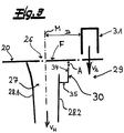
- the Fig. 1 shows a device according to the invention for producing a nonwoven fabric 1 from fibers made of thermoplastic material, the fibers preferably being continuous filaments 2 in the exemplary embodiment, specifically recommended and in the exemplary embodiment being bicomponent filaments with an eccentric core-sheath configuration.
- the device according to the invention is designed as a spunbond device for producing a spunbond nonwoven fabric.
- Fig. 1 shows a spinning device 10 for spinning the continuous filaments 2.
- the spun continuous filaments 2 are introduced into a cooling device 11 with a cooling chamber 12.
- air supply cabins 13, 14 arranged one above the other are arranged on two opposite sides of the cooling chamber 12. Air of different temperatures is expediently introduced into the cooling chamber 12 from these air supply cabins 13, 14 arranged one above the other.
- a monomer suction device 15 is arranged between the spinning device 10 and the cooling device 11. With this monomer suction device 15, interfering gases occurring during the spinning process can be removed from the device. With these gases it can are, for example, monomers, oligomers or decomposition products and similar substances.
- the cooling device 11 is followed by a stretching device 16 for stretching the continuous filaments 2.
- the stretching device 16 has an intermediate channel 17 which connects the cooling device 11 to a stretching shaft 18 of the stretching device 16.
- the unit from the cooling device 11 and the stretching device 16 or the unit from the cooling device 11, the intermediate channel 17 and the stretching shaft 18 is designed as a closed unit and, apart from the supply of cooling air in the cooling device 11, there is no further air supply from the outside into this unit.
- a diffuser 19 through which the continuous filaments 2 are guided, adjoins the stretching device 16 in the filament flow direction.
- the continuous filaments are deposited, preferably and in the exemplary embodiment, on a depositing conveyor designed as a depositing screen belt 20.
- the depositing screen belt 20 is preferred and, in the exemplary embodiment, is designed as an endlessly revolving depositing screen belt 20. It is within the scope of the invention that the screen belt 20 is designed to be air-permeable, so that process air can be extracted from below through the screen belt 20.
- the diffuser 19 or the diffuser 19 arranged directly above the depositing screen belt 20 has two opposite diffuser walls, two lower diverging diffuser wall sections 21, 22 being provided, which are preferred and in the exemplary embodiment are formed asymmetrically with respect to the central plane M of the diffuser 20.
- the inlet-side diffuser wall section 21 or the sieve belt-side end of the inlet-side diffuser section 21 has a smaller distance e 1 to the center plane M of the diffuser 19 or the device than the distance e 2 of the outlet-side diffuser wall section 22 or the sieve belt-side end of the outlet-side diffuser section 22.
- inlet-side diffuser section 21 forms a smaller angle ⁇ with center plane M of diffuser 19 or the device than opposite outlet-side diffuser wall section 22.
- two opposite secondary air inlet gaps 24, 25 are provided at the inflow end 23 of the diffuser 19, each of which is arranged on one of the two opposite diffuser walls.
- a lower secondary air volume flow can preferably be introduced through the secondary air inlet gap 24 on the inlet side with respect to the conveying direction of the depositing screen belt 20 than through the secondary air inlet gap 25 on the outlet side.
- the main suction area 27 is delimited below the depositing screen belt 20 in an inlet area of the depositing screen belt 20 and in an outlet area of the depositing screen belt 20 by a suction partition 28.1, 28.2.
- At least one, in particular a suction partition 28.1, 28.2 has a partition section designed as a spoiler section 30 at its end on the conveyor side.
- a partition section which is angled from the remaining suction partition 28.2 and is designed as a spoiler section 30.
- the spoiler section 30 is, as it were, an integral part of the outlet-side suction partition 28.2 and is only designed as an angled partition section of this suction partition 28.2.
- the vertical distance A of the conveyor-side end of the spoiler section 30 to the depositing screen belt 20 is between 10 mm and 250 mm, according to a preferred embodiment between 18 mm and 120 mm.
- the spoiler section 30 is preferred and in the embodiment according to the Figures 1 and 2 angled to the side of the associated suction partition 28.2 facing away from the center of the main suction area 27.
- the Fig. 3 shows a further embodiment of a spoiler section 30.
- the spoiler section 30 is connected here as a separate angle element to the suction partition 28.2 on the outlet side.
- the angle element is preferably composed, in the exemplary embodiment, of only two spoiler components 34, 35 arranged at an angle to one another. Appropriately, and in the exemplary embodiment, the two spoiler components 34, 35 are oriented at right angles to one another.
- One spoiler component 34 of the spoiler section 30 is preferably oriented perpendicular to the storage conveyor surface F of the storage screen belt 20 and the other spoiler component 35 is oriented parallel to the storage conveyor surface F.
- the end of the spoiler section 30 on the conveyor side also has the Distance A according to the invention to the depositing conveyor or to the depositing screen belt 20.
- a second suction area 29 is connected downstream of the main suction area 27 in the conveying direction of the depositing screen belt 20, in which air or process air is sucked through the depositing screen belt 20.
- the suction speed v 2 of the process air through the depositing screen belt 20 in the second suction area 29 is lower than the suction speed v H in the main suction area 27.
- At least one thermal pre-consolidation device for thermal pre-consolidation of the nonwoven web is provided in the conveying direction of the nonwoven web after the deposit area 26 or after the main suction region 27. Furthermore, it is within the scope of the invention that this thermal pre-consolidation device is arranged on or above the second suction area 29. According to a particularly preferred embodiment, the thermal pre-consolidation device works with hot air and particularly preferably this thermal pre-consolidation device downstream of the main suction area 27 is a hot air knife 31. In principle, however, another pre-consolidation device or hot air pre-consolidation device could also be used.
- the thermal pre-consolidation device or hot air pre-consolidation device bonding points between the filaments 2 of the nonwoven web can be realized in a simple manner.
- the distance B is expediently ( Figures 2 and 3 ) between the center plane M of the diffuser 19 or the device and the first hot air pre-consolidation device - in particular in the form of the hot air knife 31 - 120 mm to 550 mm.
- At least two thermal pre-consolidation devices are provided for pre-consolidation of the nonwoven web.
- the Fig. 1 shows here a preferred embodiment.
- the first thermal preconsolidation device in the conveying direction of the nonwoven web is a hot air knife 31, and a second thermal preconsolidation device in the form of a hot air oven 32 is preferably connected downstream of this hot air knife 31 in the conveying direction of the depositing screen belt 20.
- air is sucked through the sieve belt 20 in the area of the hot air oven 32 as well.
- the suction speed of the air sucked off by the depositing screen belt 20 decreases from the main suction area 27 to the other suction areas in the conveying direction of the depositing screen belt 20.
- the spoiler section 30 is achieved that a continuous, as it were, smooth transition of the suction speeds from the main suction area 27 to the second suction area 29 takes place.
- the spoiler section 30 is in the embodiment according to Figures 1 to 3 aligned or angled to that of the center of the main suction area 27 or to the side of the associated suction partition 28.2 facing away from the center plane M.
- the spoiler section 30 is more angled with respect to a vertical V oriented perpendicular to the storage conveyor surface F than a partition section of the further opposite suction partition 28.1 facing the storage screen belt 20.
- the Fig. 2 also shows that, according to a preferred embodiment, the spoiler section 30 in its projection onto the depositing conveyor surface F has a greater length L than the corresponding projection of an angled or bent towards the depositing screen belt 20. bent partition wall section of the further opposite suction partition 28.1.
- the spoiler section 30 has a greater vertical distance A from the screen belt 20 with respect to its end on the screen belt side than the end of the partition section of the further opposite suction partition 28.1 facing the screen belt 20.
- the vertical height h of the spoiler section 30 is preferably 5 mm to 110 mm, in particular 15 mm to 100 mm.
- a spoiler section 30 ensures a very even and continuous transition of the suction speeds from the main suction area 27 to the area following in the conveying direction of the depositing screen belt 20 and in particular to the second suction area 29. Due to the arrangement of the spoiler section 30, a gradual, continuous steady decrease in the suction speed can be achieved. That is based on the Fig. 4 explained below. As a result of the gradual, continuous decrease in the suction speed, defects in the nonwoven web or in the spunbond nonwoven fabric 1 according to the invention, which can result from abrupt changes in the suction speed, can be avoided.
- blow-back effects in the transition area between the main suction area 27 and the second suction area 29 can be avoided, which in devices known from the prior art lead to disadvantageous inhomogeneities of the nonwoven web and in particular to disruptive filament agglomerates.
- the Fig. 4 shows schematically the suction speed v through the depositing screen belt 20 at various positions along the depositing screen belt 20 in Transition area between the main suction area 27 and the second suction area 29.
- the suction speed was measured in a 10 cm grid with a vane anemometer with a diameter of 80 mm, directly above the depositing screen belt 20 (0 mm to 5 mm distance from the depositing screen belt 20).
- the maximum on the left corresponds to the high suction speed v H in the main suction area 27 and the more or less horizontal curves on the right show the suction speed v 2 in the second suction area 29.
- Curves K1 and K2 correspond to the decrease in suction speed in conventional spunbond devices without spoiler section 30 according to the invention.
- Curves K3 illustrate the decrease in suction speed for a spunbond device according to the invention with spoiler section 30, namely at different suction speeds v 2 .
- an angled spoiler section 30 has been made accordingly Fig. 2 used. It can be seen that the suction speeds for the conventional spunbond devices (curves K1 and K2) drop very abruptly in the transition area between the main suction area 27 and the second suction area 29.
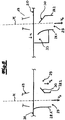
- the Fig. 5 shows a two-bar system with two spunbond devices according to the invention connected one behind the other, which preferably and in the exemplary embodiment each deposit continuous filaments 2 on the same screen belt 20 to form the nonwoven web.
- a laminate of two nonwoven webs or two spunbond nonwovens 1 is produced with this system.
- this system could also be part of a multi-beam system with further spinning devices 10.
- Fig. 5 not the complete spunbond devices shown, but only the lower part with the diffuser 19 arranged above the filing screen belt 20. It is within the scope of the invention that both spunbond devices above the filing screen belt 20 have a structure corresponding to the spunbond device Fig. 1 exhibit. - At the first bar or at the first spinning device 10 on the left in the Fig. 5 A first spoiler section 30 is connected to the outlet-side suction partition 28.2 of the main suction area 27 and, preferably and in the exemplary embodiment, this spoiler section 30 is angled to the side of the connected suction partition 28.2 facing away from the center of this left main suction area 27.
- the first deposited nonwoven web then preferably runs through two thermal hot air pre-consolidation devices, which are preferably designed as a hot air knife 31 and as a hot air oven 32 connected downstream of this hot air knife 31.
- the pre-consolidation devices are in Fig. 5 not shown.
- a further nonwoven web on the second bar or on the second spinning device 10 on the right-hand side.
- This second nonwoven web is placed on the first nonwoven web.
- the arrangement of the spoiler section 30 differs from that of the first bar.
- the second spoiler section 30 is also connected to the suction partition 28.2 of the main suction area 27 on the outlet side.
- This second spoiler section 30 of the second bar is angled towards the center of the second main suction area 27 in contrast to the first bar.
- the main suction area 27 is preceded by a further suction area 33, in which process air is sucked through the depositing screen belt 20 at a suction speed vv.
- This suction speed vv of the upstream suction area 33 is smaller or significantly smaller than the suction speed v H of the following main suction area 27.
- the spoiler section 30 is open at this second bar angled towards the center of the main suction area 27 in the manner described. This also ensures a smooth, continuous transition of the suction speeds from the upstream suction area 33 to the main suction area 27.
- the Fig. 6 shows a cross section through an endless filament 2 with a special core-sheath configuration.
- the production of nonwovens 1 from these continuous filaments 2 has been found in connection with the invention Device and particularly proven with the method according to the invention.
- the sheath 3 preferably has a constant thickness d in the filament cross section and in the exemplary embodiment over more than 50%, preferably over more than 55% of the filament circumference.
- the core 4 of the filaments 2 takes up more than 65% of the area of the filament cross-section of the filaments 2.
- the core 4 - viewed in the filament cross section - is configured in the shape of a segment of a circle.
- this core 4 has an arcuate circumferential section 5 and a linear circumferential section 6 with respect to its circumference.
- the circular arc-shaped circumferential section of the core 4 takes up over 50%, preferably over 55% of the circumference of the core 4.
- the jacket 3 of the filaments 2 - viewed in the filament cross section - is designed in the shape of a segment of a circle outside the jacket area with the constant thickness d.
- This circular segment 7 of the jacket 3 has, as recommended and in the exemplary embodiment with regard to its circumference, a circular arc-shaped circumferential section 8 and a linear circumferential section 9.
- the thickness d or the mean thickness d of the jacket 3 in the region of its constant thickness is preferably 1% to 8%, in particular 2% to 10% of the filament diameter D.
- the thickness d of the jacket 3 in the region of its constant thickness may be 0 , 2 ⁇ m to 3 ⁇ m.
- the Fig. 6 shows the distance a of the centroid of the core 4 from the centroid of the sheath 3 of the continuous filament 2.
- This distance a of the centroids of the core 4 and sheath 3 is regularly greater for a given mass ratio of core and sheath material for the continuous filaments 2 preferred here than for conventional continuous filaments 2 with an eccentric core-sheath configuration.
- the distance a the centroid of the core 4 from the centroid of the sheath 3 in the case of the filaments 2 present here is preferably 5% to 40% of the filament diameter D or the largest filament diameter D.
Landscapes
- Engineering & Computer Science (AREA)
- Textile Engineering (AREA)
- Chemical & Material Sciences (AREA)
- Mechanical Engineering (AREA)
- Chemical Kinetics & Catalysis (AREA)
- Inorganic Chemistry (AREA)
- Nonwoven Fabrics (AREA)
- Spinning Methods And Devices For Manufacturing Artificial Fibers (AREA)
- Yarns And Mechanical Finishing Of Yarns Or Ropes (AREA)
Claims (20)
- Dispositif, destiné à fabriquer un non-tissé (1) en fibres, notamment en fibres d'une matière thermoplastique, au moins un système de filage (10) pour filer les fibres et un convoyeur de dépose perméable à l'air (notamment une toile perforée de dépose (20)) pour y déposer les fibres en formant une bande de voile ou le non-tissé (1) étant prévus,
au moins un système d'aspiration étant présent, à l'aide duquel dans la zone de dépose (26) des fibres, dans une zone d'aspiration principale (27), de l'air ou de l'air de processus est susceptible d'être aspiré à travers le convoyeur de dépose, la zone d'aspiration principale (27) en-dessous du convoyeur de dépose étant délimitée dans une zone d'entrée du convoyeur de dépose et dans une zone de sortie du convoyeur de dépose par chaque fois une paroi aspirante de séparation (28.1, 28.2),
l'extrémité côté convoyeur d'au moins une, notamment d'une paroi aspirante de séparation (28.1, 28.2) ou une partie de la paroi aspirante de séparation (28.1, 28.2) concernée, placée avec l'écart vertical le plus court par rapport au convoyeur de dépose présentant un écart vertical A par rapport au convoyeur de dépose compris entre 10 mm et 250 mm, notamment compris entre 25 mm et 200 mm, de préférence compris entre 28 mm et 150 mm, de manière préférentielle compris entre 29 mm et 120 mm et de manière très préférentielle, compris entre 30 mm et 120 mm,
au moins une, notamment une paroi aspirante de séparation (28.1, 28.2) comprenant sur son extrémité côté convoyeur un segment de paroi de séparation coudé à partir de la paroi aspirante de séparation (28.1, 28.2) restante, conçu en tant que segment en becquet (30) et l'extrémité côté convoyeur du segment en becquet (30) ou une partie du segment en becquet (30) placée avec l'écart vertical le plus court par rapport au convoyeur de dépose présentant l'écart vertical A par rapport au convoyeur de dépose
et le segment en becquet (30)- étant coudé plus fortement par rapport à une verticale V orientée à la perpendiculaire de la surface du convoyeur de dépose F qu'un segment de paroi de séparation côté convoyeur de dépose de la paroi aspirante de séparation (28.1, 28.2) restante ou opposée- et/ou dans sa projection sur la surface du convoyeur de dépose F, présentant une longueur L supérieure à celle de la projection correspondante d'un segment de paroi de séparation côté convoyeur de dépose de la paroi aspirante de séparation (28.1, 28.2) restante ou opposée- et/ou par rapport à son extrémité côté convoyeur, présentant un écart A par rapport au convoyeur de dépose supérieur à celui de l'extrémité côté convoyeur du segment de paroi de séparation côté convoyeur de dépose de la paroi aspirante de séparation (28.1, 28.2) restante ou opposée. - Dispositif selon la revendication 1, au moins une, notamment une paroi aspirante de séparation (28.1, 28.2) comprenant sur son extrémité côté convoyeur un segment de becquet (30) sous la forme d'un élément coudé, pourvu d'au moins deux composants de becquet (34, 35) placés en formant entre eux un coude et l'extrémité côté convoyeur dudit segment en becquet (30) ou une partie dudit segment de becquet (30) avec l'écart vertical le plus court par rapport au convoyeur de dépose présentant l'écart vertical A par rapport au convoyeur de dépose.
- Dispositif selon la revendication 2, le segment en becquet (30) comportant un composant de becquet (34) qui est orienté à la transversale, notamment à la perpendiculaire ou sensiblement à la perpendiculaire de la surface du convoyeur de dépose F et le segment en becquet (30) comportant par ailleurs un composant de becquet (35) qui est orienté à la parallèle ou sensiblement à la parallèle de la surface du convoyeur de dépose F.
- Dispositif selon l'une quelconque des revendications 1 à 3, seule une paroi aspirante de séparation (28.1, 28.2) comportant sur son extrémité côté convoyeur le segment en becquet (30) et de préférence ledit segment en becquet (30) étant prévu sur la paroi aspirante de séparation (28.2) côté sortie.
- Dispositif selon l'une quelconque des revendications 1 à 4, le segment en becquet (30) étant orienté ou coudé vers le côté opposé au centre de la zone d'aspiration principale (27) de la paroi aspirante de séparation (28.1, 28.2) associée ou le segment en becquet (30) étant orienté ou coudé vers le centre de la zone d'aspiration principale (27).
- Dispositif selon l'une quelconque des revendications 1 à 5, au moins deux systèmes de filage (10) ou barres de filage étant prévu(e)s pour filer les fibres, à chaque système de filage (10) ou à chaque barre de filage étant associée une zone d'aspiration principale (27) dans laquelle de l'air ou de l'air de processus est susceptible d'être aspiré à travers le convoyeur de dépose, chacune desdites zones d'aspiration principales (27) étant délimitée par deux parois aspirantes de séparation (28.1, 28.2), au moins une paroi aspirante de séparation (28.1, 28.2) de chaque zone d'aspiration principale (27) comportant un segment en becquet (30),
un premier segment en becquet (30) d'une première zone d'aspiration principale (27) par rapport à la direction de convoyage du convoyeur de dépose (de préférence un segment en becquet (30) raccordé sur la paroi aspirante de séparation (28.2) côté sortie de ladite première zone d'aspiration principale (27)) étant orienté ou coudé vers le côté de la paroi aspirante de séparation (28.1, 28.2) raccordée qui est opposé au centre de ladite première zone d'aspiration principale (27),
et un deuxième segment en becquet (30) d'une deuxième zone d'aspiration principale (27) placée en aval, par rapport à la direction de convoyage du convoyeur de dépose (de préférence un segment en becquet (30) raccordé sur la paroi aspirante de séparation (28.2) côté sortie de ladite deuxième zone d'aspiration principale (27)) étant orienté ou coudé vers le centre de ladite deuxième zone d'aspiration principale (27). - Dispositif selon l'une quelconque des revendications 1 à 6, le dispositif étant aménagé sous la forme d'un dispositif de filage-nappage, destiné à fabriquer des non-tissés filés-nappés en filaments continus (2) et notamment en filaments continus (2) crêpés.
- Dispositif selon la revendication 7, le dispositif comportant au moins un dispositif de refroidissement (11), placé en aval du système de filage (10) et au moins un dispositif d'étirage (16), placé en aval du dispositif de refroidissement (11), ainsi qu'au moins un diffuseur (19), placé en aval du dispositif d'étirage (16) .
- Dispositif selon la revendication 8, l'ensemble comprenant le dispositif de refroidissement (11) et le dispositif d'étirage (16) étant conçu sous la forme d'un ensemble fermé et hormis l'apport d'air de refroidissement dans le dispositif de refroidissement (11), aucun apport d'air supplémentaire à partir de l'extérieur n'ayant lieu dans ledit ensemble.
- Dispositif selon l'une quelconque des revendications 1 à 9, un diffuseur (19) placé directement au-dessus du convoyeur de dépose comportant deux parois de diffuseur opposées, deux segments inférieurs de paroi de diffuseur (21, 22) divergents étant prévus, qui sont placés de préférence de manière asymétrique par rapport au plan médian du diffuseur (19) ou du dispositif et notamment le segment de paroi de diffuseur (21) côté entrée formant avec le plan médian M du diffuseur (19) ou du dispositif un angle β inférieur à celui formé par le segment de paroi de diffuseur (22) côté sortie.
- Dispositif selon l'une quelconque des revendications 1 à 10, un diffuseur (19) placé directement au-dessus du convoyeur de dépose comportant deux parois de diffuseur opposées, sur l'extrémité d'affluence (23) du diffuseur (19) étant prévus au moins deux interstices d'entrée d'air secondaire (24, 25) opposés, qui sont placés chacun sur l'une des deux parois de diffuseur opposées et de préférence à travers l'interstice d'entrée d'air secondaire (24) côté entrée par rapport à la direction de convoyage du convoyeur de dépose étant susceptible d'être introduit un flux volumétrique d'air secondaire plus faible qu'à travers l'interstice d'entrée d'air secondaire (25) côté sortie.
- Dispositif selon l'une quelconque des revendications 1 à 11, en aval de la zone d'aspiration principale (27) dans la direction de convoyage du convoyeur de dépose étant placée une deuxième zone d'aspiration (29), dans laquelle de l'air ou de l'air de processus est susceptible d'être aspiré à travers le convoyeur de dépose et/ou en amont de la zone d'aspiration principale (27) par rapport à la direction de convoyage du convoyeur de dépose étant placée une zone d'aspiration (33) antérieure, dans laquelle de l'air ou de l'air de processus est susceptible d'être aspiré à travers le convoyeur de dépose,
de préférence la deuxième zone d'aspiration (29) étant aménagée avec le critère que la vitesse d'aspiration v2 de l'air de processus à travers le convoyeur de dépose dans la deuxième zone d'aspiration soit inférieure à la vitesse d'aspiration VH dans la zone d'aspiration principale (27),
et/ou de préférence la zone d'aspiration (33) antérieure étant aménagée avec le critère que la vitesse d'aspiration Vv de l'air de processus à travers le convoyeur de dépose dans la zone d'aspiration (33) antérieure soit inférieure à la vitesse d'aspiration VH dans la zone d'aspiration principale (27). - Dispositif selon la revendication 12, au moins un segment en becquet (30) d'au moins une paroi aspirante de séparation (28.1, 28.2) de la zone d'aspiration principale (27) et notamment un segment en becquet (30) de la paroi aspirante de séparation (28.2) côté sortie étant agencé et/ou placé et/ou orienté de sorte qu'ait lieu un passage constant continu de la vitesse d'aspiration VH de la zone d'aspiration principale (27) vers la vitesse d'aspiration V2 de la deuxième zone d'aspiration (29) et/ou qu'ait lieu un passage constant continu de la vitesse d'aspiration Vv de la zone d'aspiration (33) antérieure vers la vitesse d'aspiration VH de la zone d'aspiration principale (27).
- Dispositif selon l'une quelconque des revendications 12 ou 13, sur ou au-dessus de la deuxième zone d'aspiration (29) étant placé un système de préconsolidation pour préconsolider le non-tissé (1).
- Dispositif selon la revendication 14, l'écart B entre le plan médian M du diffuseur (19) et le système de préconsolidation étant de 100 mm à 1.000 mm, notamment de 110 mm à 600 mm et de manière préférentielle, de 120 mm à 550 mm.
- Procédé, destiné à fabriquer un non-tissé (1) en fibres, notamment en fibres en une matière thermoplastique (de préférence au moyen d'un dispositif selon l'une quelconque des revendications 1 à 15), les fibres étant filées et déposées sur un convoyeur de dépose perméable à l'air, notamment une toile perforée de dépose (20) en formant une bande de voile ou le non-tissé (1), dans la zone de dépose (26) des fibres, dans une zone d'aspiration principale (27), de l'air ou de l'air de processus étant aspiré par le bas à travers le convoyeur de dépose, la zone d'aspiration principale (27) étant délimitée par deux parois aspirantes de séparation (28.1, 28.2),
une zone d'aspiration (33) placée en amont de la zone d'aspiration principale (27) ou de la paroi aspirante de séparation (28.1) côté entrée, par rapport à la direction de convoyage du convoyeur de dépose étant prévue et/ou une deuxième zone d'aspiration (29) placée en aval de la zone d'aspiration principale (27) ou de la paroi aspirante de séparation (28.2) côté sortie étant prévue,
dans la zone d'aspiration (33) antérieure et/ou dans la deuxième zone d'aspiration (29) placée en aval, de l'air étant aspiré à travers le convoyeur de dépose à une vitesse d'aspiration plus faible à celle dans la zone d'aspiration principale (27)
et au moins un segment de paroi de séparation côté convoyeur d'une paroi aspirante de séparation (28.1, 28.2) étant orienté ou coudé avec le critère, notamment un segment en becquet (30) coudé sur l'extrémité côté convoyeur d'une paroi aspirante de séparation (28.1, 28.2) étant placé ou orienté avec le critère
que la vitesse d'aspiration de l'air aspiré à travers le convoyeur de dépose croisse constamment en continu de la zone d'aspiration (33) antérieure vers la zone d'aspiration principale (27) et/ou décroisse constamment en continu de la zone d'aspiration principale (27) vers la deuxième zone d'aspiration (29) placée en aval,
et la vitesse d'aspiration VH dans la zone d'aspiration principale (27) étant supérieure de 1,5 à 4 fois, de manière préférentielle de 2 à 4 fois, de manière très préférentielle de 2,5 à 3,5 fois à la vitesse d'aspiration Vv dans la zone d'aspiration (33) antérieure et/ou à la vitesse d'aspiration V2 dans la deuxième zone d'aspiration (29) placée en aval. - Procédé selon la revendication 16, un non-tissé filénappé étant fabriqué en filaments continus (2), notamment en filaments continus (2) crêpés, les filaments continus (2) étant filés de préférence sous la forme de filaments bicomposants ou de filaments multicomposants et de manière préférentielle, des filaments bicomposants ou des filaments multicomposants à configuration âme-enveloppe excentrique étant filés.
- Procédé selon l'une quelconque des revendications 16 ou 17, la chute de la vitesse d'aspiration de VH à V2 présentant une pente de 1 à 8 m/s, de manière préférentielle de 2 à 6 m/s par 10 cm dans la direction de la machine (MD) ou dans la direction de convoyage du non-tissé (1).
- Procédé selon l'une quelconque des revendications 16 à 18, la vitesse d'aspiration de la vitesse d'aspiration VH dan s la zone d'aspiration principale (27) vers la vitesse d'aspiration V2 dans la deuxième zone d'aspiration (29) placée en aval décroissant constamment en continu ou de manière linéaire en continu dans une zone de passage d'une longueur d'au moins 10 cm, notamment d'au moins 16 cm et de préférence d'au moins 18 cm.
- Procédé selon l'une quelconque des revendications 16 à 19, la vitesse d'aspiration de la vitesse d'aspiration Vv dans la zone d'aspiration (33) antérieure vers la vitesse d'aspiration VH dans la zone d'aspiration principale (27) croissant constamment en continu dans une zone de passage d'une longueur d'au moins 10 cm, notamment d'au moins 16 cm.
Priority Applications (14)
| Application Number | Priority Date | Filing Date | Title |
|---|---|---|---|
| PL19189208T PL3771762T3 (pl) | 2019-07-30 | 2019-07-30 | Urządzenie i sposób do wytwarzania włókniny z włókien |
| DK19189208.2T DK3771762T3 (da) | 2019-07-30 | 2019-07-30 | Indretning og fremgangsmåde til fremstilling af et vliesstof af fibre |
| ES19189208T ES2886885T3 (es) | 2019-07-30 | 2019-07-30 | Dispositivo y procedimiento para la fabricación de un material no tejido a partir de fibras |
| EP19189208.2A EP3771762B1 (fr) | 2019-07-30 | 2019-07-30 | Dispositif et pro cédé de fabrication d'un non-tissé de fibre |
| BR102020014090-6A BR102020014090A2 (pt) | 2019-07-30 | 2020-07-09 | Dispositivo e processo para produção de um material tnt a partir de fibras |
| JP2020120531A JP7096294B2 (ja) | 2019-07-30 | 2020-07-14 | 繊維から不織布を製造するための装置及び方法 |
| RU2020123971A RU2759705C1 (ru) | 2019-07-30 | 2020-07-20 | Устройство и способ изготовления нетканого материала из волокон |
| IL276307A IL276307B (en) | 2019-07-30 | 2020-07-26 | Device and method for fabricating a non-woven fabric from fibers |
| US16/940,884 US11618983B2 (en) | 2019-07-30 | 2020-07-28 | Making a nonwoven from filaments |
| KR1020200094718A KR102518198B1 (ko) | 2019-07-30 | 2020-07-29 | 섬유로부터 부직포를 제조하는 장치 및 방법 |
| ARP200102123A AR119513A1 (es) | 2019-07-30 | 2020-07-29 | Dispositivo y procedimiento para producir un material no tejido a partir de fibras |
| CN202010741474.7A CN112301553B (zh) | 2019-07-30 | 2020-07-29 | 用于制造由纤维制成的无纺布的设备和方法 |
| MX2020008055A MX2020008055A (es) | 2019-07-30 | 2020-07-30 | Dispositivo y metodo para producir una tela no tejida a partir de fibras. |
| ZA2020/04714A ZA202004714B (en) | 2019-07-30 | 2020-07-30 | Apparatus and method of making a nonwoven fabric from fibers |
Applications Claiming Priority (1)
| Application Number | Priority Date | Filing Date | Title |
|---|---|---|---|
| EP19189208.2A EP3771762B1 (fr) | 2019-07-30 | 2019-07-30 | Dispositif et pro cédé de fabrication d'un non-tissé de fibre |
Publications (2)
| Publication Number | Publication Date |
|---|---|
| EP3771762A1 EP3771762A1 (fr) | 2021-02-03 |
| EP3771762B1 true EP3771762B1 (fr) | 2021-06-16 |
Family
ID=67513428
Family Applications (1)
| Application Number | Title | Priority Date | Filing Date |
|---|---|---|---|
| EP19189208.2A Active EP3771762B1 (fr) | 2019-07-30 | 2019-07-30 | Dispositif et pro cédé de fabrication d'un non-tissé de fibre |
Country Status (14)
| Country | Link |
|---|---|
| US (1) | US11618983B2 (fr) |
| EP (1) | EP3771762B1 (fr) |
| JP (1) | JP7096294B2 (fr) |
| KR (1) | KR102518198B1 (fr) |
| CN (1) | CN112301553B (fr) |
| AR (1) | AR119513A1 (fr) |
| BR (1) | BR102020014090A2 (fr) |
| DK (1) | DK3771762T3 (fr) |
| ES (1) | ES2886885T3 (fr) |
| IL (1) | IL276307B (fr) |
| MX (1) | MX2020008055A (fr) |
| PL (1) | PL3771762T3 (fr) |
| RU (1) | RU2759705C1 (fr) |
| ZA (1) | ZA202004714B (fr) |
Family Cites Families (29)
| Publication number | Priority date | Publication date | Assignee | Title |
|---|---|---|---|---|
| US3402492A (en) | 1965-05-12 | 1968-09-24 | United States Radium Corp | Encapsulated radioactive light sources |
| JPS496786B1 (fr) * | 1970-12-23 | 1974-02-16 | ||
| DE3522208A1 (de) * | 1984-07-18 | 1986-01-23 | Ernst Dr. Linz Fehrer | Vorrichtung zum herstellen von faservliesen |
| GB2203764B (en) * | 1987-04-25 | 1991-02-13 | Reifenhaeuser Masch | Production of spun fleece from continuous synthetic filaments |
| DE19521466C2 (de) * | 1995-06-13 | 1999-01-14 | Reifenhaeuser Masch | Anlage für die Herstellung einer Spinnvliesbahn aus thermoplastischen Endlosfäden |
| DE19940333B4 (de) * | 1999-08-25 | 2004-03-25 | Reifenhäuser GmbH & Co Maschinenfabrik | Anlage für die Herstellung einer Spinnvliesbahn aus Kunststoffilamenten |
| US6499982B2 (en) * | 2000-12-28 | 2002-12-31 | Nordson Corporation | Air management system for the manufacture of nonwoven webs and laminates |
| ATE381630T1 (de) * | 2002-02-28 | 2008-01-15 | Reifenhaeuser Gmbh & Co Kg | Anlage zur kontinuierlichen herstellung einer spinnvliesbahn |
| DK1340842T4 (da) * | 2002-02-28 | 2011-03-28 | Reifenhaeuser Gmbh & Co Kg | Anlæg til kontinuerlig fremstilling af en fiberdugsbane |
| ATE374268T1 (de) | 2002-02-28 | 2007-10-15 | Reifenhaeuser Gmbh & Co Kg | Meltblown-anlage |
| US20060040008A1 (en) | 2004-08-20 | 2006-02-23 | Reifenhaeuser Gmbh & Co. Kg Maschinenfabrik | Device for the continuous production of a nonwoven web |
| US8137088B2 (en) * | 2004-09-24 | 2012-03-20 | Oerlikon Textile Gmbh & Co. Kg | Device for depositing synthetic fibers to form a nonwoven web |
| EP1726700B1 (fr) * | 2005-05-25 | 2013-02-27 | Reifenhäuser GmbH & Co. KG Maschinenfabrik | Procédé et dispositif pour la fabrication d'un non-tissé |
| CN101297074A (zh) * | 2005-10-26 | 2008-10-29 | 欧瑞康纺织有限及两合公司 | 将合成纤维铺放成无纺布的装置和方法 |
| EP1930492B1 (fr) * | 2006-12-06 | 2010-09-29 | Reifenhäuser GmbH & Co. KG Maschinenfabrik | Procédé et dispositif pour la fabrication d' un non-tissé de type spunbond |
| EP1939334B1 (fr) * | 2006-12-15 | 2010-02-24 | FARE' S.p.A. | Appareil et procédé pour la production d'une nappe de monofils continus désorientés |
| EP2099959B1 (fr) * | 2006-12-15 | 2014-02-12 | FARE' S.p.A. | Procédé et appareil pour la production d'un tissu de type spunbond |
| EP2111487A2 (fr) * | 2007-01-19 | 2009-10-28 | Oerlikon Textile GmbH & Co. KG | Appareil et procédé pour déposer des fibres synthétiques et former une bande non tissée |
| ATE502141T1 (de) * | 2007-01-31 | 2011-04-15 | Oerlikon Textile Gmbh & Co Kg | Verfahren und vorrichtung zur ansaugung und ablagerung mehrerer fasern zur formung eines vliesstoffs |
| US8037088B2 (en) | 2008-12-22 | 2011-10-11 | Oracle International Corporation | Change management |
| RU2507325C2 (ru) * | 2009-03-25 | 2014-02-20 | Торэй Индастриз, Инк. | Способ получения нетканого материала из волокна |
| EP2738297B1 (fr) * | 2012-12-03 | 2016-03-02 | Reifenhäuser GmbH & Co. KG Maschinenfabrik | Dispositif et procédé destinés à la fabrication d'une bande de non-tissé en filaments |
| DE102014002060B4 (de) * | 2014-02-18 | 2018-01-18 | Carl Freudenberg Kg | Volumenvliesstoffe, Verwendungen davon und Verfahren zu ihrer Herstellung |
| EP3372719B1 (fr) * | 2015-01-30 | 2019-11-20 | Reifenhäuser GmbH & Co. KG Maschinenfabrik | Dispositif de guidage de bande de non-tissé |
| DK3088585T3 (en) * | 2015-04-27 | 2017-09-25 | Reifenhäuser Gmbh & Co Kg Maschf | Method and apparatus for making a nonwoven fabric of filaments and nonwoven fabric |
| SI3239378T1 (sl) * | 2016-04-29 | 2019-06-28 | Reifenhaeuser Gmbh & Co. Kg Maschinenfabrik | Naprava in postopek za izdelavo kopren iz brezkončnih filamentov |
| PL3382081T3 (pl) * | 2017-03-31 | 2020-03-31 | Reifenhäuser GmbH & Co. KG Maschinenfabrik | Urządzenie do wytwarzania włóknin typu spunbond z filamentów bez końca |
| EP3575469B1 (fr) * | 2018-05-28 | 2020-08-05 | Reifenhäuser GmbH & Co. KG Maschinenfabrik | Procédé et dispositif destinés à la fabrication de tissus non-tissés à partir de filaments continus |
| DK3771763T3 (da) * | 2019-07-30 | 2022-03-07 | Reifenhaeuser Masch | Indretning og fremgangsmåde til fremstilling af et vliesstof af krusede fibre |
-
2019
- 2019-07-30 ES ES19189208T patent/ES2886885T3/es active Active
- 2019-07-30 PL PL19189208T patent/PL3771762T3/pl unknown
- 2019-07-30 DK DK19189208.2T patent/DK3771762T3/da active
- 2019-07-30 EP EP19189208.2A patent/EP3771762B1/fr active Active
-
2020
- 2020-07-09 BR BR102020014090-6A patent/BR102020014090A2/pt unknown
- 2020-07-14 JP JP2020120531A patent/JP7096294B2/ja active Active
- 2020-07-20 RU RU2020123971A patent/RU2759705C1/ru active
- 2020-07-26 IL IL276307A patent/IL276307B/en unknown
- 2020-07-28 US US16/940,884 patent/US11618983B2/en active Active
- 2020-07-29 KR KR1020200094718A patent/KR102518198B1/ko active IP Right Grant
- 2020-07-29 CN CN202010741474.7A patent/CN112301553B/zh active Active
- 2020-07-29 AR ARP200102123A patent/AR119513A1/es active IP Right Grant
- 2020-07-30 ZA ZA2020/04714A patent/ZA202004714B/en unknown
- 2020-07-30 MX MX2020008055A patent/MX2020008055A/es unknown
Non-Patent Citations (1)
| Title |
|---|
| None * |
Also Published As
| Publication number | Publication date |
|---|---|
| EP3771762A1 (fr) | 2021-02-03 |
| US20210032788A1 (en) | 2021-02-04 |
| IL276307B (en) | 2022-06-01 |
| JP7096294B2 (ja) | 2022-07-05 |
| JP2021025187A (ja) | 2021-02-22 |
| CN112301553A (zh) | 2021-02-02 |
| MX2020008055A (es) | 2021-12-02 |
| RU2759705C1 (ru) | 2021-11-17 |
| PL3771762T3 (pl) | 2021-11-08 |
| ZA202004714B (en) | 2021-09-29 |
| CN112301553B (zh) | 2022-10-14 |
| US11618983B2 (en) | 2023-04-04 |
| DK3771762T3 (da) | 2021-08-30 |
| BR102020014090A2 (pt) | 2021-02-09 |
| KR20210014602A (ko) | 2021-02-09 |
| KR102518198B1 (ko) | 2023-04-04 |
| IL276307A (en) | 2021-01-31 |
| ES2886885T3 (es) | 2021-12-21 |
| AR119513A1 (es) | 2021-12-22 |
Similar Documents
| Publication | Publication Date | Title |
|---|---|---|
| DE10065859B4 (de) | Verfahren und Vorrichtung zur Herstellung von im Wesentlichen endlosen feinen Fäden | |
| EP1930492B1 (fr) | Procédé et dispositif pour la fabrication d' un non-tissé de type spunbond | |
| EP3088585B1 (fr) | Procédé et dispositif de production d'un non-tissé en filaments et non-tissé | |
| EP1323852B1 (fr) | Dispositif de fabrication d'une nappe liée au filage (spunbonded) | |
| EP3199672B1 (fr) | Procede et dispositif destines a la fabrication de tissus non-tisses a partir de filaments continus | |
| EP1726700B1 (fr) | Procédé et dispositif pour la fabrication d'un non-tissé | |
| EP1630265B1 (fr) | Appareil pour la fabrication en continu d'un voile de tissé-lié | |
| EP3382081B1 (fr) | Dispositif de fabrication d'un tissu non-tissé à partir de filaments continus | |
| EP0598463B1 (fr) | Procédé et installation pour produire et coucher des faiseaux de filaments continus au moyen de force d'air | |
| EP3771763B1 (fr) | Dispositif et procédé de fabrication d'un non-tissé de fibres bouclées | |
| EP3575469B1 (fr) | Procédé et dispositif destinés à la fabrication de tissus non-tissés à partir de filaments continus | |
| EP2128320A1 (fr) | Procédé et dispositif destinés à la fabrication de tissus non tissés en filaments | |
| EP3771761B1 (fr) | Non-tissé obtenu par fusion-soufflage des filaments continus et dispositif de production de non-tissé obtenu par fusion-soufflage | |
| EP3771764B1 (fr) | Dispositif et procédé de fabrication d'un tissu non tissé | |
| EP3771556B1 (fr) | Stratifié non-tissé et procédé de fabrication d'un stratifié non-tissé | |
| EP3382080B1 (fr) | Procédé et dispositif de fabrication d'un non-tissé à partir de fibres | |
| EP2907909A1 (fr) | Installation de fabrication en continu d'une bande de non-tissé | |
| WO2001086041A1 (fr) | Procede et dispositif pour acheminer sans traction des corps moules continus | |
| EP3771762B1 (fr) | Dispositif et pro cédé de fabrication d'un non-tissé de fibre | |
| EP3575470B1 (fr) | Dispositif de fabrication d'un tissu non-tissé à partir de filaments continus | |
| EP3199671B1 (fr) | Dispositif destine a la fabrication de matieres non tissees | |
| EP3575468B1 (fr) | Procédé et dispositif destinés à la fabrication de tissus non-tissés à partir de filaments continus | |
| EP4001488B1 (fr) | Dispositif de fabrication de tissus non tissés à partir de filaments continus | |
| DE10302079B4 (de) | Vorrichtung und Verfahren zur Herstellung von gekräuselten Spinnvliesfasern oder gekräuselten schmelzgeblasenen Vliesfilamenten aus geschmolzenem thermoplastischen Material | |
| EP4123063B1 (fr) | Tête de buse destinée à la génération de filaments |
Legal Events
| Date | Code | Title | Description |
|---|---|---|---|
| STAA | Information on the status of an ep patent application or granted ep patent |
Free format text: STATUS: EXAMINATION IS IN PROGRESS |
|
| PUAI | Public reference made under article 153(3) epc to a published international application that has entered the european phase |
Free format text: ORIGINAL CODE: 0009012 |
|
| 17P | Request for examination filed |
Effective date: 20200406 |
|
| AK | Designated contracting states |
Kind code of ref document: A1 Designated state(s): AL AT BE BG CH CY CZ DE DK EE ES FI FR GB GR HR HU IE IS IT LI LT LU LV MC MK MT NL NO PL PT RO RS SE SI SK SM TR |
|
| AX | Request for extension of the european patent |
Extension state: BA ME |
|
| GRAJ | Information related to disapproval of communication of intention to grant by the applicant or resumption of examination proceedings by the epo deleted |
Free format text: ORIGINAL CODE: EPIDOSDIGR1 |
|
| STAA | Information on the status of an ep patent application or granted ep patent |
Free format text: STATUS: GRANT OF PATENT IS INTENDED |
|
| GRAP | Despatch of communication of intention to grant a patent |
Free format text: ORIGINAL CODE: EPIDOSNIGR1 |
|
| GRAS | Grant fee paid |
Free format text: ORIGINAL CODE: EPIDOSNIGR3 |
|
| INTG | Intention to grant announced |
Effective date: 20210301 |
|
| GRAA | (expected) grant |
Free format text: ORIGINAL CODE: 0009210 |
|
| STAA | Information on the status of an ep patent application or granted ep patent |
Free format text: STATUS: THE PATENT HAS BEEN GRANTED |
|
| AK | Designated contracting states |
Kind code of ref document: B1 Designated state(s): AL AT BE BG CH CY CZ DE DK EE ES FI FR GB GR HR HU IE IS IT LI LT LU LV MC MK MT NL NO PL PT RO RS SE SI SK SM TR |
|
| REG | Reference to a national code |
Ref country code: GB Ref legal event code: FG4D Free format text: NOT ENGLISH |
|
| REG | Reference to a national code |
Ref country code: CH Ref legal event code: EP |
|
| REG | Reference to a national code |
Ref country code: DE Ref legal event code: R096 Ref document number: 502019001619 Country of ref document: DE |
|
| REG | Reference to a national code |
Ref country code: AT Ref legal event code: REF Ref document number: 1402422 Country of ref document: AT Kind code of ref document: T Effective date: 20210715 |
|
| REG | Reference to a national code |
Ref country code: IE Ref legal event code: FG4D Free format text: LANGUAGE OF EP DOCUMENT: GERMAN |
|
| REG | Reference to a national code |
Ref country code: SE Ref legal event code: TRGR |
|
| REG | Reference to a national code |
Ref country code: NL Ref legal event code: FP |
|
| REG | Reference to a national code |
Ref country code: DK Ref legal event code: T3 Effective date: 20210824 |
|
| REG | Reference to a national code |
Ref country code: GR Ref legal event code: EP Ref document number: 20210402011 Country of ref document: GR Effective date: 20210915 |
|
| REG | Reference to a national code |
Ref country code: LT Ref legal event code: MG9D |
|
| PG25 | Lapsed in a contracting state [announced via postgrant information from national office to epo] |
Ref country code: HR Free format text: LAPSE BECAUSE OF FAILURE TO SUBMIT A TRANSLATION OF THE DESCRIPTION OR TO PAY THE FEE WITHIN THE PRESCRIBED TIME-LIMIT Effective date: 20210616 Ref country code: LT Free format text: LAPSE BECAUSE OF FAILURE TO SUBMIT A TRANSLATION OF THE DESCRIPTION OR TO PAY THE FEE WITHIN THE PRESCRIBED TIME-LIMIT Effective date: 20210616 Ref country code: FI Free format text: LAPSE BECAUSE OF FAILURE TO SUBMIT A TRANSLATION OF THE DESCRIPTION OR TO PAY THE FEE WITHIN THE PRESCRIBED TIME-LIMIT Effective date: 20210616 Ref country code: BG Free format text: LAPSE BECAUSE OF FAILURE TO SUBMIT A TRANSLATION OF THE DESCRIPTION OR TO PAY THE FEE WITHIN THE PRESCRIBED TIME-LIMIT Effective date: 20210916 |
|
| REG | Reference to a national code |
Ref country code: SK Ref legal event code: T3 Ref document number: E 38163 Country of ref document: SK |
|
| PG25 | Lapsed in a contracting state [announced via postgrant information from national office to epo] |
Ref country code: LV Free format text: LAPSE BECAUSE OF FAILURE TO SUBMIT A TRANSLATION OF THE DESCRIPTION OR TO PAY THE FEE WITHIN THE PRESCRIBED TIME-LIMIT Effective date: 20210616 Ref country code: NO Free format text: LAPSE BECAUSE OF FAILURE TO SUBMIT A TRANSLATION OF THE DESCRIPTION OR TO PAY THE FEE WITHIN THE PRESCRIBED TIME-LIMIT Effective date: 20210916 Ref country code: RS Free format text: LAPSE BECAUSE OF FAILURE TO SUBMIT A TRANSLATION OF THE DESCRIPTION OR TO PAY THE FEE WITHIN THE PRESCRIBED TIME-LIMIT Effective date: 20210616 |
|
| REG | Reference to a national code |
Ref country code: ES Ref legal event code: FG2A Ref document number: 2886885 Country of ref document: ES Kind code of ref document: T3 Effective date: 20211221 |
|
| PG25 | Lapsed in a contracting state [announced via postgrant information from national office to epo] |
Ref country code: SM Free format text: LAPSE BECAUSE OF FAILURE TO SUBMIT A TRANSLATION OF THE DESCRIPTION OR TO PAY THE FEE WITHIN THE PRESCRIBED TIME-LIMIT Effective date: 20210616 Ref country code: PT Free format text: LAPSE BECAUSE OF FAILURE TO SUBMIT A TRANSLATION OF THE DESCRIPTION OR TO PAY THE FEE WITHIN THE PRESCRIBED TIME-LIMIT Effective date: 20211018 Ref country code: RO Free format text: LAPSE BECAUSE OF FAILURE TO SUBMIT A TRANSLATION OF THE DESCRIPTION OR TO PAY THE FEE WITHIN THE PRESCRIBED TIME-LIMIT Effective date: 20210616 Ref country code: EE Free format text: LAPSE BECAUSE OF FAILURE TO SUBMIT A TRANSLATION OF THE DESCRIPTION OR TO PAY THE FEE WITHIN THE PRESCRIBED TIME-LIMIT Effective date: 20210616 |
|
| REG | Reference to a national code |
Ref country code: DE Ref legal event code: R097 Ref document number: 502019001619 Country of ref document: DE |
|
| PG25 | Lapsed in a contracting state [announced via postgrant information from national office to epo] |
Ref country code: MC Free format text: LAPSE BECAUSE OF FAILURE TO SUBMIT A TRANSLATION OF THE DESCRIPTION OR TO PAY THE FEE WITHIN THE PRESCRIBED TIME-LIMIT Effective date: 20210616 |
|
| PLBE | No opposition filed within time limit |
Free format text: ORIGINAL CODE: 0009261 |
|
| STAA | Information on the status of an ep patent application or granted ep patent |
Free format text: STATUS: NO OPPOSITION FILED WITHIN TIME LIMIT |
|
| 26N | No opposition filed |
Effective date: 20220317 |
|
| PG25 | Lapsed in a contracting state [announced via postgrant information from national office to epo] |
Ref country code: LU Free format text: LAPSE BECAUSE OF NON-PAYMENT OF DUE FEES Effective date: 20210730 Ref country code: AL Free format text: LAPSE BECAUSE OF FAILURE TO SUBMIT A TRANSLATION OF THE DESCRIPTION OR TO PAY THE FEE WITHIN THE PRESCRIBED TIME-LIMIT Effective date: 20210616 |
|
| PG25 | Lapsed in a contracting state [announced via postgrant information from national office to epo] |
Ref country code: IE Free format text: LAPSE BECAUSE OF NON-PAYMENT OF DUE FEES Effective date: 20210730 |
|
| PG25 | Lapsed in a contracting state [announced via postgrant information from national office to epo] |
Ref country code: CY Free format text: LAPSE BECAUSE OF FAILURE TO SUBMIT A TRANSLATION OF THE DESCRIPTION OR TO PAY THE FEE WITHIN THE PRESCRIBED TIME-LIMIT Effective date: 20210616 |
|
| P01 | Opt-out of the competence of the unified patent court (upc) registered |
Effective date: 20230526 |
|
| PG25 | Lapsed in a contracting state [announced via postgrant information from national office to epo] |
Ref country code: HU Free format text: LAPSE BECAUSE OF FAILURE TO SUBMIT A TRANSLATION OF THE DESCRIPTION OR TO PAY THE FEE WITHIN THE PRESCRIBED TIME-LIMIT; INVALID AB INITIO Effective date: 20190730 |
|
| PGFP | Annual fee paid to national office [announced via postgrant information from national office to epo] |
Ref country code: CZ Payment date: 20230621 Year of fee payment: 5 |
|
| PGFP | Annual fee paid to national office [announced via postgrant information from national office to epo] |
Ref country code: SK Payment date: 20230621 Year of fee payment: 5 Ref country code: PL Payment date: 20230623 Year of fee payment: 5 Ref country code: NL Payment date: 20230724 Year of fee payment: 5 |
|
| PGFP | Annual fee paid to national office [announced via postgrant information from national office to epo] |
Ref country code: TR Payment date: 20230726 Year of fee payment: 5 Ref country code: IT Payment date: 20230727 Year of fee payment: 5 Ref country code: GB Payment date: 20230720 Year of fee payment: 5 Ref country code: ES Payment date: 20230801 Year of fee payment: 5 Ref country code: CH Payment date: 20230801 Year of fee payment: 5 |
|
| PGFP | Annual fee paid to national office [announced via postgrant information from national office to epo] |
Ref country code: SE Payment date: 20230721 Year of fee payment: 5 Ref country code: GR Payment date: 20230721 Year of fee payment: 5 Ref country code: FR Payment date: 20230721 Year of fee payment: 5 Ref country code: DK Payment date: 20230720 Year of fee payment: 5 Ref country code: DE Payment date: 20230724 Year of fee payment: 5 Ref country code: BE Payment date: 20230720 Year of fee payment: 5 |
|
| PG25 | Lapsed in a contracting state [announced via postgrant information from national office to epo] |
Ref country code: MK Free format text: LAPSE BECAUSE OF FAILURE TO SUBMIT A TRANSLATION OF THE DESCRIPTION OR TO PAY THE FEE WITHIN THE PRESCRIBED TIME-LIMIT Effective date: 20210616 |