EP3771764A1 - Method and device for producing a nonwoven fabric - Google Patents
Method and device for producing a nonwoven fabric Download PDFInfo
- Publication number
- EP3771764A1 EP3771764A1 EP19189231.4A EP19189231A EP3771764A1 EP 3771764 A1 EP3771764 A1 EP 3771764A1 EP 19189231 A EP19189231 A EP 19189231A EP 3771764 A1 EP3771764 A1 EP 3771764A1
- Authority
- EP
- European Patent Office
- Prior art keywords
- hot air
- nonwoven web
- conveyor
- consolidation
- fibers
- Prior art date
- Legal status (The legal status is an assumption and is not a legal conclusion. Google has not performed a legal analysis and makes no representation as to the accuracy of the status listed.)
- Granted
Links
- 239000004745 nonwoven fabric Substances 0.000 title claims abstract description 38
- 238000000034 method Methods 0.000 title claims description 35
- 238000007596 consolidation process Methods 0.000 claims abstract description 146
- 238000009987 spinning Methods 0.000 claims abstract description 107
- 239000000835 fiber Substances 0.000 claims abstract description 80
- 238000000151 deposition Methods 0.000 claims abstract description 62
- 238000001816 cooling Methods 0.000 claims description 27
- 238000003860 storage Methods 0.000 claims description 15
- 238000004519 manufacturing process Methods 0.000 claims description 14
- 238000012546 transfer Methods 0.000 claims description 14
- -1 polyethylene Polymers 0.000 description 16
- 238000005192 partition Methods 0.000 description 14
- 229920000098 polyolefin Polymers 0.000 description 9
- 239000004698 Polyethylene Substances 0.000 description 8
- 229920000573 polyethylene Polymers 0.000 description 8
- 229920000139 polyethylene terephthalate Polymers 0.000 description 7
- 239000005020 polyethylene terephthalate Substances 0.000 description 7
- 229920000728 polyester Polymers 0.000 description 6
- 239000004743 Polypropylene Substances 0.000 description 5
- 229920003023 plastic Polymers 0.000 description 5
- 239000004033 plastic Substances 0.000 description 5
- 229920001155 polypropylene Polymers 0.000 description 5
- 230000007704 transition Effects 0.000 description 5
- 230000000694 effects Effects 0.000 description 4
- 239000012815 thermoplastic material Substances 0.000 description 4
- 238000005299 abrasion Methods 0.000 description 3
- 239000010410 layer Substances 0.000 description 3
- 239000000178 monomer Substances 0.000 description 3
- 229920000747 poly(lactic acid) Polymers 0.000 description 3
- 229920001707 polybutylene terephthalate Polymers 0.000 description 3
- 238000011144 upstream manufacturing Methods 0.000 description 3
- 238000002788 crimping Methods 0.000 description 2
- 239000007789 gas Substances 0.000 description 2
- 238000010438 heat treatment Methods 0.000 description 2
- 238000007726 management method Methods 0.000 description 2
- 238000005259 measurement Methods 0.000 description 2
- 238000002844 melting Methods 0.000 description 2
- 230000008018 melting Effects 0.000 description 2
- 239000000203 mixture Substances 0.000 description 2
- 229920000642 polymer Polymers 0.000 description 2
- 229920001634 Copolyester Polymers 0.000 description 1
- 238000000354 decomposition reaction Methods 0.000 description 1
- 230000007423 decrease Effects 0.000 description 1
- 230000006735 deficit Effects 0.000 description 1
- 238000013461 design Methods 0.000 description 1
- 238000005265 energy consumption Methods 0.000 description 1
- 239000004744 fabric Substances 0.000 description 1
- 230000002452 interceptive effect Effects 0.000 description 1
- 229920005606 polypropylene copolymer Polymers 0.000 description 1
- 230000000717 retained effect Effects 0.000 description 1
- 230000035945 sensitivity Effects 0.000 description 1
- 238000000926 separation method Methods 0.000 description 1
- 239000002356 single layer Substances 0.000 description 1
- 238000007711 solidification Methods 0.000 description 1
- 230000008023 solidification Effects 0.000 description 1
- 239000000126 substance Substances 0.000 description 1
- 239000004753 textile Substances 0.000 description 1
- 229920001169 thermoplastic Polymers 0.000 description 1
- 239000004416 thermosoftening plastic Substances 0.000 description 1
Images


Classifications
-
- B—PERFORMING OPERATIONS; TRANSPORTING
- B32—LAYERED PRODUCTS
- B32B—LAYERED PRODUCTS, i.e. PRODUCTS BUILT-UP OF STRATA OF FLAT OR NON-FLAT, e.g. CELLULAR OR HONEYCOMB, FORM
- B32B5/00—Layered products characterised by the non- homogeneity or physical structure, i.e. comprising a fibrous, filamentary, particulate or foam layer; Layered products characterised by having a layer differing constitutionally or physically in different parts
- B32B5/22—Layered products characterised by the non- homogeneity or physical structure, i.e. comprising a fibrous, filamentary, particulate or foam layer; Layered products characterised by having a layer differing constitutionally or physically in different parts characterised by the presence of two or more layers which are next to each other and are fibrous, filamentary, formed of particles or foamed
- B32B5/24—Layered products characterised by the non- homogeneity or physical structure, i.e. comprising a fibrous, filamentary, particulate or foam layer; Layered products characterised by having a layer differing constitutionally or physically in different parts characterised by the presence of two or more layers which are next to each other and are fibrous, filamentary, formed of particles or foamed one layer being a fibrous or filamentary layer
- B32B5/26—Layered products characterised by the non- homogeneity or physical structure, i.e. comprising a fibrous, filamentary, particulate or foam layer; Layered products characterised by having a layer differing constitutionally or physically in different parts characterised by the presence of two or more layers which are next to each other and are fibrous, filamentary, formed of particles or foamed one layer being a fibrous or filamentary layer another layer next to it also being fibrous or filamentary
- B32B5/265—Layered products characterised by the non- homogeneity or physical structure, i.e. comprising a fibrous, filamentary, particulate or foam layer; Layered products characterised by having a layer differing constitutionally or physically in different parts characterised by the presence of two or more layers which are next to each other and are fibrous, filamentary, formed of particles or foamed one layer being a fibrous or filamentary layer another layer next to it also being fibrous or filamentary characterised by one fibrous or filamentary layer being a non-woven fabric layer
- B32B5/266—Layered products characterised by the non- homogeneity or physical structure, i.e. comprising a fibrous, filamentary, particulate or foam layer; Layered products characterised by having a layer differing constitutionally or physically in different parts characterised by the presence of two or more layers which are next to each other and are fibrous, filamentary, formed of particles or foamed one layer being a fibrous or filamentary layer another layer next to it also being fibrous or filamentary characterised by one fibrous or filamentary layer being a non-woven fabric layer next to one or more non-woven fabric layers
- B32B5/267—Layered products characterised by the non- homogeneity or physical structure, i.e. comprising a fibrous, filamentary, particulate or foam layer; Layered products characterised by having a layer differing constitutionally or physically in different parts characterised by the presence of two or more layers which are next to each other and are fibrous, filamentary, formed of particles or foamed one layer being a fibrous or filamentary layer another layer next to it also being fibrous or filamentary characterised by one fibrous or filamentary layer being a non-woven fabric layer next to one or more non-woven fabric layers characterised by at least one non-woven fabric layer that is a spunbonded fabric
-
- B—PERFORMING OPERATIONS; TRANSPORTING
- B32—LAYERED PRODUCTS
- B32B—LAYERED PRODUCTS, i.e. PRODUCTS BUILT-UP OF STRATA OF FLAT OR NON-FLAT, e.g. CELLULAR OR HONEYCOMB, FORM
- B32B5/00—Layered products characterised by the non- homogeneity or physical structure, i.e. comprising a fibrous, filamentary, particulate or foam layer; Layered products characterised by having a layer differing constitutionally or physically in different parts
- B32B5/02—Layered products characterised by the non- homogeneity or physical structure, i.e. comprising a fibrous, filamentary, particulate or foam layer; Layered products characterised by having a layer differing constitutionally or physically in different parts characterised by structural features of a fibrous or filamentary layer
- B32B5/022—Non-woven fabric
-
- B—PERFORMING OPERATIONS; TRANSPORTING
- B32—LAYERED PRODUCTS
- B32B—LAYERED PRODUCTS, i.e. PRODUCTS BUILT-UP OF STRATA OF FLAT OR NON-FLAT, e.g. CELLULAR OR HONEYCOMB, FORM
- B32B5/00—Layered products characterised by the non- homogeneity or physical structure, i.e. comprising a fibrous, filamentary, particulate or foam layer; Layered products characterised by having a layer differing constitutionally or physically in different parts
- B32B5/02—Layered products characterised by the non- homogeneity or physical structure, i.e. comprising a fibrous, filamentary, particulate or foam layer; Layered products characterised by having a layer differing constitutionally or physically in different parts characterised by structural features of a fibrous or filamentary layer
- B32B5/08—Layered products characterised by the non- homogeneity or physical structure, i.e. comprising a fibrous, filamentary, particulate or foam layer; Layered products characterised by having a layer differing constitutionally or physically in different parts characterised by structural features of a fibrous or filamentary layer the fibres or filaments of a layer being of different substances, e.g. conjugate fibres, mixture of different fibres
-
- B—PERFORMING OPERATIONS; TRANSPORTING
- B32—LAYERED PRODUCTS
- B32B—LAYERED PRODUCTS, i.e. PRODUCTS BUILT-UP OF STRATA OF FLAT OR NON-FLAT, e.g. CELLULAR OR HONEYCOMB, FORM
- B32B5/00—Layered products characterised by the non- homogeneity or physical structure, i.e. comprising a fibrous, filamentary, particulate or foam layer; Layered products characterised by having a layer differing constitutionally or physically in different parts
- B32B5/22—Layered products characterised by the non- homogeneity or physical structure, i.e. comprising a fibrous, filamentary, particulate or foam layer; Layered products characterised by having a layer differing constitutionally or physically in different parts characterised by the presence of two or more layers which are next to each other and are fibrous, filamentary, formed of particles or foamed
- B32B5/24—Layered products characterised by the non- homogeneity or physical structure, i.e. comprising a fibrous, filamentary, particulate or foam layer; Layered products characterised by having a layer differing constitutionally or physically in different parts characterised by the presence of two or more layers which are next to each other and are fibrous, filamentary, formed of particles or foamed one layer being a fibrous or filamentary layer
- B32B5/26—Layered products characterised by the non- homogeneity or physical structure, i.e. comprising a fibrous, filamentary, particulate or foam layer; Layered products characterised by having a layer differing constitutionally or physically in different parts characterised by the presence of two or more layers which are next to each other and are fibrous, filamentary, formed of particles or foamed one layer being a fibrous or filamentary layer another layer next to it also being fibrous or filamentary
-
- D—TEXTILES; PAPER
- D04—BRAIDING; LACE-MAKING; KNITTING; TRIMMINGS; NON-WOVEN FABRICS
- D04H—MAKING TEXTILE FABRICS, e.g. FROM FIBRES OR FILAMENTARY MATERIAL; FABRICS MADE BY SUCH PROCESSES OR APPARATUS, e.g. FELTS, NON-WOVEN FABRICS; COTTON-WOOL; WADDING ; NON-WOVEN FABRICS FROM STAPLE FIBRES, FILAMENTS OR YARNS, BONDED WITH AT LEAST ONE WEB-LIKE MATERIAL DURING THEIR CONSOLIDATION
- D04H3/00—Non-woven fabrics formed wholly or mainly of yarns or like filamentary material of substantial length
- D04H3/02—Non-woven fabrics formed wholly or mainly of yarns or like filamentary material of substantial length characterised by the method of forming fleeces or layers, e.g. reorientation of yarns or filaments
-
- D—TEXTILES; PAPER
- D04—BRAIDING; LACE-MAKING; KNITTING; TRIMMINGS; NON-WOVEN FABRICS
- D04H—MAKING TEXTILE FABRICS, e.g. FROM FIBRES OR FILAMENTARY MATERIAL; FABRICS MADE BY SUCH PROCESSES OR APPARATUS, e.g. FELTS, NON-WOVEN FABRICS; COTTON-WOOL; WADDING ; NON-WOVEN FABRICS FROM STAPLE FIBRES, FILAMENTS OR YARNS, BONDED WITH AT LEAST ONE WEB-LIKE MATERIAL DURING THEIR CONSOLIDATION
- D04H3/00—Non-woven fabrics formed wholly or mainly of yarns or like filamentary material of substantial length
- D04H3/08—Non-woven fabrics formed wholly or mainly of yarns or like filamentary material of substantial length characterised by the method of strengthening or consolidating
- D04H3/14—Non-woven fabrics formed wholly or mainly of yarns or like filamentary material of substantial length characterised by the method of strengthening or consolidating with bonds between thermoplastic yarns or filaments produced by welding
- D04H3/147—Composite yarns or filaments
-
- D—TEXTILES; PAPER
- D04—BRAIDING; LACE-MAKING; KNITTING; TRIMMINGS; NON-WOVEN FABRICS
- D04H—MAKING TEXTILE FABRICS, e.g. FROM FIBRES OR FILAMENTARY MATERIAL; FABRICS MADE BY SUCH PROCESSES OR APPARATUS, e.g. FELTS, NON-WOVEN FABRICS; COTTON-WOOL; WADDING ; NON-WOVEN FABRICS FROM STAPLE FIBRES, FILAMENTS OR YARNS, BONDED WITH AT LEAST ONE WEB-LIKE MATERIAL DURING THEIR CONSOLIDATION
- D04H3/00—Non-woven fabrics formed wholly or mainly of yarns or like filamentary material of substantial length
- D04H3/08—Non-woven fabrics formed wholly or mainly of yarns or like filamentary material of substantial length characterised by the method of strengthening or consolidating
- D04H3/16—Non-woven fabrics formed wholly or mainly of yarns or like filamentary material of substantial length characterised by the method of strengthening or consolidating with bonds between thermoplastic filaments produced in association with filament formation, e.g. immediately following extrusion
-
- B—PERFORMING OPERATIONS; TRANSPORTING
- B32—LAYERED PRODUCTS
- B32B—LAYERED PRODUCTS, i.e. PRODUCTS BUILT-UP OF STRATA OF FLAT OR NON-FLAT, e.g. CELLULAR OR HONEYCOMB, FORM
- B32B2262/00—Composition or structural features of fibres which form a fibrous or filamentary layer or are present as additives
- B32B2262/12—Conjugate fibres, e.g. core/sheath or side-by-side
Definitions
- the invention relates to a device for producing a nonwoven fabric with at least one nonwoven web, with at least one spinning device or at least one spinning beam for spinning fibers and with a depositing conveyor - in particular a depositing screen belt - being provided on which the fibers for the nonwoven web can be deposited.
- the invention also relates to a method for producing a corresponding nonwoven fabric.
- the fibers used are in particular fibers made of thermoplastic material and preferably continuous filaments made of thermoplastic material. Because of their quasi-endless length, continuous filaments differ from staple fibers, which have much shorter lengths of, for example, 10 mm to 60 mm.
- the continuous filaments used in the context of the invention are in particular continuous filaments, preferably made of thermoplastic material, produced with a spunbond device or with a spunbond process.
- Devices and methods of the type mentioned are known from practice in different embodiments. For example, it is known to deposit endless filaments on a depositing screen belt for the nonwoven web, subject them to a pre-consolidation and then carry out a final consolidation of the nonwoven web.
- the pre-consolidation can take place, for example, with the aid of compacting rollers and the final consolidation in particular in a hot air oven (through air bonding).
- a hot air oven through air bonding
- the pre-consolidation and the final consolidation take place on the same deposit conveyor or on the same deposit screen belt.
- the invention lies in the knowledge based on the fact that this implementation of all consolidation measures on the same deposit conveyor is not always advantageous.
- high-loft products are very preferred for certain applications. These are nonwovens or spunbonded fabrics with a relatively large thickness and high softness. The production of these high-loft products with the desired properties is not always easy, especially since the nonwovens also have to be consolidated and the consolidations cause impairments in thickness and / or softness. Therefore, there is a conflict of objectives of high softness and thickness on the one hand and sufficient strength or abrasion resistance of the nonwovens on the other. The devices and methods known up to now have often not produced satisfactory results in this regard.
- the invention is based on the technical problem of specifying a device of the type mentioned with which an advantageous pre-consolidation and also an optimal final consolidation of nonwovens can be achieved and with which, if necessary, a nonwoven of high thickness and high softness can also be easily produced can.
- the invention is also based on the technical problem of specifying a corresponding method for producing such a nonwoven fabric.
- the invention teaches a device for producing a nonwoven fabric with at least one nonwoven web, with at least one spinning device or at least one spinning beam for spinning fibers, a depositing conveyor - in particular a depositing screen belt - being provided on which the fibers can be placed on the fleece web, wherein at least one hot air pre-consolidation device is provided for the hot air pre-consolidation of the nonwoven web on the deposit conveyor or on the deposit screen belt, wherein a further conveyor - in particular in the form of a conveyor belt - is arranged in the conveying direction of the nonwoven web behind the depositing conveyor or behind the depositing screen belt for receiving the pre-consolidated nonwoven web from the depositing conveyor, with at least one final consolidation device - in particular at least one hot air final consolidation device - for final consolidation or is provided for the final hot air consolidation of the nonwoven web on the further conveyor or on the conveyor belt and wherein the hot air pre-consolidation of the nonwoven web on the deposit conveyor or on the deposit screen belt can be carried out with
- MD Machine direction
- the nonwoven fabric produced according to the invention can only have one nonwoven web or a nonwoven layer or it can also have several nonwoven webs or nonwoven layers arranged one above the other, which are combined to form the nonwoven laminate. If several nonwoven webs are arranged one above the other, it is expedient to assign a spinning device or a spinning beam to each nonwoven web. As a rule, the number of spinning devices or spinning bars arranged one behind the other corresponds to the number of fleece webs or fleece layers which are combined one above the other to form the fleece laminate.
- the deposit conveyor or the deposit screen belt is designed in particular as an endlessly revolving deposit screen belt.
- the conveyor or the conveyor belt is expediently designed as an endlessly revolving conveyor belt.
- the depositing conveyor or the depositing screen belt is designed to be air-permeable for sucking through process air.
- the further conveyor or the conveyor belt can be made air-permeable.
- the further conveyor can also be designed as a roller or drum or the like.
- separate conveyors are used for the pre-consolidation of the nonwoven web on the one hand and for the final consolidation of the nonwoven web on the other hand, namely the deposit conveyor or screen belt for hot air pre-consolidation and the further conveyor or conveyor belt for final consolidation or hot air final consolidation.
- the invention is based on the knowledge that this separation of the conveyors for the pre-consolidation on the one hand and for the final consolidation on the other hand is surprisingly particularly advantageous for the nonwoven fabric to be produced and in particular also leads to advantages in the process management for the production of the nonwoven fabric. This is especially true for nonwovens with a lower basis weight and / or for the production of nonwovens at higher production speeds.
- the invention is based, inter alia, on the knowledge that the device according to the invention and a method carried out with the device according to the invention are particularly advantageous in terms of energy.
- the pre-consolidation and the final consolidation are carried out on the same screen belt there are inevitably relatively high energy losses.
- the hot air final consolidation device the nonwoven fabric or the screen belt is heated to relatively high temperatures.
- the endlessly revolving storage screen belt is then guided again through the storage area for the fibers, in which process air is sucked through the storage screen belt and this is consequently cooled down relatively significantly.
- This cooled sieve belt then has to be heated up again in the final consolidation device, which is expensive in terms of energy. This is associated with considerable energy losses, which increase even further at higher production speeds - for example in multi-beam systems.
- the device according to the invention is also particularly suitable for the production of high-loft products. With the device it is possible to achieve an optimal compromise between sufficient thickness and high softness of the nonwoven fabric and also a satisfactory strength of the nonwoven fabric.
- the invention is based on the knowledge that the nonwoven should have a strength in the machine direction (MD) in the interval claimed according to the invention after the pre-consolidation. As a result, voluminous and soft non-woven fabrics with an optimal strength can be obtained.
- the teaching according to the invention or the device according to the invention has proven particularly useful in nonwoven laminates made of at least two nonwoven webs or more than two nonwoven webs, these nonwoven laminates being produced with a two-bar system or with a multi-bar system.
- the nonwoven fabric is a nonwoven laminate of at least two nonwoven webs, with at least two spinning devices or spinning beams are provided for producing the fibers for these fleece webs, wherein a first spinning device or a first spinning beam is present for spinning first fibers, wherein the first fibers can be deposited on the deposit conveyor or on the deposit screen belt to form a first nonwoven web, wherein a second spinning device or a second spinning beam is present for spinning second fibers, wherein the second spinning beam is connected downstream of the first spinning beam in the conveying direction of the deposit conveyor and wherein the second fibers can be deposited on the deposit conveyor or on the first nonwoven web to the second nonwoven web, wherein between the first and the second spinning beam at least one hot air pre-consolidation device is provided as at least one first hot air pre-consolidation device for hot air pre-consolidation of the first nonwoven web, wherein at least one second hot air pre-consolidation device for hot air pre-consolidation of the second nonwoven web
- each spinning device or each spinning beam has at least one hot air pre-consolidation device for hot air pre-consolidation of the Nonwoven web or the nonwoven web aggregate is connected downstream.
- the filing of the fibers for the individual nonwoven webs and the hot air pre-consolidations are carried out on one and the same filing conveyor or filing screen belt. The final consolidation then takes place on the further conveyor or on the conveyor belt.
- the teaching according to the invention is preferably to be understood in such a way that the individual nonwoven web or the nonwoven web aggregate has the strength in the machine direction (MD) in the claimed interval before being transferred to the at least one intermediate conveyor.
- the intermediate conveyor can moreover also be a roller or deflection roller, a roller, a drum or the like.
- At least one spinning device or at least one spinning beam of the device according to the invention or the device component of the device according to the invention assigned to at least one spinning device or at least one spinning beam is designed as a spunbond device for producing a spunbond nonwoven web from continuous filaments.
- all spinning devices or spinning beams and thus the corresponding device components are each designed as a spunbond device for producing spunbond nonwoven webs with continuous filaments.
- a particularly preferred embodiment of the invention is characterized in that at least one of the spinning devices or at least one of the spinning beams is set up to produce bicomponent fibers or multicomponent fibers and in particular to produce bicomponent filaments or multicomponent filaments.
- all spinning devices or all spinning beams of the device according to the invention are set up for the production of bicomponent fibers / multicomponent fibers, in particular bicomponent filaments / multicomponent filaments.
- the device for producing at least one nonwoven fabric or at least one nonwoven web is formed from crimped fibers or from crimped continuous filaments.
- At least one spinning device or at least one spinning beam is preferably set up to produce crimped fibers or to produce crimped continuous filaments.
- at least one spinning beam or at least two spinning beams or all spinning beams are set up for the production of crimped fibers or crimped continuous filaments.
- the embodiment of the device according to the invention or of the method according to the invention for producing at least one nonwoven web from crimped fibers or continuous filaments is of particular importance. In this way, a high-loft nonwoven can be produced very easily.
- the invention is based on the knowledge that the advantageous properties of such a high-loft product can surprisingly be retained due to the structure of the device according to the invention or due to the implementation of the method according to the invention and nevertheless an effective process management with sufficient strength of the nonwoven web or the fleece webs is possible.
- fibers or continuous filaments with an eccentric core-sheath configuration or with a side-by-side configuration can be used within the scope of the invention.
- Fibers or continuous filaments with an eccentric core-sheath configuration are preferred. These last-mentioned fibers have proven particularly useful for the device according to the invention and for the method according to the invention. A very preferred embodiment of continuous filaments with an eccentric core-sheath configuration used in the context of the invention is explained in more detail below.
- a very useful embodiment of the invention is characterized in that at least one cooling device for cooling the fibers and at least one stretching device adjoining the cooling device for stretching the fibers is provided for the fibers or filaments spun with at least one spinning beam.
- at least one diffuser adjoins the stretching device in the flow direction of the fibers / filaments.
- a highly recommended embodiment of the invention is characterized in that the unit from the cooling device and the stretching device is designed as a closed unit and that in this Aggregate other than the supply of cooling air in the cooling device no further air is supplied from the outside.
- the fibers / filaments leaving the diffuser are expediently deposited directly on the depositing conveyor or on the depositing screen belt.
- a particularly proven embodiment of the invention is characterized in that the hot air pre-consolidation device or a hot air pre-consolidation device is designed in the form of at least one hot air knife and / or in the form of at least one hot air oven.
- the first hot air pre-consolidation device between the first spinning bar and the second spinning bar is preferably designed in the form of at least one first hot air knife and / or in the form of at least one first hot air oven.
- the second hot air pre-consolidation device is expediently designed in the form of at least one second hot air knife and / or in the form of at least one second hot air oven behind the second spinning beam.
- a proven embodiment of the invention is characterized in that a device component with a spinning beam is initially followed by at least one hot air knife and that at least one hot air oven is connected after this hot air knife.
- One embodiment of the invention is characterized in that only a hot air knife is connected downstream of the spinning beam and that this one hot air knife is in turn only connected by a hot air oven.
- at least one second hot air knife is expediently first connected downstream of the second spinning beam and this second hot air knife is in turn connected by at least a second hot air oven. It is within the scope of the invention that the nonwoven web or the nonwoven web laminate has left a hot air oven as the last hot air pre-consolidation device before being transferred to the further conveyor or to the conveyor belt.
- a spinning beam or, in the case of a two-beam system or multi-beam system at least one spinning beam can also be followed by just a hot air knife as a hot air pre-consolidation device.
- a hot air knife is connected downstream of a first spinning beam and this hot air knife is, in turn, followed by a hot air oven for pre-consolidation.
- only a hot air knife is connected downstream of the second bar as a hot air pre-consolidation device.
- Another embodiment is characterized in that only a hot air knife is connected downstream of the first spinning beam as a hot air pre-consolidation device and that the second spinning beam is followed by a hot air knife and this hot air knife is in turn followed by a hot air oven as a hot air pre-consolidation device.
- only a hot air oven could be arranged as a hot air pre-consolidation device behind each spinning beam.
- a recommended embodiment of the invention is characterized in that a hot air knife removes the fleece web or the laminate with hot air over a width range in the machine direction (MD) of 15 mm to 300 mm, in particular from 30 mm to 250 mm, preferably from 40 mm to 200 mm and preferably applied from 40 mm to 150 mm.
- MD machine direction
- the distance between the at least one hot air nozzle of the hot air knife and the surface of the depositing conveyor or the depositing screen belt is expediently 2 mm to 200 mm, in particular 3 mm to 100 mm.
- the width ranges and spacing ranges mentioned above expediently apply in the case of a multi-beam system for each hot air knife used for the hot air pre-consolidation device.
- a proven embodiment of the invention is characterized in that a hot-air oven with the nonwoven web or the laminate over a width range in the machine direction (MD) from 280 mm to 2,000 mm, in particular from 290 mm to 1,800 mm and preferably from 300 mm to 1,500 mm Hot air applied.
- the hot air outlet openings of the hot air oven are recommended to have a distance of 12 mm to 200 mm, in particular from 20 mm to 150 mm and preferably from 25 mm to 120 mm, to the surface of the deposit conveyor or the deposit screen belt.
- the width ranges and / or spacing ranges mentioned above expediently apply in the case of a multi-beam system for each hot air oven used for hot air pre-consolidation.
- a cooling field in which the nonwoven web is stabilized by cooling.
- a cooling field is for example 400 mm to 600 mm long and is z.
- a particularly preferred embodiment which is of particular importance in the context of the invention, is characterized in that the temperature of the surface of the further conveyor or the conveyor belt in the conveying direction in front of the hot air final consolidation device is higher than the temperature of the surface of the deposit conveyor or the depositing screen belt in the transfer area of the fleece web or the laminate to the further conveyor or to the conveyor belt.
- this embodiment means in particular that the temperature of the surface of the further conveyor, in particular the conveyor belt in the conveying direction in front of the hot air final consolidation device, is higher than the temperature of the surface of the deposit conveyor or depositing screen belt in the transfer area of the nonwoven web or the laminate to the intermediate conveyor and / or is higher than the temperature of the surface of the intermediate conveyor.
- the surface temperature of the further conveyor or the conveyor belt is expediently higher by at least 5 ° C, preferably by at least 10 ° C and preferably by at least 15 ° C and very preferably by at least 20 ° C higher than the specified surface temperature of the depositing conveyor and / or the intermediate conveyor.
- an intermediate conveyor which only has a transport function
- the surface temperature of this intermediate conveyor is expediently lower than the surface temperature of the further conveyor and the surface temperature of the intermediate conveyor is preferably also lower than the temperature of the nonwoven web or the laminate at the inlet the intermediate conveyor.
- the invention also teaches a method for producing a nonwoven fabric with at least one nonwoven web, wherein fibers are spun and deposited on a deposit conveyor, in particular on a depositing screen belt, to the nonwoven web, wherein the nonwoven web is pre-consolidated on the deposit conveyor with hot air and wherein the nonwoven web is transferred from the deposit conveyor or from the deposit screen belt to a further conveyor or to a conveyor belt and wherein the hot air pre-consolidation is carried out with the proviso that the nonwoven web has a strength in the machine direction (MD) of 0.5 to 5 N / 5 cm, in particular 0.7 to 3.5 N, before it is transferred to the further conveyor / 5 cm and preferably from 0.8 to 3.5 N / 5 cm.
- MD machine direction
- a particularly preferred embodiment of the method according to the invention is characterized in that a nonwoven laminate is produced from at least two nonwoven webs, in particular at least one nonwoven web having crimped fibers, the first fibers being spun and deposited on a deposit conveyor, in particular on a depositing screen belt, to form a first nonwoven web , wherein second fibers are spun and these second fibers are deposited on the first nonwoven web transported on the delivery conveyor to the second nonwoven web or to the laminate of the two nonwoven webs, wherein after the first fibers have been deposited and before the second fibers are deposited, the first nonwoven web is pre-consolidated with hot air, wherein after the second fibers have been deposited the second nonwoven web or the laminate of the first nonwoven web and the second nonwoven web is pre-consolidated with hot air, wherein the laminate is transferred from the deposit conveyor or from the deposit screen belt to the further conveyor or to the conveyor belt, and the hot air pre-consolidation is carried out with the proviso that the laminate has a strength in the machine direction (
- a particularly proven embodiment of the method according to the invention is characterized in that the fibers - in particular the fibers of the first spinning beam and / or the fibers of the second spinning beam - are spun as spunbond filaments or continuous filaments, in particular as bicomponent filaments or multicomponent filaments and are preferably deposited as crimped filaments - in particular to the first nonwoven web and / or to the second nonwoven web - are deposited.
- the fibers - in particular the fibers of the first spinning beam and / or the fibers of the second spinning beam - are spun as bicomponent filaments or multicomponent filaments with an eccentric core-sheath configuration.
- Bicomponent filaments or multicomponent filaments with an eccentric core-sheath configuration in which the sheath in the filament cross-section exceeds at least 20%, in particular over at least 25%, preferably over at least 30%, preferably over at least 35% and very much, have proven particularly useful in the context of the invention preferably has a constant thickness d or an essentially constant thickness d over at least 40% and particularly preferably over at least 45% of the filament circumference. It is very preferred in the context of the invention that the sheath of the filaments over has the constant thickness d or the essentially constant thickness d at least 50%, preferably over at least 55% and preferably over at least 60% of the filament circumference.
- the core expediently takes up more than 50%, in particular more than 55%, preferably more than 60%, preferably more than 65% of the area of the filament cross-section of the filaments. It is recommended that the core of these filaments is formed in the shape of a segment of a circle when viewed in the filament cross-section and, with regard to its circumference, has an arcuate or an essentially arcuate circumferential section and a linear or essentially linear circumferential section.
- the sheath of the filaments - seen in the filament cross section - is formed in the shape of a segment of a circle outside the sheath area with the constant thickness d, this segment of a circle having an arcuate or essentially arcuate circumferential section with respect to its circumference and a linear or in Essentially linear circumferential section.
- the thickness of the sheath of these preferred filaments in the region of the constant or substantially constant thickness d of the sheath is less than 10%, in particular less than 8% and preferably less than 7% of the filament diameter D or the largest filament diameter D.
- the distance a of the centroid of the core from the centroid of the jacket is 5% to 45%, in particular 6% to 40% and preferably 6% to 36% of the filament diameter D or the largest filament diameter D is.
- a particularly recommended embodiment of the invention is characterized in that the fibers or filaments produced according to the invention consist of or essentially consist of at least one polyolefin.
- bicomponent filaments or multicomponent filaments are produced within the scope of the invention, they are preferably bicomponent filaments or multicomponent filaments in which at least one component or both or all components consist of at least one polyolefin or essentially of at least one polyolefin.
- the sheath preferably consists of at least one polyolefin or essentially of at least one polyolefin.
- the jacket consists of polyethylene or essentially of polyethylene and the core preferably consists of polypropylene or essentially of polypropylene.
- the core consists of at least one polyester or essentially of at least one polyester and the jacket consists of at least one polyolefin or essentially of at least one polyolefin.
- PET Polyethylene terephthalate
- the core consists of PET or essentially of PET and the jacket consists of polyethylene or essentially of polyethylene.
- Another embodiment is characterized in that the core consists or substantially consists of at least one polyester and that the jacket consists or substantially consists of at least one copolyester.
- the plastic component of the jacket has a lower melting point than the plastic component of the core.
- fibers or filaments made from the above-mentioned plastics have proven particularly useful.
- bicomponent filaments or multicomponent filaments with an eccentric core-sheath configuration have proven their sheath from Polyethylene or consists essentially of polyethylene and whose core consists of polypropylene or essentially of polypropylene.
- a very well-proven embodiment of the invention is characterized in that the components of the filaments or the core and / or the sheath of the filaments with an eccentric core-sheath configuration consists of at least one polymer from the group “polyolefin, polyolefin copolymer, in particular polyethylene , Polypropylene, polyethylene copolymer, polypropylene copolymer; polyester, polyester copolymer, in particular polyethylene terephthalate (PET), PET copolymer, polybutylene terephthalate (PBT), PBT copolymer, polylactide (PLA), PLA copolymer "consists or essentially exists / exist.
- polyolefin, polyolefin copolymer in particular polyethylene , Polypropylene, polyethylene copolymer, polypropylene copolymer
- polyester polyester copolymer, in particular polyethylene terephthalate (PET), PET copolymer, polybutylene terephthalate (P
- mixtures or blends of the aforementioned polymers can be used for a component or for the core and / or the shell.
- the plastic in the sheath has a lower melting temperature than the plastic in the core.
- the hot air pre-consolidation of the nonwoven web takes place at a hot air temperature of 80 ° C to 200 ° C, in particular 100 ° C to 175 ° C, preferably 110 ° C to 150 ° C and very preferably from 115 ° C to 140 ° C instead. It is also recommended that the hot air has a speed of 1.9 to 6 m / s, in particular from 2 to 5 m / s and preferably from 2.2 to 4.5 m / s, during the hot air pre-consolidation with a hot air knife .
- a particularly recommended embodiment of the method according to the invention is characterized in that at least one generated Nonwoven web, in particular the first nonwoven web and / or the laminate of the first nonwoven web and the second nonwoven web is initially pre-consolidated with hot air by means of a hot air knife and exclusively by a hot air oven.
- the hot air pre-consolidation by the hot air knife takes place at a hot air temperature of 80 ° C to 200 ° C, in particular from 100 ° C to 180 ° C and preferably from 120 ° C to 170 ° C and very preferably from 120 ° C to 160 ° C instead.
- the hot air temperature is in a range from 80 ° C to 250 ° C, in particular from 110 ° C to 200 ° C and preferably from 120 ° C to 190 ° C and very preferably from 130 ° C to 180 ° C. It is also recommended that the hot air during the hot air pre-consolidation with a hot air knife at a speed of 1.9 to 8 m / s, in particular from 2 to 5.5 m / s and preferably from 2.2 to 5.5 m / s has.
- the nonwoven web in particular the first nonwoven web and / or the laminate of a first nonwoven web and a second nonwoven web, is pre-consolidated with hot air by means of at least one hot air oven, this hot air pre-consolidation with hot air at a temperature of 110 ° C to 180 ° C, in particular from 115 ° C to 170 ° C and preferably from 120 ° C to 160 ° C. It is recommended that the hot air has a speed of 1 to in this hot air consolidation with a hot air oven 2.5 m / s, in particular from 1.1 to 1.9 m / s and preferably from 1.2 to 1.8 m / s.
- final consolidation of the nonwoven web or the laminate takes place. It has been proven that the final consolidation is carried out as a hot air final consolidation.
- the final hot air consolidation is expediently carried out in a hot air oven and / or in a drum oven and / or in a double belt oven and / or in a series thermal bonder.
- a recommended embodiment is characterized in that the final consolidation takes place in a hot air oven by through air bonding.
- the final consolidation can be a combination of hot air final consolidation and heating of the nonwoven or the nonwoven laminate with electromagnetic waves (for example, IR or microwave high-frequency heating).
- the temperature of the hot air is expediently more than 100.degree. C., preferably more than 110.degree.
- the speed of the hot air during this final consolidation is proven to be more than 1 m / s, preferably more than 1.1 m / s. It is recommended that the hot air final consolidation is carried out with the proviso that the resulting nonwoven web or the resulting laminate has a strength in the machine direction (MD) of at least 20 N / 5 cm, preferably of at least 23 N / 5 cm.
- MD machine direction
- the nonwoven web or the laminate particularly preferably has a strength in the machine direction (MD) of more than 25 N / 5 cm after the final hot air consolidation.
- MD machine direction
- the resulting nonwoven laminate has a thickness of in particular 0.40 mm to 0.80 mm and preferably 0.45 mm up to 0.70 mm. These thickness specifications relate in particular to nonwoven laminates with a basis weight of 12 to 50 g / m 2 .
- a production speed of at least 100 m / min, in particular at least 200 m / min is preferably used.
- the process according to the invention expediently produces nonwovens or laminates with a weight per unit area of 12 to 50 g / m 2 , preferably 20 to 40 g / m 2 .
- the titer of the filaments used for the nonwoven web or for the nonwoven laminate is between 1 and 12 den. According to a highly recommended embodiment, the titer of the filaments is between 1.0 and 2.5 den, in particular between 1.5 and 2.2 den, and preferably between 1.8 and 2.2 den. Above all, filaments with a denier from 1.5 to 2.2 denier and preferably from 1.8 denier to 2.2 denier have particularly proven themselves in the context of the invention.
- the hot air pre-consolidation is carried out in the conveying direction behind a spinning beam with at least two hot air pre-consolidation devices, preferably with at least one hot air knife and with at least one hot air oven.
- a well-proven embodiment of the invention is characterized in that between two hot air pre-consolidation devices, in particular between a hot air knife and a hot air oven, an area of the delivery conveyor is provided in which no or only a very little suction of process air takes place. In the context of the invention, this area is referred to as suction gap or as suction gap area.
- the suction speed here is either zero or approximately zero or it is at least significantly lower than the suction speed v 2 in the second suction area and than the suction speed v 3 in the area of the second hot air pre-consolidation device or in the area of the hot air oven. It is essential that the suction gap area is arranged on the storage conveyor or on the storage screen belt. If the suction speed v L in the suction gap area is greater than zero, it is preferably 1% to 15%, in particular 1.2% to 10% and preferably 1.4% to 8% and very preferably 1.7% to 3% of the suction speed v H in the upstream main suction area. This means in particular the local minimum of the suction speed in the suction gap area. Such a suction gap has proven particularly useful in the context of the invention.
- the suction gap also has the advantage that a further pre-consolidation device can also be introduced here, in particular in the form of a roller pair or compacting roller pair.
- a particularly preferred embodiment of the invention is thus characterized in that a pair of rollers or a pair of compacting rollers can be pivoted into the suction gap area and, if necessary, can also be pivoted out or removed again.
- the length of the suction gap area in the machine direction (MD) or in the conveying direction of the nonwoven web / laminate is preferably 0.3 m to 5 m, more preferably 1.0 m to 4.5 m and in particular 1.2 m to 4 m.
- the invention is based on the knowledge that with the device according to the invention and with the method according to the invention a nonwoven fabric or a nonwoven laminate with the desired properties can be produced in a very targeted and functionally reliable manner and relatively inexpensively and in particular with little energy consumption. Above all, high-loft products can be produced easily and without problems. Nonwoven fabrics of relatively large thickness and high softness, but nevertheless more sufficient, can be used Strength can be generated. Above all, the nonwovens produced according to the invention have sufficient strength to transfer them from the deposit conveyor to the further conveyor for final consolidation. In addition, the nonwovens produced according to the invention are distinguished by excellent abrasion resistance or abrasion resistance.
- nonwovens with a very homogeneous surface can be produced, which are virtually defect-free and, above all, do not have any filament agglomerates due to blow-back effects.
- the method according to the invention can be carried out in a relatively simple way and, above all, in a way that requires little energy.
- the Fig. 1 shows a device according to the invention for producing a nonwoven fabric 1 with at least one nonwoven web 2, 3 made of thermoplastic fibers.
- the fibers are preferably, and in the exemplary embodiment, continuous filaments F made of thermoplastic material.
- the device shown is a spunbond device for producing a nonwoven fabric 1 from continuous filaments F.
- the device comprises a spinning device 10 for spinning the continuous filaments F and these spun continuous filaments F are introduced into a cooling device 11 with a cooling chamber 12.
- a cooling device 11 with a cooling chamber 12.
- air supply cabins 13, 14 arranged one above the other are arranged on two opposite sides of the cooling chamber 12. Air of different temperatures is expediently introduced into the cooling chamber 12 from these air supply cabins 13, 14 arranged one above the other.
- a monomer suction device 15 is arranged between the spinning device 10 and the cooling device 11. With this monomer suction device 15, interfering gases occurring during the spinning process can be removed from the device. These gases can be, for example, monomers, oligomers or decomposition products and similar substances.
- the cooling device 11 is preferred and, in the exemplary embodiment, a stretching device 16 for stretching the continuous filaments F is connected downstream in the filament flow direction.
- the stretching device 16 has an intermediate channel 17 which connects the cooling device 11 to a stretching shaft 18 of the stretching device 16.
- the unit from the cooling device 11 and the stretching device 16 or the unit from the cooling device 11 is the intermediate channel 17 and the stretching shaft 18 are designed as a closed unit and apart from the supply of cooling air in the cooling device 11, no further air is supplied from the outside into this unit.
- the depositing screen belt 20 is preferred and, in the exemplary embodiment, is designed as an endlessly revolving depositing screen belt 20.
- the depositing screen belt 20 is expediently made air-permeable, so that process air can be extracted from below through the depositing screen belt 20.
- the diffuser 19 or the diffuser 19 arranged directly above the depositing screen belt 20 has two opposite diffuser walls, two lower diverging diffuser wall sections 21, 22 being provided. These diverging diffuser wall sections 21, 22 are preferably designed asymmetrically with respect to the center plane M of the device or of the diffuser 19.
- the inlet-side diffuser wall section 21 forms a smaller angle ⁇ with the center plane M than the outlet-side diffuser wall section 22.
- the angle ⁇ that the inlet-side diffuser wall section 21 forms with the center plane M is recommended to be at least 1 ° smaller than the angle ⁇ , which the outlet-side diffuser wall section 22 encloses with the central plane M.
- the conveyor-side or sieve belt-side ends of the diverging diffuser wall sections 21, 22 have different distances e 1 and e 2 from the center plane M of the device or of the diffuser 19.
- the distance e 1 from the end of the inlet-side diffuser wall section 21 to the center plane M is less than the distance e 2 from the end of the outlet-side diffuser wall section 22 to the center plane M.
- the terms inlet-side and outlet-side relate in particular to the conveying direction of the depositing screen belt 20 and to the conveying direction of the nonwoven web 2, 3.
- the ratio of the distances e 1 : e 2 is 0.6 to 0.95, preferably 0.65 to 0.9 and in particular 0.7 to 0.9.
- two opposite secondary air inlet gaps 24, 25 are provided at the inflow end 23 of the diffuser 19, which are each arranged on one of the two opposite diffuser walls.
- a lower secondary air volume flow can preferably be introduced through the secondary air inlet gap 24 on the inlet side with respect to the conveying direction of the depositing screen belt 20 than through the secondary air inlet gap 25 on the outlet side is at least 15% less than the secondary air volume flow through the secondary air inlet gap 25 on the outlet side.
- At least one suction device is present, with which air or process air through the filing screen belt 20 in a main suction area 27 in the storage area or in the main storage area 26 of the filaments F is sucked.
- the main suction area 27 is expediently and in the exemplary embodiment below the depositing conveyor or below the depositing screen belt 20 in an inlet area of the depositing screen belt 20 and bounded in an outlet area of the depositing screen belt 20 by a suction partition 28.1, 28.2.
- At least one, in particular a suction partition 28.1, 28.2 has a partition section designed as a spoiler section 30 at its end on the conveyor side.
- the spoiler section 30 is provided on the suction partition 28.2 on the outlet side.
- the spoiler section 30 is, as it were, an integral part of the outlet-side suction partition 28.2 and is only designed as an angled partition section of this suction partition 28.2.
- the spoiler section 30 is expediently designed as an obliquely angled spoiler section 30 with a linear or essentially linear cross section.
- the spoiler section 30 is expediently designed as an obliquely angled spoiler section 30 with a linear or essentially linear cross section.
- the spoiler section 30 is angled to the side of the associated suction partition 28.2 facing away from the center of the main suction area 27.
- the spoiler section 30 is expediently and in the exemplary embodiment for the right bar in FIG Fig. 3 angled to the side of the associated suction partition 28.2 facing the center of the main suction area 27.
- This different orientation of the spoiler sections 30 in a two-bar system or multi-bar system is also of particular importance within the scope of the invention.
- the preferably provided spoiler section 30 ensures that in the embodiment according to the Figures 1 , 2 and 3 (first bar, left side) there is a continuous or linear steady transition from the higher suction speed v H in the main suction area 27 to the significantly lower suction speed v 2 in the second suction area 29 immediately downstream of the main suction area 27.
- first bar left side
- second bar ensures that the center of the main suction area 27 angled spoiler section 30 that the suction speed vv in a suction area 33 upstream of the main suction area 27 increases continuously and linearly to the higher suction speed v H in the main suction area 27 and, in particular, there is no abrupt increase in suction speed.
- the angled spoiler section 30 it is of particular importance in the case of the angled spoiler section 30 that its end on the conveyor side maintains a relatively large distance A from the depositing conveyor or from the depositing screen belt 20.
- This distance A is preferably 10 mm to 250 mm, more preferably 25 mm to 200 mm, expediently 28 mm to 150 mm and in particular 30 mm to 120 mm.
- the distance A is 20 mm to 160 mm, as has been proven, 20 mm to 150 mm and, according to one embodiment, 25 mm to 150 mm. Therefore, the distance on the conveyor side of the end of the relevant suction partition 28.2 is significantly greater than corresponding distances in systems known from the prior art.
- the invention is based on the knowledge that by maintaining this distance A, a particularly smooth and continuous transition of the suction speeds takes place. This is advantageous because it avoids disadvantageous effects on the nonwoven web surface or nonwoven web surface which impair the homogeneity of the nonwoven web 2, 3. Above all, this avoids or reduces so-called blow-back effects. This is a negative influence on the filaments of the nonwoven web 2, 3, which results from an abrupt change in suction speed.
- filaments F are sucked back or withdrawn from the less suctioned area into the higher suction area instead.
- This blow-back effect results in disruptive filament agglomerates and thus inhomogeneities in the nonwoven web 2, 3.
- the spoiler section 30 which is preferably provided thus ensures largely defect-free nonwoven webs 2, 3.
- At least one hot air pre-consolidation device is provided for the hot air pre-consolidation of the nonwoven web 2, 3 on the deposit conveyor or on the deposit screen belt 20.
- this device can be used as a single-beam system. It is recommended that a device is suitable for this one-beam system Fig. 1 is used.
- the Fig. 2 however, only the lower part of this spunbond device or the lower part of the diffuser 19 of this device is shown.
- the in Fig. 2 The system or device shown can also be used in the context of a multi-beam system.
- a hot air knife 31 is first connected downstream of the deposit area 26 and this hot air knife 31 is followed by a hot air oven 32 in the conveying direction of the depositing screen belt 20. Both hot air preconsolidations take place on one and the same depositing screen belt 20.
- the hot air pre-consolidation with the hot air knife 31 takes place preferably and in the exemplary embodiment via the second suction area 29.
- the suction speed v 2 in this second suction area 29 is preferably 15% to 50%, in particular 25% to 40% of the suction speed v H in in the exemplary embodiment the main suction area 27.
- the spoiler section 30 on the outlet-side suction partition 28.2 ensures a gradual and continuous transition from the high suction speed v H to the significantly lower suction speed v 2 In the second suction area 29. It is recommended and in the exemplary embodiment that process air is suctioned off under the hot air oven 32 or that this oven is operated in a circulatory process, to be precise with a suction or process air speed v 3 .
- This suction or process air speed v 3 is expediently 5% to 30%, in particular 7% to 25% and for example 7% to 12% of the suction speed v H in the main suction area 27.
- the suction speed preferably increases from v H in the main suction area 27 to v 2 in the second suction area 29 to v 3 under the hot air oven 32 (v H > v 2 > v 3 ).
- the suction speed through the depositing screen belt 20 decreases continuously from the main suction area 27 via the second suction area 29 to the hot air oven 32.
- a non-vacuum area or an area of the depositing screen belt 20 that is only slightly vacuumed can be arranged (so-called suction gap).
- the suction speed v L in this suction gap area 34 can be either zero or approximately zero or it is at least lower than the suction speed v 2 under the hot air knife 31 and preferably also lower than the suction speed v 3 under the hot air oven 32.
- Such a suction gap area 34 has has proven itself for many applications.
- the invention is based on the knowledge that with the help of this suction gap area 34 a relatively high desired thickness of a nonwoven web 2, 3 can be maintained without any problems and the required strength of the nonwoven web 2, 3 can nonetheless be achieved in the context of hot air pre-consolidation.
- the suction gap area 34 is used so that a further pre-consolidation device for the nonwoven web can be positioned on the deposit conveyor or on the deposit screen belt 20.
- this involves a pair of rollers or a pair of compacting rollers for pre-consolidation.
- This pair of rollers (not shown in the figures) can, if required, be pivoted onto the depositing conveyor or onto the depositing screen belt 20 and, if necessary, also removed again or swiveled away from contact with the depositing screen belt 20.
- a suction gap area 34 has particularly proven itself, in particular between the hot air knife 31 and the hot air oven 32.
- the hot air pre-consolidation of the nonwoven web 2, 3 with the hot air knife 31 takes place preferably and in the exemplary embodiment over a width range in the machine direction (MD) from 40 mm to 200 mm, in particular from 40 mm to 150 mm.
- the distance between the at least one hot air nozzle of the hot air knife 31 and the surface of the depositing screen belt 20 is recommended to be 2 mm to 200 mm and in particular 3 mm to 100 mm.
- the hot air pre-consolidation with the hot air knife 31 preferably takes place at a hot air temperature of 80 ° C to 250 ° C and in particular at a hot air temperature of 100 ° C to 200 ° C.
- a hot air temperature of 120 ° C. to 190 ° C. is preferred.
- the hot air has proven to have a speed of 2 to 5 m / s and preferably of 2.2 to 4.5 m / s.
- the distance B of the hot air knife 31 to the center plane M of the device is in particular 100 mm to 1,000 mm, preferably 110 mm to 600 mm and preferably 120 mm to 550 mm.
- the distance B is measured in particular between the named center plane M and the first component or structural component of the hot air knife 31 following in the conveying direction.
- a hot air oven 32 In the conveying direction behind the hot air knife 31 preferably provided for the first hot air pre-consolidation is a hot air oven 32 in the exemplary embodiment arranged.
- the distance C between the hot air knife 31 and the hot air oven 32 is expediently - if a suction gap area 34 is set up - 0.4 m to 5.2 m.
- the nonwoven web 2, 3 is spread over a width area in the machine direction (MD) or in the conveying direction from 280 mm to 2,000 mm, preferably from 300 mm to 1,500 mm with hot air.
- the hot air outlet openings of the hot air oven 32 are recommended to be at a distance of 12 mm to 200 mm and preferably a distance of 25 mm to 120 mm from the surface of the screen belt 20.
- the nonwoven web 2, 3 is expediently pre-consolidated in the hot air oven 32 with hot air at a temperature of 110 ° C. to 180 ° C., in particular from 115 ° C. to 170 ° C. and preferably from 120 ° C. to 160 ° C.
- the speed of the hot air during this hot air pre-consolidation in the hot air oven 32 is proven to be 1 to 2.5 m / s, in particular 1.1 to 1.9 m / s and preferably 1.2 to 1.8 m / s. -
- the distance between a hot air knife and the downstream hot air oven is advantageously 0.3 m to 3.0 m.
- the hot air pre-consolidation with the hot air knife 31 takes place at a higher hot air temperature than the hot air pre-consolidation with the hot air oven 32 Fig. 2
- the nonwoven web is transferred from the depositing conveyor or from the depositing screen belt 20 to the further conveyor in the form of the conveyor belt 35.
- the conveyor belt 35 is an endlessly revolving conveyor belt 35.
- the surface temperature of the conveyor belt 35 in the transfer area of the nonwoven web 2, 3 or in the area before the final hot air consolidation is higher than that Surface temperature of the delivery conveyor or the Filing screen belt 20 in the area of the transfer of the nonwoven web 2, 3 to the conveyor belt 35.
- the surface temperature of the conveyor belt 35 is at least 5 ° C, preferably at least 10 ° C and preferably at least 15 ° C higher than the surface temperature of the depositing conveyor or of the depositing screen belt 20 in the area of the transfer of the nonwoven web 2, 3.
- the nonwoven web 2, 3 is fed to a final consolidation, preferably and in the exemplary embodiment a hot air final consolidation.
- a hot air final consolidation device is expediently provided in the exemplary embodiment, specifically recommended in the form of a final consolidation hot air oven 36 (through air bonding).
- the nonwoven web 2, 3 is expediently exposed to hot air at a temperature of 100 ° C. to 170 ° C., in particular 110 ° C. to 150 ° C., in this final consolidation hot air oven 36.
- the nonwoven web 2, 3 finally consolidated in this way or the nonwoven fabric finally consolidated in this way can then be fed to its further use.
- the hot air pre-consolidation or the hot air pre-consolidation of the nonwoven web 2, 3 on the deposit conveyor or on the depositing screen belt 20 is carried out with the proviso that the nonwoven web 2, 3 is carried out before the transfer from the deposit conveyor or from the depositing screen belt 20 to the further conveyor or to the conveyor belt 35, a strength in the machine direction (MD) of 0.5 to 5 N / 5 cm, in particular 0.7 to 3.5 N / 5 cm and preferably of 0.8 to 3.5 N / 5 cm. This can be easily achieved within the scope of the hot air pre-consolidation used or described.
- MD machine direction
- Fig. 3 is a preferred embodiment of a device according to the invention in the form of a two-bar system with two spinning devices 10 shown.
- the structure of the device component assigned to each bar or to each spinning device 10 preferably corresponds, and in the exemplary embodiment, to the structure of that in FIG Fig. 1 shown spunbond device above the filing screen belt 20.
- these device components are not shown in full, but only the lower region of the respective diffuser 19.
- Continuous filaments F are spun and deposited on the depositing screen belt 20 to form the nonwoven web 2.
- Preferred and in the exemplary embodiment are with a second spunbond device component (second bar, right side of Fig.
- the two can be in the Fig. 3
- the illustrated device components or spunbond device components can also be used in the context of a multi-beam system with more than two spinning beams or with more than two spinning devices 10.
- each spunbond device component or each diffuser 19 is initially followed by a hot air knife 31 for hot air pre-consolidation.
- Each of the two hot air knives 31 is preferred and, in the exemplary embodiment, a hot air oven 32 is connected downstream for further hot air pre-consolidation.
- the embodiment of the Fig. 2 The preferred parameters or parameter ranges specified with regard to the hot air knife 31 and with regard to the hot air oven 32 also preferably apply to the hot air knife 31 and the hot air ovens 32 of the two-bar system Fig. 3 . The same applies to the values or to the ratios / size ratios of the speeds v H , v 2 , v L and v 3 .
- the two beams or spunbond device components of the Fig. 3 differ in their main suction area 27 with regard to the arrangement of the spoiler section 30.
- the spoiler section 30 connected to the suction partition 28.2 on the outlet side is to that of the center of the main suction area 27 or angled to the side of the associated suction partition 28.2 facing away from the central plane M.
- a continuous and linear steady transition of the suction speeds from the suction speed v H of the main suction area 27 to the significantly lower suction speed v 2 of the second suction area 29 is achieved.
- the spoiler section 30 is also connected to the suction partition 28.2 of the main suction area 27 on the outlet side.
- the spoiler section 30 is preferred and, in the exemplary embodiment, is angled towards the center of the main suction area 27 or towards the center plane M. This configuration of the spoiler section 30 achieves a continuously and linearly steadily increasing suction speed from the relatively low suction speed vv of the upstream suction area 33 to the significantly higher suction speed v H of the main suction area 27.
- both fleece webs 2, 3 are deposited on the same deposit conveyor or on the same deposit belt 20 and are also subjected to all hot air preconsolidations on this deposit conveyor or deposit belt 20. Only after this is the nonwoven laminate made of the two nonwoven webs 2, 3 transferred from the deposit conveyor or from the deposit screen belt 20 to the further conveyor in the form of the conveyor belt 35 and the final consolidation takes place on this conveyor belt 35 instead of.
- Those related to the Fig. 2 The preferred features and parameters specified for the hot air final consolidation device also apply to the hot air final consolidation device of Fig. 3 . The same also applies to the temperatures or surface temperatures of the depositing conveyor or depositing screen belt 20 and of the further conveyor or conveyor belt 35.
- the hot air pre-consolidation of the first nonwoven web 2 and the hot air pre-consolidation of the laminate from the two nonwoven webs 2, 3 take place with the proviso that the laminate has a strength in the machine direction (MD.) before it is transferred to the further conveyor or to the conveyor belt 35 ) from 0.5 to 5 N / 5 cm, in particular from 0.7 to 3.5 N / 5 cm and preferably from 0.8 to 3.5 N / 5 cm.
- MD. machine direction
- continuous filaments F in the form of bicomponent filaments or multicomponent filaments are produced with the device according to the invention and with the method according to the invention, and the continuous filaments F are deposited in the form of crimped filaments F to form the nonwoven web 2, 3.
- Crimping here means in particular that the crimped filaments each have a crimp of at least 1.5, preferably at least 2, preferably at least 2.5 and very preferably at least 3 loops per centimeter of their length.
- the crimped filaments each have a crimp of 2 to 3 loops per centimeter of their length.
- the number of crimped loops or crimped arcs (loops) per centimeter of length of the filaments is measured in particular according to the Japanese standard JIS L-1015-1981 by counting the crimps under a pretension of 2 mg / den in (1/10 mm) based on the unstretched length of the filaments. It a sensitivity of 0.05 mm is used to determine the number of curling loops.
- the measurement is expediently carried out with a "Favimat” device from TexTechno, Germany. To this end, reference is made to the publication "Automatic Crimp Measurement on Staple Fibers", Denkendorf Colloqium, "Textile Mess- und Anlagentechnik", November 9, 1999, Dr. Ulrich Mörschel (especially page 4, Fig. 4 ) referenced.
- the filaments or the filament sample are / will be removed from the deposit or from the depositing screen belt as a filament ball before further solidification and the filaments are separated and measured.
- the crimping of the filaments is preferably achieved through the use of continuous filaments with an eccentric core-sheath configuration.
- the Fig. 3 such bicomponent filaments with an eccentric core-sheath configuration are produced with both spunbond device components or with both beams.
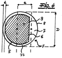
- the Fig. 4 shows bicomponent filaments with an eccentric core-sheath configuration, which are particularly preferred in the context of the invention.
- a cross section through an endless filament F with the preferred special core-sheath configuration is shown.
- the sheath 37 preferably has a constant thickness d in the filament cross section and in the exemplary embodiment over more than 50%, preferably over more than 55% of the filament circumference.
- the core 4 of the filaments F takes up more than 65% of the area of the filament cross-section of the filaments F.
- the core 4 - viewed in the filament cross section - is configured in the shape of a segment of a circle.
- this core 4 has an arcuate circumferential section 5 and a linear circumferential section 6 with respect to its circumference.
- the jacket 37 of the filaments F - viewed in the filament cross section - is designed in the shape of a segment of a circle outside the jacket area with the constant thickness d.
- This circular segment 7 of the jacket 37 has, as recommended and in the exemplary embodiment with respect to its circumference, an arcuate circumferential section 8 and a linear circumferential section 9.
- the thickness d or the mean thickness d of the jacket 37 in the range of its constant thickness is preferably 0.5% to 8%, in particular 2% to 10% of the filament diameter D.
- the thickness d of the jacket 37 may be in the range of its constant Thickness is 0.05 ⁇ m to 3 ⁇ m.
Abstract
Vorrichtung zur Herstellung eines Vliesstoffes, wobei zumindest eine Spinneinrichtung zum Erspinnen von Fasern vorhanden ist und wobei ein Ablageförderer vorgesehen ist, auf dem die Fasern zur Vliesbahn ablegbar sind. Es ist zumindest eine Heißluft-Vorverfestigungseinrichtung zur Heißluft-Vorverfestigung der Vliesbahn auf dem Ablageförderer vorgesehen. In Förderrichtung der Vliesbahn ist hinter dem Ablageförderer ein weiterer Förderer zur Aufnahme der vorverfestigten Vliesbahn angeordnet, wobei zumindest eine Endverfestigungseinrichtung zur Endverfestigung der Vliesbahn auf dem weiteren Förderer vorgesehen ist. Die Heißluft-Vorverfestigung der Vliesbahn ist auf dem Ablageförderer mit der Maßgabe durchführbar, dass die Vliesbahn vor der Übergabe an den weiteren Förderer eine Festigkeit in Maschinenrichtung (MD) von 0,6 bis 4 N/5 cm aufweist.Apparatus for producing a nonwoven fabric, wherein there is at least one spinning device for spinning fibers and wherein a depositing conveyor is provided on which the fibers can be deposited to form the nonwoven web. At least one hot air pre-consolidation device is provided for the hot air pre-consolidation of the nonwoven web on the delivery conveyor. In the conveying direction of the nonwoven web, another conveyor for receiving the pre-consolidated nonwoven web is arranged behind the depositing conveyor, at least one final consolidation device being provided for final consolidation of the nonwoven web on the further conveyor. The hot air pre-consolidation of the nonwoven web can be carried out on the delivery conveyor with the proviso that the nonwoven web has a strength in the machine direction (MD) of 0.6 to 4 N / 5 cm before it is transferred to the further conveyor.
Description
Die Erfindung betrifft eine Vorrichtung zur Herstellung eines Vliesstoffes mit zumindest einer Vliesbahn, wobei zumindest eine Spinneinrichtung bzw. zumindest ein Spinnbalken zum Erspinnen von Fasern vorhanden ist und wobei ein Ablageförderer - insbesondere ein Ablagesiebband - vorgesehen ist, auf dem die Fasern zur Vliesbahn ablegbar sind. Die Erfindung betrifft weiterhin auch ein Verfahren zur Herstellung eines entsprechenden Vliesstoffes. - Als Fasern werden im Rahmen der Erfindung insbesondere Fasern aus thermoplastischem Kunststoff eingesetzt und vorzugsweise Endlosfilamente aus thermoplastischem Kunststoff. Endlosfilamente unterscheiden sich aufgrund ihrer quasi endlosen Länge von Stapelfasern, die viel geringere Längen von beispielsweise 10 mm bis 60 mm aufweisen. Bei den im Rahmen der Erfindung eingesetzten Endlosfilamenten handelt es sich insbesondere um mit einer Spunbond-Vorrichtung bzw. mit einem Spunbond-Verfahren hergestellte Endlosfilamente, vorzugsweise aus thermoplastischem Kunststoff.The invention relates to a device for producing a nonwoven fabric with at least one nonwoven web, with at least one spinning device or at least one spinning beam for spinning fibers and with a depositing conveyor - in particular a depositing screen belt - being provided on which the fibers for the nonwoven web can be deposited. The invention also relates to a method for producing a corresponding nonwoven fabric. In the context of the invention, the fibers used are in particular fibers made of thermoplastic material and preferably continuous filaments made of thermoplastic material. Because of their quasi-endless length, continuous filaments differ from staple fibers, which have much shorter lengths of, for example, 10 mm to 60 mm. The continuous filaments used in the context of the invention are in particular continuous filaments, preferably made of thermoplastic material, produced with a spunbond device or with a spunbond process.
Vorrichtungen und Verfahren der eingangs genannten Art sind aus der Praxis in unterschiedlichen Ausführungsformen bekannt. So ist es bekannt, Endlosfilamente auf einem Ablagesiebband zur Vliesbahn abzulegen, diese einer Vorverfestigung zu unterziehen und anschließend eine Endverfestigung der Vliesbahn durchzuführen. Die Vorverfestigung kann beispielsweise mit Hilfe von Kompaktierwalzen erfolgen und die Endverfestigung insbesondere in einem Heißluftofen (through air bonding). Weiterhin ist es auch bekannt, dass im Ablagebereich der Fasern auf dem Ablagesiebband Luft bzw. Prozessluft durch das Ablagesiebband gesaugt wird. Die Vorverfestigung und die Endverfestigung finden bei vielen bekannten Vorrichtungen auf demselben Ablageförderer bzw. auf demselben Ablagesiebband statt. - Der Erfindung liegt die Erkenntnis zugrunde, dass diese Durchführung aller Verfestigungsmaßnahmen auf dem gleichen Ablageförderer nicht immer vorteilhaft ist.Devices and methods of the type mentioned are known from practice in different embodiments. For example, it is known to deposit endless filaments on a depositing screen belt for the nonwoven web, subject them to a pre-consolidation and then carry out a final consolidation of the nonwoven web. The pre-consolidation can take place, for example, with the aid of compacting rollers and the final consolidation in particular in a hot air oven (through air bonding). Furthermore, it is also known that in the storage area of the fibers on the storage screen belt, air or process air is sucked through the storage screen belt. In many known devices, the pre-consolidation and the final consolidation take place on the same deposit conveyor or on the same deposit screen belt. - The invention lies in the knowledge based on the fact that this implementation of all consolidation measures on the same deposit conveyor is not always advantageous.
Für bestimmte Anwendungen sind sogenannte High-Loft-Produkte sehr bevorzugt. Dabei handelt es sich um Vliesstoffe bzw. Spinnvliese mit einer relativ großen Dicke und einer hohen Weichheit. Die Herstellung dieser High-Loft-Produkte mit den gewünschten Eigenschaften ist nicht immer einfach, zumal die Vliesstoffe auch verfestigt werden müssen und die Verfestigungen Beeinträchtigungen der Dicke und/oder der Weichheit bedingen. Von daher besteht hier ein Zielkonflikt von einerseits hoher Weichheit und Dicke und andererseits ausreichender Festigkeit bzw. Abriebsfestigkeit der Vliesstoffe. Die bislang bekannten Vorrichtungen und Verfahren haben in dieser Hinsicht oftmals keine zufriedenstellenden Ergebnisse gebracht.So-called high-loft products are very preferred for certain applications. These are nonwovens or spunbonded fabrics with a relatively large thickness and high softness. The production of these high-loft products with the desired properties is not always easy, especially since the nonwovens also have to be consolidated and the consolidations cause impairments in thickness and / or softness. Therefore, there is a conflict of objectives of high softness and thickness on the one hand and sufficient strength or abrasion resistance of the nonwovens on the other. The devices and methods known up to now have often not produced satisfactory results in this regard.
Demgegenüber liegt der Erfindung das technische Problem zugrunde, eine Vorrichtung der eingangs genannten Art anzugeben, mit der eine vorteilhafte Vorverfestigung und auch eine optimale Endverfestigung von Vliesstoffen erzielt werden kann und mit der außerdem bei Bedarf auch ein Vliesstoff von hoher Dicke und hoher Weichheit problemlos hergestellt werden kann. Der Erfindung liegt weiterhin das technische Problem zugrunde, ein entsprechendes Verfahren zur Herstellung eines solchen Vliesstoffes anzugeben.In contrast, the invention is based on the technical problem of specifying a device of the type mentioned with which an advantageous pre-consolidation and also an optimal final consolidation of nonwovens can be achieved and with which, if necessary, a nonwoven of high thickness and high softness can also be easily produced can. The invention is also based on the technical problem of specifying a corresponding method for producing such a nonwoven fabric.
Zur Lösung dieses technischen Problems lehrt die Erfindung eine Vorrichtung zur Herstellung eines Vliesstoffes mit zumindest einer Vliesbahn, wobei zumindest eine Spinneinrichtung bzw. zumindest ein Spinnbalken zum Erspinnen von Fasern vorhanden ist, wobei ein Ablageförderer - insbesondere ein Ablagesiebband - vorgesehen ist, auf dem die Fasern zur Vliesbahn ablegbar sind,
wobei zumindest eine Heißluft-Vorverfestigungseinrichtung zur Heißluft-Vorverfestigung der Vliesbahn auf dem Ablageförderer bzw. auf dem Ablagesiebband vorgesehen ist,
wobei in Förderrichtung der Vliesbahn hinter dem Ablageförderer bzw. hinter dem Ablagesiebband ein weiterer Förderer - insbesondere in Form eines Förderbandes - zur Aufnahme der vorverfestigten Vliesbahn von dem Ablageförderer angeordnet ist, wobei zumindest eine Endverfestigungseinrichtung - insbesondere zumindest eine Heißluft-Endverfestigungseinrichtung - zur Endverfestigung bzw. zur Heißluft-Endverfestigung der Vliesbahn auf dem weiteren Förderer bzw. auf dem Förderband vorgesehen ist
und wobei die Heißluft-Vorverfestigung der Vliesbahn auf dem Ablageförderer bzw. auf dem Ablagesiebband mit der Maßgabe durchführbar ist, dass die Vliesbahn vor der Übergabe an den weiteren Förderer bzw. an das Förderband eine Festigkeit in Maschinenrichtung (MD) von 0,5 bis 5 N/5 cm, insbesondere von 0,7 bis 3,5 N/5 cm und vorzugsweise von 0,8 bis 3,5 N/5 cm aufweist. - Maschinenrichtung (MD) meint im Rahmen der Erfindung insbesondere die Förderrichtung des Ablageförderers bzw. die Förderrichtung der Vliesbahn
Der erfindungsgemäß hergestellte Vliesstoff kann lediglich eine Vliesbahn bzw. eine Vlieslage aufweisen oder er kann auch mehrere übereinander angeordnete Vliesbahnen bzw. Vlieslagen aufweisen, die zum Vlieslaminat kombiniert werden. Wenn mehrere Vliesbahnen übereinander angeordnet werden, ist zweckmäßigerweise jeder Vliesbahn eine Spinneinrichtung bzw. ein Spinnbalken zugeordnet. In der Regel entspricht die Anzahl der hintereinander angeordneten Spinneinrichtungen bzw. Spinnbalken der Anzahl der Vliesbahnen bzw. Vlieslagen, die übereinander zu dem Vlieslaminat kombiniert werden.To solve this technical problem, the invention teaches a device for producing a nonwoven fabric with at least one nonwoven web, with at least one spinning device or at least one spinning beam for spinning fibers, a depositing conveyor - in particular a depositing screen belt - being provided on which the fibers can be placed on the fleece web,
wherein at least one hot air pre-consolidation device is provided for the hot air pre-consolidation of the nonwoven web on the deposit conveyor or on the deposit screen belt,
wherein a further conveyor - in particular in the form of a conveyor belt - is arranged in the conveying direction of the nonwoven web behind the depositing conveyor or behind the depositing screen belt for receiving the pre-consolidated nonwoven web from the depositing conveyor, with at least one final consolidation device - in particular at least one hot air final consolidation device - for final consolidation or is provided for the final hot air consolidation of the nonwoven web on the further conveyor or on the conveyor belt
and wherein the hot air pre-consolidation of the nonwoven web on the deposit conveyor or on the deposit screen belt can be carried out with the proviso that the nonwoven web has a strength in the machine direction (MD) of 0.5 to 5 before being transferred to the further conveyor or to the conveyor belt N / 5 cm, in particular from 0.7 to 3.5 N / 5 cm and preferably from 0.8 to 3.5 N / 5 cm. - Machine direction (MD) in the context of the invention means in particular the conveying direction of the depositing conveyor or the conveying direction of the nonwoven web
The nonwoven fabric produced according to the invention can only have one nonwoven web or a nonwoven layer or it can also have several nonwoven webs or nonwoven layers arranged one above the other, which are combined to form the nonwoven laminate. If several nonwoven webs are arranged one above the other, it is expedient to assign a spinning device or a spinning beam to each nonwoven web. As a rule, the number of spinning devices or spinning bars arranged one behind the other corresponds to the number of fleece webs or fleece layers which are combined one above the other to form the fleece laminate.
Der Ablageförderer bzw. das Ablagesiebband ist insbesondere als endlos umlaufendes Ablagesiebband ausgebildet. Zweckmäßigerweise ist der Förderer bzw. das Förderband als endlos umlaufendes Förderband ausgeführt. Es liegt im Rahmen der Erfindung, dass der Ablageförderer bzw. das Ablagesiebband luftdurchlässig zum Durchsaugen von Prozessluft ausgebildet ist. Grundsätzlich liegt es auch im Rahmen der Erfindung, dass der weitere Förderer bzw. das Förderband luftdurchlässig ausgeführt sein kann. - Prinzipiell kann der weitere Förderer im Übrigen auch als Walze oder Trommel oder dergleichen ausgebildet sein.The deposit conveyor or the deposit screen belt is designed in particular as an endlessly revolving deposit screen belt. The conveyor or the conveyor belt is expediently designed as an endlessly revolving conveyor belt. It is within the scope of the invention that the depositing conveyor or the depositing screen belt is designed to be air-permeable for sucking through process air. In principle, it is also within the scope of the invention that the further conveyor or the conveyor belt can be made air-permeable. In principle, the further conveyor can also be designed as a roller or drum or the like.
Erfindungsgemäß werden für die Vorverfestigung der Vliesbahn einerseits und für die Endverfestigung der Vliesbahn andererseits separate Förderer eingesetzt, nämlich der Ablageförderer bzw. das Ablagesiebband für die Heißluft-Vorverfestigung und der weitere Förderer bzw. das Förderband für die Endverfestigung bzw. die Heißluft-Endverfestigung. Der Erfindung liegt insoweit die Erkenntnis zugrunde, dass diese Auftrennung der Förderer für die Vorverfestigung zum einen und für die Endverfestigung zum anderen für den herzustellenden Vliesstoff überraschenderweise besonders vorteilhaft ist und insbesondere auch zu Vorteilen bei der Verfahrensführung zur Herstellung des Vliesstoffes führt. Das gilt vor allem für Vliesstoffe mit geringeren Flächengewichten und/oder für die Herstellung von Vliesstoffen bei höheren Produktionsgeschwindigkeiten.According to the invention, separate conveyors are used for the pre-consolidation of the nonwoven web on the one hand and for the final consolidation of the nonwoven web on the other hand, namely the deposit conveyor or screen belt for hot air pre-consolidation and the further conveyor or conveyor belt for final consolidation or hot air final consolidation. The invention is based on the knowledge that this separation of the conveyors for the pre-consolidation on the one hand and for the final consolidation on the other hand is surprisingly particularly advantageous for the nonwoven fabric to be produced and in particular also leads to advantages in the process management for the production of the nonwoven fabric. This is especially true for nonwovens with a lower basis weight and / or for the production of nonwovens at higher production speeds.
Der Erfindung liegt unter anderem die Erkenntnis zugrunde, dass die erfindungsgemäße Vorrichtung und ein mit der erfindungsgemäßen Vorrichtung durchgeführtes Verfahren in energetischer Hinsicht besonders vorteilhaft sind. Bei den aus dem Stand der Technik bekannten Anlagen, bei denen die Vorverfestigung und die Endverfestigung auf demselben Ablagesiebband durchgeführt werden, stellen sich zwangsläufig relativ hohe Energieverluste ein. In der Heißluft-Endverfestigungseinrichtung wird der Vliesstoff bzw. das Siebband auf relativ hohe Temperaturen erwärmt. Das endlos umlaufende Ablagesiebband wird anschließend wieder durch den Ablagebereich für die Fasern geführt, in dem Prozessluft durch das Ablagesiebband gesaugt wird und dieses folglich relativ deutlich abgekühlt wird. Dieses abgekühlte Siebband muss anschließend wieder in energetisch aufwendiger Weise in der Endverfestigungseinrichtung aufgeheizt werden. Damit sind beachtliche Energieverluste verbunden, die mit höheren Produktionsgeschwindigkeiten - beispielsweise in Mehrbalken-Anlagen - noch weiter steigen. Diese werden im Rahmen der erfindungsgemäßen Lehre vorteilhaft vermieden.The invention is based, inter alia, on the knowledge that the device according to the invention and a method carried out with the device according to the invention are particularly advantageous in terms of energy. In the systems known from the prior art, in which the pre-consolidation and the final consolidation are carried out on the same screen belt there are inevitably relatively high energy losses. In the hot air final consolidation device, the nonwoven fabric or the screen belt is heated to relatively high temperatures. The endlessly revolving storage screen belt is then guided again through the storage area for the fibers, in which process air is sucked through the storage screen belt and this is consequently cooled down relatively significantly. This cooled sieve belt then has to be heated up again in the final consolidation device, which is expensive in terms of energy. This is associated with considerable energy losses, which increase even further at higher production speeds - for example in multi-beam systems. These are advantageously avoided in the context of the teaching according to the invention.
Die erfindungsgemäße Vorrichtung eignet sich auch besonders gut für die Herstellung von High-Loft-Produkten. Mit der Vorrichtung ist es möglich, einen optimalen Kompromiss zwischen ausreichender Dicke und hoher Weichheit des Vliesstoffes und zudem einer zufriedenstellenden Festigkeit des Vliesstoffes zu erreichen. Dabei liegt der Erfindung die Erkenntnis zugrunde, dass der Vliesstoff nach der Vorverfestigung eine Festigkeit in Maschinenrichtung (MD) in dem erfindungsgemäß beanspruchten Intervall haben sollte. Im Ergebnis können voluminöse und weiche Vliesstoffe mit einer optimalen Festigkeit erzielt werden.The device according to the invention is also particularly suitable for the production of high-loft products. With the device it is possible to achieve an optimal compromise between sufficient thickness and high softness of the nonwoven fabric and also a satisfactory strength of the nonwoven fabric. The invention is based on the knowledge that the nonwoven should have a strength in the machine direction (MD) in the interval claimed according to the invention after the pre-consolidation. As a result, voluminous and soft non-woven fabrics with an optimal strength can be obtained.
Besonders bewährt hat sich die erfindungsgemäße Lehre bzw. die erfindungsgemäße Vorrichtung bei Vlieslaminaten aus zumindest zwei Vliesbahnen bzw. aus mehr als zwei Vliesbahnen, wobei diese Vlieslaminate mit einer Zwei-Balken-Anlage oder mit einer Mehrbalken-Anlage hergestellt werden.The teaching according to the invention or the device according to the invention has proven particularly useful in nonwoven laminates made of at least two nonwoven webs or more than two nonwoven webs, these nonwoven laminates being produced with a two-bar system or with a multi-bar system.
Nach besonders bevorzugter Ausführungsform der Erfindung ist der Vliesstoff ein Vlieslaminat aus zumindest zwei Vliesbahnen, wobei zumindest zwei Spinneinrichtungen bzw. Spinnbalken zur Erzeugung der Fasern für diese Vliesbahnen vorgesehen sind,
wobei eine erste Spinneinrichtung bzw. ein erster Spinnbalken zum Erspinnen von ersten Fasern vorhanden ist, wobei die ersten Fasern auf dem Ablageförderer bzw. auf dem Ablagesiebband zu einer ersten Vliesbahn ablegbar sind,
wobei eine zweite Spinneinrichtung bzw. ein zweiter Spinnbalken zum Erspinnen von zweiten Fasern vorhanden ist, wobei der zweite Spinnbalken dem ersten Spinnbalken in Förderrichtung des Ablageförderers nachgeschaltet ist und wobei die zweiten Fasern auf dem Ablageförderer bzw. auf der ersten Vliesbahn zur zweiten Vliesbahn ablegbar sind,
wobei zwischen dem ersten und dem zweiten Spinnbalken zumindest eine Heißluft-Vorverfestigungseinrichtung als zumindest eine erste Heißluft-Vorverfestigungseinrichtung zur Heißluft-Vorverfestigung der ersten Vliesbahn vorgesehen ist,
wobei in Förderrichtung der Faserablage nach dem zweiten Spinnbalken zumindest eine zweite Heißluft-Vorverfestigungseinrichtung zur Heißluft-Vorverfestigung der zweiten Vliesbahn bzw. des Laminates aus erster und zweiter Vliesbahn angeordnet ist,
wobei das Laminat von dem Ablageförderer an den weiteren Förderer, insbesondere in Form des Förderbandes übergebbar ist bzw. übergeben wird, wobei das Laminat mit der Endverfestigungseinrichtung, insbesondere mit der Heißluft-Endverfestigungseinrichtung auf dem weiteren Förderer endverfestigt wird
und wobei die Heißluft-Vorverfestigung der ersten Vliesbahn bzw. des Laminates auf dem Ablageförderer mit der Maßgabe durchführbar ist, dass das Laminat vor der Übergabe an den weiteren Förderer eine Festigkeit in Maschinenrichtung (MD) von 0,5 bis 5 N/5 cm, insbesondere von 0,7 bis 3,5 N/5 cm und vorzugsweise von 0,8 bis 3,5 N/5 cm aufweist.According to a particularly preferred embodiment of the invention, the nonwoven fabric is a nonwoven laminate of at least two nonwoven webs, with at least two spinning devices or spinning beams are provided for producing the fibers for these fleece webs,
wherein a first spinning device or a first spinning beam is present for spinning first fibers, wherein the first fibers can be deposited on the deposit conveyor or on the deposit screen belt to form a first nonwoven web,
wherein a second spinning device or a second spinning beam is present for spinning second fibers, wherein the second spinning beam is connected downstream of the first spinning beam in the conveying direction of the deposit conveyor and wherein the second fibers can be deposited on the deposit conveyor or on the first nonwoven web to the second nonwoven web,
wherein between the first and the second spinning beam at least one hot air pre-consolidation device is provided as at least one first hot air pre-consolidation device for hot air pre-consolidation of the first nonwoven web,
wherein at least one second hot air pre-consolidation device for hot air pre-consolidation of the second nonwoven web or the laminate of the first and second nonwoven web is arranged in the conveying direction of the fiber deposit after the second spinning beam,
wherein the laminate can be or will be transferred from the deposit conveyor to the further conveyor, in particular in the form of the conveyor belt, the laminate being finally consolidated with the final consolidation device, in particular with the hot air final consolidation device on the further conveyor
and wherein the hot air pre-consolidation of the first nonwoven web or the laminate on the delivery conveyor can be carried out with the proviso that the laminate has a strength in the machine direction (MD) of 0.5 to 5 N / 5 cm before being transferred to the further conveyor, in particular from 0.7 to 3.5 N / 5 cm and preferably from 0.8 to 3.5 N / 5 cm.
Wenn im Rahmen der Erfindung zwei oder mehr Spinneinrichtungen bzw. Spinnbalken eingesetzt werden und zwei oder mehr Vliesbahnen für ein erfindungsgemäßes Vlieslaminat erzeugt werden, liegt es im Rahmen der Erfindung, dass jeder Spinneinrichtung bzw. jedem Spinnbalken zumindest eine Heißluft-Vorverfestigungseinrichtung zur Heißluft-Vorverfestigung der Vliesbahn bzw. des Vliesbahnaggregates nachgeschaltet ist. Weiterhin liegt es im Rahmen der Erfindung, dass die Ablage der Fasern für die einzelnen Vliesbahnen und die Heißluft-Vorverfestigungen auf ein und demselben Ablageförderer bzw. Ablagesiebband durchgeführt werden. Die Endverfestigung findet im Anschluss daran auf dem weiteren Förderer bzw. auf dem Förderband statt. - Grundsätzlich liegt es auch im Rahmen der Erfindung, dass bei Erzeugung lediglich einer Vliesbahn oder bei der Erzeugung mehrerer Vliesbahnen mit mehreren Spinnbalken zwischen dem Ablageförderer und dem weiteren Förderer zumindest ein Zwischenförderer bzw. zumindest ein Zwischenförderband zwischengeschaltet ist. In diesem Fall ist die erfindungsgemäße Lehre vorzugsweise so zu verstehen, dass die einzelne Vliesbahn bzw. das Vliesbahnaggregat vor der Übergabe auf den zumindest einen Zwischenförderer die Festigkeit in Maschinenrichtung (MD) in dem beanspruchten Intervall aufweist. Bei dem Zwischenförderer kann es sich im Übrigen auch um eine Walze bzw. Umlenkwalze, eine Rolle, eine Trommel oder dergleichen handeln.If two or more spinning devices or spinning beams are used within the scope of the invention and two or more nonwoven webs are produced for a nonwoven laminate according to the invention, it is within the scope of the invention that each spinning device or each spinning beam has at least one hot air pre-consolidation device for hot air pre-consolidation of the Nonwoven web or the nonwoven web aggregate is connected downstream. Furthermore, it is within the scope of the invention that the filing of the fibers for the individual nonwoven webs and the hot air pre-consolidations are carried out on one and the same filing conveyor or filing screen belt. The final consolidation then takes place on the further conveyor or on the conveyor belt. - Basically, it is also within the scope of the invention that when producing only one nonwoven web or when producing several nonwoven webs with several spinning beams between the deposit conveyor and the further conveyor at least one intermediate conveyor or at least one intermediate conveyor belt is interposed. In this case, the teaching according to the invention is preferably to be understood in such a way that the individual nonwoven web or the nonwoven web aggregate has the strength in the machine direction (MD) in the claimed interval before being transferred to the at least one intermediate conveyor. The intermediate conveyor can moreover also be a roller or deflection roller, a roller, a drum or the like.
Es liegt im Rahmen der Erfindung, dass zumindest eine Spinneinrichtung bzw. zumindest ein Spinnbalken der erfindungsgemäßen Vorrichtung bzw. die zumindest einer Spinneinrichtung bzw. zumindest einem Spinnbalken zugeordnete Vorrichtungskomponente der erfindungsgemäßen Vorrichtung als Spunbond-Vorrichtung zur Erzeugung einer Spunbond-Vliesbahn aus Endlosfilamenten ausgebildet ist. Gemäß einer Ausführungsform der Erfindung sind alle Spinneinrichtungen bzw. Spinnbalken und somit die entsprechenden Vorrichtungskomponenten jeweils als Spunbond-Vorrichtung zur Erzeugung von Spunbond-Vliesbahnen mit Endlosfilamenten ausgeführt.It is within the scope of the invention that at least one spinning device or at least one spinning beam of the device according to the invention or the device component of the device according to the invention assigned to at least one spinning device or at least one spinning beam is designed as a spunbond device for producing a spunbond nonwoven web from continuous filaments. According to one embodiment of the invention, all spinning devices or spinning beams and thus the corresponding device components are each designed as a spunbond device for producing spunbond nonwoven webs with continuous filaments.
Eine ganz besonders bevorzugte Ausführungsform der Erfindung ist dadurch gekennzeichnet, dass zumindest eine der Spinneinrichtungen bzw. zumindest einer der Spinnbalken zur Erzeugung von Bikomponentenfasern bzw. Multikomponentenfasern und insbesondere zur Erzeugung von Bikomponentenfilamenten bzw. Multikomponentenfilamenten eingerichtet ist. Gemäß einer empfohlenen Ausführungsform der Erfindung sind alle Spinneinrichtungen bzw. alle Spinnbalken der erfindungsgemäßen Vorrichtung zur Erzeugung von Bikomponentenfasern/Multikomponentenfasern, insbesondere von Bikomponentenfilamenten/Multikomponentenfilamenten eingerichtet. - Es liegt weiterhin im Rahmen der Erfindung, dass die Vorrichtung zur Herstellung zumindest eines Vliesstoffes bzw. zumindest einer Vliesbahn aus gekräuselten Fasern bzw. aus gekräuselten Endlosfilamenten ausgebildet ist. Vorzugsweise ist zumindest eine Spinneinrichtung bzw. zumindest ein Spinnbalken zur Erzeugung von gekräuselten Fasern bzw. zur Erzeugung von gekräuselten Endlosfilamenten eingerichtet. Bei Einsatz mehrerer Spinnbalken für die erfindungsgemäße Vorrichtung ist zumindest ein Spinnbalken oder sind zumindest zwei Spinnbalken oder sind alle Spinnbalken für die Erzeugung von gekräuselten Fasern bzw. von gekräuselten Endlosfilamenten eingerichtet.A particularly preferred embodiment of the invention is characterized in that at least one of the spinning devices or at least one of the spinning beams is set up to produce bicomponent fibers or multicomponent fibers and in particular to produce bicomponent filaments or multicomponent filaments. According to a recommended embodiment of the invention, all spinning devices or all spinning beams of the device according to the invention are set up for the production of bicomponent fibers / multicomponent fibers, in particular bicomponent filaments / multicomponent filaments. It is also within the scope of the invention that the device for producing at least one nonwoven fabric or at least one nonwoven web is formed from crimped fibers or from crimped continuous filaments. At least one spinning device or at least one spinning beam is preferably set up to produce crimped fibers or to produce crimped continuous filaments. When using several spinning beams for the device according to the invention, at least one spinning beam or at least two spinning beams or all spinning beams are set up for the production of crimped fibers or crimped continuous filaments.
Der Ausführungsform der erfindungsgemäßen Vorrichtung bzw. des erfindungsgemäßen Verfahrens für die Erzeugung mindestens einer Vliesbahn aus gekräuselten Fasern bzw. Endlosfilamenten kommt besondere Bedeutung zu. Auf diese Weise kann sehr einfach ein High-Loft-Vliesstoff erzeugt werden. Dabei liegt der Erfindung die Erkenntnis zugrunde, dass die vorteilhaften Eigenschaften eines solchen High-Loft-Produktes überraschenderweise aufgrund des Aufbaus der erfindungsgemäßen Vorrichtung bzw. aufgrund der Durchführung des erfindungsgemäßen Verfahrens beibehalten werden können und nichtsdestoweniger eine effektive Verfahrensführung mit einer ausreichenden Festigkeit der Vliesbahn bzw. der Vliesbahnen möglich ist. Zur Erzeugung von gekräuselten Fasern bzw. Endlosfilamenten können im Rahmen der Erfindung Fasern bzw. Endlosfilamente mit exzentrischer Kern-Mantel-Konfiguration oder mit Seite-an-Seite-Konfiguration eingesetzt werden. Dabei werden Fasern bzw. Endlosfilamente mit exzentrischer Kern-Mantel-Konfiguration bevorzugt. Diese letztgenannten Fasern haben sich für die erfindungsgemäße Vorrichtung bzw. für das erfindungsgemäße Verfahren besonders bewährt. Eine sehr bevorzugte Ausführungsform von im Rahmen der Erfindung eingesetzten Endlosfilamenten mit exzentrischer Kern-Mantel-Konfiguration wird weiter unten noch näher erläutert.The embodiment of the device according to the invention or of the method according to the invention for producing at least one nonwoven web from crimped fibers or continuous filaments is of particular importance. In this way, a high-loft nonwoven can be produced very easily. The invention is based on the knowledge that the advantageous properties of such a high-loft product can surprisingly be retained due to the structure of the device according to the invention or due to the implementation of the method according to the invention and nevertheless an effective process management with sufficient strength of the nonwoven web or the fleece webs is possible. In order to produce crimped fibers or continuous filaments, fibers or continuous filaments with an eccentric core-sheath configuration or with a side-by-side configuration can be used within the scope of the invention. Fibers or continuous filaments with an eccentric core-sheath configuration are preferred. These last-mentioned fibers have proven particularly useful for the device according to the invention and for the method according to the invention. A very preferred embodiment of continuous filaments with an eccentric core-sheath configuration used in the context of the invention is explained in more detail below.
Eine sehr zweckmäßige Ausgestaltung der Erfindung ist dadurch gekennzeichnet, dass für die mit zumindest einem Spinnbalken ersponnenen Fasern bzw. Filamente zumindest eine Kühlvorrichtung zur Kühlung der Fasern sowie zumindest eine an die Kühlvorrichtung anschließende Verstreckeinrichtung zur Verstreckung der Fasern vorgesehen ist. Vorteilhafterweise schließt an die Verstreckeinrichtung in Strömungsrichtung der Fasern/Filamente zumindest ein Diffusor an. Eine sehr empfohlene Ausführungsform der Erfindung ist dadurch gekennzeichnet, dass das Aggregat aus der Kühlvorrichtung und der Verstreckeinrichtung als geschlossenes Aggregat ausgebildet ist und dass in dieses Aggregat außer der Zufuhr von Kühlluft in der Kühlvorrichtung keine weitere Luft von außen zugeführt wird. Zweckmäßigerweise werden die den Diffusor verlassenden Fasern/Filamente unmittelbar auf dem Ablageförderer bzw. auf dem Ablagesiebband abgelegt.A very useful embodiment of the invention is characterized in that at least one cooling device for cooling the fibers and at least one stretching device adjoining the cooling device for stretching the fibers is provided for the fibers or filaments spun with at least one spinning beam. Advantageously, at least one diffuser adjoins the stretching device in the flow direction of the fibers / filaments. A highly recommended embodiment of the invention is characterized in that the unit from the cooling device and the stretching device is designed as a closed unit and that in this Aggregate other than the supply of cooling air in the cooling device no further air is supplied from the outside. The fibers / filaments leaving the diffuser are expediently deposited directly on the depositing conveyor or on the depositing screen belt.
Eine besonders bewährte Ausführungsform der Erfindung ist dadurch gekennzeichnet, dass die Heißluft-Vorverfestigungseinrichtung bzw. eine Heißluft-Vorverfestigungseinrichtung in Form zumindest eines Heißluftmessers und/oder in Form zumindest eines Heißluftofens ausgebildet ist. - Wenn zwei oder mehr Spinnbalken im Rahmen der erfindungsgemäßen Vorrichtung eingesetzt werden, ist vorzugsweise die erste Heißluft-Vorverfestigungseinrichtung zwischen dem ersten Spinnbalken und dem zweiten Spinnbalken in Form zumindest eines ersten Heißluftmessers und/oder in Form zumindest eines ersten Heißluftofens ausgebildet. Zweckmäßigerweise ist die zweite Heißluft-Vorverfestigungseinrichtung hinter dem zweiten Spinnbalken in Form zumindest eines zweiten Heißluftmessers und/oder in Form zumindest eines zweiten Heißluftofens ausgebildet.A particularly proven embodiment of the invention is characterized in that the hot air pre-consolidation device or a hot air pre-consolidation device is designed in the form of at least one hot air knife and / or in the form of at least one hot air oven. - If two or more spinning bars are used within the scope of the device according to the invention, the first hot air pre-consolidation device between the first spinning bar and the second spinning bar is preferably designed in the form of at least one first hot air knife and / or in the form of at least one first hot air oven. The second hot air pre-consolidation device is expediently designed in the form of at least one second hot air knife and / or in the form of at least one second hot air oven behind the second spinning beam.
Eine bewährte Ausführungsform der Erfindung ist dadurch gekennzeichnet, dass einer Vorrichtungskomponente mit einem Spinnbalken zunächst zumindest ein Heißluftmesser nachgeschaltet ist und dass diesem Heißluftmesser zumindest ein Heißluftofen nachgeschaltet ist. Dabei zeichnet sich eine Ausführungsform der Erfindung dadurch aus, dass dem Spinnbalken lediglich ein Heißluftmesser nachgeschaltet ist und dass diesem einen Heißluftmesser wiederum lediglich ein Heißluftofen nachgeschaltet ist.A proven embodiment of the invention is characterized in that a device component with a spinning beam is initially followed by at least one hot air knife and that at least one hot air oven is connected after this hot air knife. One embodiment of the invention is characterized in that only a hot air knife is connected downstream of the spinning beam and that this one hot air knife is in turn only connected by a hot air oven.
Bei Einsatz mehrerer Spinneinrichtungen bzw. Spinnbalken im Rahmen der erfindungsgemäßen Vorrichtung ist vorzugsweise in Förderrichtung der ersten Vliesbahn dem ersten Spinnbalken zunächst zumindest ein erstes Heißluftmesser nachgeschaltet und ist diesem ersten Heißluftmesser vor dem zweiten Spinnbalken zumindest ein erster Heißluftofen nachgeschaltet. Fernerhin ist zweckmäßigerweise in Förderrichtung des Laminates dem zweiten Spinnbalken zunächst zumindest ein zweites Heißluftmesser nachgeschaltet und diesem zweiten Heißluftmesser ist wiederum zumindest ein zweiter Heißluftofen nachgeschaltet. Es liegt im Rahmen der Erfindung, dass die Vliesbahn bzw. das Vliesbahnlaminat vor der Übergabe an den weiteren Förderer bzw. an das Förderband als letzte Heißluft-Vorverfestigungseinrichtung einen Heißluftofen verlassen hat.When using several spinning devices or spinning bars within the scope of the device according to the invention, there is preferably at least one first hot air knife on the first spinning bar in the conveying direction of the first nonwoven web downstream and at least one first hot air oven is connected downstream of this first hot air knife in front of the second spinning beam. Furthermore, in the conveying direction of the laminate, at least one second hot air knife is expediently first connected downstream of the second spinning beam and this second hot air knife is in turn connected by at least a second hot air oven. It is within the scope of the invention that the nonwoven web or the nonwoven web laminate has left a hot air oven as the last hot air pre-consolidation device before being transferred to the further conveyor or to the conveyor belt.
Grundsätzlich sind im Rahmen der Erfindung auch andere Kombinationen von Heißluft-Vorverfestigungseinrichtungen möglich. So kann einem Spinnbalken oder bei einer Zwei-Balken-Anlage oder Mehrbalken-Anlage zumindest einem Spinnbalken auch lediglich ein Heißluftmesser als Heißluft-Vorverfestigungseinrichtung nachgeschaltet sein. Gemäß einer Ausführungsform ist einem ersten Spinnbalken ein Heißluftmesser nachgeschaltet und diesem Heißluftmesser ist wiederum ein Heißluftofen zur Vorverfestigung nachgeschaltet. Dem zweiten Balken ist bei dieser Ausführungsform lediglich ein Heißluftmesser als Heißluft-Vorverfestigungseinrichtung nachgeschaltet. Eine andere Ausführungsform ist dadurch gekennzeichnet, dass dem ersten Spinnbalken lediglich ein Heißluftmesser als Heißluft-Vorverfestigungseinrichtung nachgeschaltet ist und dass dem zweiten Spinnbalken ein Heißluftmesser nachgeschaltet ist und diesem Heißluftmesser wiederum ein Heißluftofen als Heißluft-Vorverfestigungseinrichtung nachgeschaltet ist. Nach einer anderen Ausführungsvariante könnte hinter jedem Spinnbalken auch lediglich ein Heißluftofen als Heißluft-Vorverfestigungseinrichtung angeordnet sein. Insoweit gibt es im Rahmen der Erfindung verschiedene Varianten für Kombinationen von Heißluft-Vorverfestigungseinrichtungen.In principle, other combinations of hot air pre-consolidation devices are also possible within the scope of the invention. Thus, a spinning beam or, in the case of a two-beam system or multi-beam system, at least one spinning beam can also be followed by just a hot air knife as a hot air pre-consolidation device. According to one embodiment, a hot air knife is connected downstream of a first spinning beam and this hot air knife is, in turn, followed by a hot air oven for pre-consolidation. In this embodiment, only a hot air knife is connected downstream of the second bar as a hot air pre-consolidation device. Another embodiment is characterized in that only a hot air knife is connected downstream of the first spinning beam as a hot air pre-consolidation device and that the second spinning beam is followed by a hot air knife and this hot air knife is in turn followed by a hot air oven as a hot air pre-consolidation device. According to another embodiment variant, only a hot air oven could be arranged as a hot air pre-consolidation device behind each spinning beam. In this respect, there are various variants for combinations of hot air pre-consolidation devices within the scope of the invention.
Eine empfohlene Ausführungsform der Erfindung ist dadurch gekennzeichnet, dass ein Heißluftmesser die Vliesbahn bzw. das Laminat mit Heißluft über einen Breitenbereich in Maschinenrichtung (MD) von 15 mm bis 300 mm, insbesondere von 30 mm bis 250 mm, vorzugsweise von 40 mm bis 200 mm und bevorzugt von 40 mm bis 150 mm beaufschlagt. Zweckmäßigerweise beträgt der Abstand der zumindest einen Heißluftdüse des Heißluftmessers zur Oberfläche des Ablageförderers bzw. des Ablagesiebbandes 2 mm bis 200 mm, insbesondere 3 mm bis 100 mm. Zweckmäßigerweise gelten die vorstehend genannten Breitenbereiche und Abstandsbereiche bei einer Mehrbalken-Anlage für jedes zur Heißluft-Vorverfestigungseinrichtung eingesetzte Heißluftmesser.A recommended embodiment of the invention is characterized in that a hot air knife removes the fleece web or the laminate with hot air over a width range in the machine direction (MD) of 15 mm to 300 mm, in particular from 30 mm to 250 mm, preferably from 40 mm to 200 mm and preferably applied from 40 mm to 150 mm. The distance between the at least one hot air nozzle of the hot air knife and the surface of the depositing conveyor or the depositing screen belt is expediently 2 mm to 200 mm, in particular 3 mm to 100 mm. The width ranges and spacing ranges mentioned above expediently apply in the case of a multi-beam system for each hot air knife used for the hot air pre-consolidation device.
Weiterhin ist eine bewährte Ausführungsform der Erfindung dadurch gekennzeichnet, dass ein Heißluftofen die Vliesbahn bzw. das Laminat über einen Breitenbereich in Maschinenrichtung (MD) von 280 mm bis 2.000 mm, insbesondere von 290 mm bis 1.800 mm und vorzugsweise von 300 mm bis 1.500 mm mit Heißluft beaufschlagt. Empfohlenermaßen weisen die Heißluftaustrittsöffnungen des Heißluftofens zur Oberfläche des Ablageförders bzw. des Ablagesiebbandes einen Abstand von 12 mm bis 200 mm, insbesondere von 20 mm bis 150 mm und bevorzugt von 25 mm bis 120 mm auf. Zweckmäßigerweise gelten die vorgestehend genannten Breitenbereiche und/oder Abstandsbereiche bei einer Mehrbalken-Anlage für jeden zur Heißluft-Vorverfestigung eingesetzten Heißluftofen.Furthermore, a proven embodiment of the invention is characterized in that a hot-air oven with the nonwoven web or the laminate over a width range in the machine direction (MD) from 280 mm to 2,000 mm, in particular from 290 mm to 1,800 mm and preferably from 300 mm to 1,500 mm Hot air applied. The hot air outlet openings of the hot air oven are recommended to have a distance of 12 mm to 200 mm, in particular from 20 mm to 150 mm and preferably from 25 mm to 120 mm, to the surface of the deposit conveyor or the deposit screen belt. The width ranges and / or spacing ranges mentioned above expediently apply in the case of a multi-beam system for each hot air oven used for hot air pre-consolidation.
Es liegt im Rahmen der Erfindung, dass nach einem Heißluftmesser oder nach jedem Heißluftmesser und/oder dass nach einem Heißluftofen oder nach jedem Heißluftofen ein Kühlfeld angeordnet ist, in dem die Vliesbahn durch Kühlung stabilisiert wird. Zweckmäßigerweise ist ein solches Kühlfeld beispielsweise 400 mm bis 600 mm lang und wird z. B. von Kühlluft einer Geschwindigkeit von 1 bis 2 m/s durchströmt. Dadurch wird sowohl die Vliesbahn als auch der Ablageförderer gekühlt.It is within the scope of the invention that after a hot air knife or after each hot air knife and / or that after a hot air oven or after each hot air oven there is a cooling field in which the nonwoven web is stabilized by cooling. Appropriately, such a cooling field is for example 400 mm to 600 mm long and is z. B. of cooling air at a speed of 1 to 2 m / s flows through. This cools both the nonwoven web and the deposit conveyor.
Eine besonders bevorzugte Ausführungsform, der im Rahmen der Erfindung spezielle Bedeutung zukommt, ist dadurch gekennzeichnet, dass die Temperatur der Oberfläche des weiteren Förderers bzw. des Förderbandes in Förderrichtung vor der Heißluft-Endverfestigungseinrichtung höher ist als die Temperatur der Oberfläche des Ablageförderers bzw. des Ablagesiebbandes im Übergabebereich der Vliesbahn bzw. des Laminates an den weiteren Förderer bzw. an das Förderband. Wenn nach einer Ausführungsvariante der Erfindung zwischen dem Ablageförderer und dem weiteren Förderer zumindest ein Zwischenförderer angeordnet ist, meint diese Ausführungsform insbesondere, dass die Temperatur der Oberfläche des weiteren Förderers, insbesondere des Förderbandes in Förderrichtung vor der Heißluft-Endverfestigungseinrichtung höher ist als die Temperatur der Oberfläche des Ablageförderers bzw. Ablagesiebbandes im Übergabebereich der Vliesbahn bzw. des Laminates an den Zwischenförderer und/oder höher ist als die Temperatur der Oberfläche des Zwischenförderers. Zweckmäßigerweise ist bei diesen Ausführungsformen die Oberflächentemperatur des weiteren Förderers bzw. des Förderbandes um mindestens 5 °C, vorzugsweise um mindestens 10 °C und bevorzugt um mindestens 15 °C sowie sehr bevorzugt um mindestens 20 °C höher als die genannte Oberflächentemperatur des Ablageförderers und/oder des Zwischenförderers. - Wenn im Rahmen der Erfindung ein Zwischenförderer eingesetzt wird, der lediglich Transportfunktion hat, ist zweckmäßigerweise die Oberflächentemperatur dieses Zwischenförderers geringer als die Oberflächentemperatur des weiteren Förderers und die Oberflächentemperatur des Zwischenförderers ist bevorzugt auch geringer als die Temperatur der Vliesbahn bzw. des Laminates beim Einlauf auf den Zwischenförderer.A particularly preferred embodiment, which is of particular importance in the context of the invention, is characterized in that the temperature of the surface of the further conveyor or the conveyor belt in the conveying direction in front of the hot air final consolidation device is higher than the temperature of the surface of the deposit conveyor or the depositing screen belt in the transfer area of the fleece web or the laminate to the further conveyor or to the conveyor belt. If, according to one embodiment of the invention, at least one intermediate conveyor is arranged between the deposit conveyor and the further conveyor, this embodiment means in particular that the temperature of the surface of the further conveyor, in particular the conveyor belt in the conveying direction in front of the hot air final consolidation device, is higher than the temperature of the surface of the deposit conveyor or depositing screen belt in the transfer area of the nonwoven web or the laminate to the intermediate conveyor and / or is higher than the temperature of the surface of the intermediate conveyor. In these embodiments, the surface temperature of the further conveyor or the conveyor belt is expediently higher by at least 5 ° C, preferably by at least 10 ° C and preferably by at least 15 ° C and very preferably by at least 20 ° C higher than the specified surface temperature of the depositing conveyor and / or the intermediate conveyor. - If, within the scope of the invention, an intermediate conveyor is used which only has a transport function, the surface temperature of this intermediate conveyor is expediently lower than the surface temperature of the further conveyor and the surface temperature of the intermediate conveyor is preferably also lower than the temperature of the nonwoven web or the laminate at the inlet the intermediate conveyor.
Zur Lösung des technischen Problems lehrt die Erfindung weiterhin ein Verfahren zur Herstellung eines Vliesstoffes mit zumindest einer Vliesbahn, wobei Fasern ersponnen werden und auf einem Ablageförderer, insbesondere auf einem Ablagesiebband zu der Vliesbahn abgelegt werden,
wobei die Vliesbahn auf dem Ablageförderer mit Heißluft vorverfestigt wird und wobei die Vliesbahn von dem Ablageförderer bzw. von dem Ablagesiebband an einen weiteren Förderer bzw. an ein Förderband übergeben wird
und wobei die Heißluft-Vorverfestigung mit der Maßgabe durchgeführt wird, dass die Vliesbahn vor der Übergabe an den weiteren Förderer eine Festigkeit in Maschinenrichtung (MD) von 0,5 bis 5 N/5 cm, insbesondere von 0,7 bis 3,5 N/5 cm und vorzugsweise von 0,8 bis 3,5 N/5 cm aufweist.To solve the technical problem, the invention also teaches a method for producing a nonwoven fabric with at least one nonwoven web, wherein fibers are spun and deposited on a deposit conveyor, in particular on a depositing screen belt, to the nonwoven web,
wherein the nonwoven web is pre-consolidated on the deposit conveyor with hot air and wherein the nonwoven web is transferred from the deposit conveyor or from the deposit screen belt to a further conveyor or to a conveyor belt
and wherein the hot air pre-consolidation is carried out with the proviso that the nonwoven web has a strength in the machine direction (MD) of 0.5 to 5 N / 5 cm, in particular 0.7 to 3.5 N, before it is transferred to the further conveyor / 5 cm and preferably from 0.8 to 3.5 N / 5 cm.
Eine besonders bevorzugte Ausführungsform des erfindungsgemäßen Verfahrens ist dadurch gekennzeichnet, dass ein Vlieslaminat aus zumindest zwei Vliesbahnen erzeugt wird, wobei insbesondere zumindest eine Vliesbahn gekräuselte Fasern aufweist, wobei erste Fasern ersponnen werden und auf einem Ablageförderer, insbesondere auf einem Ablagesiebband zu einer ersten Vliesbahn abgelegt werden,
wobei zweite Fasern ersponnen werden und wobei diese zweiten Fasern auf der auf dem Ablageförderer transportierten ersten Vliesbahn zur zweiten Vliesbahn bzw. zum Laminat aus den beiden Vliesbahnen abgelegt werden,
wobei nach der Ablage der ersten Fasern und vor der Ablage der zweiten Fasern die erste Vliesbahn mit Heißluft vorverfestigt wird, wobei nach der Ablage der zweiten Fasern die zweite Vliesbahn bzw. das Laminat aus der ersten Vliesbahn und der zweiten Vliesbahn mit Heißluft vorverfestigt wird,
wobei das Laminat von dem Ablageförderer bzw. von dem Ablagesiebband an den weiteren Förderer bzw. an das Förderband übergeben wird und wobei die Heißluft-Vorverfestigungen mit der Maßgabe durchgeführt werden, dass das Laminat vor der Übergabe an den weiteren Förderer eine Festigkeit in Maschinenrichtung (MD) von 0,5 bis 5 N/5 cm, insbesondere von 0,7 bis 3,5 N/5 cm und vorzugsweise von 0,8 bis 3,5 N/5 cm aufweist.A particularly preferred embodiment of the method according to the invention is characterized in that a nonwoven laminate is produced from at least two nonwoven webs, in particular at least one nonwoven web having crimped fibers, the first fibers being spun and deposited on a deposit conveyor, in particular on a depositing screen belt, to form a first nonwoven web ,
wherein second fibers are spun and these second fibers are deposited on the first nonwoven web transported on the delivery conveyor to the second nonwoven web or to the laminate of the two nonwoven webs,
wherein after the first fibers have been deposited and before the second fibers are deposited, the first nonwoven web is pre-consolidated with hot air, wherein after the second fibers have been deposited the second nonwoven web or the laminate of the first nonwoven web and the second nonwoven web is pre-consolidated with hot air,
wherein the laminate is transferred from the deposit conveyor or from the deposit screen belt to the further conveyor or to the conveyor belt, and the hot air pre-consolidation is carried out with the proviso that the laminate has a strength in the machine direction (MD ) from 0.5 to 5 N / 5 cm, in particular from 0.7 to 3.5 N / 5 cm and preferably from 0.8 to 3.5 N / 5 cm.
Eine besonders bewährte Ausführungsform des erfindungsgemäßen Verfahrens zeichnet sich dadurch aus, dass die Fasern - insbesondere die Fasern des ersten Spinnbalkens und/oder die Fasern des zweiten Spinnbalkens - als Spunbond-Filamente bzw. Endlosfilamente ersponnen werden, insbesondere als Bikomponentenfilamente bzw. Multikomponentenfilamente ersponnen werden und vorzugsweise als gekräuselte Filamente abgelegt werden - insbesondere zur ersten Vliesbahn und/oder zur zweiten Vliesbahn - abgelegt werden. Gemäß besonders bevorzugter Ausführungsform der Erfindung werden die Fasern - insbesondere die Fasern des ersten Spinnbalkens und/oder die Fasern des zweiten Spinnbalkens - als Bikomponentenfilamente bzw. Multikomponentenfilamente mit exzentrischer Kern-Mantel-Konfiguration ersponnen.A particularly proven embodiment of the method according to the invention is characterized in that the fibers - in particular the fibers of the first spinning beam and / or the fibers of the second spinning beam - are spun as spunbond filaments or continuous filaments, in particular as bicomponent filaments or multicomponent filaments and are preferably deposited as crimped filaments - in particular to the first nonwoven web and / or to the second nonwoven web - are deposited. According to a particularly preferred embodiment of the invention, the fibers - in particular the fibers of the first spinning beam and / or the fibers of the second spinning beam - are spun as bicomponent filaments or multicomponent filaments with an eccentric core-sheath configuration.
Besonders bewährt haben sich im Rahmen der Erfindung Bikomponentenfilamente bzw. Multikomponentenfilamente mit exzentrischer Kern-Mantel-Konfiguration, bei denen der Mantel im Filamentquerschnitt über zumindest 20 %, insbesondere über zumindest 25 %, vorzugsweise über zumindest 30 %, bevorzugt über zumindest 35 % und sehr bevorzugt über zumindest 40 % sowie besonders bevorzugt über zumindest 45 % des Filamentumfanges eine konstante Dicke d bzw. eine im Wesentlichen konstante Dicke d aufweist. Sehr bevorzugt ist im Rahmen der Erfindung, dass der Mantel der Filamente über zumindest 50 %, vorzugsweise über zumindest 55 % und bevorzugt über zumindest 60 % des Filamentumfanges die konstante Dicke d bzw. die im Wesentlichen konstante Dicke d aufweist. Zweckmäßigerweise nimmt bei diesen Filamenten der Kern mehr als 50 %, insbesondere mehr als 55 %, vorzugsweise mehr als 60 %, bevorzugt mehr als 65 % der Fläche des Filamentquerschnittes der Filamente ein. Empfohlenermaßen ist der Kern dieser Filamente im Filamentquerschnitt gesehen kreissegmentförmig ausgebildet und weist bezüglich seines Umfanges einen kreisbogenförmigen bzw. einen im Wesentlichen kreisbogenförmigen Umfangsabschnitt auf sowie einen linearen bzw. im Wesentlichen linearen Umfangsabschnitt. Fernerhin ist bei diesen Filamenten bevorzugt, dass der Mantel der Filamente - im Filamentquerschnitt gesehen - außerhalb des Mantelbereiches mit der konstanten Dicke d kreissegmentförmig ausgebildet ist, wobei dieses Kreissegment bezüglich seines Umfanges einen kreisbogenförmigen bzw. im Wesentlichen kreisbogenförmigen Umfangsabschnitt aufweist sowie einen linearen bzw. im Wesentlichen linearen Umfangsabschnitt. Gemäß sehr empfohlener Ausführungsform beträgt die Dicke des Mantels dieser bevorzugten Filamente im Bereich der konstanten bzw. im Wesentlichen konstanten Dicke d des Mantels weniger als 10 %, insbesondere weniger als 8 % und vorzugsweise weniger als 7 % des Filamentdurchmessers D bzw. des größten Filamentdurchmessers D. Es liegt fernerhin im Rahmen der Erfindung, dass bei diesen bevorzugten Filamenten in Bezug auf den Filamentquerschnitt der Abstand a des Flächenschwerpunktes des Kerns von dem Flächenschwerpunkt des Mantels 5 % bis 45 %, insbesondere 6 % bis 40 % und vorzugsweise 6 % bis 36 % des Filamentdurchmessers D bzw. des größten Filamentdurchmessers D beträgt.Bicomponent filaments or multicomponent filaments with an eccentric core-sheath configuration, in which the sheath in the filament cross-section exceeds at least 20%, in particular over at least 25%, preferably over at least 30%, preferably over at least 35% and very much, have proven particularly useful in the context of the invention preferably has a constant thickness d or an essentially constant thickness d over at least 40% and particularly preferably over at least 45% of the filament circumference. It is very preferred in the context of the invention that the sheath of the filaments over has the constant thickness d or the essentially constant thickness d at least 50%, preferably over at least 55% and preferably over at least 60% of the filament circumference. In the case of these filaments, the core expediently takes up more than 50%, in particular more than 55%, preferably more than 60%, preferably more than 65% of the area of the filament cross-section of the filaments. It is recommended that the core of these filaments is formed in the shape of a segment of a circle when viewed in the filament cross-section and, with regard to its circumference, has an arcuate or an essentially arcuate circumferential section and a linear or essentially linear circumferential section. Furthermore, it is preferred with these filaments that the sheath of the filaments - seen in the filament cross section - is formed in the shape of a segment of a circle outside the sheath area with the constant thickness d, this segment of a circle having an arcuate or essentially arcuate circumferential section with respect to its circumference and a linear or in Essentially linear circumferential section. According to a highly recommended embodiment, the thickness of the sheath of these preferred filaments in the region of the constant or substantially constant thickness d of the sheath is less than 10%, in particular less than 8% and preferably less than 7% of the filament diameter D or the largest filament diameter D. It is also within the scope of the invention that with these preferred filaments, in relation to the filament cross-section, the distance a of the centroid of the core from the centroid of the jacket is 5% to 45%, in particular 6% to 40% and preferably 6% to 36% of the filament diameter D or the largest filament diameter D is.
Eine besonders empfohlene Ausführungsform der Erfindung ist dadurch gekennzeichnet, dass die erfindungsgemäß erzeugten Fasern bzw. Filamente aus zumindest einem Polyolefin bestehen bzw. im Wesentlichen bestehen. Wenn Bikomponentenfilamente bzw. Multikomponentenfilamente im Rahmen der Erfindung erzeugt werden, handelt es sich vorzugsweise um Bikomponentenfilamente bzw. Multikomponentenfilamente, bei denen zumindest eine Komponente oder beide bzw. alle Komponenten aus zumindest einem Polyolefin bzw. im Wesentlichen aus zumindest einem Polyolefin bestehen. Bei der Erzeugung von Filamenten mit exzentrischer Kern-Mantel-Konfiguration besteht vorzugsweise zumindest der Mantel aus zumindest einem Polyolefin bzw. im Wesentlichen aus zumindest einem Polyolefin. Nach einer sehr bewährten Ausführungsform besteht der Mantel aus Polyethylen bzw. im Wesentlichen aus Polyethylen und besteht bevorzugt der Kern aus Polypropylen bzw. im Wesentlichen aus Polypropylen. Gemäß einer anderen empfohlenen Ausführungsform besteht der Kern aus zumindest einem Polyester bzw. im Wesentlichen aus zumindest einem Polyester und besteht der Mantel aus zumindest einem Polyolefin bzw. im Wesentlichen aus zumindest einem Polyolefin. Als Polyester wird im Rahmen der Erfindung bevorzugt Polyethylenterephthalat (PET) eingesetzt. Bei einer bevorzugten Ausführungsvariante besteht der Kern aus PET bzw. im Wesentlichen aus PET und besteht der Mantel aus Polyethylen bzw. im Wesentlichen aus Polyethylen. Eine weitere Ausführungsform ist dadurch gekennzeichnet, dass der Kern aus zumindest einem Polyester besteht bzw. im Wesentlichen besteht und dass der Mantel aus zumindest einem Copolyester besteht bzw. im Wesentlichen besteht. Es liegt im Rahmen der Erfindung, dass die Kunststoffkomponente des Mantels einen geringeren Schmelzpunkt aufweist als die Kunststoffkomponente des Kerns. Im Rahmen der Erfindung haben sich Fasern bzw. Filamente aus den oben genannten Kunststoffen ganz besonders bewährt. Insbesondere haben sich Bikomponentenfilamente bzw. Multikomponentenfilamente mit exzentrischer Kern-Mantel-Konfiguration bewährt, deren Mantel aus Polyethylen bzw. im Wesentlichen aus Polyethylen besteht und deren Kern aus Polypropylen bzw. im Wesentlichen aus Polypropylen besteht.A particularly recommended embodiment of the invention is characterized in that the fibers or filaments produced according to the invention consist of or essentially consist of at least one polyolefin. If bicomponent filaments or multicomponent filaments are produced within the scope of the invention, they are preferably bicomponent filaments or multicomponent filaments in which at least one component or both or all components consist of at least one polyolefin or essentially of at least one polyolefin. When filaments with an eccentric core-sheath configuration are produced, at least the sheath preferably consists of at least one polyolefin or essentially of at least one polyolefin. According to a well-proven embodiment, the jacket consists of polyethylene or essentially of polyethylene and the core preferably consists of polypropylene or essentially of polypropylene. According to another recommended embodiment, the core consists of at least one polyester or essentially of at least one polyester and the jacket consists of at least one polyolefin or essentially of at least one polyolefin. Polyethylene terephthalate (PET) is preferably used as the polyester in the context of the invention. In a preferred embodiment variant, the core consists of PET or essentially of PET and the jacket consists of polyethylene or essentially of polyethylene. Another embodiment is characterized in that the core consists or substantially consists of at least one polyester and that the jacket consists or substantially consists of at least one copolyester. It is within the scope of the invention that the plastic component of the jacket has a lower melting point than the plastic component of the core. In the context of the invention, fibers or filaments made from the above-mentioned plastics have proven particularly useful. In particular, bicomponent filaments or multicomponent filaments with an eccentric core-sheath configuration have proven their sheath from Polyethylene or consists essentially of polyethylene and whose core consists of polypropylene or essentially of polypropylene.
Eine sehr bewährte Ausführungsform der Erfindung zeichnet sich dadurch aus, dass die Komponenten der Filamente bzw. der Kern und/oder der Mantel der Filamente mit exzentrischer Kern-Mantel-Konfiguration aus zumindest einem Polymer aus der Gruppe "Polyolefin, Polyolefin-Copolymer, insbesondere Polyethylen, Polypropylen, Polyethylen-Copolymer, Polypropylen-Copolymer; Polyester, Polyester-Copolymer, insbesondere Polyethylenterephthalat (PET), PET-Copolymer, Polybutylenterephthalat (PBT), PBT-Copolymer, Polylactid (PLA), PLA-Copolymer" besteht/bestehen bzw. im Wesentlichen besteht/bestehen. Es liegt auch im Rahmen der Erfindung, dass für eine Komponente bzw. für den Kern und/oder den Mantel Mischungen bzw. Blends der vorgenannten Polymere eingesetzt werden können. Weiterhin liegt es im Rahmen der Erfindung, dass bei Endlosfilamenten mit exzentrischer Kern-Mantel-Konfiguration der Kunststoff im Mantel eine niedrigere Schmelztemperatur aufweist als der Kunststoff im Kern.A very well-proven embodiment of the invention is characterized in that the components of the filaments or the core and / or the sheath of the filaments with an eccentric core-sheath configuration consists of at least one polymer from the group “polyolefin, polyolefin copolymer, in particular polyethylene , Polypropylene, polyethylene copolymer, polypropylene copolymer; polyester, polyester copolymer, in particular polyethylene terephthalate (PET), PET copolymer, polybutylene terephthalate (PBT), PBT copolymer, polylactide (PLA), PLA copolymer "consists or essentially exists / exist. It is also within the scope of the invention that mixtures or blends of the aforementioned polymers can be used for a component or for the core and / or the shell. Furthermore, it is within the scope of the invention that, in the case of continuous filaments with an eccentric core-sheath configuration, the plastic in the sheath has a lower melting temperature than the plastic in the core.
Vorzugsweise findet im Falle der Erzeugung eines Vliesstoffes bzw. eines einlagigen Vliesstoffproduktes die Heißluft-Vorverfestigung der Vliesbahn bei einer Heißlufttemperatur von 80 °C bis 200 °C, insbesondere von 100°C bis 175 °C, vorzugsweise von 110 °C bis 150 °C sowie sehr bevorzugt von 115 °C bis 140 °C statt. Es empfiehlt sich weiterhin, dass die Heißluft bei der Heißluft-Vorverfestigung mit einem Heißluftmesser eine Geschwindigkeit von 1,9 bis 6 m/s, insbesondere von 2 bis 5 m/s und vorzugsweise von 2,2 bis 4,5 m/s aufweist.In the case of the production of a nonwoven fabric or a single-layer nonwoven product, the hot air pre-consolidation of the nonwoven web takes place at a hot air temperature of 80 ° C to 200 ° C, in particular 100 ° C to 175 ° C, preferably 110 ° C to 150 ° C and very preferably from 115 ° C to 140 ° C instead. It is also recommended that the hot air has a speed of 1.9 to 6 m / s, in particular from 2 to 5 m / s and preferably from 2.2 to 4.5 m / s, during the hot air pre-consolidation with a hot air knife .
Eine besonders empfohlene Ausführungsform des erfindungsgemäßen Verfahrens ist dadurch gekennzeichnet, dass zumindest eine erzeugte Vliesbahn, insbesondere die erste Vliesbahn und/oder das Laminat aus der ersten Vliesbahn und der zweiten Vliesbahn zunächst mittels eines Heißluftmessers und ausschließlich durch einen Heißluftofen mit Heißluft vorverfestigt wird. Dabei findet die Heißluft-Vorverfestigung durch das Heißluftmesser jeweils bei einer Heißlufttemperatur von 80 °C bis 200 °C, insbesondere von 100 °C bis 180 °C und vorzugsweise von 120 °C bis 170 °C sowie sehr bevorzugt von 120 °C bis 160 °C statt. Es empfiehlt sich weiterhin, dass die Heißluft bei der Heißluftvor-Verfestigung mit einem Heißluftmesser eine Geschwindigkeit von 1,9 bis 6 m/s, insbesondere von 2 bis 5,5 m/s und vorzugsweise von 2,2 bis 4,5 m/s aufweist.A particularly recommended embodiment of the method according to the invention is characterized in that at least one generated Nonwoven web, in particular the first nonwoven web and / or the laminate of the first nonwoven web and the second nonwoven web is initially pre-consolidated with hot air by means of a hot air knife and exclusively by a hot air oven. The hot air pre-consolidation by the hot air knife takes place at a hot air temperature of 80 ° C to 200 ° C, in particular from 100 ° C to 180 ° C and preferably from 120 ° C to 170 ° C and very preferably from 120 ° C to 160 ° C instead. It is also recommended that the hot air during the hot air pre-consolidation with a hot air knife at a speed of 1.9 to 6 m / s, in particular from 2 to 5.5 m / s and preferably from 2.2 to 4.5 m / s has.
Wenn die Heißluft-Vorverfestigung einer Vliesbahn bzw. eines Vliesstofflaminates nach einer Ausführungsform mit lediglich einem Vorverfestigungsaggregat, insbesondere mit lediglich einem Heißluftmesser stattfindet, so wird die Heißlufttemperatur in einem Bereich von 80 °C bis 250 °C, insbesondere von 110 °C bis 200 °C und vorzugweise von 120 °C bis 190 °C sowie sehr bevorzugt von 130 °C bis 180 °C durchgeführt. Es empfiehlt sich weiterhin, dass die Heißluft bei der Heißluft-Vorverfestigung mit einem Heißluftmesser eine Geschwindigkeit von 1,9 bis 8 m/s, insbesondere von 2 bis 5,5 m/s und vorzugsweise von 2,2 bis 5,5 m/s aufweist.If the hot air pre-consolidation of a nonwoven web or a nonwoven laminate takes place according to one embodiment with only one pre-consolidation unit, in particular with only one hot air knife, the hot air temperature is in a range from 80 ° C to 250 ° C, in particular from 110 ° C to 200 ° C and preferably from 120 ° C to 190 ° C and very preferably from 130 ° C to 180 ° C. It is also recommended that the hot air during the hot air pre-consolidation with a hot air knife at a speed of 1.9 to 8 m / s, in particular from 2 to 5.5 m / s and preferably from 2.2 to 5.5 m / s has.
Es liegt im Rahmen der Erfindung, dass die Vliesbahn, insbesondere die erste Vliesbahn und/oder das Laminat aus einer ersten Vliesbahn und einer zweiten Vliesbahn mittels zumindest eines Heißluftofens mit Heißluft vorverfestigt wird, wobei diese Heißluft-Vorverfestigung mit Heißluft einer Temperatur von 110 °C bis 180 °C, insbesondere von 115 °C bis 170 °C und vorzugsweise von 120 °C bis 160 °C durchgeführt wird. Empfohlenermaßen weist die Heißluft bei dieser Heißluftverfestigung mit einem Heißluftofen eine Geschwindigkeit von 1 bis 2,5 m/s, insbesondere von 1,1 bis 1,9 m/s und bevorzugt von 1,2 bis 1,8 m/s auf.It is within the scope of the invention that the nonwoven web, in particular the first nonwoven web and / or the laminate of a first nonwoven web and a second nonwoven web, is pre-consolidated with hot air by means of at least one hot air oven, this hot air pre-consolidation with hot air at a temperature of 110 ° C to 180 ° C, in particular from 115 ° C to 170 ° C and preferably from 120 ° C to 160 ° C. It is recommended that the hot air has a speed of 1 to in this hot air consolidation with a hot air oven 2.5 m / s, in particular from 1.1 to 1.9 m / s and preferably from 1.2 to 1.8 m / s.
Es liegt weiterhin im Rahmen der Erfindung, dass nach der Übergabe der Vliesbahn bzw. des Vlieslaminates von dem Ablageförderer auf den weiteren Förderer bzw. auf das Förderband eine Endverfestigung der Vliesbahn bzw. des Laminates stattfindet. Es hat sich bewährt, dass die Endverfestigung als Heißluft-Endverfestigung durchgeführt wird. Zweckmäßigerweise wird die Heißluft-Endverfestigung in einem Heißluftofen und/oder in einem Trommelofen und/oder in einem Doppelbandofen und/oder in einem Reihenthermobonder durchgeführt. Eine empfohlene Ausführungsform ist dadurch gekennzeichnet, dass die Endverfestigung in einem Heißluftofen durch through air bonding erfolgt. Es liegt weiterhin im Rahmen der Erfindung, dass es sich bei der Endverfestigung um eine Kombination einer Heißluft-Endverfestigung und einer Erwärmung des Vliesstoffes bzw. des Vlieslaminates mit elektromagnetischen Wellen (beispielsweise IR- oder Mikrowellen-Hochfrequenz-Erwärmung) handeln kann. Die Temperatur der Heißluft beträgt dabei zweckmäßigerweise mehr als 100 °C, bevorzugt mehr als 110 °C. Die Geschwindigkeit der Heißluft bei dieser Endverfestigung beträgt bewährtermaßen mehr als 1 m/s, bevorzugt mehr als 1,1 m/s. Es empfiehlt sich, dass die Heißluft-Endverfestigung mit der Maßgabe durchgeführt wird, dass die resultierende Vliesbahn bzw. das resultierende Laminat eine Festigkeit in Maschinenrichtung (MD) von mindestens 20 N/5 cm, vorzugsweise von mindestens 23 N/5 cm aufweist. Besonders bevorzugt hat die Vliesbahn bzw. das Laminat nach der Heißluft-Endverfestigung eine Festigkeit in Maschinenrichtung (MD) von mehr als 25 N/5 cm. - Bei der Erzeugung eines Vlieslaminates aus zwei Vliesbahnen mittels einer Zwei-Balken-Anlage weist das resultierende Vlieslaminat insbesondere eine Dicke von 0,40 mm bis 0,80 mm und bevorzugt von 0,45 mm bis 0,70 mm auf. Diese Dickenangaben beziehen sich insbesondere auf Vlieslaminate mit einem Flächengewicht von 12 bis 50 g/m2.It is also within the scope of the invention that after the transfer of the nonwoven web or the nonwoven laminate from the depositing conveyor to the further conveyor or to the conveyor belt, final consolidation of the nonwoven web or the laminate takes place. It has been proven that the final consolidation is carried out as a hot air final consolidation. The final hot air consolidation is expediently carried out in a hot air oven and / or in a drum oven and / or in a double belt oven and / or in a series thermal bonder. A recommended embodiment is characterized in that the final consolidation takes place in a hot air oven by through air bonding. It is also within the scope of the invention that the final consolidation can be a combination of hot air final consolidation and heating of the nonwoven or the nonwoven laminate with electromagnetic waves (for example, IR or microwave high-frequency heating). The temperature of the hot air is expediently more than 100.degree. C., preferably more than 110.degree. The speed of the hot air during this final consolidation is proven to be more than 1 m / s, preferably more than 1.1 m / s. It is recommended that the hot air final consolidation is carried out with the proviso that the resulting nonwoven web or the resulting laminate has a strength in the machine direction (MD) of at least 20 N / 5 cm, preferably of at least 23 N / 5 cm. The nonwoven web or the laminate particularly preferably has a strength in the machine direction (MD) of more than 25 N / 5 cm after the final hot air consolidation. When producing a nonwoven laminate from two nonwoven webs by means of a two-bar system, the resulting nonwoven laminate has a thickness of in particular 0.40 mm to 0.80 mm and preferably 0.45 mm up to 0.70 mm. These thickness specifications relate in particular to nonwoven laminates with a basis weight of 12 to 50 g / m 2 .
Vorzugsweise wird im Rahmen des erfindungsgemäßen Verfahrens mit einer Produktionsgeschwindigkeit von mindestens 100 m/min, insbesondere von mindestens 200 m/min gearbeitet. Zweckmäßigerweise werden im Rahmen des erfindungsgemäßen Verfahrens Vliesstoffe bzw. Laminate mit einem Flächengewicht von 12 bis 50 g/m2, bevorzugt von 20 bis 40 g/m2 erzeugt.In the context of the process according to the invention, a production speed of at least 100 m / min, in particular at least 200 m / min, is preferably used. The process according to the invention expediently produces nonwovens or laminates with a weight per unit area of 12 to 50 g / m 2 , preferably 20 to 40 g / m 2 .
Es liegt im Rahmen der Erfindung, dass der Titer der für die Vliesbahn bzw. für das Vlieslaminat eingesetzten Filamente zwischen 1 den und 12 den liegt. Gemäß einer sehr empfohlenen Ausführungsform liegt der Titer der Filamente zwischen 1,0 den und 2,5 den, insbesondere zwischen 1,5 den und 2,2 den und bevorzugt zwischen 1,8 den und 2,2 den. Vor allem Filamente mit dem Titer von 1,5 den bis 2,2 den und bevorzugt von 1,8 den bis 2,2 den haben sich im Rahmen der Erfindung ganz besonders bewährt.It is within the scope of the invention that the titer of the filaments used for the nonwoven web or for the nonwoven laminate is between 1 and 12 den. According to a highly recommended embodiment, the titer of the filaments is between 1.0 and 2.5 den, in particular between 1.5 and 2.2 den, and preferably between 1.8 and 2.2 den. Above all, filaments with a denier from 1.5 to 2.2 denier and preferably from 1.8 denier to 2.2 denier have particularly proven themselves in the context of the invention.
Gemäß empfohlener Ausführungsform der Erfindung wird die Heißluft-Vorverfestigung in Förderrichtung hinter einem Spinnbalken mit zumindest zwei Heißluft-Vorverfestigungseinrichtungen durchgeführt, bevorzugt mit zumindest einem Heißluftmesser und mit zumindest einem Heißluftofen. Eine sehr bewährte Ausführungsform der Erfindung ist dadurch gekennzeichnet, dass zwischen zwei Heißluft-Vorverfestigungseinrichtungen, insbesondere zwischen einem Heißluftmesser und einem Heißluftofen ein Bereich des Ablageförderers vorgesehen ist, in dem keine oder nur eine sehr geringe Absaugung von Prozessluft stattfindet. Dieser Bereich wird im Rahmen der Erfindung als Sauglücke bzw. als Sauglückenbereich bezeichnet. Die Absauggeschwindigkeit ist hier entweder Null oder in etwa Null oder sie ist zumindest deutlich geringer als die Absauggeschwindigkeit v2 im zweiten Absaugbereich und als die Absauggeschwindigkeit v3 im Bereich der zweiten Heißluft-Vorverfestigungseinrichtung bzw. im Bereich des Heißluftofens. Wesentlich ist, dass der Sauglückenbereich an dem Ablageförderer bzw. an dem Ablagesiebband angeordnet ist. Wenn die Absauggeschwindigkeit vL im Sauglückenbereich größer als Null ist, beträgt sie vorzugsweise 1 % bis 15 %, insbesondere 1,2 % bis 10 % und bevorzugt 1,4 % bis 8 % sowie sehr bevorzugt 1,7 % bis 3 % der Absauggeschwindigkeit vH im vorgeschalteten Hauptabsaugbereich. Damit ist insbesondere das lokale Minimum der Sauggeschwindigkeit in dem Sauglückenbereich gemeint. Eine solche Sauglücke hat sich im Rahmen der Erfindung besonders bewährt. Es hat sich gezeigt, dass damit Vliesbahnen bzw. Vlieslaminate mit optimaler Dicke erzeugt werden können, denen nichtsdestoweniger eine ausreichende Festigkeit verliehen werden kann. Die Sauglücke hat fernerhin den Vorteil, dass hier zusätzlich eine weitere Vorverfestigungseinrichtung eingebracht werden kann, insbesondere in Form eines Walzenpaares bzw. Kompaktierwalzenpaares. Eine besonders bevorzugte Ausführungsform der Erfindung zeichnet sich somit dadurch aus, dass in den Sauglückenbereich ein Walzenpaar bzw. ein Kompaktierwalzenpaar eingeschwenkt werden kann und bei Bedarf auch wieder ausgeschwenkt bzw. entfernt werden kann. Die Länge des Sauglückenbereiches in Maschinenrichtung (MD) bzw. in Förderrichtung der Vliesbahn/des Laminates beträgt vorzugsweise 0,3 m bis 5 m, bevorzugt 1,0 m bis 4,5 m und insbesondere 1,2 m bis 4 m.According to a recommended embodiment of the invention, the hot air pre-consolidation is carried out in the conveying direction behind a spinning beam with at least two hot air pre-consolidation devices, preferably with at least one hot air knife and with at least one hot air oven. A well-proven embodiment of the invention is characterized in that between two hot air pre-consolidation devices, in particular between a hot air knife and a hot air oven, an area of the delivery conveyor is provided in which no or only a very little suction of process air takes place. In the context of the invention, this area is referred to as suction gap or as suction gap area. The suction speed here is either zero or approximately zero or it is at least significantly lower than the suction speed v 2 in the second suction area and than the suction speed v 3 in the area of the second hot air pre-consolidation device or in the area of the hot air oven. It is essential that the suction gap area is arranged on the storage conveyor or on the storage screen belt. If the suction speed v L in the suction gap area is greater than zero, it is preferably 1% to 15%, in particular 1.2% to 10% and preferably 1.4% to 8% and very preferably 1.7% to 3% of the suction speed v H in the upstream main suction area. This means in particular the local minimum of the suction speed in the suction gap area. Such a suction gap has proven particularly useful in the context of the invention. It has been shown that nonwoven webs or nonwoven laminates with an optimal thickness can be produced in this way, which can nevertheless be given sufficient strength. The suction gap also has the advantage that a further pre-consolidation device can also be introduced here, in particular in the form of a roller pair or compacting roller pair. A particularly preferred embodiment of the invention is thus characterized in that a pair of rollers or a pair of compacting rollers can be pivoted into the suction gap area and, if necessary, can also be pivoted out or removed again. The length of the suction gap area in the machine direction (MD) or in the conveying direction of the nonwoven web / laminate is preferably 0.3 m to 5 m, more preferably 1.0 m to 4.5 m and in particular 1.2 m to 4 m.
Der Erfindung liegt die Erkenntnis zugrunde, dass mit der erfindungsgemäßen Vorrichtung und mit dem erfindungsgemäßen Verfahren ein Vliesstoff bzw. ein Vlieslaminat mit den gewünschten Eigenschaften sehr gezielt und funktionssicher sowie relativ wenig aufwendig und insbesondere wenig energieaufwendig erzeugt werden kann. Dabei lassen sich vor allem High-Loft-Produkte einfach und problemlos erzeugen. Es können Vliesstoffe mit relativ großer Dicke und hoher Weichheit und nichtsdestoweniger ausreichender Festigkeit erzeugt werden. Vor allem weisen die erfindungsgemäß erzeugten Vliesstoffe eine ausreichende Festigkeit auf, um diese von dem Ablageförderer an den weiteren Förderer für die Endverfestigung zu übergeben. Außerdem zeichnen sich die erfindungsgemäß hergestellten Vliesstoffe durch eine hervorragende Abriebsfestigkeit bzw. Abrasionsbeständigkeit aus. Fernerhin können Vliesstoffe mit sehr homogener Oberfläche erzeugt werden, die quasi defektfrei ausgebildet sind und vor allem keine Filamentagglomerate aufgrund von Blow-Back-Effekten aufweisen. Das erfindungsgemäße Verfahren lässt sich auf verhältnismäßig einfache Weise und vor allem auf wenig energieaufwendige Weise durchführen.The invention is based on the knowledge that with the device according to the invention and with the method according to the invention a nonwoven fabric or a nonwoven laminate with the desired properties can be produced in a very targeted and functionally reliable manner and relatively inexpensively and in particular with little energy consumption. Above all, high-loft products can be produced easily and without problems. Nonwoven fabrics of relatively large thickness and high softness, but nevertheless more sufficient, can be used Strength can be generated. Above all, the nonwovens produced according to the invention have sufficient strength to transfer them from the deposit conveyor to the further conveyor for final consolidation. In addition, the nonwovens produced according to the invention are distinguished by excellent abrasion resistance or abrasion resistance. Furthermore, nonwovens with a very homogeneous surface can be produced, which are virtually defect-free and, above all, do not have any filament agglomerates due to blow-back effects. The method according to the invention can be carried out in a relatively simple way and, above all, in a way that requires little energy.
Nachfolgend wird die Erfindung anhand einer lediglich ein Ausführungsbeispiel darstellenden Zeichnung näher erläutert. Es zeigen in schematischer Darstellung:
- Fig. 1
- einen Vertikalschnitt durch eine erfindungsgemäße Vorrichtung zur Erzeugung eines Spunbond-Vliesstoffes,
- Fig. 2
- den Gegenstand nach
Fig. 1 im Bereich des Ablageförderers mit einem daran anschließenden weiteren Förderer bzw. Förderband, - Fig. 3
- einen Vertikalschnitt durch eine erfindungsgemäße Zwei-Balken-Anlage und
- Fig. 4
- einen Schnitt durch ein bevorzugt im Rahmen der Erfindung eingesetztes Endlosfilament mit exzentrischer Kern-Mantel-Konfiguration.
- Fig. 1
- a vertical section through a device according to the invention for producing a spunbond nonwoven fabric,
- Fig. 2
- the subject
Fig. 1 in the area of the deposit conveyor with an adjoining further conveyor or conveyor belt, - Fig. 3
- a vertical section through a two-beam system according to the invention and
- Fig. 4
- a section through an endless filament with an eccentric core-sheath configuration, preferably used in the context of the invention.
Die
Die Vorrichtung umfasst eine Spinneinrichtung 10 zum Erspinnen der Endlosfilamente F und diese ersponnenen Endlosfilamente F werden in eine Kühlvorrichtung 11 mit einer Kühlkammer 12 eingeführt. Bevorzugt und im Ausführungsbeispiel sind an zwei gegenüberliegenden Seiten der Kühlkammer 12 übereinander angeordnete Luftzufuhrkabinen 13, 14 angeordnet. Aus diesen übereinander angeordneten Luftzufuhrkabinen 13, 14 wird zweckmäßigerweise Luft unterschiedlicher Temperatur in die Kühlkammer 12 eingeführt. Empfohlenermaßen und im Ausführungsbeispiel ist zwischen der Spinneinrichtung 10 und der Kühlvorrichtung 11 eine Monomer-Absaugungseinrichtung 15 angeordnet. Mit dieser Monomer-Absaugungseinrichtung 15 können beim Spinnprozess auftretende störende Gase aus der Vorrichtung entfernt werden. Bei diesen Gasen kann es sich beispielsweise um Monomere, Oligomere bzw. Zersetzungsprodukte und dergleichen Substanzen handeln.The device comprises a
Der Kühlvorrichtung 11 ist bevorzugt und im Ausführungsbeispiel in Filamentströmungsrichtung eine Verstreckeinrichtung 16 zum Verstrecken der Endlosfilamente F nachgeschaltet. Vorzugsweise und im Ausführungsbeispiel weist die Verstreckeinrichtung 16 einen Zwischenkanal 17 auf, der die Kühlvorrichtung 11 mit einem Verstreckschacht 18 der Verstreckeinrichtung 16 verbindet. Nach besonders bevorzugter Ausführungsform und im Ausführungsbeispiel ist das Aggregat aus der Kühlvorrichtung 11 und der Verstreckeinrichtung 16 bzw. das Aggregat aus der Kühlvorrichtung 11, dem Zwischenkanal 17 und dem Verstreckschacht 18 als geschlossenes Aggregat ausgebildet und außer der Zufuhr von Kühlluft in der Kühlvorrichtung 11 erfolgt keine weitere Luftzufuhr von außen in dieses Aggregat.The cooling device 11 is preferred and, in the exemplary embodiment, a stretching device 16 for stretching the continuous filaments F is connected downstream in the filament flow direction. Preferably and in the exemplary embodiment, the stretching device 16 has an
An die Verstreckeinrichtung 16 schließt bevorzugt und im Ausführungsbeispiel in Filamentströmungsrichtung ein Diffusor 19 an, durch den die Endlosfilamente F geführt werden. Nach Durchlaufen des Diffusors 19 werden die Endlosfilamente F vorzugsweise und im Ausführungsbeispiel auf einem als Ablagesiebband 20 ausgebildeten Ablageförderer abgelegt. Das Ablagesiebband 20 ist bevorzugt und im Ausführungsbeispiel als endlos umlaufendes Ablagesiebband 20 ausgebildet. Das Ablagesiebband 20 ist zweckmäßigerweise luftdurchlässig ausgeführt, sodass eine Absaugung von Prozessluft von unten durch das Ablagesiebband 20 erfolgen kann.A
Nach bewährter Ausführungsform und im Ausführungsbeispiel weist der Diffusor 19 bzw. der unmittelbar über dem Ablagesiebband 20 angeordnete Diffusor 19 zwei gegenüberliegende Diffusorwände auf, wobei zwei untere divergierende Diffusorwandabschnitte 21, 22 vorgesehen sind. Diese divergierenden Diffusorwandabschnitte 21, 22 sind vorzugsweise bezüglich der Mittelebene M der Vorrichtung bzw. des Diffusors 19 asymmetrisch ausgebildet. Zweckmäßigerweise und im Ausführungsbeispiel bildet der einlaufseitige Diffusorwandabschnitt 21 einen geringeren Winkel β mit der Mittelebene M aus als der auslaufseitige Diffusorwandabschnitt 22. Dabei ist der Winkel β, den der einlaufseitige Diffusorwandabschnitt 21 mit der Mittelebene M bildet, empfohlenermaßen mindestens 1 ° kleiner als der Winkel β, den der auslaufseitige Diffusorwandabschnitt 22 mit der Mittelebene M einschließt. Es liegt im Rahmen der Erfindung, dass die fördererseitigen bzw. siebbandseitigen Enden der divergierenden Diffusorwandabschnitte 21, 22 unterschiedliche Abstände e1 und e2 zu der Mittelebene M der Vorrichtung bzw. des Diffusors 19 aufweisen. Der Abstand e1 des siebbandseitigen Endes des einlaufseitigen Diffusorwandabschnittes 21 zu der Mittelebene M ist geringer als der Abstand e2 des Endes des auslaufseitigen Diffusorwandabschnittes 22 zu der Mittelebene M. Die Begriffe einlaufseitig und auslaufseitig beziehen sich insbesondere auf die Förderrichtung des Ablagesiebbandes 20 bzw. auf die Förderrichtung der Vliesbahn 2, 3. - Nach bevorzugter Ausführungsform der Erfindung beträgt das Verhältnis der Abstände e1:e2 0,6 bis 0,95, bevorzugt 0,65 bis 0,9 und insbesondere 0,7 bis 0,9.According to the proven embodiment and in the exemplary embodiment, the
Es liegt im Rahmen der Erfindung, dass an dem Einströmende 23 des Diffusors 19 zwei gegenüberliegende Sekundärlufteintrittsspalte 24, 25 vorgesehen sind, die jeweils an einer der beiden gegenüberliegenden Diffusorwände angeordnet sind. Vorzugsweise ist durch den in Bezug auf die Förderrichtung des Ablagesiebbandes 20 einlaufseitigen Sekundärlufteintrittsspalt 24 ein geringerer Sekundärluftvolumenstrom einführbar als durch den auslaufseitigen Sekundärlufteintrittsspalt 25. Dabei empfiehlt es sich, dass der Sekundärluftvolumenstrom des einlaufseitigen Sekundärlufteintrittsspaltes 24 um mindestens 5 %, bevorzugt um mindestens 10% und insbesondere um mindestens 15% geringer ist als der Sekundärluftvolumenstrom durch den auslaufseitigen Sekundärlufteintrittsspalt 25. Dieser Ausführungsform mit den unterschiedlichen Sekundärluftvolumenströmen an den Sekundärlufteintrittsspalten kommt im Hinblick auf die Lösung des technischen Problems besondere Bedeutung zu. Entsprechendes gilt auch für die asymmetrische Ausgestaltung des Diffusors 19. Weiterhin liegt es im Rahmen der Erfindung, dass zumindest eine Absaugeinrichtung vorhanden ist, mit der im Ablagebereich bzw. im Hauptablagebereich 26 der Filamente F in einem Hauptabsaugbereich 27 Luft bzw. Prozessluft durch das Ablagesiebband 20 gesaugt wird. Der Hauptabsaugbereich 27 ist zweckmäßigerweise und im Ausführungsbeispiel unterhalb des Ablageförderers bzw. unterhalb des Ablagesiebbandes 20 in einem Einlaufbereich des Ablagesiebbandes 20 und in einem Auslaufbereich des Ablagesiebbandes 20 jeweils durch eine Saugtrennwand 28.1, 28.2 begrenzt.It is within the scope of the invention that two opposite secondary
Gemäß einer empfohlenen Ausführungsform der Erfindung weist zumindest eine, insbesondere eine Saugtrennwand 28.1, 28.2 an ihrem fördererseitigen Ende einen als Spoilerabschnitt 30 ausgebildeten Trennwandabschnitt auf. Vorzugsweise und im Ausführungsbeispiel ist der Spoilerabschnitt 30 an der auslaufseitigen Saugtrennwand 28.2 vorgesehen. Der Spoilerabschnitt 30 ist hier gleichsam integraler Bestandteil der auslaufseitigen Saugtrennwand 28.2 und lediglich als abgewinkelter Trennwandabschnitt dieser Saugtrennwand 28.2 ausgebildet. Bei dieser empfohlenen Ausführungsform ist der Spoilerabschnitt 30 zweckmäßigerweise als schräg abgewinkelter Spoilerabschnitt 30 mit linearem bzw. im Wesentlichen linearem Querschnitt ausgeführt. Bevorzugt und im Ausführungsbeispiel nach den
Von besonderer Bedeutung ist im Rahmen der Erfindung bei dem abgewinkelten Spoilerabschnitt 30, dass dessen fördererseitiges Ende einen relativ großen Abstand A zum Ablageförderer bzw. zum Ablagesiebband 20 einhält. Dieser Abstand A beträgt vorzugsweise 10 mm bis 250 mm, bevorzugt 25 mm bis 200 mm, zweckmäßigerweise 28 mm bis 150 mm und insbesondere 30 mm bis 120 mm. Gemäß sehr bevorzugter Ausführungsform beträgt der Abstand A 20 mm bis 160 mm, bewährtermaßen 20 mm bis 150 mm und nach einer Ausführungsform 25 mm bis 150 mm. Von daher ist der fördererseitige Abstand des Endes der betreffenden Saugtrennwand 28.2 deutlich größer als entsprechende Abstände bei aus dem Stand der Technik bekannten Anlagen. Der Erfindung liegt die Erkenntnis zugrunde, dass durch Einhaltung dieses Abstandes A ein besonders weicher und kontinuierlicher Übergang der Absauggeschwindigkeiten stattfindet. Das ist deshalb von Vorteil, weil dadurch nachteilhafte Effekte auf die Vliesbahnfläche bzw. Vliesbahnoberfläche vermieden werden, die die Homogenität der Vliesbahn 2, 3 beeinträchtigen. Vor allem werden dadurch sogenannte Blow-Back-Effekte vermieden bzw. reduziert. Dabei handelt es sich um einen negativen Einfluss auf die Filamente der Vliesbahn 2, 3, der sich bei einem abrupten Absauggeschwindigkeitswechsel ergibt. So findet bei vielen aus dem Stand der Technik bekannten Anlagen bei einem abrupten Übergang von der hohen Absauggeschwindigkeit vH im Hauptabsaugbereich 27 zu einer geringeren Absauggeschwindigkeit in dem folgenden Bereich des Ablagesiebbandes 20 ein Zurücksaugen bzw. Zurückziehen von Filamenten F aus dem geringer besaugten Bereich in den höher besaugten Bereich statt. Bei diesem Blow-Back-Effekt ergeben sich störende Filamentagglomerate und somit Inhomogenitäten in der Vliesbahn 2, 3. Der bevorzugt vorgesehene Spoilerabschnitt 30 gewährleistet somit weitgehend defektfreie Vliesbahnen 2, 3.In the context of the invention, it is of particular importance in the case of the
Erfindungsgemäß ist zumindest eine Heißluft-Vorverfestigungseinrichtung zur Heißluft-Vorverfestigung der Vliesbahn 2, 3 auf dem Ablageförderer bzw. auf dem Ablagesiebband 20 vorgesehen. - Bei der Ausführungsform nach
Die Heißluft-Vorverfestigung mit dem Heißluftmesser 31 erfolgt bevorzugt und im Ausführungsbeispiel über dem zweiten Absaugbereich 29. Die Absauggeschwindigkeit v2 in diesem zweiten Absaugbereich 29 beträgt bevorzugt und im Ausführungsbeispiel 15 % bis 50 %, insbesondere 25 % bis 40 % der Absauggeschwindigkeit vH in dem Hauptabsaugbereich 27. Wie oben bereits dargelegt, gewährleistet der Spoilerabschnitt 30 an der auslaufseitigen Saugtrennwand 28.2 einen allmählichen kontinuierlichen Übergang der hohen Absauggeschwindigkeit vH zu der deutlich geringeren Absauggeschwindigkeit v2 in dem zweiten Absaugbereich 29. Empfohlenermaßen und im Ausführungsbeispiel wird auch unter dem Heißluftofen 32 Prozessluft abgesaugt bzw. dieser Ofen im Kreislaufprozess betrieben, und zwar mit einer Absaug- bzw. Prozessluftgeschwindigkeit v3. Diese Absaug- bzw. Prozessluftgeschwindigkeit v3 beträgt zweckmäßigerweise 5 % bis 30 %, insbesondere 7 % bis 25 % und beispielsweise 7 % bis 12 % der Absauggeschwindigkeit vH im Hauptabsaugbereich 27. Bevorzugt nimmt die Absauggeschwindigkeit von vH im Hauptabsaugbereich 27 über v2 im zweiten Absaugbereich 29 bis v3 unter dem Heißluftofen 32 ab (vH>v2>v3). Gemäß einer Ausführungsform der Erfindung nimmt die Absauggeschwindigkeit durch das Ablagesiebband 20 vom Hauptabsaugbereich 27 über den zweiten Absaugbereich 29 bis zum Heißluftofen 32 kontinuierlich ab. Nach einer anderen Ausführungsform kann zwischen dem Heißluftmesser 31 und dem Heißluftofen 32 ein nicht besaugter Bereich bzw. ein lediglich gering besaugter Bereich des Ablagesiebbandes 20 angeordnet sein (sogenannte Sauglücke). Dabei kann die Absauggeschwindigkeit vL in diesem Sauglückenbereich 34 entweder Null bzw. etwa Null betragen oder sie ist zumindest geringer als die Absauggeschwindigkeit v2 unter dem Heißluftmesser 31 und bevorzugt auch geringer als die Absauggeschwindigkeit v3 unter dem Heißluftofen 32. Ein solcher Sauglückenbereich 34 hat sich für viele Anwendungen bewährt. Der Erfindung liegt insoweit die Erkenntnis zugrunde, dass mit Hilfe dieses Sauglückenbereiches 34 eine relativ hohe gewünschte Dicke einer Vliesbahn 2, 3 problemlos aufrechterhalten werden kann und nichtsdestoweniger die erforderliche Festigkeit der Vliesbahn 2, 3 im Rahmen der Heißluft-Vorverfestigungen erzielt werden kann.The hot air pre-consolidation with the
Es wurde bereits oben darauf hingewiesen, dass nach einer empfohlenen Ausführungsform der Erfindung der Sauglückenbereich 34 dazu genutzt wird, dass eine weitere Vorverfestigungseinrichtung für die Vliesbahn an dem Ablageförderer bzw. an dem Ablagesiebband 20 positioniert werden kann. Dabei handelt es sich gemäß bevorzugter Ausführungsform der Erfindung um ein Walzenpaar bzw. um ein Kompaktierwalzenpaar zur Vorverfestigung. Dieses (in den Figuren nicht dargestellte) Walzenpaar kann bei Bedarf an den Ablageförderer bzw. an das Ablagesiebband 20 angeschwenkt werden und bei Bedarf auch wieder entfernt bzw. vom Kontakt zum Ablagesiebband 20 abgeschwenkt werden. Insoweit hat sich ein solcher Sauglückenbereich 34 insbesondere zwischen dem Heißluftmesser 31 und dem Heißluftofen 32 besonders bewährt.It has already been pointed out above that, according to a recommended embodiment of the invention, the
Die Heißluft-Vorverfestigung der Vliesbahn 2, 3 mit dem Heißluftmesser 31 erfolgt bevorzugt und im Ausführungsbeispiel über einen Breitenbereich in Maschinenrichtung (MD) von 40 mm bis 200 mm, insbesondere von 40 mm bis 150 mm. Der Abstand der zumindest einen Heißluftdüse des Heißluftmessers 31 zur Oberfläche des Ablagesiebbandes 20 beträgt dabei empfohlenermaßen 2 mm bis 200 mm und insbesondere 3 mm bis 100 mm. Vorzugsweise erfolgt die Heißluft-Vorverfestigung mit dem Heißluftmesser 31 bei einer Heißlufttemperatur von 80 °C bis 250 °C und insbesondere bei einer Heißlufttemperatur von 100 °C bis 200 °C. Bevorzugt ist eine Heißlufttemperatur von 120 °C bis 190 °C. Bewährtermaßen weist die Heißluft bei der Heißluft-Vorverfestigung mit dem Heißluftmesser 31 eine Geschwindigkeit von 2 bis 5 m/s und bevorzugt von 2,2 bis 4,5 m/s auf. Der Abstand B des Heißluftmessers 31 zu der Mittelebene M der Vorrichtung beträgt insbesondere 100 mm bis 1.000 mm, vorzugsweise 110 mm bis 600 mm und bevorzugt 120 mm bis 550 mm. Der Abstand B wird dabei insbesondere zwischen der genannten Mittelebene M und der in Förderrichtung folgenden ersten Komponente bzw. Baukomponente des Heißluftmessers 31 gemessen.The hot air pre-consolidation of the
In Förderrichtung hinter dem bevorzugt für die erste Heißluft-Vorverfestigung vorgesehenen Heißluftmesser 31 ist im Ausführungsbeispiel ein Heißluftofen 32 angeordnet. Der Abstand C zwischen dem Heißluftmesser 31 und dem Heißluftofen 32 beträgt zweckmäßigerweise - im Falle der Einrichtung eines Sauglückenbereiches 34 - 0,4 m bis 5,2 m. - Mit dem bevorzugt vorgesehenen Heißluftofen 32 wird die Vliesbahn 2, 3 über einen Breitenbereich in Maschinenrichtung (MD) bzw. in Förderrichtung von 280 mm bis 2.000 mm, vorzugsweise von 300 mm bis 1.500 mm mit Heißluft beaufschlagt. Die Heißluftaustrittsöffnungen des Heißluftofens 32 weisen dabei empfohlenermaßen zur Oberfläche des Ablagesiebbandes 20 einen Abstand von 12 mm bis 200 mm und vorzugsweise einen Abstand von 25 mm bis 120 mm auf. Zweckmäßigerweise wird die Vliesbahn 2, 3 in dem Heißluftofen 32 mit Heißluft einer Temperatur von 110 °C bis 180 °C, insbesondere von 115 °C bis 170 °C und vorzugsweise von 120 °C bis 160 °C vorverfestigt. Die Geschwindigkeit der Heißluft bei dieser Heißluft-Vorverfestigung in dem Heißluftofen 32 beträgt bewährtermaßen 1 bis 2,5 m/s, insbesondere 1,1 bis 1,9 m/s und vorzugsweise 1,2 bis 1,8 m/s. - Wenn im Rahmen der Erfindung ohne Sauglücke gearbeitet wird, beträgt der Abstand zwischen einem Heißluftmesser und dem nachgeschalteten Heißluftofen zweckmäßigerweise 0,3 m bis 3,0 m.In the conveying direction behind the
Es liegt im Übrigen im Rahmen der Erfindung, dass die Heißluft-Vorverfestigung mit dem Heißluftmesser 31 bei einer höheren Heißlufttemperatur stattfindet als die Heißluft-Vorverfestigung mit dem Heißluftofen 32. - Im Ausführungsbeispiel nach
Wesentlich ist im Rahmen der Erfindung, dass die Heißluft-Vorverfestigung bzw. die Heißluft-Vorverfestigungen der Vliesbahn 2, 3 auf dem Ablageförderer bzw. auf dem Ablagesiebband 20 mit der Maßgabe durchgeführt werden, dass die Vliesbahn 2, 3 vor der Übergabe von dem Ablageförderer bzw. von dem Ablagesiebband 20 an den weiteren Förderer bzw. an das Förderband 35 eine Festigkeit in Maschinenrichtung (MD) von 0,5 bis 5 N/5 cm, insbesondere von 0,7 bis 3,5 N/5 cm und vorzugsweise von 0,8 bis 3,5 N/5 cm aufweist. Das kann im Rahmen der eingesetzten bzw. beschriebenen Heißluft-Vorverfestigungen problemlos realisiert werden.It is essential within the scope of the invention that the hot air pre-consolidation or the hot air pre-consolidation of the
In der
Vorzugsweise und im Ausführungsbeispiel nach
Wesentlich ist im Rahmen der Erfindung, dass nach bevorzugter Ausführungsform und im Ausführungsbeispiel beide Vliesbahnen 2, 3 auf demselben Ablageförderer bzw. auf demselben Ablagesiebband 20 abgelegt werden und auch auf diesem Ablageförderer bzw. Ablagesiebband 20 allen Heißluft-Vorverfestigungen unterworfen werden. Erst im Anschluss daran wird das Vlieslaminat aus den beiden Vliesbahnen 2, 3 von dem Ablageförderer bzw. von dem Ablagesiebband 20 an den weiteren Förderer in Form des Förderbandes 35 übergeben und auf diesem Förderband 35 findet die Endverfestigung statt. Die im Zusammenhang mit der
Bevorzugt und im Ausführungsbeispiel nach
Nach sehr bevorzugter Ausführungsform werden mit der erfindungsgemäßen Vorrichtung und mit dem erfindungsgemäßen Verfahren Endlosfilamente F in Form von Bikomponentenfilamenten bzw. Multikomponentenfilamenten erzeugt und die Endlosfilamente F werden in Form von gekräuselten Filamenten F zur Vliesbahn 2, 3 abgelegt. Kräuselung meint hier insbesondere, dass die gekräuselten Filamente jeweils eine Kräuselung mit mindestens 1,5, vorzugsweise mit mindestens 2, bevorzugt mit mindestens 2,5 und sehr bevorzugt mit mindestens 3 Schlingen (loops) pro Zentimeter ihrer Länge aufweisen. Gemäß einer empfohlenen Ausführungsform weisen die gekräuselten Filamente jeweils eine Kräuselung von 2 bis 3 Schlingen (loops) pro Zentimeter ihrer Länge auf. Die Anzahl der Kräuselschlingen bzw. Kräuselbögen (loops) pro Zentimeter Länge der Filamente wird dabei insbesondere nach der japanischen Norm JIS L-1015-1981 gemessen, indem die Kräuselungen unter einer Vorspannung von 2 mg/den in (1/10 mm) gezählt werden, wobei die nicht-ausgestreckte Länge der Filamente zugrunde liegt. Es wird eine Empfindlichkeit von 0,05 mm verwendet, um die Anzahl der Kräuselschlingen zu bestimmen. Die Messung wird zweckmäßigerweise durchgeführt mit einem "Favimat"-Gerät der Firma TexTechno, Deutschland. Dazu wird auf die Veröffentlichung "Automatic Crimp Measurement on Staple Fibres", Denkendorf Colloqium, "Textile Mess- und Prüftechnik", 9.11.99, Dr. Ulrich Mörschel (insbesondere Seite 4,
Die Kräuselung der Filamente wird vorzugsweise durch den Einsatz von Endlosfilamenten mit exzentrischer Kern-Mantel-Konfiguration erreicht. Vorzugsweise werden bei der Zwei-Balken-Anlage der
Die
Claims (22)
wobei zumindest eine Heißluft-Vorverfestigungseinrichtung zur Heißluft-Vorverfestigung der Vliesbahn (2, 3) auf dem Ablageförderer bzw. auf dem Ablagesiebband (20) vorgesehen ist,
wobei in Förderrichtung der Vliesbahn (2, 3) hinter dem Ablageförderer ein weiterer Förderer - insbesondere in Form eines Förderbandes (34) - zur Aufnahme der vorverfestigten Vliesbahn (2, 3) von dem Ablageförderer angeordnet ist, wobei zumindest eine Endverfestigungseinrichtung - insbesondere zumindest eine Heißluft-Endverfestigungseinrichtung - zur Endverfestigung bzw. zur Heißluft-Endverfestigung der Vliesbahn (2, 3) auf dem weiteren Förderer bzw. auf dem Förderband (34) vorgesehen ist
und wobei die Heißluft-Vorverfestigung der Vliesbahn (2, 3) auf dem Ablageförderer bzw. auf dem Ablagesiebband (20) mit der Maßgabe durchführbar ist, dass die Vliesbahn (2, 3) vor der Übergabe an den weiteren Förderer bzw. an das Förderband (34) eine Festigkeit in Maschinenrichtung (MD) von 0,5 bis 5 N/5 cm, insbesondere 0,7 bis 3,5 N/5 cm und vorzugsweise von 0,8 bis 3,5 N/5 cm aufweist.Apparatus for producing a nonwoven fabric (1) with at least one nonwoven web (2, 3), at least one spinning device (10) or at least one spinning beam for spinning fibers being provided, with a delivery conveyor - in particular a storage screen belt (20) - being provided , on which the fibers for the fleece web (2, 3) can be deposited,
wherein at least one hot air pre-consolidation device is provided for the hot air pre-consolidation of the nonwoven web (2, 3) on the deposit conveyor or on the deposit screen belt (20),
with a further conveyor - in particular in the form of a conveyor belt (34) - for receiving the pre-consolidated nonwoven web (2, 3) from the deposit conveyor, with at least one final consolidation device - in particular at least one Hot-air final consolidation device - is provided for final consolidation or for hot air final consolidation of the nonwoven web (2, 3) on the further conveyor or on the conveyor belt (34)
and wherein the hot air pre-consolidation of the nonwoven web (2, 3) on the deposit conveyor or on the depositing screen belt (20) can be carried out with the proviso that the nonwoven web (2, 3) is carried out before the transfer to the further conveyor or to the conveyor belt (34) has a strength in the machine direction (MD) of 0.5 to 5 N / 5 cm, more particularly 0.7 to 3.5 N / 5 cm, and preferably 0.8 to 3.5 N / 5 cm.
wobei eine erste Spinneinrichtung (10) bzw. ein erster Spinnbalken zum Erspinnen von ersten Fasern vorhanden ist, wobei die ersten Fasern auf dem Ablageförderer, bzw. auf dem Ablagesiebband (20) zu einer ersten Vliesbahn (2) ablegbar sind,
wobei eine zweite Spinneinrichtung (10) bzw. ein zweiter Spinnbalken zum Erspinnen von zweiten Fasern vorhanden ist, wobei der zweite Spinnbalken dem ersten Spinnbalken in Förderrichtung des Ablageförderers nachgeschaltet ist und wobei die zweiten Fasern auf dem Ablageförderer bzw. auf der ersten Vliesbahn (2) zur zweiten Vliesbahn (3) ablegbar sind,
wobei zwischen dem ersten und dem zweiten Spinnbalken die zumindest eine Heißluft-Vorverfestigungseinrichtung als zumindest eine erste Heißluft-Vorfestigungseinrichtung zur Heißluft-Vorverfestigung der ersten Vliesbahn (2) vorgesehen ist,
wobei in Förderrichtung der Faserablage nach dem zweiten Spinnbalken zumindest eine zweite Heißluft-Vorverfestigungseinrichtung zur Heißluft-Vorverfestigung der zweiten Vliesbahn (3) bzw. des Laminates aus erster und zweiter Vliesbahn (2, 3) angeordnet ist,
wobei das Laminat von dem Ablageförderer an den weiteren Förderer, insbesondere in Form des Förderbandes (34) übergebbar ist bzw. übergeben wird,
wobei das Laminat mit der Endverfestigungseinrichtung, insbesondere mit der Heißluft-Endverfestigungseinrichtung auf den weiteren Förderer endverfestigt wird
und wobei die Heißluft-Vorverfestigung der Vliesbahn (2) bzw. des Laminates auf dem Ablageförderer mit der Maßgabe durchführbar ist, dass das Laminat vor der Übergabe an den weiteren Förderer eine Festigkeit in Maschinenrichtung (MD) von 0,5 bis 5 N/5 cm, insbesondere von 0,7 bis 3,5 N/5 cm und vorzugsweise von 0,8 bis 3,5 N/5 cm aufweist.Device according to claim 1, wherein the nonwoven fabric (1) is a nonwoven laminate of at least two nonwoven webs (2, 3), at least two spinning devices (10) or spinning beams being provided,
wherein there is a first spinning device (10) or a first spinning beam for spinning first fibers, wherein the first fibers can be deposited on the deposit conveyor or on the deposit screen belt (20) to form a first nonwoven web (2),
wherein a second spinning device (10) or a second spinning beam for spinning second fibers is present, wherein the second spinning beam is connected downstream of the first spinning beam in the conveying direction of the delivery conveyor and wherein the second fibers are on the delivery conveyor or on the first nonwoven web (2) to the second fleece web (3) can be deposited,
the at least one hot air pre-consolidation device being provided as at least one first hot air pre-consolidation device for hot air pre-consolidation of the first nonwoven web (2) between the first and the second spinning beam,
at least one second hot air pre-consolidation device for hot air pre-consolidation of the second nonwoven web (3) or the laminate of the first and second nonwoven web (2, 3) being arranged in the conveying direction of the fiber deposit after the second spinning beam,
wherein the laminate can be or will be transferred from the deposit conveyor to the further conveyor, in particular in the form of the conveyor belt (34),
wherein the laminate is finally consolidated with the final consolidation device, in particular with the hot air final consolidation device, on the further conveyor
and wherein the hot air pre-consolidation of the nonwoven web (2) or of the laminate on the deposit conveyor can be carried out with the proviso that the laminate has a strength in the machine direction (MD) of 0.5 to 5 N / 5 before being transferred to the further conveyor cm, in particular from 0.7 to 3.5 N / 5 cm and preferably from 0.8 to 3.5 N / 5 cm.
wobei die Vliesbahn auf dem Ablageförderer mit Heißluft vorverfestigt wird und wobei die Vliesbahn (2, 3) von dem Ablageförderer bzw. von dem Ablagesiebband (20) an einen weiteren Förderer bzw. an ein Förderband (34) übergeben wird und dort insbesondere endverfestigt wird
und wobei die Heißluft-Vorverfestigung mit der Maßgabe durchgeführt wird, dass die Vliesbahn (2, 3) vor der Übergabe an den weiteren Förderer eine Festigkeit in Maschinenrichtung (MD) von 0,5 bis 5 N/5 cm, insbesondere von 0,7 bis 3,5 N/5 cm und vorzugsweise von 0,8 bis 3,5 N/5 cm aufweist.Method for the production of a nonwoven fabric (1) with at least one nonwoven web (2, 3) whereby fibers are spun and deposited on a deposit conveyor, in particular on a depositing screen belt (20) to form the nonwoven web (2, 3),
wherein the nonwoven web is pre-consolidated on the delivery conveyor with hot air and the nonwoven web (2, 3) is transferred from the delivery conveyor or from the filing screen belt (20) to a further conveyor or to a conveyor belt (34) and in particular is finally consolidated there
and wherein the hot air pre-consolidation is carried out with the proviso that the nonwoven web (2, 3) has a strength in the machine direction (MD) of 0.5 to 5 N / 5 cm, in particular of 0.7, before being transferred to the further conveyor to 3.5 N / 5 cm and preferably from 0.8 to 3.5 N / 5 cm.
wobei zweite Fasern ersponnen werden und wobei diese zweiten Fasern auf der ersten Vliesbahn (2) zur zweiten Vliesbahn (3) bzw. zum Laminat aus den beiden Vliesbahnen (2, 3) abgelegt werden,
wobei nach der Ablage der ersten Fasern und vor der Ablage der zweiten Fasern die erste Vliesbahn (2) mit Heißluft vorverfestigt wird, wobei nach der Ablage der zweiten Fasern die zweite Vliesbahn (3) bzw. das Laminat (1) aus der ersten Vliesbahn (2) und der zweiten Vliesbahn (3) mit Heißluft vorverfestigt wird,
wobei das Laminat (1) von dem Ablageförderer bzw. von dem Ablagesiebband (20) an den weiteren Förderer bzw. an das Förderband (34) übergeben wird und wobei die Heißluft-Vorverfestigungen mit der Maßgabe durchgeführt werden, dass das Laminat (1) vor bzw. bei der Übergabe an den weiteren Förderer eine Festigkeit in Maschinenrichtung (MD) von 0,5 bis 5 N/5 cm, insbesondere von 0,7 bis 3,5 N/5 cm und vorzugsweise von 0,8 bis 3,5 N/5 cm aufweist.The method according to claim 16, wherein a nonwoven laminate is produced from at least two nonwoven webs (2, 3), at least one nonwoven web (2, 3) having crimped fibers, the first fibers being spun and on a deposit conveyor, in particular on a deposit screen belt (20) be deposited into a first fleece web (2),
wherein second fibers are spun and these second fibers are deposited on the first nonwoven web (2) to form the second nonwoven web (3) or to the laminate of the two nonwoven webs (2, 3),
wherein after the first fibers have been deposited and before the second fibers have been deposited, the first nonwoven web (2) is pre-consolidated with hot air, after which the second nonwoven web (3) or the laminate (1) from the first nonwoven web ( 2) and the second nonwoven web (3) is pre-consolidated with hot air,
wherein the laminate (1) is transferred from the depositing conveyor or from the depositing screen belt (20) to the further conveyor or to the conveyor belt (34) and the hot air preconsolidations are carried out with the proviso that the laminate (1) has a strength in the machine direction (MD) of 0.5 to 5 N / 5 cm, in particular of 0, before or during the transfer to the further conveyor 7 to 3.5 N / 5 cm and preferably from 0.8 to 3.5 N / 5 cm.
Priority Applications (11)
| Application Number | Priority Date | Filing Date | Title |
|---|---|---|---|
| EP19189231.4A EP3771764B1 (en) | 2019-07-30 | 2019-07-30 | Method and device for producing a nonwoven fabric |
| ES19189231T ES2911184T3 (en) | 2019-07-30 | 2019-07-30 | Device and method for producing a nonwoven material |
| PL19189231T PL3771764T3 (en) | 2019-07-30 | 2019-07-30 | Method and device for producing a nonwoven fabric |
| SI201930217T SI3771764T1 (en) | 2019-07-30 | 2019-07-30 | Method and device for producing a nonwoven fabric |
| PCT/EP2020/069133 WO2021018526A1 (en) | 2019-07-30 | 2020-07-07 | Device and method for producing a nonwoven fabric |
| US17/614,466 US20220234329A1 (en) | 2019-07-30 | 2020-07-07 | Method and apparatus for making a nonwoven fabric |
| CN202080054728.6A CN114174577A (en) | 2019-07-30 | 2020-07-07 | Apparatus and method for manufacturing nonwoven fabric |
| IL290117A IL290117B2 (en) | 2019-07-30 | 2020-07-07 | Device and method for producing a nonwoven fabric |
| JP2022502285A JP2022542653A (en) | 2019-07-30 | 2020-07-07 | Apparatus and method for the manufacture of nonwoven materials |
| KR1020227006216A KR20220037493A (en) | 2019-07-30 | 2020-07-07 | Apparatus and method for making non-woven fabrics |
| BR112021024827-7A BR112021024827B1 (en) | 2019-07-30 | 2020-07-07 | DEVICE AND PROCESS FOR PRODUCING A TNT |
Applications Claiming Priority (1)
| Application Number | Priority Date | Filing Date | Title |
|---|---|---|---|
| EP19189231.4A EP3771764B1 (en) | 2019-07-30 | 2019-07-30 | Method and device for producing a nonwoven fabric |
Publications (2)
| Publication Number | Publication Date |
|---|---|
| EP3771764A1 true EP3771764A1 (en) | 2021-02-03 |
| EP3771764B1 EP3771764B1 (en) | 2022-02-09 |
Family
ID=67658317
Family Applications (1)
| Application Number | Title | Priority Date | Filing Date |
|---|---|---|---|
| EP19189231.4A Active EP3771764B1 (en) | 2019-07-30 | 2019-07-30 | Method and device for producing a nonwoven fabric |
Country Status (11)
| Country | Link |
|---|---|
| US (1) | US20220234329A1 (en) |
| EP (1) | EP3771764B1 (en) |
| JP (1) | JP2022542653A (en) |
| KR (1) | KR20220037493A (en) |
| CN (1) | CN114174577A (en) |
| BR (1) | BR112021024827B1 (en) |
| ES (1) | ES2911184T3 (en) |
| IL (1) | IL290117B2 (en) |
| PL (1) | PL3771764T3 (en) |
| SI (1) | SI3771764T1 (en) |
| WO (1) | WO2021018526A1 (en) |
Families Citing this family (2)
| Publication number | Priority date | Publication date | Assignee | Title |
|---|---|---|---|---|
| ES2907976T3 (en) * | 2019-07-30 | 2022-04-27 | Reifenhaeuser Masch | Device and method for producing a nonwoven material of crimped fibers |
| DE102022115205A1 (en) | 2022-06-17 | 2023-12-28 | Reifenhäuser GmbH & Co. KG Maschinenfabrik | Method and device for producing a nonwoven fabric |
Citations (5)
| Publication number | Priority date | Publication date | Assignee | Title |
|---|---|---|---|---|
| EP0696333A1 (en) * | 1993-04-29 | 1996-02-14 | Kimberly-Clark Worldwide, Inc. | Shaped nonwoven fabric and method for making the same |
| WO2002018693A2 (en) * | 2000-08-31 | 2002-03-07 | Kimberly-Clark Worldwide, Inc. | Integrated nonwoven laminate material |
| US20020090499A1 (en) * | 2000-12-22 | 2002-07-11 | Shelley Jeffrey David | Multi-layer approach to producing homofilament crimp spunbond |
| US20050020170A1 (en) * | 2003-07-25 | 2005-01-27 | Deka Ganesh Chandra | Nonwoven fabric with abrasion resistance and reduced surface fuzziness |
| WO2018064595A1 (en) * | 2016-09-30 | 2018-04-05 | Kimberly-Clark Worldwide, Inc. | Non-planar nonwoven fabrics and methods of making the same |
Family Cites Families (9)
| Publication number | Priority date | Publication date | Assignee | Title |
|---|---|---|---|---|
| US5707468A (en) * | 1994-12-22 | 1998-01-13 | Kimberly-Clark Worldwide, Inc. | Compaction-free method of increasing the integrity of a nonwoven web |
| US5709735A (en) * | 1995-10-20 | 1998-01-20 | Kimberly-Clark Worldwide, Inc. | High stiffness nonwoven filter medium |
| WO2003038174A1 (en) * | 2001-09-26 | 2003-05-08 | Bba Nonwovens Simpsonville, Inc. | Apparatus and method for producing a nonwoven web of filaments |
| EP1340843B1 (en) * | 2002-02-28 | 2007-12-19 | Reifenhäuser GmbH & Co. KG Maschinenfabrik | Apparatus for the continuous production of a spunbonded web |
| EP1726700B1 (en) * | 2005-05-25 | 2013-02-27 | Reifenhäuser GmbH & Co. KG Maschinenfabrik | Process and device for making a nonwoven fabric |
| DE102005048443A1 (en) * | 2005-10-07 | 2007-04-12 | Linotec Development Gmbh | Spunbond-film laminate |
| US9322114B2 (en) * | 2012-12-03 | 2016-04-26 | Exxonmobil Chemical Patents Inc. | Polypropylene fibers and fabrics |
| SI2907909T1 (en) * | 2014-02-17 | 2018-01-31 | Reifenhaeuser Gmbh & Co. Kg Maschinenfabrik | Assembly for the continuous production of a woven material |
| DE102016109115A1 (en) * | 2016-05-18 | 2017-11-23 | Reifenhäuser GmbH & Co. KG Maschinenfabrik | Spunbonded nonwoven made of continuous filaments |
-
2019
- 2019-07-30 EP EP19189231.4A patent/EP3771764B1/en active Active
- 2019-07-30 SI SI201930217T patent/SI3771764T1/en unknown
- 2019-07-30 PL PL19189231T patent/PL3771764T3/en unknown
- 2019-07-30 ES ES19189231T patent/ES2911184T3/en active Active
-
2020
- 2020-07-07 KR KR1020227006216A patent/KR20220037493A/en unknown
- 2020-07-07 WO PCT/EP2020/069133 patent/WO2021018526A1/en active Application Filing
- 2020-07-07 JP JP2022502285A patent/JP2022542653A/en active Pending
- 2020-07-07 IL IL290117A patent/IL290117B2/en unknown
- 2020-07-07 BR BR112021024827-7A patent/BR112021024827B1/en active IP Right Grant
- 2020-07-07 CN CN202080054728.6A patent/CN114174577A/en active Pending
- 2020-07-07 US US17/614,466 patent/US20220234329A1/en active Pending
Patent Citations (5)
| Publication number | Priority date | Publication date | Assignee | Title |
|---|---|---|---|---|
| EP0696333A1 (en) * | 1993-04-29 | 1996-02-14 | Kimberly-Clark Worldwide, Inc. | Shaped nonwoven fabric and method for making the same |
| WO2002018693A2 (en) * | 2000-08-31 | 2002-03-07 | Kimberly-Clark Worldwide, Inc. | Integrated nonwoven laminate material |
| US20020090499A1 (en) * | 2000-12-22 | 2002-07-11 | Shelley Jeffrey David | Multi-layer approach to producing homofilament crimp spunbond |
| US20050020170A1 (en) * | 2003-07-25 | 2005-01-27 | Deka Ganesh Chandra | Nonwoven fabric with abrasion resistance and reduced surface fuzziness |
| WO2018064595A1 (en) * | 2016-09-30 | 2018-04-05 | Kimberly-Clark Worldwide, Inc. | Non-planar nonwoven fabrics and methods of making the same |
Also Published As
| Publication number | Publication date |
|---|---|
| IL290117A (en) | 2022-03-01 |
| WO2021018526A1 (en) | 2021-02-04 |
| EP3771764B1 (en) | 2022-02-09 |
| CN114174577A (en) | 2022-03-11 |
| SI3771764T1 (en) | 2022-05-31 |
| US20220234329A1 (en) | 2022-07-28 |
| BR112021024827A2 (en) | 2022-03-22 |
| IL290117B2 (en) | 2023-11-01 |
| PL3771764T3 (en) | 2022-05-23 |
| IL290117B1 (en) | 2023-07-01 |
| BR112021024827B1 (en) | 2024-01-02 |
| JP2022542653A (en) | 2022-10-06 |
| KR20220037493A (en) | 2022-03-24 |
| ES2911184T3 (en) | 2022-05-18 |
Similar Documents
| Publication | Publication Date | Title |
|---|---|---|
| DE2639466C3 (en) | Method and apparatus for making a non-woven textile material | |
| EP3088585B1 (en) | Method and device for manufacturing a spunbonding fabric made of filaments and spun fabric | |
| DE2541336C2 (en) | Process for producing a nonwoven fabric with biaxial orientation of the fibers and device for carrying out the process | |
| EP3521496B1 (en) | Nonwoven fabric laminate and method for creating same | |
| EP3192910B1 (en) | Method for manufacturing a laminate and laminate | |
| EP0598463B1 (en) | Process and apparatus for conveying and for laying continuous filaments bundle with air force | |
| EP1630265B1 (en) | Apparatus for the continuous production of a spunbonded web | |
| EP3771763B1 (en) | Device and method for producing nonwoven fabric from crimped fibers | |
| EP3771764B1 (en) | Method and device for producing a nonwoven fabric | |
| EP3771761B1 (en) | Spunbond nonwoven fabric made from endless filaments and device for producing spunbond nonwoven fabric | |
| EP3771556B1 (en) | Spun nonwoven laminate and method for producing a spunbonded nonwoven laminate | |
| EP1606444A1 (en) | Device and method for spinning and depositing a synthetic beer for producing nonwovens | |
| EP3382080B1 (en) | Method and device for producing a non-woven fabric from fibres | |
| DE10023391A1 (en) | Production of cellulosic articles, e.g. fibers, comprises extruding solution to produce fiber, stretching article produced, feeding it without tension to conveyor and removing it from end of conveyor under tension | |
| EP3199671B1 (en) | Device for manufacturing non-woven material | |
| DE2220575A1 (en) | Apparatus for producing a non-woven textile web | |
| EP3771762B1 (en) | Device and method for producing a fibre web | |
| EP2169095B1 (en) | Device for laying a fibre web evenly | |
| DE102012203395A1 (en) | Cross filing of fibers | |
| EP4123073B1 (en) | Method and device for producing a non-woven fabric from fibres | |
| DE102021118909B3 (en) | Process for producing a non-woven fabric from fibers | |
| EP4001488B1 (en) | Device for the manufacture of non-woven fabrics from continuous filaments | |
| DE1760483A1 (en) | Fibers | |
| DE10302079B4 (en) | Apparatus and method for making crimped spunbond fibers or crimped meltblown nonwoven filaments of molten thermoplastic material | |
| DE1560790B2 (en) | Device for the production of spunbonded nonwovens with the help of longitudinal nozzles |
Legal Events
| Date | Code | Title | Description |
|---|---|---|---|
| PUAI | Public reference made under article 153(3) epc to a published international application that has entered the european phase |
Free format text: ORIGINAL CODE: 0009012 |
|
| STAA | Information on the status of an ep patent application or granted ep patent |
Free format text: STATUS: REQUEST FOR EXAMINATION WAS MADE |
|
| 17P | Request for examination filed |
Effective date: 20200409 |
|
| AK | Designated contracting states |
Kind code of ref document: A1 Designated state(s): AL AT BE BG CH CY CZ DE DK EE ES FI FR GB GR HR HU IE IS IT LI LT LU LV MC MK MT NL NO PL PT RO RS SE SI SK SM TR |
|
| AX | Request for extension of the european patent |
Extension state: BA ME |
|
| STAA | Information on the status of an ep patent application or granted ep patent |
Free format text: STATUS: EXAMINATION IS IN PROGRESS |
|
| 17Q | First examination report despatched |
Effective date: 20210519 |
|
| GRAP | Despatch of communication of intention to grant a patent |
Free format text: ORIGINAL CODE: EPIDOSNIGR1 |
|
| STAA | Information on the status of an ep patent application or granted ep patent |
Free format text: STATUS: GRANT OF PATENT IS INTENDED |
|
| INTG | Intention to grant announced |
Effective date: 20210910 |
|
| GRAS | Grant fee paid |
Free format text: ORIGINAL CODE: EPIDOSNIGR3 |
|
| GRAA | (expected) grant |
Free format text: ORIGINAL CODE: 0009210 |
|
| STAA | Information on the status of an ep patent application or granted ep patent |
Free format text: STATUS: THE PATENT HAS BEEN GRANTED |
|
| AK | Designated contracting states |
Kind code of ref document: B1 Designated state(s): AL AT BE BG CH CY CZ DE DK EE ES FI FR GB GR HR HU IE IS IT LI LT LU LV MC MK MT NL NO PL PT RO RS SE SI SK SM TR |
|
| REG | Reference to a national code |
Ref country code: GB Ref legal event code: FG4D Free format text: NOT ENGLISH |
|
| REG | Reference to a national code |
Ref country code: CH Ref legal event code: EP Ref country code: AT Ref legal event code: REF Ref document number: 1467567 Country of ref document: AT Kind code of ref document: T Effective date: 20220215 |
|
| REG | Reference to a national code |
Ref country code: DE Ref legal event code: R096 Ref document number: 502019003387 Country of ref document: DE |
|
| REG | Reference to a national code |
Ref country code: IE Ref legal event code: FG4D Free format text: LANGUAGE OF EP DOCUMENT: GERMAN |
|
| REG | Reference to a national code |
Ref country code: NL Ref legal event code: FP |
|
| REG | Reference to a national code |
Ref country code: SE Ref legal event code: TRGR |
|
| REG | Reference to a national code |
Ref country code: ES Ref legal event code: FG2A Ref document number: 2911184 Country of ref document: ES Kind code of ref document: T3 Effective date: 20220518 |
|
| REG | Reference to a national code |
Ref country code: LT Ref legal event code: MG9D Ref country code: GR Ref legal event code: EP Ref document number: 20220400822 Country of ref document: GR Effective date: 20220509 |
|
| PG25 | Lapsed in a contracting state [announced via postgrant information from national office to epo] |
Ref country code: RS Free format text: LAPSE BECAUSE OF FAILURE TO SUBMIT A TRANSLATION OF THE DESCRIPTION OR TO PAY THE FEE WITHIN THE PRESCRIBED TIME-LIMIT Effective date: 20220209 Ref country code: PT Free format text: LAPSE BECAUSE OF FAILURE TO SUBMIT A TRANSLATION OF THE DESCRIPTION OR TO PAY THE FEE WITHIN THE PRESCRIBED TIME-LIMIT Effective date: 20220609 Ref country code: NO Free format text: LAPSE BECAUSE OF FAILURE TO SUBMIT A TRANSLATION OF THE DESCRIPTION OR TO PAY THE FEE WITHIN THE PRESCRIBED TIME-LIMIT Effective date: 20220509 Ref country code: LT Free format text: LAPSE BECAUSE OF FAILURE TO SUBMIT A TRANSLATION OF THE DESCRIPTION OR TO PAY THE FEE WITHIN THE PRESCRIBED TIME-LIMIT Effective date: 20220209 Ref country code: HR Free format text: LAPSE BECAUSE OF FAILURE TO SUBMIT A TRANSLATION OF THE DESCRIPTION OR TO PAY THE FEE WITHIN THE PRESCRIBED TIME-LIMIT Effective date: 20220209 Ref country code: BG Free format text: LAPSE BECAUSE OF FAILURE TO SUBMIT A TRANSLATION OF THE DESCRIPTION OR TO PAY THE FEE WITHIN THE PRESCRIBED TIME-LIMIT Effective date: 20220509 |
|
| PG25 | Lapsed in a contracting state [announced via postgrant information from national office to epo] |
Ref country code: LV Free format text: LAPSE BECAUSE OF FAILURE TO SUBMIT A TRANSLATION OF THE DESCRIPTION OR TO PAY THE FEE WITHIN THE PRESCRIBED TIME-LIMIT Effective date: 20220209 Ref country code: FI Free format text: LAPSE BECAUSE OF FAILURE TO SUBMIT A TRANSLATION OF THE DESCRIPTION OR TO PAY THE FEE WITHIN THE PRESCRIBED TIME-LIMIT Effective date: 20220209 |
|
| PG25 | Lapsed in a contracting state [announced via postgrant information from national office to epo] |
Ref country code: IS Free format text: LAPSE BECAUSE OF FAILURE TO SUBMIT A TRANSLATION OF THE DESCRIPTION OR TO PAY THE FEE WITHIN THE PRESCRIBED TIME-LIMIT Effective date: 20220609 |
|
| PG25 | Lapsed in a contracting state [announced via postgrant information from national office to epo] |
Ref country code: SM Free format text: LAPSE BECAUSE OF FAILURE TO SUBMIT A TRANSLATION OF THE DESCRIPTION OR TO PAY THE FEE WITHIN THE PRESCRIBED TIME-LIMIT Effective date: 20220209 Ref country code: SK Free format text: LAPSE BECAUSE OF FAILURE TO SUBMIT A TRANSLATION OF THE DESCRIPTION OR TO PAY THE FEE WITHIN THE PRESCRIBED TIME-LIMIT Effective date: 20220209 Ref country code: RO Free format text: LAPSE BECAUSE OF FAILURE TO SUBMIT A TRANSLATION OF THE DESCRIPTION OR TO PAY THE FEE WITHIN THE PRESCRIBED TIME-LIMIT Effective date: 20220209 Ref country code: EE Free format text: LAPSE BECAUSE OF FAILURE TO SUBMIT A TRANSLATION OF THE DESCRIPTION OR TO PAY THE FEE WITHIN THE PRESCRIBED TIME-LIMIT Effective date: 20220209 Ref country code: DK Free format text: LAPSE BECAUSE OF FAILURE TO SUBMIT A TRANSLATION OF THE DESCRIPTION OR TO PAY THE FEE WITHIN THE PRESCRIBED TIME-LIMIT Effective date: 20220209 |
|
| REG | Reference to a national code |
Ref country code: DE Ref legal event code: R097 Ref document number: 502019003387 Country of ref document: DE |
|
| PG25 | Lapsed in a contracting state [announced via postgrant information from national office to epo] |
Ref country code: AL Free format text: LAPSE BECAUSE OF FAILURE TO SUBMIT A TRANSLATION OF THE DESCRIPTION OR TO PAY THE FEE WITHIN THE PRESCRIBED TIME-LIMIT Effective date: 20220209 |
|
| PLBE | No opposition filed within time limit |
Free format text: ORIGINAL CODE: 0009261 |
|
| STAA | Information on the status of an ep patent application or granted ep patent |
Free format text: STATUS: NO OPPOSITION FILED WITHIN TIME LIMIT |
|
| 26N | No opposition filed |
Effective date: 20221110 |
|
| PG25 | Lapsed in a contracting state [announced via postgrant information from national office to epo] |
Ref country code: MC Free format text: LAPSE BECAUSE OF FAILURE TO SUBMIT A TRANSLATION OF THE DESCRIPTION OR TO PAY THE FEE WITHIN THE PRESCRIBED TIME-LIMIT Effective date: 20220209 |
|
| PG25 | Lapsed in a contracting state [announced via postgrant information from national office to epo] |
Ref country code: LU Free format text: LAPSE BECAUSE OF NON-PAYMENT OF DUE FEES Effective date: 20220730 |
|
| PG25 | Lapsed in a contracting state [announced via postgrant information from national office to epo] |
Ref country code: IE Free format text: LAPSE BECAUSE OF NON-PAYMENT OF DUE FEES Effective date: 20220730 |
|
| PGFP | Annual fee paid to national office [announced via postgrant information from national office to epo] |
Ref country code: CZ Payment date: 20230621 Year of fee payment: 5 |
|
| PGFP | Annual fee paid to national office [announced via postgrant information from national office to epo] |
Ref country code: PL Payment date: 20230623 Year of fee payment: 5 Ref country code: NL Payment date: 20230724 Year of fee payment: 5 |
|
| PGFP | Annual fee paid to national office [announced via postgrant information from national office to epo] |
Ref country code: TR Payment date: 20230726 Year of fee payment: 5 Ref country code: IT Payment date: 20230727 Year of fee payment: 5 Ref country code: GB Payment date: 20230720 Year of fee payment: 5 Ref country code: ES Payment date: 20230801 Year of fee payment: 5 Ref country code: CH Payment date: 20230801 Year of fee payment: 5 |
|
| PGFP | Annual fee paid to national office [announced via postgrant information from national office to epo] |
Ref country code: SI Payment date: 20230629 Year of fee payment: 5 Ref country code: SE Payment date: 20230721 Year of fee payment: 5 Ref country code: GR Payment date: 20230721 Year of fee payment: 5 Ref country code: FR Payment date: 20230721 Year of fee payment: 5 Ref country code: DE Payment date: 20230724 Year of fee payment: 5 Ref country code: BE Payment date: 20230720 Year of fee payment: 5 |
|
| PG25 | Lapsed in a contracting state [announced via postgrant information from national office to epo] |
Ref country code: MK Free format text: LAPSE BECAUSE OF FAILURE TO SUBMIT A TRANSLATION OF THE DESCRIPTION OR TO PAY THE FEE WITHIN THE PRESCRIBED TIME-LIMIT Effective date: 20220209 Ref country code: CY Free format text: LAPSE BECAUSE OF FAILURE TO SUBMIT A TRANSLATION OF THE DESCRIPTION OR TO PAY THE FEE WITHIN THE PRESCRIBED TIME-LIMIT Effective date: 20220209 |