EP3192910B1 - Method for manufacturing a laminate and laminate - Google Patents
Method for manufacturing a laminate and laminate Download PDFInfo
- Publication number
- EP3192910B1 EP3192910B1 EP16151573.9A EP16151573A EP3192910B1 EP 3192910 B1 EP3192910 B1 EP 3192910B1 EP 16151573 A EP16151573 A EP 16151573A EP 3192910 B1 EP3192910 B1 EP 3192910B1
- Authority
- EP
- European Patent Office
- Prior art keywords
- nonwoven
- filaments
- shrinkage
- nonwoven layer
- layer
- Prior art date
- Legal status (The legal status is an assumption and is not a legal conclusion. Google has not performed a legal analysis and makes no representation as to the accuracy of the status listed.)
- Active
Links
- 238000000034 method Methods 0.000 title claims description 45
- 238000004519 manufacturing process Methods 0.000 title claims description 27
- 230000004913 activation Effects 0.000 claims description 38
- -1 polyethylene Polymers 0.000 claims description 38
- 229920003023 plastic Polymers 0.000 claims description 35
- 239000004033 plastic Substances 0.000 claims description 35
- 239000004743 Polypropylene Substances 0.000 claims description 27
- 229920001155 polypropylene Polymers 0.000 claims description 27
- 239000004698 Polyethylene Substances 0.000 claims description 26
- 229920000573 polyethylene Polymers 0.000 claims description 26
- 229920000098 polyolefin Polymers 0.000 claims description 21
- 238000002844 melting Methods 0.000 claims description 18
- 230000008018 melting Effects 0.000 claims description 17
- 238000007596 consolidation process Methods 0.000 claims description 15
- 239000012530 fluid Substances 0.000 claims description 8
- 239000012815 thermoplastic material Substances 0.000 claims description 5
- 239000002994 raw material Substances 0.000 claims description 2
- 239000004745 nonwoven fabric Substances 0.000 description 167
- 239000000306 component Substances 0.000 description 39
- 238000001994 activation Methods 0.000 description 35
- 238000007711 solidification Methods 0.000 description 32
- 230000008023 solidification Effects 0.000 description 32
- 229920000139 polyethylene terephthalate Polymers 0.000 description 25
- 239000005020 polyethylene terephthalate Substances 0.000 description 25
- 238000001816 cooling Methods 0.000 description 18
- 229920000747 poly(lactic acid) Polymers 0.000 description 15
- 238000007725 thermal activation Methods 0.000 description 11
- 239000008358 core component Substances 0.000 description 10
- 239000000835 fiber Substances 0.000 description 9
- 229920000728 polyester Polymers 0.000 description 9
- 238000004049 embossing Methods 0.000 description 8
- 238000009987 spinning Methods 0.000 description 6
- 239000000047 product Substances 0.000 description 4
- 229920001577 copolymer Polymers 0.000 description 3
- 239000011258 core-shell material Substances 0.000 description 3
- 239000004744 fabric Substances 0.000 description 3
- 239000000463 material Substances 0.000 description 3
- 230000008901 benefit Effects 0.000 description 2
- 238000003490 calendering Methods 0.000 description 2
- 230000008602 contraction Effects 0.000 description 2
- 238000000151 deposition Methods 0.000 description 2
- 238000010438 heat treatment Methods 0.000 description 2
- 238000012545 processing Methods 0.000 description 2
- 230000005855 radiation Effects 0.000 description 2
- 238000011084 recovery Methods 0.000 description 2
- XLYOFNOQVPJJNP-UHFFFAOYSA-N water Substances O XLYOFNOQVPJJNP-UHFFFAOYSA-N 0.000 description 2
- 238000010521 absorption reaction Methods 0.000 description 1
- 239000007795 chemical reaction product Substances 0.000 description 1
- 238000010924 continuous production Methods 0.000 description 1
- 239000002826 coolant Substances 0.000 description 1
- 230000008021 deposition Effects 0.000 description 1
- 238000013461 design Methods 0.000 description 1
- 239000010432 diamond Substances 0.000 description 1
- 238000006073 displacement reaction Methods 0.000 description 1
- 238000000691 measurement method Methods 0.000 description 1
- 239000004750 melt-blown nonwoven Substances 0.000 description 1
- 230000002093 peripheral effect Effects 0.000 description 1
- 229920002545 silicone oil Polymers 0.000 description 1
- 238000003860 storage Methods 0.000 description 1
- 239000000126 substance Substances 0.000 description 1
Images

Classifications
-
- D—TEXTILES; PAPER
- D04—BRAIDING; LACE-MAKING; KNITTING; TRIMMINGS; NON-WOVEN FABRICS
- D04H—MAKING TEXTILE FABRICS, e.g. FROM FIBRES OR FILAMENTARY MATERIAL; FABRICS MADE BY SUCH PROCESSES OR APPARATUS, e.g. FELTS, NON-WOVEN FABRICS; COTTON-WOOL; WADDING ; NON-WOVEN FABRICS FROM STAPLE FIBRES, FILAMENTS OR YARNS, BONDED WITH AT LEAST ONE WEB-LIKE MATERIAL DURING THEIR CONSOLIDATION
- D04H13/00—Other non-woven fabrics
-
- B—PERFORMING OPERATIONS; TRANSPORTING
- B32—LAYERED PRODUCTS
- B32B—LAYERED PRODUCTS, i.e. PRODUCTS BUILT-UP OF STRATA OF FLAT OR NON-FLAT, e.g. CELLULAR OR HONEYCOMB, FORM
- B32B5/00—Layered products characterised by the non- homogeneity or physical structure, i.e. comprising a fibrous, filamentary, particulate or foam layer; Layered products characterised by having a layer differing constitutionally or physically in different parts
- B32B5/14—Layered products characterised by the non- homogeneity or physical structure, i.e. comprising a fibrous, filamentary, particulate or foam layer; Layered products characterised by having a layer differing constitutionally or physically in different parts characterised by a layer differing constitutionally or physically in different parts, e.g. denser near its faces
- B32B5/145—Variation across the thickness of the layer
-
- B—PERFORMING OPERATIONS; TRANSPORTING
- B32—LAYERED PRODUCTS
- B32B—LAYERED PRODUCTS, i.e. PRODUCTS BUILT-UP OF STRATA OF FLAT OR NON-FLAT, e.g. CELLULAR OR HONEYCOMB, FORM
- B32B27/00—Layered products comprising a layer of synthetic resin
- B32B27/12—Layered products comprising a layer of synthetic resin next to a fibrous or filamentary layer
-
- B—PERFORMING OPERATIONS; TRANSPORTING
- B32—LAYERED PRODUCTS
- B32B—LAYERED PRODUCTS, i.e. PRODUCTS BUILT-UP OF STRATA OF FLAT OR NON-FLAT, e.g. CELLULAR OR HONEYCOMB, FORM
- B32B27/00—Layered products comprising a layer of synthetic resin
- B32B27/32—Layered products comprising a layer of synthetic resin comprising polyolefins
-
- B—PERFORMING OPERATIONS; TRANSPORTING
- B32—LAYERED PRODUCTS
- B32B—LAYERED PRODUCTS, i.e. PRODUCTS BUILT-UP OF STRATA OF FLAT OR NON-FLAT, e.g. CELLULAR OR HONEYCOMB, FORM
- B32B3/00—Layered products comprising a layer with external or internal discontinuities or unevennesses, or a layer of non-planar form; Layered products having particular features of form
- B32B3/26—Layered products comprising a layer with external or internal discontinuities or unevennesses, or a layer of non-planar form; Layered products having particular features of form characterised by a particular shape of the outline of the cross-section of a continuous layer; characterised by a layer with cavities or internal voids ; characterised by an apertured layer
- B32B3/263—Layered products comprising a layer with external or internal discontinuities or unevennesses, or a layer of non-planar form; Layered products having particular features of form characterised by a particular shape of the outline of the cross-section of a continuous layer; characterised by a layer with cavities or internal voids ; characterised by an apertured layer characterised by a layer having non-uniform thickness
-
- B—PERFORMING OPERATIONS; TRANSPORTING
- B32—LAYERED PRODUCTS
- B32B—LAYERED PRODUCTS, i.e. PRODUCTS BUILT-UP OF STRATA OF FLAT OR NON-FLAT, e.g. CELLULAR OR HONEYCOMB, FORM
- B32B37/00—Methods or apparatus for laminating, e.g. by curing or by ultrasonic bonding
- B32B37/06—Methods or apparatus for laminating, e.g. by curing or by ultrasonic bonding characterised by the heating method
-
- B—PERFORMING OPERATIONS; TRANSPORTING
- B32—LAYERED PRODUCTS
- B32B—LAYERED PRODUCTS, i.e. PRODUCTS BUILT-UP OF STRATA OF FLAT OR NON-FLAT, e.g. CELLULAR OR HONEYCOMB, FORM
- B32B37/00—Methods or apparatus for laminating, e.g. by curing or by ultrasonic bonding
- B32B37/14—Methods or apparatus for laminating, e.g. by curing or by ultrasonic bonding characterised by the properties of the layers
- B32B37/144—Methods or apparatus for laminating, e.g. by curing or by ultrasonic bonding characterised by the properties of the layers using layers with different mechanical or chemical conditions or properties, e.g. layers with different thermal shrinkage, layers under tension during bonding
-
- B—PERFORMING OPERATIONS; TRANSPORTING
- B32—LAYERED PRODUCTS
- B32B—LAYERED PRODUCTS, i.e. PRODUCTS BUILT-UP OF STRATA OF FLAT OR NON-FLAT, e.g. CELLULAR OR HONEYCOMB, FORM
- B32B37/00—Methods or apparatus for laminating, e.g. by curing or by ultrasonic bonding
- B32B37/30—Partial laminating
-
- B—PERFORMING OPERATIONS; TRANSPORTING
- B32—LAYERED PRODUCTS
- B32B—LAYERED PRODUCTS, i.e. PRODUCTS BUILT-UP OF STRATA OF FLAT OR NON-FLAT, e.g. CELLULAR OR HONEYCOMB, FORM
- B32B38/00—Ancillary operations in connection with laminating processes
- B32B38/0036—Heat treatment
-
- B—PERFORMING OPERATIONS; TRANSPORTING
- B32—LAYERED PRODUCTS
- B32B—LAYERED PRODUCTS, i.e. PRODUCTS BUILT-UP OF STRATA OF FLAT OR NON-FLAT, e.g. CELLULAR OR HONEYCOMB, FORM
- B32B5/00—Layered products characterised by the non- homogeneity or physical structure, i.e. comprising a fibrous, filamentary, particulate or foam layer; Layered products characterised by having a layer differing constitutionally or physically in different parts
- B32B5/02—Layered products characterised by the non- homogeneity or physical structure, i.e. comprising a fibrous, filamentary, particulate or foam layer; Layered products characterised by having a layer differing constitutionally or physically in different parts characterised by structural features of a fibrous or filamentary layer
- B32B5/022—Non-woven fabric
-
- B—PERFORMING OPERATIONS; TRANSPORTING
- B32—LAYERED PRODUCTS
- B32B—LAYERED PRODUCTS, i.e. PRODUCTS BUILT-UP OF STRATA OF FLAT OR NON-FLAT, e.g. CELLULAR OR HONEYCOMB, FORM
- B32B5/00—Layered products characterised by the non- homogeneity or physical structure, i.e. comprising a fibrous, filamentary, particulate or foam layer; Layered products characterised by having a layer differing constitutionally or physically in different parts
- B32B5/02—Layered products characterised by the non- homogeneity or physical structure, i.e. comprising a fibrous, filamentary, particulate or foam layer; Layered products characterised by having a layer differing constitutionally or physically in different parts characterised by structural features of a fibrous or filamentary layer
- B32B5/08—Layered products characterised by the non- homogeneity or physical structure, i.e. comprising a fibrous, filamentary, particulate or foam layer; Layered products characterised by having a layer differing constitutionally or physically in different parts characterised by structural features of a fibrous or filamentary layer the fibres or filaments of a layer being of different substances, e.g. conjugate fibres, mixture of different fibres
-
- B—PERFORMING OPERATIONS; TRANSPORTING
- B32—LAYERED PRODUCTS
- B32B—LAYERED PRODUCTS, i.e. PRODUCTS BUILT-UP OF STRATA OF FLAT OR NON-FLAT, e.g. CELLULAR OR HONEYCOMB, FORM
- B32B5/00—Layered products characterised by the non- homogeneity or physical structure, i.e. comprising a fibrous, filamentary, particulate or foam layer; Layered products characterised by having a layer differing constitutionally or physically in different parts
- B32B5/02—Layered products characterised by the non- homogeneity or physical structure, i.e. comprising a fibrous, filamentary, particulate or foam layer; Layered products characterised by having a layer differing constitutionally or physically in different parts characterised by structural features of a fibrous or filamentary layer
- B32B5/12—Layered products characterised by the non- homogeneity or physical structure, i.e. comprising a fibrous, filamentary, particulate or foam layer; Layered products characterised by having a layer differing constitutionally or physically in different parts characterised by structural features of a fibrous or filamentary layer characterised by the relative arrangement of fibres or filaments of different layers, e.g. the fibres or filaments being parallel or perpendicular to each other
-
- B—PERFORMING OPERATIONS; TRANSPORTING
- B32—LAYERED PRODUCTS
- B32B—LAYERED PRODUCTS, i.e. PRODUCTS BUILT-UP OF STRATA OF FLAT OR NON-FLAT, e.g. CELLULAR OR HONEYCOMB, FORM
- B32B5/00—Layered products characterised by the non- homogeneity or physical structure, i.e. comprising a fibrous, filamentary, particulate or foam layer; Layered products characterised by having a layer differing constitutionally or physically in different parts
- B32B5/22—Layered products characterised by the non- homogeneity or physical structure, i.e. comprising a fibrous, filamentary, particulate or foam layer; Layered products characterised by having a layer differing constitutionally or physically in different parts characterised by the presence of two or more layers which are next to each other and are fibrous, filamentary, formed of particles or foamed
- B32B5/24—Layered products characterised by the non- homogeneity or physical structure, i.e. comprising a fibrous, filamentary, particulate or foam layer; Layered products characterised by having a layer differing constitutionally or physically in different parts characterised by the presence of two or more layers which are next to each other and are fibrous, filamentary, formed of particles or foamed one layer being a fibrous or filamentary layer
- B32B5/26—Layered products characterised by the non- homogeneity or physical structure, i.e. comprising a fibrous, filamentary, particulate or foam layer; Layered products characterised by having a layer differing constitutionally or physically in different parts characterised by the presence of two or more layers which are next to each other and are fibrous, filamentary, formed of particles or foamed one layer being a fibrous or filamentary layer another layer next to it also being fibrous or filamentary
-
- B—PERFORMING OPERATIONS; TRANSPORTING
- B32—LAYERED PRODUCTS
- B32B—LAYERED PRODUCTS, i.e. PRODUCTS BUILT-UP OF STRATA OF FLAT OR NON-FLAT, e.g. CELLULAR OR HONEYCOMB, FORM
- B32B7/00—Layered products characterised by the relation between layers; Layered products characterised by the relative orientation of features between layers, or by the relative values of a measurable parameter between layers, i.e. products comprising layers having different physical, chemical or physicochemical properties; Layered products characterised by the interconnection of layers
- B32B7/02—Physical, chemical or physicochemical properties
- B32B7/027—Thermal properties
- B32B7/028—Heat-shrinkability
-
- B—PERFORMING OPERATIONS; TRANSPORTING
- B32—LAYERED PRODUCTS
- B32B—LAYERED PRODUCTS, i.e. PRODUCTS BUILT-UP OF STRATA OF FLAT OR NON-FLAT, e.g. CELLULAR OR HONEYCOMB, FORM
- B32B7/00—Layered products characterised by the relation between layers; Layered products characterised by the relative orientation of features between layers, or by the relative values of a measurable parameter between layers, i.e. products comprising layers having different physical, chemical or physicochemical properties; Layered products characterised by the interconnection of layers
- B32B7/04—Interconnection of layers
- B32B7/05—Interconnection of layers the layers not being connected over the whole surface, e.g. discontinuous connection or patterned connection
-
- D—TEXTILES; PAPER
- D01—NATURAL OR MAN-MADE THREADS OR FIBRES; SPINNING
- D01D—MECHANICAL METHODS OR APPARATUS IN THE MANUFACTURE OF ARTIFICIAL FILAMENTS, THREADS, FIBRES, BRISTLES OR RIBBONS
- D01D5/00—Formation of filaments, threads, or the like
- D01D5/08—Melt spinning methods
- D01D5/088—Cooling filaments, threads or the like, leaving the spinnerettes
-
- D—TEXTILES; PAPER
- D04—BRAIDING; LACE-MAKING; KNITTING; TRIMMINGS; NON-WOVEN FABRICS
- D04H—MAKING TEXTILE FABRICS, e.g. FROM FIBRES OR FILAMENTARY MATERIAL; FABRICS MADE BY SUCH PROCESSES OR APPARATUS, e.g. FELTS, NON-WOVEN FABRICS; COTTON-WOOL; WADDING ; NON-WOVEN FABRICS FROM STAPLE FIBRES, FILAMENTS OR YARNS, BONDED WITH AT LEAST ONE WEB-LIKE MATERIAL DURING THEIR CONSOLIDATION
- D04H1/00—Non-woven fabrics formed wholly or mainly of staple fibres or like relatively short fibres
- D04H1/40—Non-woven fabrics formed wholly or mainly of staple fibres or like relatively short fibres from fleeces or layers composed of fibres without existing or potential cohesive properties
- D04H1/42—Non-woven fabrics formed wholly or mainly of staple fibres or like relatively short fibres from fleeces or layers composed of fibres without existing or potential cohesive properties characterised by the use of certain kinds of fibres insofar as this use has no preponderant influence on the consolidation of the fleece
- D04H1/4374—Non-woven fabrics formed wholly or mainly of staple fibres or like relatively short fibres from fleeces or layers composed of fibres without existing or potential cohesive properties characterised by the use of certain kinds of fibres insofar as this use has no preponderant influence on the consolidation of the fleece using different kinds of webs, e.g. by layering webs
-
- D—TEXTILES; PAPER
- D04—BRAIDING; LACE-MAKING; KNITTING; TRIMMINGS; NON-WOVEN FABRICS
- D04H—MAKING TEXTILE FABRICS, e.g. FROM FIBRES OR FILAMENTARY MATERIAL; FABRICS MADE BY SUCH PROCESSES OR APPARATUS, e.g. FELTS, NON-WOVEN FABRICS; COTTON-WOOL; WADDING ; NON-WOVEN FABRICS FROM STAPLE FIBRES, FILAMENTS OR YARNS, BONDED WITH AT LEAST ONE WEB-LIKE MATERIAL DURING THEIR CONSOLIDATION
- D04H3/00—Non-woven fabrics formed wholly or mainly of yarns or like filamentary material of substantial length
- D04H3/005—Synthetic yarns or filaments
- D04H3/007—Addition polymers
-
- D—TEXTILES; PAPER
- D04—BRAIDING; LACE-MAKING; KNITTING; TRIMMINGS; NON-WOVEN FABRICS
- D04H—MAKING TEXTILE FABRICS, e.g. FROM FIBRES OR FILAMENTARY MATERIAL; FABRICS MADE BY SUCH PROCESSES OR APPARATUS, e.g. FELTS, NON-WOVEN FABRICS; COTTON-WOOL; WADDING ; NON-WOVEN FABRICS FROM STAPLE FIBRES, FILAMENTS OR YARNS, BONDED WITH AT LEAST ONE WEB-LIKE MATERIAL DURING THEIR CONSOLIDATION
- D04H3/00—Non-woven fabrics formed wholly or mainly of yarns or like filamentary material of substantial length
- D04H3/018—Non-woven fabrics formed wholly or mainly of yarns or like filamentary material of substantial length characterised by the shape
-
- D—TEXTILES; PAPER
- D04—BRAIDING; LACE-MAKING; KNITTING; TRIMMINGS; NON-WOVEN FABRICS
- D04H—MAKING TEXTILE FABRICS, e.g. FROM FIBRES OR FILAMENTARY MATERIAL; FABRICS MADE BY SUCH PROCESSES OR APPARATUS, e.g. FELTS, NON-WOVEN FABRICS; COTTON-WOOL; WADDING ; NON-WOVEN FABRICS FROM STAPLE FIBRES, FILAMENTS OR YARNS, BONDED WITH AT LEAST ONE WEB-LIKE MATERIAL DURING THEIR CONSOLIDATION
- D04H3/00—Non-woven fabrics formed wholly or mainly of yarns or like filamentary material of substantial length
- D04H3/08—Non-woven fabrics formed wholly or mainly of yarns or like filamentary material of substantial length characterised by the method of strengthening or consolidating
- D04H3/14—Non-woven fabrics formed wholly or mainly of yarns or like filamentary material of substantial length characterised by the method of strengthening or consolidating with bonds between thermoplastic yarns or filaments produced by welding
- D04H3/147—Composite yarns or filaments
-
- D—TEXTILES; PAPER
- D04—BRAIDING; LACE-MAKING; KNITTING; TRIMMINGS; NON-WOVEN FABRICS
- D04H—MAKING TEXTILE FABRICS, e.g. FROM FIBRES OR FILAMENTARY MATERIAL; FABRICS MADE BY SUCH PROCESSES OR APPARATUS, e.g. FELTS, NON-WOVEN FABRICS; COTTON-WOOL; WADDING ; NON-WOVEN FABRICS FROM STAPLE FIBRES, FILAMENTS OR YARNS, BONDED WITH AT LEAST ONE WEB-LIKE MATERIAL DURING THEIR CONSOLIDATION
- D04H3/00—Non-woven fabrics formed wholly or mainly of yarns or like filamentary material of substantial length
- D04H3/08—Non-woven fabrics formed wholly or mainly of yarns or like filamentary material of substantial length characterised by the method of strengthening or consolidating
- D04H3/16—Non-woven fabrics formed wholly or mainly of yarns or like filamentary material of substantial length characterised by the method of strengthening or consolidating with bonds between thermoplastic filaments produced in association with filament formation, e.g. immediately following extrusion
-
- D—TEXTILES; PAPER
- D04—BRAIDING; LACE-MAKING; KNITTING; TRIMMINGS; NON-WOVEN FABRICS
- D04H—MAKING TEXTILE FABRICS, e.g. FROM FIBRES OR FILAMENTARY MATERIAL; FABRICS MADE BY SUCH PROCESSES OR APPARATUS, e.g. FELTS, NON-WOVEN FABRICS; COTTON-WOOL; WADDING ; NON-WOVEN FABRICS FROM STAPLE FIBRES, FILAMENTS OR YARNS, BONDED WITH AT LEAST ONE WEB-LIKE MATERIAL DURING THEIR CONSOLIDATION
- D04H5/00—Non woven fabrics formed of mixtures of relatively short fibres and yarns or like filamentary material of substantial length
- D04H5/06—Non woven fabrics formed of mixtures of relatively short fibres and yarns or like filamentary material of substantial length strengthened or consolidated by welding-together thermoplastic fibres, filaments, or yarns
-
- B—PERFORMING OPERATIONS; TRANSPORTING
- B32—LAYERED PRODUCTS
- B32B—LAYERED PRODUCTS, i.e. PRODUCTS BUILT-UP OF STRATA OF FLAT OR NON-FLAT, e.g. CELLULAR OR HONEYCOMB, FORM
- B32B2250/00—Layers arrangement
- B32B2250/02—2 layers
-
- B—PERFORMING OPERATIONS; TRANSPORTING
- B32—LAYERED PRODUCTS
- B32B—LAYERED PRODUCTS, i.e. PRODUCTS BUILT-UP OF STRATA OF FLAT OR NON-FLAT, e.g. CELLULAR OR HONEYCOMB, FORM
- B32B2250/00—Layers arrangement
- B32B2250/03—3 layers
-
- B—PERFORMING OPERATIONS; TRANSPORTING
- B32—LAYERED PRODUCTS
- B32B—LAYERED PRODUCTS, i.e. PRODUCTS BUILT-UP OF STRATA OF FLAT OR NON-FLAT, e.g. CELLULAR OR HONEYCOMB, FORM
- B32B2250/00—Layers arrangement
- B32B2250/20—All layers being fibrous or filamentary
-
- B—PERFORMING OPERATIONS; TRANSPORTING
- B32—LAYERED PRODUCTS
- B32B—LAYERED PRODUCTS, i.e. PRODUCTS BUILT-UP OF STRATA OF FLAT OR NON-FLAT, e.g. CELLULAR OR HONEYCOMB, FORM
- B32B2262/00—Composition or structural features of fibres which form a fibrous or filamentary layer or are present as additives
- B32B2262/02—Synthetic macromolecular fibres
- B32B2262/0253—Polyolefin fibres
-
- B—PERFORMING OPERATIONS; TRANSPORTING
- B32—LAYERED PRODUCTS
- B32B—LAYERED PRODUCTS, i.e. PRODUCTS BUILT-UP OF STRATA OF FLAT OR NON-FLAT, e.g. CELLULAR OR HONEYCOMB, FORM
- B32B2262/00—Composition or structural features of fibres which form a fibrous or filamentary layer or are present as additives
- B32B2262/02—Synthetic macromolecular fibres
- B32B2262/0276—Polyester fibres
- B32B2262/0284—Polyethylene terephthalate [PET] or polybutylene terephthalate [PBT]
-
- B—PERFORMING OPERATIONS; TRANSPORTING
- B32—LAYERED PRODUCTS
- B32B—LAYERED PRODUCTS, i.e. PRODUCTS BUILT-UP OF STRATA OF FLAT OR NON-FLAT, e.g. CELLULAR OR HONEYCOMB, FORM
- B32B2262/00—Composition or structural features of fibres which form a fibrous or filamentary layer or are present as additives
- B32B2262/12—Conjugate fibres, e.g. core/sheath or side-by-side
-
- B—PERFORMING OPERATIONS; TRANSPORTING
- B32—LAYERED PRODUCTS
- B32B—LAYERED PRODUCTS, i.e. PRODUCTS BUILT-UP OF STRATA OF FLAT OR NON-FLAT, e.g. CELLULAR OR HONEYCOMB, FORM
- B32B2307/00—Properties of the layers or laminate
- B32B2307/50—Properties of the layers or laminate having particular mechanical properties
- B32B2307/54—Yield strength; Tensile strength
-
- B—PERFORMING OPERATIONS; TRANSPORTING
- B32—LAYERED PRODUCTS
- B32B—LAYERED PRODUCTS, i.e. PRODUCTS BUILT-UP OF STRATA OF FLAT OR NON-FLAT, e.g. CELLULAR OR HONEYCOMB, FORM
- B32B2307/00—Properties of the layers or laminate
- B32B2307/70—Other properties
- B32B2307/732—Dimensional properties
-
- B—PERFORMING OPERATIONS; TRANSPORTING
- B32—LAYERED PRODUCTS
- B32B—LAYERED PRODUCTS, i.e. PRODUCTS BUILT-UP OF STRATA OF FLAT OR NON-FLAT, e.g. CELLULAR OR HONEYCOMB, FORM
- B32B2307/00—Properties of the layers or laminate
- B32B2307/70—Other properties
- B32B2307/732—Dimensional properties
- B32B2307/734—Dimensional stability
- B32B2307/736—Shrinkable
-
- B—PERFORMING OPERATIONS; TRANSPORTING
- B32—LAYERED PRODUCTS
- B32B—LAYERED PRODUCTS, i.e. PRODUCTS BUILT-UP OF STRATA OF FLAT OR NON-FLAT, e.g. CELLULAR OR HONEYCOMB, FORM
- B32B2323/00—Polyalkenes
- B32B2323/04—Polyethylene
-
- B—PERFORMING OPERATIONS; TRANSPORTING
- B32—LAYERED PRODUCTS
- B32B—LAYERED PRODUCTS, i.e. PRODUCTS BUILT-UP OF STRATA OF FLAT OR NON-FLAT, e.g. CELLULAR OR HONEYCOMB, FORM
- B32B2323/00—Polyalkenes
- B32B2323/10—Polypropylene
Definitions
- the invention relates to a method for producing a laminate with at least two superimposed nonwoven fabric layers of continuous filaments, in particular of continuous filaments of thermoplastic material, wherein the aggregate of at least two nonwoven fabric layers arranged on each other is solidified with the proviso that over the surface of the unit Solidification areas and solidification free areas are distributed.
- the invention further relates to a laminate having at least two superimposed nonwoven fabric layers of continuous filaments.
- nonwoven fabric layers of continuous filaments are used.
- continuous filaments differ because of their quasi-endless length of staple fibers, which have much smaller lengths of, for example, 10 mm to 60 mm.
- nonwoven webs or webs having bulky characteristics In practice, it is often desirable to produce nonwoven webs or webs having bulky characteristics. These nonwoven products should have a relatively large thickness or a relatively high volume. One possibility for this is to impose on the nonwoven fabrics or nonwoven fabric layers a "3D structure" with a pronounced structural orientation transversely or perpendicular to the surface of the nonwoven fabric (in the z direction).
- Such a "3D structure” is achieved in the measures known from the prior art, in particular by embossing a nonwoven fabric or a nonwoven aggregate.
- a nonwoven fabric or a nonwoven aggregate for example, a crimped fibers having nonwoven fabric can be used.
- the embossing of the nonwoven fabric leads on the one hand to the realization of the 3D structure.
- the thickness of the nonwoven fabric is also reduced and, moreover, are the embossing process in terms of speed and achievable product width Set limits. Especially at lower basis weights, the achievable thickness is usually not satisfactory.
- the nonwoven fabrics treated in the manner described above are generally not sufficiently pressure-stable or, after pressure loading, show insufficient recovery in the loaded areas.
- a laminate of two plies wherein a crimpable ply is bonded to a shrinkable ply.
- the crimpable layer is preferably a nonwoven fabric made of short fibers or staple fibers.
- the shrinkable layer may be formed as a knit fabric or as a nonwoven fabric or as a woven web.
- a laminate fiber web
- This laminate comprises at least one nonwoven layer and a shrunk sheet connected thereto.
- the shrunken sheet may be a woven, knitted, woven, scrim or nonwoven fabric. Only nonwovens made from staple fibers are described.
- the laminate disclosed herein leaves much to be desired in view of a good compromise between high bulkiness, high pressure stability and good repellency.
- US 2004/116024 A1 describes the production of a laminate, wherein the nonwoven fabric layers of this laminate should consist of short fibers or staple fibers.
- the invention is based on the technical problem to provide a method of the type mentioned, in which the above-described disadvantages can be avoided and with the simple and inexpensive manner a laminate can be produced, which has a high volume or a large thickness and at the same time a high pressure stability and a good Wiederaufstellhunt has.
- the invention is further based on the technical problem of specifying a corresponding laminate.
- the invention teaches a method for producing a laminate with at least two superimposed nonwoven fabric layers of continuous filaments, in particular of continuous filaments of thermoplastic material, wherein a first nonwoven fabric layer is produced, which has a higher shrinkage potential or a higher shrinkage potential in the direction of their surface area than a second nonwoven fabric layer, wherein the first nonwoven fabric layer by means of a spunbond process and / or by means of a meltblown process Multi-component filaments, in particular of bicomponent filaments is produced, wherein the second nonwoven fabric layer is produced by means of a spunbond process or by means of a meltblown process of multicomponent filaments - in particular of bicomponent filaments - and / or monocomponent filaments and preferably combined or combined with the first nonwoven fabric layer directly on the surface, particularly preferably directly is deposited on the first nonwoven layer, wherein the aggregate of the at least two or the two directly non-woven fabric layers is solidified with the proviso, that solidification regions and solidification-free
- a highly recommended embodiment of the invention is characterized in that the first nonwoven fabric layer is produced as a spunbonded fabric by means of a spunbond process.
- This embodiment of the invention has proven particularly useful.
- the multicomponent filaments or bicomponent filaments for the first nonwoven fabric layer are spun by means of a spinnerette and then preferably passed through a cooling device for cooling.
- the filaments are expediently cooled with a fluid medium, in particular with cooling air.
- the emerging from the cooling device filaments are then passed through a drawing device, by means of which the filaments are stretched.
- the first nonwoven fabric layer formed from the filaments has a higher shrinkage potential than the second nonwoven fabric layer.
- the stretched filaments are then deposited on a tray - preferably on a Ablagesiebband - to the first nonwoven fabric layer.
- at least one diffuser is interposed between the stretching device and the tray as a depositing device, through which the filaments are guided. It is within the scope of the invention that the at least one diffuser has opposite, with respect to the flow direction of the filaments diverging side walls.
- the invention is characterized in that the unit of the cooling device and the drawing device is designed as a closed system. In this closed aggregate except the supply of cooling medium or cooling air in the cooling device no further air supply from the outside. Such a closed system has proven particularly useful for the production of the first nonwoven layer in the context of the invention.
- the first nonwoven fabric layer can also be produced by means of a meltblown process.
- the second nonwoven fabric layer is produced as a spunbonded fabric by means of a spunbond process.
- the description or characteristics given above for the first nonwoven fabric layer also applies.
- the second nonwoven fabric layer is produced by means of a meltblown process.
- a spunbond process has proven particularly useful, especially for the production of the first nonwoven layer. It has been found that the inventive technical problem with the shrinkage according to the invention is particularly reliable and effectively solved when the described closed unit is used and if in addition to a particularly preferred embodiment, at least one diffuser between drawing device and storage is used. It has already been indicated that the shrinkage potential for the first nonwoven fabric layer can be set or controlled in a very targeted manner via the stretching parameters of the spunbond process.
- the ratio of the basis weights of the first (more shrinking) nonwoven layer to the second (less shrinking) nonwoven layer is 25:75 to 75:25. This preferably also applies to the ratio of two corresponding nonwoven fabric layers in a 3-layer or multilayer laminate. - Expediently, the mass of the first nonwoven fabric layer in the aggregate of the two nonwoven fabric layers is up to 70% of the total mass of the aggregate.
- a recommended embodiment of the invention is characterized in that the first nonwoven fabric layer is used as a pre-consolidated or consolidated nonwoven fabric layer.
- the first nonwoven fabric layer is preferably thermally pre-consolidated or solidified, for example thermally preconsolidated or solidified with a calender. The preconsolidation or solidification is expediently carried out with an open calender structure.
- the different shrinkage capabilities or the different shrinkage potentials of the two nonwoven fabric layers by different raw materials for the continuous filaments of the two nonwoven fabric layers and / or by different process conditions in the production or spinning of the continuous filaments for the two Nonwoven layers and / or be set by different filament cross sections of the continuous filaments of the two nonwoven fabric layers and / or by different orientations of the continuous filaments in the two nonwoven fabric layers.
- a particularly recommended embodiment of the method according to the invention is characterized in that the shrinkability or the shrinkage potential of the first nonwoven fabric layer in the machine direction (MD) is greater than the shrinkability or the shrinkage potential of this first nonwoven fabric layer transversely to the machine direction (CD).
- Machine direction means in particular the production direction or the conveying direction of the first Nonwoven fabric layer during production or during spinning of the first nonwoven fabric layer.
- the filaments for this nonwoven fabric layer are expediently deposited on a moving support and preferably on a moving deposition belt or filing belt.
- Machine direction then means in particular the conveying direction of this tray or this Ablagesiebbandes.
- Transverse to the machine direction (CD) means in particular the direction transverse to this conveying direction.
- the ratio of the shrinkage (shrinkage potential) in the machine direction (MD) to the shrinkability (shrinkage potential) transverse to the machine direction (CD) 1: 1 to 3: 1, preferably 1.1: 1 to 1.6: 1 and more preferably 1.1: 1 to 1.5: 1.
- shrinkability or shrinkage potential is mentioned, this means in particular the shrinkability or the shrinkage potential at the activation temperature to which heating or heating is effected during the thermal activation.
- Shrinkability also means the free shrinkage or free shrinkage of the first nonwoven layer without any obstruction / mechanical impediments to shrinkage.
- the shrinkage potential in the MD direction of the first nonwoven fabric layer is 10 to 60%, preferably 15 to 50%, greater than the shrinkage potential in the CD direction.
- the shrinkage potential is recommended to be measured according to the following measurement method: A square non-woven sample of 100 mm edge length (square: 100 mm x 100 mm) is heated in a hot fluid for 1 minute at the activation temperature.
- the fluid for example, air, water, silicone oil or the like fluid medium are suitable.
- MD machine direction
- CD cross machine direction
- the shrinkage is given in% against the 100 mm.
- the first nonwoven fabric layer has a shrinkage potential of 20 to 80% at the machine direction (MD) activation temperature.
- the shrinkage potential in the machine direction (MD) and / or transversely - in particular perpendicular - to the machine direction (CD) is utilized only in the range of 10 to 80%, preferably in the range of 10 to 50% of the respective total shrinkage potential.
- this nonwoven fabric layer has a final length of 75% of the original length in the machine direction, ie a length 25% shorter.
- the displacement or elevation of the solidification-free regions of the second nonwoven layer transversely, in particular perpendicular to the surface extension of the aggregate (in the z direction) is satisfactorily only with sufficient shrink potential difference between the first (more shrinking) nonwoven layer and the second (less shrinking ) Nonwoven fabric layer reached.
- the second nonwoven fabric layer at the activation temperature has a shrinkage potential of not more than 50%, preferably not more than 30% and preferably not more than 20% of the shrinkage potential of the first nonwoven fabric layer.
- the first nonwoven fabric layer has a shrinkage potential of, for example, 50%
- the second one has a shrinkage potential of, for example, 50%
- the (less shrinking) nonwoven layer preferably has a shrinkage potential of less than 10%. It is recommended that the second (less shrinking) nonwoven fabric layer at the activation temperature has a shrinkage potential of 0 to 50%, preferably from 0 to 20% and very preferably from 0 to 10%.
- a particularly recommended embodiment of the method according to the invention is characterized in that the first nonwoven fabric layer is produced from multi-component filaments, in particular from bicomponent filaments, with a core-sheath configuration.
- the difference between the melting temperature of the core component and the melting temperature of the shell component is greater than 5 ° C, according to a preferred embodiment, greater than 10 ° C.
- the core component consists of a plastic from the group "polyester, polyolefin, polylactide” or consists essentially.
- PET polyethylene terephthalate
- PP polypropylene
- the sheath component of the multi-component filaments or bicomponent filaments of the first nonwoven fabric layer consist essentially of a plastic from the group "polyolefin, polyester copolymer, polylactide copolymer (CoPLA)".
- Polyethylene (PE) is expediently used as the polyolefin
- polyethylene terephthalate copolymer (CoPET) is preferably used as the polyester copolymer.
- Preferred core / sheath combinations for the multicomponent filaments or bicomponent filaments of the first nonwoven layer are PET / PE, PET / PP, PET / CoPET, PLA / CoPLA and PLA / PP.
- the mass ratio of the core component to the sheath component is 50:50 to 90:10 in one embodiment. It is within the scope of the process according to the invention that these mass ratios of the core-shell configuration can be freely varied during production without stopping the machine.
- the second nonwoven layer is produced from multi-component filaments, in particular from bicomponent filaments, with a core-sheath configuration and / or with side-side configuration.
- the core is recommended to be made of a plastic from the group "polyester, polylactide (PLA), polyolefin".
- the polyester used is preferably polyethylene terephthalate (PET).
- PET polyethylene terephthalate
- PP polypropylene
- a plastic from the group "polyester copolymer, polylactide copolymer (CoPLA), polyolefin” is preferably used.
- polyethylene is recommended as the polyolefin.
- polyester copolymer polyethylene terephthalate copolymer (CoPET) is suitably used.
- both the core component and the sheath component are made of a polyolefin, in particular of polypropylene and / or polyethylene.
- the core component is preferably formed from a polypropylene and the sheath component suitably formed either from polyethylene or from a polypropylene which is different from the polypropylene of the core component.
- the multi-component filaments or bicomponent filaments used for the second nonwoven fabric layer may also have a side-side configuration according to one embodiment. In this embodiment, both side components are proven to consist of a polyolefin, in particular of polypropylene and / or Polyethylene.
- monocomponent filaments can also be used for the filaments of the second nonwoven fabric layer. These monocomponent filaments are then recommended to be made of a polyolefin, preferably polyethylene or polypropylene.
- First nonwoven layer Second nonwoven layer Core / shell PET / PE Core / shell PET / PE Core / shell PET / CoPET Core / shell PET / CoPET Core / shell PLA / COPLA Core / shell PLA / COPLA
- the material combinations of the bicomponent filaments of the higher shrinkage first nonwoven layer correspond to the material combinations of the second less shrinkable nonwoven layer.
- the higher shrinkability of the first nonwoven fabric layer is preferably adjusted by the spinning conditions or stretching conditions during the production of the filaments and / or by the proportions of the core or shell components and / or by differences between the individual plastics.
- the different shrinkage potential of the layers is set by the spinning conditions or drawing conditions in the production of the filaments and indeed recommended by the filament speed.
- a lower filament speed (in m / min) in the production of the filaments is characteristic of the first (higher shrinkage) nonwoven fabric layer and higher filament speed (in m / min) is characteristic of the second (less shrinkable) nonwoven fabric layer in the manufacture of the filaments.
- the filament speed in the production of the filaments of the first nonwoven fabric layer is, for example, 1000 to 3000 m / min and the filament speed in the production of the filaments of the second nonwoven fabric layer is recommended to be more than 3000 m / min.
- the different shrinkage potential of the two nonwoven fabric layers can also be adjusted in another way.
- nonwoven fabric layers of bicomponent filaments core / sheath or side / side
- nonwoven fabric layers of monocomponent filaments marked with "mono" are also listed.
- the greater shrinkability of the first nonwoven fabric layer is here set preferably by the spinning conditions or drawing conditions during the production of the bicomponent filaments and / or by the proportions of the core or sheath components and / or by the cross section of the bicomponent filaments of the nonwoven fabric layers.
- the plastics are not necessarily identical and two polyethylenes may differ from each other, for example in the melting point or the like.
- the design of the same type of plastic on the outer surface of the filaments is very particularly preferred within the scope of the invention. This will be explained in more detail below.
- the aggregate is solidified from the two layers of nonwoven fabric and solidified with the proviso that solidification regions and solidification-free regions are distributed over the surface of the aggregate.
- the solidification of the aggregate from the two nonwoven fabric layers is carried out as thermal consolidation. It is within the scope of the invention that continuous filaments of the first nonwoven fabric layer are fused with continuous filaments of the second nonwoven fabric layer during this thermal consolidation. The fusing points of the continuous filaments then form the solidification areas of the laminate.
- the solidification of the aggregate from the at least two nonwoven fabric layers or from the two nonwoven fabric layers is carried out by means of at least one calender.
- a (first) calender roll of the calender has embossing surfaces and areas free of embossing surfaces.
- the second roll (counter roll) of the calender is then expediently smooth or essentially smooth.
- the distance between adjacent embossing surfaces of the first calender roll is preferably at least 0.5 mm, preferably at least 1 mm and advantageously at most 10 mm, recommended maximum 5 mm.
- the embossed surfaces can be defined by round points, ellipses, diamonds and the like as well as continuous or broken lines.
- the embossing surfaces may be straight or curved, be arranged regularly or irregularly and / or be arranged mainly in the machine direction (MD) and / or transversely to the machine direction (CD).
- the thermal consolidation can also be done using a hot fluid, in particular with the aid of hot air.
- chemical hardening and / or mechanical hardening in particular by needling, for example by water jet needling, is also possible. It must be ensured that the solidification - as described - is not realized over the entire surface.
- the shrinkage of the first nonwoven fabric layer is thermally activated.
- the thermal activation preferably takes place with the aid of at least one hot fluid and / or by contact with a hot surface.
- the first more highly shrinkable nonwoven layer has contact with the hot surface.
- the hot surface may in particular be part of a roller. It is recommended that the thermal activation be carried out with the proviso that the shrinkage of the first nonwoven fabric layer takes place uniformly over the surface of the layer.
- the hot surface - in particular the roller with the hot surface - a colder surface - in particular a second roller with a colder surface - connected downstream.
- the second roller having the colder surface have a lower peripheral speed as compared with the first roller. In this way, the extent of shrinkage can be relatively easily controlled.
- the thermal activation can be carried out according to an embodiment in a hot air field, such as in a tenter oven. For thermal activation, the aggregate of the two nonwoven fabric layers be passed through an oven.
- the thermal activation can also be effected by means of UV light, microwave radiation and / or laser irradiation.
- thermal activation within the scope of the method according to the invention can be carried out both "in-line” immediately after the preceding method steps have been implemented, or “offline” and thus decoupled from the preceding method steps.
- the thermal activation can therefore be done “offline” at a different time and at a different location. Then the not yet thermally activated and thus not very voluminous laminate can be transported in a simple and space-saving manner to this processing location.
- the activation temperature of the thermal activation is between 80 ° C and 170 ° C, preferably between 80 ° C and 160 ° C. In one embodiment, the activation temperature is 90 ° C to 140 ° C, especially 110 ° C to 130 ° C. If according to a preferred embodiment, the first nonwoven fabric layer bicomponent filaments having a core component of polyethylene terephthalate (PET) and a shell component of a polyolefin - especially polyethylene or polypropylene -, the activation temperature is suitably 90 ° C to 140 ° C and in particular 100 ° C. up to 140 ° C.
- PET polyethylene terephthalate
- the activation temperature is suitably 90 ° C to 140 ° C and in particular 100 ° C. up to 140 ° C.
- the activation temperature is preferably 100.degree. C. to 160.degree.
- the activation temperature is expediently from 80 ° C to 130 ° C.
- a (further) solidification of the aggregate takes place from the at least two nonwoven fabric layers or from the two nonwoven fabric layers.
- this solidification can be carried out preferably as thermal solidification, for example by means of hot air or by means of microwave or IR radiation.
- the (further) solidification or the (further) thermal solidification takes place with the aid of at least one calender.
- this (further) thermal consolidation of the melting point or softening point of the plastic or plastics on the surface of the filaments of at least one nonwoven fabric layer preferably both nonwoven fabric layers is exceeded.
- the invention further teaches a laminate having at least two superposed non-woven layers of continuous filaments, in particular made of thermoplastic material, wherein a first nonwoven layer is formed as a spunbonded layer or as a meltblown layer and Multi-component filaments, in particular bicomponent filaments, wherein a second nonwoven fabric layer arranged directly on the first nonwoven fabric layer is in the form of a spunbonded layer or meltblown layer and has multi-component filaments - in particular bicomponent filaments - and / or monocomponent filaments, the first nonwoven fabric layer being due to thermal shrinkage is formed shrunk in the direction of their surface area and as a result of this shrinkage regions of the second nonwoven fabric layer transverse to the surface area are formed of the aggregate of first and second nonwoven fabric layer displaced or raised and wherein the thickness D of the laminate is less than 2 mm.
- the laminate of the two nonwoven fabric layers is flat or smooth on the outside of the first more strongly shrinking nonwoven fabric layer. Outside here means the side of the first nonwoven fabric layer which is not connected to the second nonwoven fabric layer. Said outer side of the first nonwoven fabric layer is preferably formed in a flatter or smoother manner and, in particular, significantly smoother or smoother than the outer side of the second nonwoven fabric layer.
- the aggregate of the at least two superimposed or immediately superposed nonwoven fabric layers is solidified with the proviso that are distributed over the surface of the aggregate solidification areas and solidification-free areas. Furthermore, it is within the scope of the invention that, as a result of the shrinkage of the first nonwoven fabric layer, solidification-free regions of the second nonwoven fabric layer are displaced transversely, in particular perpendicularly to the surface extension of the aggregate.
- a particularly preferred embodiment which is of particular importance in the context of the invention, is characterized in that at least one plastic component or the plastic component on the outer surface of the endless filaments of the first nonwoven layer of a plastic component or the plastic component on the outer surface of the endless filaments second nonwoven fabric layer corresponds.
- one or the plastic component on the outer surface of the continuous filaments of the first nonwoven fabric layer and one or the plastic component on the outer surface of the continuous filaments of the second nonwoven fabric layer is a polyolefin, in particular polyethylene or polypropylene.
- a plastic component on the outer surface of the continuous filaments of the first nonwoven fabric layer and a plastic component on the outer surface of the endless filaments of the second nonwoven fabric layer is a copolymer of a polyester, in particular a copolymer of polyethylene terephthalate (CoPET ) or a copolymer of a polylactide (CoPLA).
- a copolymer of a polyester in particular a copolymer of polyethylene terephthalate (CoPET ) or a copolymer of a polylactide (CoPLA).
- the melting point of one or the plastic component on the outer surface of the endless filaments of the first nonwoven layer is higher than the temperature (activation temperature) at which the shrinkage of the first nonwoven layer can be activated or thermally activated.
- the continuous filaments of the first nonwoven fabric layer are configured as multicomponent filaments with core-shell configuration, and preferably, the melting temperature of the shell component of these continuous filaments of the first nonwoven fabric layer is higher than the temperature (activation temperature) at which the shrinkage of the first nonwoven fabric -Lage is activated or thermally activated.
- a highly recommended embodiment of the invention is characterized in that the temperature (activation temperature) at which the shrinkage of the first nonwoven fabric layer is activatable or activated at least 5 ° C, preferably at least 10 ° C and more preferably at least 15 ° C below the melting temperature of the lowest melting plastic component of the shrinkage activated nonwoven layer aggregate is.
- the activation temperature is after one recommended embodiment up to 30 ° C, preferably up to 25 ° C below the melting temperature of the lowest melting plastic component of the nonwoven fabric layer aggregate. In principle, the activation temperature can also be up to 25 ° C above the melting temperature of the lowest melting plastic component of the nonwoven fabric layer aggregate.
- the aggregate of the two nonwoven fabric layers arranged on top of one another is solidified, so that solidification regions and solidification-free regions are distributed over the surface of the aggregate. It is within the scope of the invention that the average minimum distance between two solidification regions of the aggregate is more than 1 mm, preferably more than 1.5 mm and very preferably more than 2 mm.
- the thickness D of the laminate (finished laminate) is less than 2 mm, preferably less than 1.8 mm and particularly preferably less than 1.5 mm.
- a proven embodiment is characterized in that the thickness D of the laminate (finished laminate) is less than 1.3 mm, recommended less than 1 mm.
- the aggregates or laminates with these thicknesses are used in particular for hygiene purposes.
- the laminate (finished laminate) can also have thicknesses of more than 1 mm. - The thickness is measured according to the standard DIN EN 29073-2 (1992), method A with a pressure of 0.5 kPa.
- the finished laminate means, in particular, the laminate in which the shrinkage has already taken place and in which a subsequent (further) solidification of the aggregate from the nonwoven fabric layers has already been carried out.
- the shrinkage of the first nonwoven fabric layer is expediently activated at an activation temperature which is preferably at least 5 ° C, more preferably at least 10 ° C and most preferably at least 15 ° C below the melting point of the lowest melting plastic used in the aggregate.
- an activation temperature which is preferably at least 5 ° C, more preferably at least 10 ° C and most preferably at least 15 ° C below the melting point of the lowest melting plastic used in the aggregate.
- a highly recommended embodiment of the invention is characterized in that the ratio of the maximum tensile force of the laminate (finished laminate) in the machine direction (MD) to the maximum tensile force of the laminate in the cross-machine direction (CD) is 2.5: 1 to 1.2: 1.
- Laminates with maximum tensile strength ratios MD / CD in this range have proven particularly useful in the context of the invention.
- the process according to the invention for producing the laminate is expediently controlled in such a way that MD / CD ratios in this range are achieved.
- the maximum tensile force is measured according to DIN EN 29073-3 (1992).
- the laminate according to the invention has at least three nonwoven fabric layers or three nonwoven fabric layers.
- a recommended embodiment is characterized in that the laminate according to the invention is an at least three-ply laminate or a three-ply laminate with two outer shrinking or more shrinking layers and a middle non-shrinking or less shrinking layer.
- Another preferred embodiment is characterized in that the laminate is an at least three-ply laminate or a three-ply laminate with two outer non-shrinking or less shrinking layers and one middle shrinking or more shrinking layer.
- the three layers of the laminate each consist of multi-component filaments or bicomponent filaments.
- the plastic on the outer surface of the filaments of the three layers is a polyolefin, preferably the same polyolefin.
- polyethylene or polypropylene is preferably used as the polyolefin.
- the Mehrkomponentenfilêt or bicomponent filaments of all three layers are formed with core-sheath configuration and then there are recommended that the sheath components of Mehrkomponentenfilrait or bicomponent filaments of all three layers of the same plastic.
- all shell components of a polyolefin - preferably from the same polyolefin, - in particular polyethylene or polypropylene.
- a three-layer laminate for example, the following three layers can be realized: First shrinking or more shrinking nonwoven layer of bicomponent filaments with core-shell configuration PET / PE; second non-shrinking or less shrinking nonwoven layer with bicomponent filaments in core-sheath configuration PET / PE and third non-shrinking or less shrinking nonwoven layer made of bicomponent filaments with core-sheath configuration PP / PE.
- the invention is based on the finding that, in such a laminate, the shrinkage force, the rigidity and the temperature resistance of the polyethylene terephthalate are advantageously combined with the soft feel of the polyolefin layers arranged on the outside. The result is a product with optimum pressure stability.
- the invention is based on the finding that a laminate produced according to the invention can on the one hand be made relatively voluminous and thus has a relatively large thickness and, on the other hand, nonetheless has satisfactory stability or pressure stability.
- a laminate produced according to the invention can on the one hand be made relatively voluminous and thus has a relatively large thickness and, on the other hand, nonetheless has satisfactory stability or pressure stability.
- the plastic deformation of the laminate is relatively low.
- Laminate areas have excellent recovery after a load or after a compressive load. These advantageous properties can be achieved even with relatively low basis weights of the laminates.
- the laminates produced according to the invention are also sufficiently rigid and machine-accessible.
- the inventive method is further characterized by the advantage that a continuous production of the laminate at relatively high production speeds without interrupting the production process is possible in a simple manner.
- the adjustment of the parameters for the production of the individual nonwoven fabric layers is very variable or flexible during the process possible and therefore variable end products can be produced without having to interrupt the production process.
- the activation step for the shrinkage can be easily varied with respect to the parameters.
- the inventive method can be carried out in a simple manner "inline” and easily “offline” realized. Thus, the activation of the shrinkage can be decoupled from the actual laminate production without problems.
- a laminate according to the invention with a very advantageous 3D-structured surface with high volume and large thickness with satisfactory pressure stability of the laminate can be produced in a simple, inexpensive and cost-effective manner.
- various parameters of the nonwoven fabric layers or of the resulting laminate are variable and flexibly adjustable.
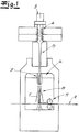
- the Fig. 1 shows an apparatus for producing nonwoven fabric layers (1, 2) in the form of spunbonded webs for the laminate according to the invention.
- continuous filaments are produced by the spunbond process and deposited to spunbonded.
- filaments 1 'or endless filaments are spun and then preferably guided and, in the exemplary embodiment, for cooling by a cooling device 4.
- the cooling device 4 is followed by a drawing device 6 with a drawing shaft 7.
- To the cooling device 4 includes preferably and in the embodiment, an intermediate channel 5, which the cooling device 4 with the stretching device 6 connects. Empfohlene866 and in the embodiment of the drawing device 6 downstream of a diffuser 8 in the flow direction of the filaments 1 '.
- the unit of the cooling device 4 and the drafting device 6 and the unit of the cooling device 4, the intermediate channel 5 and the drawing device 6 is formed as a closed system.
- this closed unit except the supply of cooling air in the cooling device 4 no further air supply from the outside.
- both nonwoven fabric layers 1, 2 of the laminate 10 according to the invention as a spunbonded nonwoven with a in Fig.1 produced device generated.
- a nonwoven fabric layer 1, 2 or both nonwoven fabric layers 1, 2 can also be produced as meltblown nonwovens by a meltblown process.
- the on the in Fig. 1 Filing screen belt 9 deposited nonwoven fabric layer 1, 2 is then fed to further processing.
- the (single) nonwoven fabric layer 1,2 is preconsolidated after being deposited, and indeed in the exemplary embodiment Fig. 1 by means of a calender 11.
- a (single) nonwoven layer 1, 2 is calendered using an open calendering structure.
- the nonwoven fabric layer 1, 2 expediently becomes combined with another nonwoven fabric layer 1,2 to form an aggregate or laminate according to the invention.
- This further nonwoven fabric layer 1,2 can also according to a preferred embodiment with a device of in Fig.
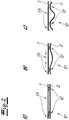
- the Fig. 2 shows an aggregate of a first nonwoven fabric layer 1 and a second nonwoven fabric layer 2.
- the first nonwoven fabric layer 1 has a higher shrinkability or a higher shrinkage potential than the second nonwoven fabric layer 2.
- the aggregate is shown before shrinkage activation.
- the aggregate of the two nonwoven fabric layers 1, 2 has already been solidified so that solidification regions 12 or solidification points and solidification-free regions 13 are present.
- the solidification was carried out as a thermal consolidation and in the solidification regions 12 and in the solidification points are endless filaments of the two nonwoven fabric layers 1,2 fused together.
- the unit of the two nonwoven fabric layers 1,2 is then thermally activated or heated to an activation temperature.
- the first nonwoven fabric layer 1 shrinks with the higher shrinkage potential. This is through the arrows in the Fig. 2 b) been hinted at. Because of this shrinkage or due to this contraction of the solidification regions 12, solidification-free regions of the second nonwoven fabric layer 2 are displaced or raised transversely, in particular perpendicular to the surface extension of the aggregate.
- the figure c) shows the final state of the unit after the thermal shrinkage. It is recognizable that due to the shrinkage activation or due to the shrinkage, a pronounced 3D structure of the aggregate or laminate 10 with a clear z-component transversely, in particular perpendicular to the surface of the laminate 10 is present.
- FIG. 3 a shows a perspective view of an aggregate of two nonwoven fabric layers 1,2 in the already solidified state with solidification areas 12 and solidification-free areas 13. Die FIG. 3 b) shows this unit after the shrinkage activation with the upwardly shifted solidification-free regions 13 of the second nonwoven fabric layer second
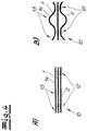
- Fig. 4 is a section through an aggregate of three nonwoven fabric layers 1, 2, 14 shown.
- the middle nonwoven fabric layer 1 in this case has a higher shrinkability or a higher shrinkage potential than the two outer nonwoven fabric layers 2 and 14.
- These two non-shrinking or less shrinking outer nonwoven fabric layers 2, 14 may be identical in the embodiment. In principle, however, it is also possible to use different nonwoven fabric layers 2, 14 as outer nonwoven fabric layers.
- the aggregate is shown before shrinkage activation.
- the aggregate of the three nonwoven fabric layers 1, 2, 14 has already been solidified, so that solidification regions 12 or solidification points and solidification-free regions 13 are present. This three-layer aggregate is then thermally activated or heated to an activation temperature.
- the average nonwoven fabric layer 1 shrinks with the higher shrinkage potential. That's like in the Fig. 2 indicated by arrows. Due to the shrinkage or due to the contraction of the solidification regions 12, solidification-free regions of the two outer nonwoven fabric layers 2, 14 are moved transversely, in particular perpendicularly to the surface extension of the aggregate or raised. In Fig. 4b ) already shows the final state of the unit after the thermal shrinkage.
Landscapes
- Engineering & Computer Science (AREA)
- Textile Engineering (AREA)
- Physics & Mathematics (AREA)
- Thermal Sciences (AREA)
- Mechanical Engineering (AREA)
- Nonwoven Fabrics (AREA)
- Laminated Bodies (AREA)
Description
Die Erfindung betrifft ein Verfahren zur Herstellung eines Laminates mit zumindest zwei übereinander angeordneten Vliesstoff-Lagen aus Endlosfilamenten, insbesondere aus Endlosfilamenten aus thermoplastischem Kunststoff, wobei das Aggregat der zumindest zwei aufeinander angeordneten Vliesstoff-Lagen mit der Maßgabe verfestigt wird, dass über die Fläche des Aggregates Verfestigungsbereiche und verfestigungsfreie Bereiche verteilt angeordnet sind. Die Erfindung betrifft fernerhin ein Laminat mit zumindest zwei übereinander angeordneten Vliesstoff-Lagen aus Endlosfilamenten. - Im Rahmen der Erfindung werden Vliesstoff-Lagen aus Endlosfilamenten eingesetzt. Bekanntlich unterscheiden sich Endlosfilamente aufgrund ihrer quasi endlosen Länge von Stapelfasern, die viel geringere Längen von beispielsweise 10 mm bis 60 mm aufweisen.The invention relates to a method for producing a laminate with at least two superimposed nonwoven fabric layers of continuous filaments, in particular of continuous filaments of thermoplastic material, wherein the aggregate of at least two nonwoven fabric layers arranged on each other is solidified with the proviso that over the surface of the unit Solidification areas and solidification free areas are distributed. The invention further relates to a laminate having at least two superimposed nonwoven fabric layers of continuous filaments. In the context of the invention, nonwoven fabric layers of continuous filaments are used. As is known, continuous filaments differ because of their quasi-endless length of staple fibers, which have much smaller lengths of, for example, 10 mm to 60 mm.
In der Praxis ist es häufig wünschenswert Vliesprodukte bzw. Vliesstoff-Lagen mit voluminöser Charakteristik zu erzeugen. Diese Vliesprodukte sollen eine relativ große Dicke bzw. ein verhältnismäßig hohes Volumen aufweisen. Eine Möglichkeit hierzu besteht darin, den Vliesstoffen bzw. Vliesstoff-Lagen eine "3D-Struktur" mit ausgeprägter Strukturausrichtung quer bzw. senkrecht zur Fläche des Vliesstoffes (in z-Richtung) aufzuerlegen.In practice, it is often desirable to produce nonwoven webs or webs having bulky characteristics. These nonwoven products should have a relatively large thickness or a relatively high volume. One possibility for this is to impose on the nonwoven fabrics or nonwoven fabric layers a "3D structure" with a pronounced structural orientation transversely or perpendicular to the surface of the nonwoven fabric (in the z direction).
Eine solche "3D-Struktur" wird bei den aus dem Stand der Technik bekannten Maßnahmen insbesondere durch Prägen eines Vliesstoffes bzw. eines Vliesstoff-Aggregates erreicht. Dazu kann beispielsweise ein gekräuselte Fasern aufweisender Vliesstoff eingesetzt werden. Das Prägen des Vliesstoffes führt zum einen zur Realisierung der 3D-Struktur. Zum anderen wird in den Prägebereichen die Dicke des Vliesstoffes aber auch reduziert und im Übrigen sind dem Prägeverfahren in Bezug auf Geschwindigkeit und erzielbare Produktbreite Grenzen gesetzt. Vor allem bei geringeren Flächengewichten ist die erreichbare Dicke normalerweise nicht zufriedenstellend. Die auf die vorstehend beschriebene Weise behandelten Vliesstoffe sind in der Regel nicht ausreichend druckstabil bzw. zeigen nach einer Druckbelastung ein unzureichendes Wiederaufstellvermögen in den belasteten Bereichen.Such a "3D structure" is achieved in the measures known from the prior art, in particular by embossing a nonwoven fabric or a nonwoven aggregate. For this purpose, for example, a crimped fibers having nonwoven fabric can be used. The embossing of the nonwoven fabric leads on the one hand to the realization of the 3D structure. On the other hand, in the embossing areas, the thickness of the nonwoven fabric is also reduced and, moreover, are the embossing process in terms of speed and achievable product width Set limits. Especially at lower basis weights, the achievable thickness is usually not satisfactory. The nonwoven fabrics treated in the manner described above are generally not sufficiently pressure-stable or, after pressure loading, show insufficient recovery in the loaded areas.
Aus
Weiterhin ist aus
Der Erfindung liegt das technische Problem zugrunde, ein Verfahren der eingangs genannten Art anzugeben, bei dem die vorstehend geschilderten Nachteile vermieden werden können und mit dem auf einfache und wenig aufwendige Weise ein Laminat erzeugt werden kann, das ein hohes Volumen bzw. eine große Dicke und zugleich eine hohe Druckstabilität sowie ein gutes Wiederaufstellvermögen aufweist. Der Erfindung liegt fernerhin das technische Problem zugrunde, ein entsprechendes Laminat anzugeben.The invention is based on the technical problem to provide a method of the type mentioned, in which the above-described disadvantages can be avoided and with the simple and inexpensive manner a laminate can be produced, which has a high volume or a large thickness and at the same time a high pressure stability and a good Wiederaufstellvermögen has. The invention is further based on the technical problem of specifying a corresponding laminate.
Zur Lösung des technischen Problems lehrt die Erfindung ein Verfahren zur Herstellung eines Laminates mit zumindest zwei übereinander angeordneten Vliesstoff-Lagen aus Endlosfilamenten, insbesondere aus Endlosfilamenten aus thermoplastischem Kunststoff,
wobei eine erste Vliesstoff-Lage erzeugt wird, die eine höhere Schrumpffähigkeit bzw. ein höheres Schrumpfpotential in Richtung ihrer Flächenausdehnung aufweist als eine zweite Vliesstoff-Lage, wobei die erste Vliesstoff-Lage mittels eines Spunbond-Verfahrens und/oder mittels eines Meltblown-Verfahrens aus Mehrkomponentenfilamenten, insbesondere aus Bikomponentenfilamenten erzeugt wird,
wobei die zweite Vliesstoff-Lage mittels eines Spunbond-Verfahrens oder mittels eines Meltblown-Verfahrens aus Mehrkomponentenfilamenten - insbesondere aus Bikomponentenfilamenten - und/oder aus Monokomponentenfilamenten erzeugt wird und mit der ersten Vliesstoff-Lage bevorzugt unmittelbar flächig kombiniert bzw. zusammengeführt wird, insbesondere bevorzugt unmittelbar auf der ersten Vliesstoff-Lage abgelegt wird,
wobei das Aggregat der zumindest zwei bzw. der beiden unmittelbar aufeinander angeordneten Vliesstoff-Lagen mit der Maßgabe verfestigt wird, dass über die Fläche des Aggregates Verfestigungsbereiche und verfestigungsfreie Bereiche verteilt angeordnet sind, wobei im Anschluss an die Verfestigung das Schrumpfen der ersten Vliesstoff-Lage aktiviert wird, so dass als Folge der Schrumpfung der ersten Vliesstoff-Lage verfestigungsfreie Bereiche der zweiten Vliesstoff-Lage quer, insbesondere senkrecht zur Flächenausdehnung des Aggregates verschoben bzw. angehoben werden und wobei ein Laminat mit einer Dicke D unter 2 mm erzeugt wird.To solve the technical problem, the invention teaches a method for producing a laminate with at least two superimposed nonwoven fabric layers of continuous filaments, in particular of continuous filaments of thermoplastic material,
wherein a first nonwoven fabric layer is produced, which has a higher shrinkage potential or a higher shrinkage potential in the direction of their surface area than a second nonwoven fabric layer, wherein the first nonwoven fabric layer by means of a spunbond process and / or by means of a meltblown process Multi-component filaments, in particular of bicomponent filaments is produced,
wherein the second nonwoven fabric layer is produced by means of a spunbond process or by means of a meltblown process of multicomponent filaments - in particular of bicomponent filaments - and / or monocomponent filaments and preferably combined or combined with the first nonwoven fabric layer directly on the surface, particularly preferably directly is deposited on the first nonwoven layer,
wherein the aggregate of the at least two or the two directly non-woven fabric layers is solidified with the proviso, that solidification regions and solidification-free regions are distributed over the surface of the aggregate, after which the shrinkage of the first nonwoven fabric layer is activated following the solidification, so that as a result of the shrinkage of the first nonwoven fabric layer, solidification-free regions of the second nonwoven fabric layer transversely, be moved or raised in particular perpendicular to the surface area of the unit and wherein a laminate is produced with a thickness D less than 2 mm.
Eine sehr empfohlene Ausführungsform der Erfindung ist dadurch gekennzeichnet, dass die erste Vliesstoff-Lage als Spinnvlies mittels eines Spunbond-Verfahrens erzeugt wird. Diese Ausführungsform der Erfindung hat sich ganz besonders bewährt. Die Mehrkomponentenfilamente bzw. Bikomponentenfilamente für die erste Vliesstoff-Lage werden mittels einer Spinneinrichtung bzw. Spinnerette ersponnen und anschließend bevorzugt zur Kühlung durch eine Kühlvorrichtung geführt. In der Kühlvorrichtung werden die Filamente zweckmäßigerweise mit einem fluiden Medium, insbesondere mit Kühlluft gekühlt. Es liegt im Rahmen der Erfindung, dass die aus der Kühlvorrichtung austretenden Filamente anschließend durch eine Verstreckeinrichtung geführt werden, mit deren Hilfe die Filamente verstreckt werden. Insbesondere durch Einstellung der Verstreckparameter kann erreicht werden, dass die aus den Filamenten gebildete erste Vliesstoff-Lage ein höheres Schrumpfpotential aufweist als die zweite Vliesstoff-Lage. Die verstreckten Filamente werden im Anschluss daran auf einer Ablage - vorzugsweise auf einem Ablagesiebband - zur ersten Vliesstoff-Lage abgelegt. Gemäß einer bevorzugten Ausführungsform ist zwischen der Verstreckeinrichtung und der Ablage zumindest ein Diffusor als Ablageeinrichtung zwischengeschaltet, durch den die Filamente geführt werden. Es liegt im Rahmen der Erfindung, dass der zumindest eine Diffusor gegenüberliegende, in Bezug auf die Strömungsrichtung der Filamente divergierende Seitenwände aufweist. Eine besonders empfohlene Ausführungsform der Erfindung ist dadurch gekennzeichnet, dass das Aggregat aus der Kühlvorrichtung und der Verstreckeinrichtung als geschlossenes System ausgebildet ist. Bei diesem geschlossenen Aggregat erfolgt außer der Zufuhr von Kühlmedium bzw. Kühlluft in der Kühlvorrichtung keine weitere Luftzufuhr von außen. Ein solches geschlossenes System hat sich für die Erzeugung der ersten Vliesstoff-Lage im Rahmen der Erfindung ganz besonders bewährt. - Grundsätzlich kann die erste Vliesstoff-Lage auch mittels eines Meltblown-Verfahrens hergestellt werden.A highly recommended embodiment of the invention is characterized in that the first nonwoven fabric layer is produced as a spunbonded fabric by means of a spunbond process. This embodiment of the invention has proven particularly useful. The multicomponent filaments or bicomponent filaments for the first nonwoven fabric layer are spun by means of a spinnerette and then preferably passed through a cooling device for cooling. In the cooling device, the filaments are expediently cooled with a fluid medium, in particular with cooling air. It is within the scope of the invention that the emerging from the cooling device filaments are then passed through a drawing device, by means of which the filaments are stretched. In particular, by adjusting the stretching parameters, it can be achieved that the first nonwoven fabric layer formed from the filaments has a higher shrinkage potential than the second nonwoven fabric layer. The stretched filaments are then deposited on a tray - preferably on a Ablagesiebband - to the first nonwoven fabric layer. According to a preferred embodiment, at least one diffuser is interposed between the stretching device and the tray as a depositing device, through which the filaments are guided. It is within the scope of the invention that the at least one diffuser has opposite, with respect to the flow direction of the filaments diverging side walls. A particularly recommended embodiment the invention is characterized in that the unit of the cooling device and the drawing device is designed as a closed system. In this closed aggregate except the supply of cooling medium or cooling air in the cooling device no further air supply from the outside. Such a closed system has proven particularly useful for the production of the first nonwoven layer in the context of the invention. In principle, the first nonwoven fabric layer can also be produced by means of a meltblown process.
Eine weitere sehr empfohlene Ausführungsform des erfindungsgemäßen Verfahrens zeichnet sich dadurch aus, dass die zweite Vliesstoff-Lage als Spinnvlies mittels eines Spunbond-Verfahrens erzeugt wird. Für dieses Spunbond-Verfahren bzw. die zugehörige Spunbond-Vorrichtung gilt auch die vorstehend für die erste Vliesstoff-Lage angegebene Beschreibung bzw. deren Merkmale. - Gemäß einer anderen Ausführungsvariante wird die zweite Vliesstoff-Lage mittels eines Meltblown-Verfahrens erzeugt.Another highly recommended embodiment of the method according to the invention is characterized in that the second nonwoven fabric layer is produced as a spunbonded fabric by means of a spunbond process. For this spunbond method or the associated spunbond apparatus, the description or characteristics given above for the first nonwoven fabric layer also applies. - According to another embodiment variant, the second nonwoven fabric layer is produced by means of a meltblown process.
Wie oben bereits dargelegt hat sich vor allem zur Herstellung der ersten Vliesstoff-Lage ein Spunbond-Verfahren besonders bewährt. Es hat sich gezeigt, dass das erfindungsgemäße technische Problem mit der erfindungsgemäßen Schrumpfung besonders funktionssicher und effektiv gelöst wird, wenn das beschriebene geschlossene Aggregat eingesetzt wird und wenn zusätzlich nach besonders bevorzugter Ausführungsvariante zumindest ein Diffusor zwischen Verstreckeinrichtung und Ablage verwendet wird. Es wurde bereits angedeutet, dass über die Verstreckparameter des Spunbond-Verfahrens das Schrumpfpotential für die erste Vliesstoff-Lage sehr gezielt eingestellt bzw. gesteuert werden kann.As already explained above, a spunbond process has proven particularly useful, especially for the production of the first nonwoven layer. It has been found that the inventive technical problem with the shrinkage according to the invention is particularly reliable and effectively solved when the described closed unit is used and if in addition to a particularly preferred embodiment, at least one diffuser between drawing device and storage is used. It has already been indicated that the shrinkage potential for the first nonwoven fabric layer can be set or controlled in a very targeted manner via the stretching parameters of the spunbond process.
Es empfiehlt sich, dass das Verhältnis der Flächengewichte der ersten (stärker schrumpfenden) Vliesstoff-Lage zur zweiten (weniger schrumpfenden) Vliesstoff-Lage 25:75 bis 75:25 beträgt. Das gilt bevorzugt auch für das Verhältnis zweier entsprechender Vliesstoff-Lagen in einem 3-lagigen oder mehrlagigen Laminat. - Zweckmäßigerweise beträgt die Masse der ersten Vliesstoff-Lage in dem Aggregat aus den beiden Vliesstoff-Lagen bis zu 70 % der Gesamtmasse des Aggregates. - Eine empfohlene Ausführungsform der Erfindung ist dadurch gekennzeichnet, dass die erste Vliesstoff-Lage als vorverfestigte bzw. verfestigte Vliesstoff-Lage eingesetzt wird. Dabei wird die erste Vliesstoff-Lage bevorzugt thermisch vorverfestigt bzw. verfestigt, beispielsweise mit einem Kalander thermisch vorverfestigt bzw. verfestigt. Die Vorverfestigung bzw. Verfestigung erfolgt dabei zweckmäßigerweise mit einer offenen Kalanderstruktur.It is recommended that the ratio of the basis weights of the first (more shrinking) nonwoven layer to the second (less shrinking) nonwoven layer is 25:75 to 75:25. This preferably also applies to the ratio of two corresponding nonwoven fabric layers in a 3-layer or multilayer laminate. - Expediently, the mass of the first nonwoven fabric layer in the aggregate of the two nonwoven fabric layers is up to 70% of the total mass of the aggregate. A recommended embodiment of the invention is characterized in that the first nonwoven fabric layer is used as a pre-consolidated or consolidated nonwoven fabric layer. In this case, the first nonwoven fabric layer is preferably thermally pre-consolidated or solidified, for example thermally preconsolidated or solidified with a calender. The preconsolidation or solidification is expediently carried out with an open calender structure.
Es liegt im Rahmen der Erfindung, dass die unterschiedlichen Schrumpffähigkeiten bzw. die unterschiedlichen Schrumpfpotentiale der beiden Vliesstoff-Lagen durch unterschiedliche Rohstoffe für die Endlosfilamente der beiden Vliesstoff-Lagen und/oder durch unterschiedliche Prozessbedingungen bei der Erzeugung bzw. beim Spinnen der Endlosfilamente für die beiden Vliesstoff-Lagen und/oder durch unterschiedliche Filamentquerschnitte der Endlosfilamente der beiden Vliesstoff-Lagen und/oder durch unterschiedliche Orientierungen der Endlosfilamente in den beiden Vliesstoff-Lagen eingestellt werden.It is within the scope of the invention that the different shrinkage capabilities or the different shrinkage potentials of the two nonwoven fabric layers by different raw materials for the continuous filaments of the two nonwoven fabric layers and / or by different process conditions in the production or spinning of the continuous filaments for the two Nonwoven layers and / or be set by different filament cross sections of the continuous filaments of the two nonwoven fabric layers and / or by different orientations of the continuous filaments in the two nonwoven fabric layers.
Eine besonders empfohlene Ausführungsform des erfindungsgemäßen Verfahrens ist dadurch gekennzeichnet, dass die Schrumpffähigkeit bzw. das Schrumpfpotential der ersten Vliesstoff-Lage in Maschinenrichtung (MD) größer ist als die Schrumpffähigkeit bzw. das Schrumpfpotential dieser ersten Vliesstoff-Lage quer zur Maschinenrichtung (CD). Maschinenrichtung meint dabei insbesondere die Produktionsrichtung bzw. die Förderrichtung der ersten Vliesstoff-Lage bei der Erzeugung bzw. beim Erspinnen der ersten Vliesstoff-Lage. Bei der Herstellung der ersten Vliesstoff-Lage werden die Filamente für diese Vliesstoff-Lage zweckmäßigerweise auf einer bewegten Ablage und bevorzugt auf einem bewegten Ablageband bzw. Ablagesiebband abgelegt. Maschinenrichtung meint dann insbesondere die Förderrichtung dieser Ablage bzw. dieses Ablagesiebbandes. Quer zur Maschinenrichtung (CD) meint insbesondere die Richtung quer zu dieser Förderrichtung.A particularly recommended embodiment of the method according to the invention is characterized in that the shrinkability or the shrinkage potential of the first nonwoven fabric layer in the machine direction (MD) is greater than the shrinkability or the shrinkage potential of this first nonwoven fabric layer transversely to the machine direction (CD). Machine direction means in particular the production direction or the conveying direction of the first Nonwoven fabric layer during production or during spinning of the first nonwoven fabric layer. In the production of the first nonwoven fabric layer, the filaments for this nonwoven fabric layer are expediently deposited on a moving support and preferably on a moving deposition belt or filing belt. Machine direction then means in particular the conveying direction of this tray or this Ablagesiebbandes. Transverse to the machine direction (CD) means in particular the direction transverse to this conveying direction.
Besonders bevorzugt ist eine Ausführungsform des erfindungsgemäßen Verfahrens, bei der eine erste Vliesstoff-Lage eingesetzt wird, bei der das Verhältnis der Schrumpffähigkeit (Schrumpfpotential) in Maschinenrichtung (MD) zur Schrumpffähigkeit (Schrumpfpotential) quer zur Maschinenrichtung (CD) 1:1 bis 3:1, vorzugsweise 1,1:1 bis 1,6:1 und besonders bevorzugt 1,1:1 bis 1,5:1 beträgt. Wenn hier und nachfolgend von Schrumpffähigkeit bzw. Schrumpfpotential die Rede ist, meint dies insbesondere die Schrumpffähigkeit bzw. das Schrumpfpotential bei der Aktivierungstemperatur, auf die bei der thermischen Aktivierung erhitzt bzw. erwärmt wird. Schrumpffähigkeit bzw. Schrumpfpotential meint fernerhin den freien Schrumpf bzw. den freien Schrumpf der ersten Vliesstoff-Lage ohne irgendwelche Behinderungen / mechanischen Behinderungen der Schrumpfung. Gemäß besonders empfohlener Ausführungsform der Erfindung ist das Schrumpfpotential in MD-Richtung der ersten Vliesstoff-Lage 10 bis 60%, bevorzugt 15 bis 50% größer als das Schrumpfpotential in CD-Richtung.Particularly preferred is an embodiment of the method according to the invention, in which a first nonwoven fabric layer is used, in which the ratio of the shrinkage (shrinkage potential) in the machine direction (MD) to the shrinkability (shrinkage potential) transverse to the machine direction (CD) 1: 1 to 3: 1, preferably 1.1: 1 to 1.6: 1 and more preferably 1.1: 1 to 1.5: 1. If, here and below, the term shrinkability or shrinkage potential is mentioned, this means in particular the shrinkability or the shrinkage potential at the activation temperature to which heating or heating is effected during the thermal activation. Shrinkability also means the free shrinkage or free shrinkage of the first nonwoven layer without any obstruction / mechanical impediments to shrinkage. According to a particularly recommended embodiment of the invention, the shrinkage potential in the MD direction of the first nonwoven fabric layer is 10 to 60%, preferably 15 to 50%, greater than the shrinkage potential in the CD direction.
Das Schrumpfpotential wird empfohlenermaßen nach der folgenden Messmethode gemessen: Eine quadratische Vliesprobe mit 100 mm Kantenlänge (Quadrat: 100 mm x 100 mm) wird in einem heißen Fluid 1 Minute lang bei der Aktivierungstemperatur erhitzt. Als Fluid sind beispielsweise Luft, Wasser, Silikonöl oder dergleichen fluides Medium geeignet. Nach Entnahme und Abkühlung der Vliesprobe werden die geschrumpften Längen gemessen und zwar in Maschinenrichtung (MD) und quer zur Maschinenrichtung (CD). Die Schrumpfung wird in % gegen die 100 mm angegeben. Wenn also eine Vliesprobe nach der Schrumpfung in einer gemessenen Richtung 60 mm lang ist, so weist die Vliesprobe in dieser Richtung eine Schrumpfung von 40 % auf. Auf diese Weise kann das Verhältnis der Schrumpfpotentiale MD / CD in den beiden Richtungen ermittelt und angegeben werden.The shrinkage potential is recommended to be measured according to the following measurement method: A square non-woven sample of 100 mm edge length (square: 100 mm x 100 mm) is heated in a hot fluid for 1 minute at the activation temperature. As the fluid, for example, air, water, silicone oil or the like fluid medium are suitable. After removal and cooling In the nonwoven sample, the shrunken lengths are measured in the machine direction (MD) and cross machine direction (CD). The shrinkage is given in% against the 100 mm. Thus, if a nonwoven sample after shrinkage in a measured direction is 60 mm long, the nonwoven sample will have a shrinkage of 40% in that direction. In this way, the ratio of the shrinkage potentials MD / CD in the two directions can be determined and specified.
Empfohlenermaßen weist die erste Vliesstoff-Lage bei der Aktivierungstemperatur in Maschinenrichtung (MD) ein Schrumpfpotential von 20 bis 80 % auf. Gemäß einer Ausführungsform der Erfindung wird das Schrumpfpotential in Maschinenrichtung (MD) und/oder quer - insbesondere senkrecht - zur Maschinenrichtung (CD) lediglich im Bereich von 10 bis 80 %, bevorzugt im Bereich von 10 bis 50 % des jeweiligen gesamten Schrumpfpotentials ausgenutzt. Wenn somit beispielsweise die erste Vliesstoff-Lage in Maschinenrichtung ein Schrumpfpotential von 50 % aufweist und 50 % dieses Schrumpfpotentials ausgenutzt werden, so hat diese Vliesstoff-Lage in Maschinenrichtung eine Endlänge von 75 % der ursprünglichen Länge, also eine um 25 % geringere Länge. - Die Verschiebung bzw. Anhebung der verfestigungsfreien Bereiche der zweiten Vliesstoff-Lage quer, insbesondere senkrecht zur Flächenausdehnung des Aggregates (in z-Richtung) wird zufriedenstellend nur bei ausreichendem Schrumpfpotentialunterschied zwischen der ersten (stärker schrumpfenden) Vliesstoff-Lage und der zweiten (weniger schrumpfenden) Vliesstoff-Lage erreicht. In diesem Zusammenhang hat sich bewährt, dass die zweite Vliesstoff-Lage bei der Aktivierungstemperatur ein Schrumpfpotential von maximal 50 %, vorzugsweise maximal 30 % und bevorzugt maximal 20 % des Schrumpfpotentials der ersten Vliesstoff-Lage besitzt. Wenn also die erste Vliesstoff-Lage ein Schrumpfpotential von beispielsweise 50 % aufweist, so besitzt die zweiteIt is recommended that the first nonwoven fabric layer has a shrinkage potential of 20 to 80% at the machine direction (MD) activation temperature. According to one embodiment of the invention, the shrinkage potential in the machine direction (MD) and / or transversely - in particular perpendicular - to the machine direction (CD) is utilized only in the range of 10 to 80%, preferably in the range of 10 to 50% of the respective total shrinkage potential. Thus, if, for example, the first nonwoven fabric layer has a shrinkage potential of 50% in the machine direction and 50% of this shrinkage potential is utilized, this nonwoven fabric layer has a final length of 75% of the original length in the machine direction, ie a length 25% shorter. The displacement or elevation of the solidification-free regions of the second nonwoven layer transversely, in particular perpendicular to the surface extension of the aggregate (in the z direction) is satisfactorily only with sufficient shrink potential difference between the first (more shrinking) nonwoven layer and the second (less shrinking ) Nonwoven fabric layer reached. In this context, it has been proven that the second nonwoven fabric layer at the activation temperature has a shrinkage potential of not more than 50%, preferably not more than 30% and preferably not more than 20% of the shrinkage potential of the first nonwoven fabric layer. Thus, if the first nonwoven fabric layer has a shrinkage potential of, for example, 50%, the second one has
(weniger schrumpfende) Vliesstoff-Lage vorzugsweise ein Schrumpfpotential von unter 10 %. Es empfiehlt sich, dass die zweite (weniger schrumpfende) Vliesstoff-Lage bei der Aktivierungstemperatur ein Schrumpfpotential von 0 bis 50 %, vorzugsweise von 0 bis 20 % und sehr bevorzugt von 0 bis 10 % aufweist.(less shrinking) nonwoven layer preferably has a shrinkage potential of less than 10%. It is recommended that the second (less shrinking) nonwoven fabric layer at the activation temperature has a shrinkage potential of 0 to 50%, preferably from 0 to 20% and very preferably from 0 to 10%.
Eine besonders empfohlene Ausführungsform des erfindungsgemäßen Verfahrens zeichnet sich dadurch aus, dass die erste Vliesstoff-Lage aus Mehrkomponentenfilamenten, insbesondere aus Bikomponentenfilamenten, mit Kern-Mantel-Konfiguration erzeugt wird. Zweckmäßigerweise ist die Differenz zwischen der Schmelztemperatur der Kernkomponente und der Schmelztemperatur der Mantelkomponente größer als 5°C, nach einer bevorzugten Ausführungsform größer als 10°C. Es liegt im Rahmen der Erfindung, dass die Kernkomponente aus einem Kunststoff aus der Gruppe "Polyester, Polyolefin, Polylactid" besteht bzw. im Wesentlichen besteht. Als Polyester wird dabei vorzugsweise Polyethylenterephthalat (PET) eingesetzt und als Polyolefin wird empfohlenermaßen Polypropylen (PP) verwendet. Weiterhin liegt es im Rahmen der Erfindung, dass die Mantelkomponente der Mehrkomponentenfilamente bzw. Bikomponentenfilamente der ersten Vliesstoff-Lage aus einem Kunststoff aus der Gruppe "Polyolefin, Polyester-Copolymer, Polylactid-Copolymer (CoPLA)" besteht bzw. im Wesentlichen besteht. Als Polyolefin wird dabei zweckmäßigerweise Polyethylen (PE) eingesetzt und als Polyester-Copolymer wird vorzugsweise Polyethylenterephthalat-Copolymer (CoPET) verwendet. Bevorzugte Kern-Mantel-Kombinationen für die Mehrkomponentenfilamente bzw. Bikomponentenfilamente der ersten Vliesstoff-Lage sind PET/PE, PET/PP, PET/CoPET, PLA/CoPLA und PLA/PP. - Das Massenverhältnis der Kernkomponente zur Mantelkomponente beträgt nach einer Ausführungsform 50:50 bis 90:10. Es liegt im Rahmen des erfindungsgemäßen Verfahrens, dass diese Massenverhältnisse der Kern-Mantel-Konfiguration während der Produktion ohne Stillstand der Maschine frei variiert werden können.A particularly recommended embodiment of the method according to the invention is characterized in that the first nonwoven fabric layer is produced from multi-component filaments, in particular from bicomponent filaments, with a core-sheath configuration. Conveniently, the difference between the melting temperature of the core component and the melting temperature of the shell component is greater than 5 ° C, according to a preferred embodiment, greater than 10 ° C. It is within the scope of the invention that the core component consists of a plastic from the group "polyester, polyolefin, polylactide" or consists essentially. Polyethylene terephthalate (PET) is preferably used as the polyester, and polypropylene (PP) is recommended as the polyolefin. Furthermore, it is within the scope of the invention for the sheath component of the multi-component filaments or bicomponent filaments of the first nonwoven fabric layer to consist essentially of a plastic from the group "polyolefin, polyester copolymer, polylactide copolymer (CoPLA)". Polyethylene (PE) is expediently used as the polyolefin, and polyethylene terephthalate copolymer (CoPET) is preferably used as the polyester copolymer. Preferred core / sheath combinations for the multicomponent filaments or bicomponent filaments of the first nonwoven layer are PET / PE, PET / PP, PET / CoPET, PLA / CoPLA and PLA / PP. The mass ratio of the core component to the sheath component is 50:50 to 90:10 in one embodiment. It is within the scope of the process according to the invention that these mass ratios of the core-shell configuration can be freely varied during production without stopping the machine.
Es liegt im Rahmen der Erfindung, dass die zweite Vliesstoff-Lage aus Mehrkomponentenfilamenten, insbesondere aus Bikomponentenfilamenten, mit Kern-Mantel-Konfiguration und/oder mit Seite-Seite-Konfiguration erzeugt wird. Wenn die Mehrkomponentenfilamente bzw. Bikomponentenfilamente der zweiten Vliesstoff-Lage nach besonders bevorzugter Ausführungsform eine Kern-Mantel-Konfiguration aufweisen, besteht der Kern empfohlenermaßen aus einem Kunststoff aus der Gruppe "Polyester, Polylactid (PLA), Polyolefin". Als Polyester wird dabei bevorzugt Polyethylenterephthalat (PET) eingesetzt. Als Polyolefin für die Kernkomponente empfiehlt sich insbesondere Polypropylen (PP). Als Mantelkomponente für die Mehrkomponentenfilamente bzw. Bikomponentenfilamente der zweiten Vliesstoff-Lage wird vorzugsweise ein Kunststoff aus der Gruppe "Polyester-Copolymer, Polylactid-Copolymer (CoPLA), Polyolefin" verwendet. Als Polyolefin empfiehlt sich dabei insbesondere Polyethylen. Als Polyester-Copolymer wird zweckmäßigerweise Polyethylenterephthalat-Copolymer (CoPET) eingesetzt. Wenn für die zweite Vliesstoff-Lage Bikomponentenfilamente mit Kern-Mantel-Konfiguration verwendet werden, bestehen nach einer Ausführungsform sowohl die Kernkomponente als auch die Mantelkomponente aus einem Polyolefin, insbesondere aus Polypropylen und/oder Polyethylen. Die Kernkomponente wird bevorzugt von einem Polypropylen gebildet und die Mantelkomponente zweckmäßigerweise entweder von Polyethylen oder von einem Polypropylen, das unterschiedlich zu dem Polypropylen der Kernkomponente ist. - Die für die zweite Vliesstoff-Lage verwendeten Mehrkomponentenfilamente bzw. Bikomponentenfilamente können gemäß einer Ausführungsform auch eine Seite-Seite-Konfiguration aufweisen. Bei dieser Ausführungsform bestehen bewährtermaßen beide Seitenkomponenten aus einem Polyolefin, insbesondere aus Polypropylen und/oder Polyethylen. Grundsätzlich können für die Filamente der zweiten Vliesstoff-Lage auch Monokomponentenfilamente eingesetzt werden. Diese Monokomponentenfilamente bestehen dann empfohlenermaßen aus einem Polyolefin, vorzugsweise aus Polyethylen oder Polypropylen.It is within the scope of the invention that the second nonwoven layer is produced from multi-component filaments, in particular from bicomponent filaments, with a core-sheath configuration and / or with side-side configuration. If the multi-component filaments or bicomponent filaments of the second nonwoven fabric layer according to a particularly preferred embodiment have a core-sheath configuration, the core is recommended to be made of a plastic from the group "polyester, polylactide (PLA), polyolefin". The polyester used is preferably polyethylene terephthalate (PET). Polypropylene (PP) is especially recommended as the polyolefin for the core component. As a shell component for the multi-component filaments or bicomponent filaments of the second nonwoven fabric layer, a plastic from the group "polyester copolymer, polylactide copolymer (CoPLA), polyolefin" is preferably used. In particular, polyethylene is recommended as the polyolefin. As the polyester copolymer, polyethylene terephthalate copolymer (CoPET) is suitably used. When bicomponent bicomponent filaments are used for the second nonwoven layer, according to one embodiment, both the core component and the sheath component are made of a polyolefin, in particular of polypropylene and / or polyethylene. The core component is preferably formed from a polypropylene and the sheath component suitably formed either from polyethylene or from a polypropylene which is different from the polypropylene of the core component. The multi-component filaments or bicomponent filaments used for the second nonwoven fabric layer may also have a side-side configuration according to one embodiment. In this embodiment, both side components are proven to consist of a polyolefin, in particular of polypropylene and / or Polyethylene. In principle, monocomponent filaments can also be used for the filaments of the second nonwoven fabric layer. These monocomponent filaments are then recommended to be made of a polyolefin, preferably polyethylene or polypropylene.
Nachfolgend werden drei ganz besonders bevorzugte Ausführungsformen für Bikomponentenfilamente der ersten Vliesstoff-Lage und der zweiten Vliesstoff-Lage angegeben:
Bei diesen Ausführungsformen entsprechen die Materialkombinationen der Bikomponentenfilamente der stärker schrumpfenden ersten Vliesstoff-Lage den Materialkombinationen der zweiten weniger schrumpfenden Vliesstoff-Lage. Die höhere Schrumpffähigkeit der ersten Vliesstoff-Lage wird dabei vorzugsweise durch die Spinnbedingungen bzw. Verstreckbedingungen bei der Herstellung der Filamente und/oder durch die Anteile der Kern- bzw. Mantelkomponenten und/oder durch Unterschiede zwischen den einzelnen Kunststoffen eingestellt. - Zweckmäßigerweise wird vor allem bei gleichen Materialkombinationen für die erste und die zweite Vliesstoff-Lage das unterschiedliche Schrumpfpotential der Lagen durch die Spinnbedingungen bzw. Verstreckbedingungen bei der Erzeugung der Filamente eingestellt und zwar empfohlenermaßen durch die Filamentgeschwindigkeit. Insbesondere eine geringere Filamentgeschwindigkeit (in m/min) bei der Erzeugung der Filamente ist kennzeichnend für die erste (stärker schrumpfende) Vliesstoff-Lage und eine höhere Filamentgeschwindigkeit (in m/min) ist bei der Herstellung der Filamente charakteristisch für die zweite (weniger schrumpfende) Vliesstoff-Lage. Die Filamentgeschwindigkeit bei der Erzeugung der Filamente der ersten Vliesstoff-Lage beträgt beispielsweise 1000 bis 3000 m/min und die Filamentgeschwindigkeit bei der Herstellung der Filamente der zweiten Vliesstoff-Lage beträgt empfohlenermaßen mehr bzw. deutlich mehr als 3000 m/min. Grundsätzlich kann aber auch auf andere Art und Weise das unterschiedliche Schrumpfpotential der beiden Vliesstoff-Lagen eingestellt werden. - Weitere Ausführungsformen bezüglich der für die erste Vliesstoff-Lage und für die zweite Vliesstoff-Lage eingesetzten Kunststoffkomponenten ergeben sich aus der nachfolgenden Tabelle:
In dieser Tabelle sind neben Vliesstoff-Lagen aus Bikomponentenfilamenten (Kern/Mantel bzw. Seite/Seite) auch Vliesstoff-Lagen aus mit "Mono" gekennzeichneten Monokomponentenfilamenten aufgeführt. - Die stärkere Schrumpffähigkeit der ersten Vliesstoff-Lage wird hier vorzugsweise durch die Spinnbedingungen bzw. Verstreckbedingungen bei der Erzeugung der Bikomponentenfilamente und/oder durch die Anteile der Kern- bzw. Mantelkomponenten und/oder durch den Querschnitt der Bikomponentenfilamente der Vliesstoff-Lagen eingestellt. - Es ist hervorzuheben, dass bei allen vorstehend aufgeführten Ausführungsformen die Außenoberfläche der Filamente der ersten Vliesstoff-Lage aus einem Kunststoff bzw. aus einer Kunststoffart (beispielsweise Polyethylen) besteht, der die auch auf der Außenoberfläche der Filamente der jeweils zugeordneten zweiten Vliesstoff-Lage vorhanden ist. Dabei sind die Kunststoffe aber nicht unbedingt identisch und zwei Polyethylene können sich voneinander unterscheiden, beispielsweise im Schmelzpunkt oder dergleichen. - Die Ausgestaltung des gleichen Kunststofftyps auf der Außenoberfläche der Filamente ist im Rahmen der Erfindung ganz besonders bevorzugt. Das wird weiter unten noch näher ausgeführt.In this table, in addition to nonwoven fabric layers of bicomponent filaments (core / sheath or side / side), nonwoven fabric layers of monocomponent filaments marked with "mono" are also listed. The greater shrinkability of the first nonwoven fabric layer is here set preferably by the spinning conditions or drawing conditions during the production of the bicomponent filaments and / or by the proportions of the core or sheath components and / or by the cross section of the bicomponent filaments of the nonwoven fabric layers. - It should be stressed that in all of the above Embodiments, the outer surface of the filaments of the first nonwoven fabric layer of a plastic or of a plastic type (for example, polyethylene), which is also present on the outer surface of the filaments of the respectively associated second nonwoven layer. However, the plastics are not necessarily identical and two polyethylenes may differ from each other, for example in the melting point or the like. The design of the same type of plastic on the outer surface of the filaments is very particularly preferred within the scope of the invention. This will be explained in more detail below.
Erfindungsgemäß wird das Aggregat aus den beiden Vliesstoff-Lagen verfestigt und zwar mit der Maßgabe verfestigt, dass über die Fläche des Aggregats Verfestigungsbereiche und verfestigungsfreie Bereiche verteilt angeordnet sind. Nach empfohlener Ausführungsform der Erfindung wird die Verfestigung des Aggregates aus den beiden Vliesstoff-Lagen als thermische Verfestigung durchgeführt. Es liegt im Rahmen der Erfindung, dass bei dieser thermischen Verfestigung Endlosfilamente der ersten Vliesstoff-Lage mit Endlosfilamenten der zweiten Vliesstoff-Lage verschmolzen werden. Die Verschmelzungspunkte der Endlosfilamente bilden dann die Verfestigungsbereiche des Laminates. Zweckmäßigerweise wird die Verfestigung des Aggregates aus den zumindest zwei Vliesstoff-Lagen bzw. aus den beiden Vliesstoff-Lagen mittels zumindest eines Kalanders durchgeführt. Es liegt fernerhin im Rahmen der Erfindung, dass eine (erste) Kalanderwalze des Kalanders Prägeflächen und prägeflächenfreie Bereiche aufweist. Die zweite Walze (Gegenwalze) des Kalanders ist dann zweckmäßigerweise glatt bzw. im Wesentlichen glatt ausgebildet. Der Abstand benachbarter Prägeflächen der ersten Kalanderwalze beträgt vorzugsweise mindestens 0,5 mm, bevorzugt mindestens 1 mm und zweckmäßigerweise maximal 10 mm, empfohlenermaßen maximal 5 mm. Die Prägeflächen können durch runde Punkte, Ellipsen, Rauten und dergleichen sowie auch von durchgehenden oder unterbrochenen Linien gebildet werden. Dabei können die Prägeflächen gerade oder geschwungen sein, regelmäßig oder unregelmäßig angeordnet sein und/oder hauptsächlich in Maschinenrichtung (MD) und/oder quer zur Maschinenrichtung (CD) angeordnet sein. - Die thermische Verfestigung kann auch mit Hilfe eines heißen Fluids, insbesondere mit Hilfe von Heißluft erfolgen. Grundsätzlich ist auch eine chemische Verfestigung und/oder eine mechanische Verfestigung, insbesondere durch Vernadeln, beispielweise durch Wasserstrahlvernadelung, möglich. Dabei ist sicherzustellen, dass die Verfestigung - wie beschrieben - nicht vollflächig realisiert wird.According to the invention, the aggregate is solidified from the two layers of nonwoven fabric and solidified with the proviso that solidification regions and solidification-free regions are distributed over the surface of the aggregate. According to the recommended embodiment of the invention, the solidification of the aggregate from the two nonwoven fabric layers is carried out as thermal consolidation. It is within the scope of the invention that continuous filaments of the first nonwoven fabric layer are fused with continuous filaments of the second nonwoven fabric layer during this thermal consolidation. The fusing points of the continuous filaments then form the solidification areas of the laminate. Expediently, the solidification of the aggregate from the at least two nonwoven fabric layers or from the two nonwoven fabric layers is carried out by means of at least one calender. It is furthermore within the scope of the invention that a (first) calender roll of the calender has embossing surfaces and areas free of embossing surfaces. The second roll (counter roll) of the calender is then expediently smooth or essentially smooth. The distance between adjacent embossing surfaces of the first calender roll is preferably at least 0.5 mm, preferably at least 1 mm and advantageously at most 10 mm, recommended maximum 5 mm. The embossed surfaces can be defined by round points, ellipses, diamonds and the like as well as continuous or broken lines. In this case, the embossing surfaces may be straight or curved, be arranged regularly or irregularly and / or be arranged mainly in the machine direction (MD) and / or transversely to the machine direction (CD). - The thermal consolidation can also be done using a hot fluid, in particular with the aid of hot air. In principle, chemical hardening and / or mechanical hardening, in particular by needling, for example by water jet needling, is also possible. It must be ensured that the solidification - as described - is not realized over the entire surface.
Es liegt im Rahmen der Erfindung, dass die Schrumpfung der ersten Vliesstoff-Lage thermisch aktiviert wird. Die thermische Aktivierung erfolgt vorzugsweise mit Hilfe zumindest eines heißen Fluids und/oder durch Kontakt mit einer heißen Oberfläche. Bevorzugt hat bei der letztgenannten Ausführungsvariante die erste stärker schrumpfende Vliesstoff-Lage Kontakt zu der heißen Oberfläche. Die heiße Oberfläche kann insbesondere Bestandteil einer Walze sein. Es empfiehlt sich, dass die thermische Aktivierung mit der Maßgabe durchgeführt wird, dass die Schrumpfung der ersten Vliesstoff-Lage gleichmäßig über die Fläche der Lage erfolgt. Gemäß bewährter Ausführungsform wird der heißen Oberfläche - insbesondere der Walze mit der heißen Oberfläche - eine kältere Oberfläche - insbesondere eine zweite Walze mit kälterer Oberfläche - nachgeschaltet. Beim bevorzugten Einsatz der vorstehend genannten Walzen weist empfohlenermaßen die zweite Walze mit der kälteren Oberfläche im Vergleich zu der ersten Walze eine geringere Umfangsgeschwindigkeit auf. Auf diese Weise kann das Ausmaß des Schrumpfes relativ einfach kontrolliert werden. - Die thermische Aktivierung kann nach einer Ausführungsform in einem Heißluftfeld erfolgen, wie beispielsweise in einem Spannrahmenofen. Für die thermische Aktivierung kann das Aggregat aus den beiden Vliesstoff-Lagen durch einen Ofen geführt werden. Die thermische Aktivierung kann auch mittels UV-Licht, Mikrowellen- und/oder Laserbestrahlung erfolgen. - Hervorzuheben ist, dass die thermische Aktivierung im Rahmen des erfindungsgemäßen Verfahrens sowohl "inline" unmittelbar nach Realisierung der vorgeschalteten Verfahrensschritte durchgeführt werden kann oder aber "offline" und somit abgekoppelt von den vorgeschalteten Verfahrensschritten erfolgen kann. Die thermische Aktivierung kann also grundsätzlich "offline" zu einer anderen Zeit und an einem anderen Ort erfolgen. Dann kann das noch nicht thermisch aktivierte und somit noch nicht sehr voluminöse Laminat auf einfache und platzsparende Weise zu diesem Bearbeitungsort transportiert werden.It is within the scope of the invention that the shrinkage of the first nonwoven fabric layer is thermally activated. The thermal activation preferably takes place with the aid of at least one hot fluid and / or by contact with a hot surface. Preferably, in the latter embodiment variant, the first more highly shrinkable nonwoven layer has contact with the hot surface. The hot surface may in particular be part of a roller. It is recommended that the thermal activation be carried out with the proviso that the shrinkage of the first nonwoven fabric layer takes place uniformly over the surface of the layer. According to the proven embodiment of the hot surface - in particular the roller with the hot surface - a colder surface - in particular a second roller with a colder surface - connected downstream. In the preferred use of the above-mentioned rollers, it is recommended that the second roller having the colder surface have a lower peripheral speed as compared with the first roller. In this way, the extent of shrinkage can be relatively easily controlled. - The thermal activation can be carried out according to an embodiment in a hot air field, such as in a tenter oven. For thermal activation, the aggregate of the two nonwoven fabric layers be passed through an oven. The thermal activation can also be effected by means of UV light, microwave radiation and / or laser irradiation. It should be emphasized that the thermal activation within the scope of the method according to the invention can be carried out both "in-line" immediately after the preceding method steps have been implemented, or "offline" and thus decoupled from the preceding method steps. The thermal activation can therefore be done "offline" at a different time and at a different location. Then the not yet thermally activated and thus not very voluminous laminate can be transported in a simple and space-saving manner to this processing location.
Es empfiehlt sich, dass die Aktivierungstemperatur der thermischen Aktivierung zwischen 80°C und 170°C, vorzugsweise zwischen 80°C und 160°C liegt. Nach einer Ausführungsform beträgt die Aktivierungstemperatur 90°C bis 140°C, insbesondere 110°C bis 130°C. Wenn nach einer bevorzugten Ausführungsform die erste Vliesstoff-Lage Bikomponentenfilamente mit einer Kernkomponente aus Polyethylenterephthalat (PET) und einer Mantelkomponente aus einem Polyolefin - insbesondere aus Polyethylen oder Polypropylen - aufweist, beträgt die Aktivierungstemperatur zweckmäßigerweise 90°C bis 140°C und insbesondere 100°C bis 140°C. Bei einer Ausführungsform der ersten Vliesstoff-Lage mit Bikomponentenfilamenten, deren Kernkomponente aus Polyethylenterephthalat (PET) besteht und deren Mantelkomponente aus Polyethylenterephthalat-Copolymer (CoPET) besteht, beträgt die Aktivierungstemperatur bevorzugt 100°C bis 160°C. Wenn die erste Vliesstoff-Lage Bikomponentenfilamente mit einer Kernkomponente aus Polylactid (PLA) aufweist und einer Mantelkomponente aus einem Polyolefin - insbesondere aus einem Polyethylen oder einem Polypropylen - aufweist, beträgt die Aktivierungstemperatur zweckmäßigerweise 80°C bis 130°C.It is recommended that the activation temperature of the thermal activation is between 80 ° C and 170 ° C, preferably between 80 ° C and 160 ° C. In one embodiment, the activation temperature is 90 ° C to 140 ° C, especially 110 ° C to 130 ° C. If according to a preferred embodiment, the first nonwoven fabric layer bicomponent filaments having a core component of polyethylene terephthalate (PET) and a shell component of a polyolefin - especially polyethylene or polypropylene -, the activation temperature is suitably 90 ° C to 140 ° C and in particular 100 ° C. up to 140 ° C. In one embodiment of the first nonwoven fabric layer with bicomponent filaments whose core component consists of polyethylene terephthalate (PET) and whose sheath component consists of polyethylene terephthalate copolymer (CoPET), the activation temperature is preferably 100.degree. C. to 160.degree. When the first nonwoven fabric layer comprises bicomponent filaments having a core component of polylactide (PLA) and a sheath component of a polyolefin - especially of a polyethylene or a polypropylene - the activation temperature is expediently from 80 ° C to 130 ° C.
Es liegt im Rahmen der Erfindung, dass nach der Aktivierung bzw. der thermischen Aktivierung der Schrumpfung eine (weitere) Verfestigung des Aggregates aus den zumindest zwei Vliesstoff-Lagen bzw. aus den beiden Vliesstoff-Lagen erfolgt. Dabei kann diese Verfestigung vorzugsweise als thermische Verfestigung durchgeführt werden, beispielsweise mittels Heißluft oder mit Hilfe von Mikrowellen- oder IR-Bestrahlung. Nach einer besonders empfohlenen Ausführungsform erfolgt die (weitere) Verfestigung bzw. die (weitere) thermische Verfestigung mit Hilfe zumindest eines Kalanders. Es liegt im Rahmen der Erfindung, dass bei dieser (weiteren) thermischen Verfestigung der Schmelzpunkt bzw. Erweichungspunkt des Kunststoffes bzw. der Kunststoffe an der Oberfläche der Filamente zumindest einer Vliesstoff-Lage, bevorzugt beider Vliesstoff-Lagen überschritten wird. Durch diese weitere Verfestigung bzw. thermische Verfestigung nach der Aktivierung der Schrumpfung wird gleichsam der bei der Aktivierung bzw. thermischen Aktivierung erzeugte 3D-Zustand des Aggregates stabilisiert.It is within the scope of the invention that after the activation or the thermal activation of the shrinkage, a (further) solidification of the aggregate takes place from the at least two nonwoven fabric layers or from the two nonwoven fabric layers. In this case, this solidification can be carried out preferably as thermal solidification, for example by means of hot air or by means of microwave or IR radiation. According to a particularly recommended embodiment, the (further) solidification or the (further) thermal solidification takes place with the aid of at least one calender. It is within the scope of the invention that in this (further) thermal consolidation of the melting point or softening point of the plastic or plastics on the surface of the filaments of at least one nonwoven fabric layer, preferably both nonwoven fabric layers is exceeded. As a result of this further solidification or thermal hardening after the activation of the shrinkage, the 3D state of the aggregate generated during the activation or thermal activation is stabilized.
Zur Lösung des technischen Problems lehrt die Erfindung weiterhin ein Laminat mit zumindest zwei übereinander angeordneten bzw. unmittelbar übereinander angeordneten Vliesstoff-Lagen aus Endlosfilamenten, insbesondere aus thermoplastischem Kunststoff, wobei eine erste Vliesstoff-Lage als Spinnvlies-Lage oder als Meltblown-Lage ausgebildet ist und Mehrkomponentenfilamente, insbesondere Bikomponentenfilamente aufweist, wobei eine unmittelbar auf der ersten Vliesstoff-Lage angeordnete zweite Vliesstoff-Lage als Spinnvlies-Lage oder als Meltblown-Lage ausgebildet ist und Mehrkomponentenfilamente - insbesondere Bikomponentenfilamente - und/oder Monokomponentenfilamente aufweist, wobei die erste Vliesstoff-Lage aufgrund thermischer Schrumpfung in Richtung ihrer Flächenausdehnung geschrumpft ausgebildet ist und als Folge dieser Schrumpfung Bereiche der zweiten Vliesstoff-Lage quer zur Flächenausdehnung des Aggregates aus erster und zweiter Vliesstoff-Lage verschoben bzw. angehoben ausgebildet sind und wobei die Dicke D des Laminates unter 2 mm liegt. Dadurch erhält das Aggregat eine relativ ausgeprägte Faserorientierung in z-Richtung bzw. quer, insbesondere senkrecht zur Oberfläche des Aggregates aus den beiden Vliesstoff-Lagen. Es liegt im Rahmen der Erfindung, dass das Laminat aus den beiden Vliesstoff-Lagen an der Außenseite der ersten stärker schrumpfenden Vliesstoff-Lage eben bzw. glatt ausgebildet ist. Außenseite meint hier die Seite der ersten Vliesstoff-Lage die nicht mit der zweiten Vliesstoff-Lage verbunden ist. Die genannte Außenseite der ersten Vliesstoff-Lage ist bevorzugt ebener bzw. glatter und insbesondere deutlich ebener bzw. glatter als die Außenseite der zweiten Vliesstoff-Lage ausgebildet.To solve the technical problem, the invention further teaches a laminate having at least two superposed non-woven layers of continuous filaments, in particular made of thermoplastic material, wherein a first nonwoven layer is formed as a spunbonded layer or as a meltblown layer and Multi-component filaments, in particular bicomponent filaments, wherein a second nonwoven fabric layer arranged directly on the first nonwoven fabric layer is in the form of a spunbonded layer or meltblown layer and has multi-component filaments - in particular bicomponent filaments - and / or monocomponent filaments, the first nonwoven fabric layer being due to thermal shrinkage is formed shrunk in the direction of their surface area and as a result of this shrinkage regions of the second nonwoven fabric layer transverse to the surface area are formed of the aggregate of first and second nonwoven fabric layer displaced or raised and wherein the thickness D of the laminate is less than 2 mm. This gives the unit a relatively pronounced fiber orientation in the z-direction or transversely, in particular perpendicular to the surface of the aggregate of the two nonwoven fabric layers. It is within the scope of the invention that the laminate of the two nonwoven fabric layers is flat or smooth on the outside of the first more strongly shrinking nonwoven fabric layer. Outside here means the side of the first nonwoven fabric layer which is not connected to the second nonwoven fabric layer. Said outer side of the first nonwoven fabric layer is preferably formed in a flatter or smoother manner and, in particular, significantly smoother or smoother than the outer side of the second nonwoven fabric layer.
Es liegt im Rahmen der Erfindung, dass das Aggregat der zumindest zwei übereinander angeordneten bzw. unmittelbar übereinander angeordneten Vliesstoff-Lagen mit der Maßgabe verfestigt ist, das über die Fläche des Aggregates Verfestigungsbereiche und verfestigungsfreie Bereiche verteilt angeordnet sind. Fernerhin liegt es im Rahmen der Erfindung, dass als Folge der Schrumpfung der ersten Vliesstoff-Lage verfestigungsfreie Bereiche der zweiten Vliesstoff-Lage quer, insbesondere senkrecht zur Flächenausdehnung des Aggregates verschoben bzw. angehoben ausgebildet sind.It is within the scope of the invention that the aggregate of the at least two superimposed or immediately superposed nonwoven fabric layers is solidified with the proviso that are distributed over the surface of the aggregate solidification areas and solidification-free areas. Furthermore, it is within the scope of the invention that, as a result of the shrinkage of the first nonwoven fabric layer, solidification-free regions of the second nonwoven fabric layer are displaced transversely, in particular perpendicularly to the surface extension of the aggregate.
Eine ganz besonders bevorzugte Ausführungsform, der im Rahmen der Erfindung besondere Bedeutung zukommt, ist dadurch gekennzeichnet, dass zumindest eine Kunststoffkomponente bzw. dass die Kunststoffkomponente an der Außenoberfläche der Endlosfilamente der ersten Vliesstoff-Lage einer Kunststoffkomponente bzw. der Kunststoffkomponente an der Außenoberfläche der Endlosfilamente der zweiten Vliesstoff-Lage entspricht. Dadurch ergeben sich insbesondere im Hinblick auf die Verfestigung bzw. thermische Verfestigung des Aggregates Vorteile. Gemäß einer empfohlenen Ausführungsform handelt es sich bei einer bzw. der Kunststoffkomponente an der Außenoberfläche der Endlosfilamente der ersten Vliesstoff-Lage und bei einer bzw. der Kunststoffkomponente an der Außenoberfläche der Endlosfilamente der zweiten Vliesstoff-Lage um ein Polyolefin, insbesondere um Polyethylen oder Polypropylen. Gemäß einer anderen Ausführungsform der Erfindung ist eine bzw. die Kunststoffkomponente an der Außenoberfläche der Endlosfilamente der ersten Vliesstoff-Lage und eine bzw. die Kunststoffkomponente an der Außenoberfläche der Endlosfilamente der zweiten Vliesstoff-Lage ein Copolymer eines Polyesters, insbesondere ein Copolymer von Polyethylenterephthalat (CoPET) oder ein Copolymer eines Polylactids (CoPLA).A particularly preferred embodiment, which is of particular importance in the context of the invention, is characterized in that at least one plastic component or the plastic component on the outer surface of the endless filaments of the first nonwoven layer of a plastic component or the plastic component on the outer surface of the endless filaments second nonwoven fabric layer corresponds. This results in particular in terms of solidification or thermal hardening the aggregate benefits. According to a recommended embodiment, one or the plastic component on the outer surface of the continuous filaments of the first nonwoven fabric layer and one or the plastic component on the outer surface of the continuous filaments of the second nonwoven fabric layer is a polyolefin, in particular polyethylene or polypropylene. According to another embodiment of the invention, a plastic component on the outer surface of the continuous filaments of the first nonwoven fabric layer and a plastic component on the outer surface of the endless filaments of the second nonwoven fabric layer is a copolymer of a polyester, in particular a copolymer of polyethylene terephthalate (CoPET ) or a copolymer of a polylactide (CoPLA).
Gemäß besonders empfohlener Ausführungsform der Erfindung ist der Schmelzpunkt einer bzw. der Kunststoffkomponente an der Außenoberfläche der Endlosfilamente der ersten Vliesstoff-Lage höher als die Temperatur (Aktivierungstemperatur), bei der die Schrumpfung der ersten Vliesstoff-Lage aktivierbar ist bzw. thermisch aktivierbar ist. Zweckmäßigerweise sind die Endlosfilamente der ersten Vliesstoff-Lage als Mehrkomponentenfilamente bzw. Bikomponentenfilamente mit Kern-Mantel-Konfiguration ausgeführt und bevorzugt ist die Schmelztemperatur der Mantelkomponente dieser Endlosfilamente der ersten Vliesstoff-Lage höher als die Temperatur (Aktivierungstemperatur), bei der die Schrumpfung der ersten Vliesstoff-Lage aktivierbar ist bzw. thermisch aktivierbar ist. Eine sehr empfohlene Ausführungsform der Erfindung ist dadurch gekennzeichnet, dass die Temperatur (Aktivierungstemperatur), bei der die Schrumpfung der ersten Vliesstoff-Lage aktivierbar ist bzw. aktiviert wird mindestens 5°C, bevorzugt mindestens 10°C und besonders bevorzugt mindestens 15°C unter der Schmelztemperatur der am niedrigsten schmelzenden Kunststoffkomponente des der Schrumpfaktivierung ausgesetzten Vliesstoff-Lagen-Aggregates liegt. Die Aktivierungstemperatur liegt nach einer empfohlenen Ausführungsvariante bis zu 30°C, bevorzugt bis zu 25°C unter der Schmelztemperatur der am niedrigsten schmelzenden Kunststoffkomponente des Vliesstoff-Lagen-Aggregates. Grundsätzlich kann die Aktivierungstemperatur auch bis zu 25°C über der Schmelztemperatur der am niedrigsten schmelzenden Kunststoffkomponente des Vliesstoff-Lagen-Aggregates liegen.According to a particularly recommended embodiment of the invention, the melting point of one or the plastic component on the outer surface of the endless filaments of the first nonwoven layer is higher than the temperature (activation temperature) at which the shrinkage of the first nonwoven layer can be activated or thermally activated. Conveniently, the continuous filaments of the first nonwoven fabric layer are configured as multicomponent filaments with core-shell configuration, and preferably, the melting temperature of the shell component of these continuous filaments of the first nonwoven fabric layer is higher than the temperature (activation temperature) at which the shrinkage of the first nonwoven fabric -Lage is activated or thermally activated. A highly recommended embodiment of the invention is characterized in that the temperature (activation temperature) at which the shrinkage of the first nonwoven fabric layer is activatable or activated at least 5 ° C, preferably at least 10 ° C and more preferably at least 15 ° C below the melting temperature of the lowest melting plastic component of the shrinkage activated nonwoven layer aggregate is. The activation temperature is after one recommended embodiment up to 30 ° C, preferably up to 25 ° C below the melting temperature of the lowest melting plastic component of the nonwoven fabric layer aggregate. In principle, the activation temperature can also be up to 25 ° C above the melting temperature of the lowest melting plastic component of the nonwoven fabric layer aggregate.
Erfindungsgemäß wird das Aggregat der beiden aufeinander angeordneten Vliesstoff-Lagen verfestigt, so dass über die Fläche des Aggregates Verfestigungsbereiche und verfestigungsfreie Bereiche verteilt angeordnet sind. Es liegt im Rahmen der Erfindung, dass der durchschnittliche minimale Abstand zwischen zwei Verfestigungsbereichen des Aggregates mehr als 1 mm, bevorzugt mehr als 1,5 mm und sehr bevorzugt mehr als 2 mm beträgt.According to the invention, the aggregate of the two nonwoven fabric layers arranged on top of one another is solidified, so that solidification regions and solidification-free regions are distributed over the surface of the aggregate. It is within the scope of the invention that the average minimum distance between two solidification regions of the aggregate is more than 1 mm, preferably more than 1.5 mm and very preferably more than 2 mm.
Erfindungsgemäß liegt die Dicke D des Laminates (fertiges Laminat) unter 2 mm, bevorzugt unter 1,8 mm und besonders bevorzugt unter 1,5 mm liegt. Eine bewährte Ausführungsform zeichnet sich dadurch aus, dass die Dicke D des Laminates (fertiges Laminat) kleiner als 1,3 mm, empfohlenermaßen kleiner als 1 mm ist. Die Aggregate bzw. Laminate mit diesen Dicken werden insbesondere für Hygienezwecke eingesetzt. Für andere Anwendungen kann das Laminat (fertiges Laminat) aber auch Dicken über 1 mm aufweisen. - Die Dicke wird dabei nach der Norm DIN EN 29073-2 (1992), Verfahren A mit einem Andruck von 0,5 kPa gemessen. Fertiges Laminat meint im Übrigen insbesondere das Laminat, bei dem die Schrumpfung bereits erfolgt ist und bei dem auch eine daran anschließende bevorzugte (weitere) Verfestigung des Aggregates aus den Vliesstoff-Lagen bereits durchgeführt wurde. - Bei der Erzeugung eines Laminates mit der vorstehend empfohlenen Dicke wird die Schrumpfung der ersten Vliesstoff-Lage zweckmäßigerweise bei einer Aktivierungstemperatur aktiviert, die bevorzugt mindestens 5°C, besonders bevorzugt mindestens 10°C und ganz besonders bevorzugt mindestens 15°C unter dem Schmelzpunkt des niedrigstschmelzenden im Aggregat eingesetzten Kunststoffes liegt. Die vorstehend spezifizierten Aggregate bzw. Laminate mit den genannten Dicken und mit der empfohlenen Aktivierungstemperatur werden insbesondere für Hygienezwecke eingesetzt.According to the invention, the thickness D of the laminate (finished laminate) is less than 2 mm, preferably less than 1.8 mm and particularly preferably less than 1.5 mm. A proven embodiment is characterized in that the thickness D of the laminate (finished laminate) is less than 1.3 mm, recommended less than 1 mm. The aggregates or laminates with these thicknesses are used in particular for hygiene purposes. For other applications, however, the laminate (finished laminate) can also have thicknesses of more than 1 mm. - The thickness is measured according to the standard DIN EN 29073-2 (1992), method A with a pressure of 0.5 kPa. Incidentally, the finished laminate means, in particular, the laminate in which the shrinkage has already taken place and in which a subsequent (further) solidification of the aggregate from the nonwoven fabric layers has already been carried out. When producing a laminate having the thickness recommended above, the shrinkage of the first nonwoven fabric layer is expediently activated at an activation temperature which is preferably at least 5 ° C, more preferably at least 10 ° C and most preferably at least 15 ° C below the melting point of the lowest melting plastic used in the aggregate. The above-specified aggregates or laminates with the stated thicknesses and with the recommended activation temperature are used in particular for hygiene purposes.
Eine sehr empfohlene Ausführungsform der Erfindung ist dadurch gekennzeichnet, dass das Verhältnis der Höchstzugkraft des Laminates (fertiges Laminat) in Maschinenrichtung (MD) zur Höchstzugkraft des Laminates quer zur Maschinenrichtung (CD) 2,5:1 bis 1,2:1 beträgt. Laminate mit Höchstzugkraftverhältnissen MD/CD in diesem Bereich haben sich im Rahmen der Erfindung besonders bewährt. Zweckmäßigerweise wird das erfindungsgemäße Verfahren zur Herstellung des Laminates so gesteuert, dass MD/CD-Verhältnisse in diesem Bereich erzielt werden. Die Höchstzugkraft wird gemessen nach DIN EN 29073-3 (1992).A highly recommended embodiment of the invention is characterized in that the ratio of the maximum tensile force of the laminate (finished laminate) in the machine direction (MD) to the maximum tensile force of the laminate in the cross-machine direction (CD) is 2.5: 1 to 1.2: 1. Laminates with maximum tensile strength ratios MD / CD in this range have proven particularly useful in the context of the invention. The process according to the invention for producing the laminate is expediently controlled in such a way that MD / CD ratios in this range are achieved. The maximum tensile force is measured according to DIN EN 29073-3 (1992).
Nach einer Ausführungsform der Erfindung weist das erfindungsgemäße Laminat zumindest drei Vliesstoff-Lagen bzw. drei Vliesstoff-Lagen auf. Eine empfohlene Ausführungsform ist dabei dadurch gekennzeichnet, dass das erfindungsgemäße Laminat ein zumindest dreilagiges Laminat bzw. ein dreilagiges Laminat mit zwei äußeren schrumpfenden bzw. stärker schrumpfenden Lagen und einer mittleren nicht schrumpfenden bzw. weniger schrumpfenden Lage ist. Eine andere bevorzugte Ausführungsform zeichnet sich dadurch aus, dass das Laminat ein zumindest dreilagiges Laminat bzw. ein dreilagiges Laminat mit zwei äußeren nicht schrumpfenden bzw. weniger schrumpfenden Lagen und einer mittleren schrumpfenden bzw. stärker schrumpfenden Lage ist. - Gemäß einer bevorzugten Ausführungsvariante bestehen die drei Lagen des Laminates jeweils aus Mehrkomponentenfilamenten bzw. Bikomponentenfilamenten. Empfohlenermaßen weisen die Mehrkomponentenfilamente bzw. Bikomponentenfilamente der drei Lagen an der Außenoberfläche jeweils den gleichen Kunststoff auf. Zweckmäßigerweise handelt es sich bei dem Kunststoff an der Außenoberfläche der Filamente der drei Lagen um ein Polyolefin, vorzugsweise um das gleiche Polyolefin. Dabei wird als Polyolefin bevorzugt Polyethylen oder Polypropylen eingesetzt. Zweckmäßigerweise sind die Mehrkomponentenfilamente bzw. Bikomponentenfilamente aller drei Lagen mit Kern-Mantel-Konfiguration ausgebildet und dann bestehen empfohlenermaßen die Mantelkomponenten der Mehrkomponentenfilamente bzw. Bikomponentenfilamente aller drei Lagen aus dem gleichen Kunststoff. Bevorzugt bestehen alle Mantelkomponenten aus einem Polyolefin - vorzugsweise aus dem gleichen Polyolefin, - insbesondere aus Polyethylen oder Polypropylen.According to one embodiment of the invention, the laminate according to the invention has at least three nonwoven fabric layers or three nonwoven fabric layers. A recommended embodiment is characterized in that the laminate according to the invention is an at least three-ply laminate or a three-ply laminate with two outer shrinking or more shrinking layers and a middle non-shrinking or less shrinking layer. Another preferred embodiment is characterized in that the laminate is an at least three-ply laminate or a three-ply laminate with two outer non-shrinking or less shrinking layers and one middle shrinking or more shrinking layer. According to a preferred embodiment variant, the three layers of the laminate each consist of multi-component filaments or bicomponent filaments. Empfohlenermaßen have the Mehrkomponentenfilamente or bicomponent filaments of the three layers the outer surface of each of the same plastic. Conveniently, the plastic on the outer surface of the filaments of the three layers is a polyolefin, preferably the same polyolefin. In this case, polyethylene or polypropylene is preferably used as the polyolefin. Conveniently, the Mehrkomponentenfilamente or bicomponent filaments of all three layers are formed with core-sheath configuration and then there are recommended that the sheath components of Mehrkomponentenfilamente or bicomponent filaments of all three layers of the same plastic. Preferably, all shell components of a polyolefin - preferably from the same polyolefin, - in particular polyethylene or polypropylene.
In einem dreilagigen Laminat können beispielsweise auch die folgenden drei Lagen realisiert sein: Erste schrumpfende bzw. stärker schrumpfende Vliesstoff-Lage aus Bikomponentenfilamenten mit Kern-Mantel-Konfiguration PET/PE; zweite nicht schrumpfende bzw. weniger schrumpfende Vliesstoff-Lage mit Bikomponentenfilamenten in Kern-Mantel-Konfiguration PET/PE und dritte nicht schrumpfende bzw. weniger schrumpfende Vliesstoff-Lage aus Bikomponentenfilamenten mit Kern-Mantel-Konfiguration PP/PE. - Der Erfindung liegt die Erkenntnis zugrunde, dass in einem solchen Laminat die Schrumpfkraft, die Steifigkeit und die Temperaturbeständigkeit des Polyethylenterephthalats mit dem weichen Griff der außen angeordneten Polyolefinschichten vorteilhaft vereinigt werden. Es resultiert ein Produkt mit optimaler Druckstabilität.In a three-layer laminate, for example, the following three layers can be realized: First shrinking or more shrinking nonwoven layer of bicomponent filaments with core-shell configuration PET / PE; second non-shrinking or less shrinking nonwoven layer with bicomponent filaments in core-sheath configuration PET / PE and third non-shrinking or less shrinking nonwoven layer made of bicomponent filaments with core-sheath configuration PP / PE. The invention is based on the finding that, in such a laminate, the shrinkage force, the rigidity and the temperature resistance of the polyethylene terephthalate are advantageously combined with the soft feel of the polyolefin layers arranged on the outside. The result is a product with optimum pressure stability.
Der Erfindung liegt die Erkenntnis zugrunde, dass ein erfindungsgemäß erzeugtes Laminat zum einen relativ voluminös ausgebildet werden kann und somit eine verhältnismäßig große Dicke aufweist und zum anderen nichtsdestoweniger eine zufriedenstellende Stabilität bzw. Druckstabilität aufweist. Im Gegensatz zu vielen aus dem Stand der Technik bekannten Vliesprodukten zeigen die erfindungsgemäßen Laminate gleichsam eine stabilere Dicke unter Lasteinwirkung und bei einer solchen Lasteinwirkung ist die plastische Verformung des Laminates verhältnismäßig gering. Laminatbereiche weisen ein ausgezeichnetes Wiederaufstellvermögen nach einer Belastung bzw. nach einer Druckbelastung auf. Diese vorteilhaften Eigenschaften können auch bei relativ geringen Flächengewichten der Laminate erzielt werden. Die erfindungsgemäß erzeugten Laminate sind zudem ausreichend steif und maschinengängig.The invention is based on the finding that a laminate produced according to the invention can on the one hand be made relatively voluminous and thus has a relatively large thickness and, on the other hand, nonetheless has satisfactory stability or pressure stability. In contrast to many known from the prior art nonwoven products show the Laminates of the invention as it were a more stable thickness under load and with such a load, the plastic deformation of the laminate is relatively low. Laminate areas have excellent recovery after a load or after a compressive load. These advantageous properties can be achieved even with relatively low basis weights of the laminates. The laminates produced according to the invention are also sufficiently rigid and machine-accessible.
Das erfindungsgemäße Verfahren zeichnet sich fernerhin durch den Vorteil aus, dass eine kontinuierliche Produktion des Laminates bei relativ hohen Produktionsgeschwindigkeiten ohne Unterbrechung des Produktionsprozesses auf einfache Weise möglich ist. Die Einstellung der Parameter für die Erzeugung der einzelnen Vliesstoff-Lagen ist sehr variabel bzw. flexibel während des Verfahrens möglich und von daher können variable Endprodukte erzeugt werden, ohne dass das Herstellungsverfahren unterbrochen werden muss. Auch der Aktivierungsschritt für die Schrumpfung kann bezüglich der Parameter problemlos variiert werden. Das erfindungsgemäße Verfahren ist auf einfache Weise "inline" durchführbar und problemlos auch "offline" realisierbar. So kann die Aktivierung der Schrumpfung ohne Probleme von der eigentlichen Laminatherstellung abgekoppelt werden. - Zusammenfassend ist festzustellen, dass ein erfindungsgemäßes Laminat mit einer sehr vorteilhaften 3D-strukturierten Oberfläche mit hohem Volumen und großer Dicke bei zufriedenstellender Druckstabilität des Laminates auf einfache, wenig aufwendige und kostengünstige herstellbar ist. Während des Herstellungsprozesses sind verschiedene Parameter der Vliesstoff-Lagen bzw. des resultierenden Laminates variabel und flexibel einstellbar.The inventive method is further characterized by the advantage that a continuous production of the laminate at relatively high production speeds without interrupting the production process is possible in a simple manner. The adjustment of the parameters for the production of the individual nonwoven fabric layers is very variable or flexible during the process possible and therefore variable end products can be produced without having to interrupt the production process. Also, the activation step for the shrinkage can be easily varied with respect to the parameters. The inventive method can be carried out in a simple manner "inline" and easily "offline" realized. Thus, the activation of the shrinkage can be decoupled from the actual laminate production without problems. - In summary, it should be noted that a laminate according to the invention with a very advantageous 3D-structured surface with high volume and large thickness with satisfactory pressure stability of the laminate can be produced in a simple, inexpensive and cost-effective manner. During the manufacturing process, various parameters of the nonwoven fabric layers or of the resulting laminate are variable and flexibly adjustable.
Nachfolgend wird die Erfindung anhand einer lediglich ein Ausführungsbeispiel darstellenden Zeichnung näher erläutert. Es zeigen in schematischer Darstellung:
- Fig. 1
- einen Vertikalschnitt durch eine Vorrichtung zur Erzeugung einer Vliesstoff-Lage in Form eines Spinnvlieses für ein erfindungsgemäßes Laminat,
- Fig. 2
- einen Schnitt durch ein erfindungsgemäßes Laminat aus einer ersten Vliesstoff-Lage und einer zweiten Vliesstoff-Lage a) vor der Schrumpfaktivierung b) während der Schrumpfaktivierung und c) nach der Schrumpfaktivierung,
- Fig. 3
- eine perspektivische Ansicht eines erfindungsgemäßen Laminates a) vor der Schrumpfaktivierung und b) nach der Schrumpfaktivierung und
- Fig. 4
- einen Schnitt durch ein erfindungsgemäßes dreilagiges Laminat a) vor der Schrumpfaktivierung und b) nach der Schrumpfaktivierung.
- Fig. 1
- 4 a vertical section through an apparatus for producing a nonwoven fabric layer in the form of a spunbonded nonwoven for a laminate according to the invention,
- Fig. 2
- a section through a laminate of a first nonwoven fabric layer according to the invention and a second nonwoven fabric layer a) before shrinkage activation b) during shrinkage activation and c) after shrinkage activation,
- Fig. 3
- a perspective view of a laminate according to the invention a) before the shrinkage activation and b) after the shrinkage activation and
- Fig. 4
- a section through a three-layer laminate according to the invention a) before the shrinkage activation and b) after the shrinkage activation.
Die
Gemäß sehr empfohlener Ausführungsform und im Ausführungsbeispiel ist das Aggregat aus der Kühlvorrichtung 4 und der Verstreckeinrichtung 6 bzw. das Aggregat aus der Kühlvorrichtung 4, dem Zwischenkanal 5 und der Verstreckeinrichtung 6 als geschlossenes System ausgebildet. In diesem geschlossenen Aggregat erfolgt außer der Zufuhr von Kühlluft in der Kühlvorrichtung 4 keine weitere Luftzufuhr von außen.According to the highly recommended embodiment and in the embodiment, the unit of the cooling device 4 and the drafting device 6 and the unit of the cooling device 4, the
Im Ausführungsbeispiel gemäß
Die auf dem in
Die
Die
In der
Claims (20)
- A method for producing a laminate (10) comprising at least two nonwoven layers (1, 2) of continuous filaments, in particular of continuous filaments of thermoplastic material arranged one above the other,
wherein a first nonwoven layer (1) is produced which has a higher shrinkage capacity or a higher shrinkage potential in the direction of its surface extension than a second nonwoven layer (2), wherein the first nonwoven layer (1) is produced by means of a spunbond method and/or by means of a meltblown method from multicomponent filaments, in particular from bicomponent filaments,
wherein the second nonwoven layer (2) is produced by means of a spunbond method or by means of a meltblown method from multicomponent filaments - in particular from bicomponent filaments - and/or from monocomponent filaments and is directly flatly combined or brought together with the first nonwoven layer (1), in particular is laid directly on the first nonwoven layer (1),
wherein the unit comprising the at least two or both nonwoven layers (1, 2) arranged one on top of the other is consolidated such that over the surface of the unit consolidation regions (12) and consolidation-free regions (13) are arranged in a distributed manner,
wherein following the consolidation, shrinkage of the first nonwoven layer (1) is activated so that as a result of the shrinkage of the first nonwoven layer (1) consolidation-free regions (13) of the second nonwoven layer (2) are displaced or raised transversely, in particular perpendicularly to the surface extension of the unit,
and wherein a laminate (10) having a thickness D of less than 2 mm is produced. - The method according to claim 1, wherein the different shrinkage capacities or the different shrinkage potentials of the two nonwoven layers (1, 2) are adjusted by different raw materials for the continuous filaments of the two nonwoven layers (1, 2) and/or by different process conditions during manufacture of the continuous filaments for the two nonwoven layers (1, 2) and/or by different filament cross-sections of the continuous filaments of the two nonwoven layers (1, 2) and/or by different orientations of the continuous filaments in the two nonwoven layers (1, 2).
- The method according to one of claims 1 or 2, wherein a first nonwoven layer (1) is used in which the shrinkage capacity (shrinkage potential) in the machine direction (MD) to the shrinkage capacity (shrinkage potential) transverse to the machine direction (CD) is 1:1 to 3:1, preferably 1.1:1 - 1.6:1.
- The method according to one of claims 1 to 3, wherein the first nonwoven layer (1) is produced from multicomponent filaments - in particular from bicomponent filaments - having a core-sheath configuration.
- The method according to one of claims 1 to 4, wherein the second nonwoven layer (2) is produced from multicomponent filaments - in particular from bicomponent filaments - having a core-sheath configuration and/or side-to-side configuration.
- The method according to one of claims 1 to 5, wherein the consolidation of the unit comprising the two nonwoven layers (1, 2) is carried out as thermal consolidation and wherein preferably during this thermal consolidation continuous filaments of the first nonwoven layer (1) are fused with continuous filaments of the second nonwoven layer (2).
- The method according to one of claims 1 to 6, wherein the consolidation of the unit comprising the at least two nonwoven layers (1, 2) or comprising the two nonwoven layers is carried out with at least one calender (11).
- The method according to one of claims 1 to 7, wherein the shrinkage of the first nonwoven layer (1) is thermally activated, in particular is thermally activated with the aid of at least one hot fluid and/or by contact with a hot surface.
- The method according to one of claims 1 to 8, wherein the production of the at least two nonwoven layers (1, 2), the consolidation of the unit comprising the nonwoven layers (1, 2) and the shrinkage of the first nonwoven layer (1) is carried out inline.
- A laminate comprising at least two nonwoven layers (1, 2) of continuous filaments, in particular of thermoplastic material, arranged one above the other, preferably produced according to a method according to one of claims 1 to 9, wherein a first nonwoven layer (1) is formed as a spunbond layer or as melt-blown layer and comprises multicomponent filaments, in particular bicomponent filaments,
wherein a second nonwoven layer (2) arranged directly on the first nonwoven layer (1) is formed as a spunbond layer or as a melt-blown layer and comprises multicomponent filaments, in particular bicomponent filaments and/or monocomponent filaments,
wherein the first nonwoven layer (1) is configured to be shrunk as a result of thermal shrinkage in the direction of its surface extension and as a result of this shrinkage, regions of the second nonwoven layer (2) are configured to be displaced or raised transversely to, in particular perpendicular to the surface extension of the unit comprising first and second nonwoven layer,
and wherein the thickness D of the laminate (10) is below 2 mm. - The laminate according to claim 10, wherein the unit comprising the at least two or both nonwoven layers (1, 2) arranged one on top of the other is consolidated such that over the surface of the unit consolidation regions (12) and consolidation-free regions (13) are arranged in a distributed manner and wherein as a result of the shrinkage of the first nonwoven layer (1), consolidation-free regions of the second nonwoven layer (2) are configured to be displaced or raised transversely, in particular perpendicularly to the surface extension of the unit, in relation to the consolidation regions (12).
- The laminate according to one of claims 10 or 11, wherein at least one plastic component on the outer surface of the continuous filaments of the first nonwoven layer (1) corresponds to a plastic component on the outer surface of the continuous filaments of the second nonwoven layer (2) and wherein preferably a plastic component on the outer surface of the continuous filaments of the first nonwoven layer (1) and a plastic component on the outer surface of the continuous filaments of the second nonwoven layer (2) is a polyolefin, in particular a polyethylene or a polypropylene.
- The laminate according to one of claims 10 to 12, wherein the melting point of a plastic component on the outer surface of the continuous filaments of the first nonwoven layer (1) is higher than the temperature (activation temperature) at which shrinkage of the first nonwoven layer (1) can be activated and wherein preferably the continuous filaments of the first nonwoven layer (1) are implemented as multicomponent filaments, in particular as bicomponent filaments having a core-sheath configuration and wherein the melting point of the sheath components of these continuous monofilaments is higher than the temperature at which the shrinkage of the first nonwoven layer (1) can be activated.
- The laminate according to one of claims 10 to 13, wherein the temperature at which the shrinkage of the first nonwoven layer (1) can be activated or is activated (activation temperature) is at least 5°C, preferably at least 10°C and particularly preferably at least 15°C below the melting point of the lowest-melting plastic component of the laminate (10) or the nonwoven-layer unit exposed to shrink activation.
- The laminate according to one of claims 10 to 14, wherein the average minimum spacing between the two consolidation regions (12) of the unit is more than 1 mm, preferably more than 2 mm.
- The laminate according to one of claims 10 to 15, wherein the thickness D of the laminate (10) is less than 1.8 mm and particularly preferably less than 1.5 mm.
- The laminate according to one of claims 10 to 16, wherein the ratio of the maximum tensile strength of the laminate in the machine direction (MD) to the maximum tensile strength of the laminate crosswise to the machine direction (CD) is 2.5:1 to 1.2:1.
- The laminate according to one of claims 10 to 17, wherein the laminate (10) has at least three layers or nonwoven layers wherein a first nonwoven layer has a higher shrinkage capacity or a higher shrinkage potential in the direction of its surface extension than a second and a third nonwoven layer and/or wherein a first nonwoven layer has a lower shrinkage capacity or a lower shrinkage potential in the direction of its surface extension than a second and a third nonwoven layer.
- The laminate according to one of claims 10 to 18, wherein the laminate (10) has at least three layers or nonwoven layers, wherein two outer shrinking or more strongly shrinking layers or nonwoven layers are provided as well as an average non-shrinking or less shrinking layer or nonwoven layer.
- The laminate according to one of claims 10 to 18, wherein the laminate (10) has at least three layers or nonwoven layers, wherein two outer non-shrinking or less shrinking layers or nonwoven layers are provided as well as a middle shrinking or more strongly shrinking nonwoven layer.
Priority Applications (13)
| Application Number | Priority Date | Filing Date | Title |
|---|---|---|---|
| EP16151573.9A EP3192910B1 (en) | 2016-01-15 | 2016-01-15 | Method for manufacturing a laminate and laminate |
| SI201630391T SI3192910T1 (en) | 2016-01-15 | 2016-01-15 | Method for manufacturing a laminate and laminate |
| DK16151573.9T DK3192910T3 (en) | 2016-01-15 | 2016-01-15 | Process for preparing a laminate and laminate |
| ES16151573T ES2750692T3 (en) | 2016-01-15 | 2016-01-15 | Procedure for the production of a laminate and laminate |
| PL16151573T PL3192910T3 (en) | 2016-01-15 | 2016-01-15 | Method for manufacturing a laminate and laminate |
| ARP170100006A AR107284A1 (en) | 2016-01-15 | 2017-01-03 | PROCEDURE FOR THE MANUFACTURE OF A LAMINATE AND LAMINATE |
| KR1020170001937A KR102022760B1 (en) | 2016-01-15 | 2017-01-05 | Laminate and method of making same |
| MX2017000243A MX2017000243A (en) | 2016-01-15 | 2017-01-05 | Method for manufacturing a laminate and laminate. |
| US15/401,127 US11383481B2 (en) | 2016-01-15 | 2017-01-09 | Laminate and method of making same |
| MYPI2017700088A MY172438A (en) | 2016-01-15 | 2017-01-10 | Laminate and method of making same |
| BR102017000615-8A BR102017000615B1 (en) | 2016-01-15 | 2017-01-11 | METHOD OF MANUFACTURING A LAMINATE AND LAMINATE |
| CN201710023053.9A CN106978672B (en) | 2016-01-15 | 2017-01-13 | Method for producing a laminate and laminate |
| RU2017101018A RU2650377C1 (en) | 2016-01-15 | 2017-01-13 | Method of manufacture of laminate and laminated flooring |
Applications Claiming Priority (1)
| Application Number | Priority Date | Filing Date | Title |
|---|---|---|---|
| EP16151573.9A EP3192910B1 (en) | 2016-01-15 | 2016-01-15 | Method for manufacturing a laminate and laminate |
Publications (2)
| Publication Number | Publication Date |
|---|---|
| EP3192910A1 EP3192910A1 (en) | 2017-07-19 |
| EP3192910B1 true EP3192910B1 (en) | 2019-07-24 |
Family
ID=55174558
Family Applications (1)
| Application Number | Title | Priority Date | Filing Date |
|---|---|---|---|
| EP16151573.9A Active EP3192910B1 (en) | 2016-01-15 | 2016-01-15 | Method for manufacturing a laminate and laminate |
Country Status (13)
| Country | Link |
|---|---|
| US (1) | US11383481B2 (en) |
| EP (1) | EP3192910B1 (en) |
| KR (1) | KR102022760B1 (en) |
| CN (1) | CN106978672B (en) |
| AR (1) | AR107284A1 (en) |
| BR (1) | BR102017000615B1 (en) |
| DK (1) | DK3192910T3 (en) |
| ES (1) | ES2750692T3 (en) |
| MX (1) | MX2017000243A (en) |
| MY (1) | MY172438A (en) |
| PL (1) | PL3192910T3 (en) |
| RU (1) | RU2650377C1 (en) |
| SI (1) | SI3192910T1 (en) |
Families Citing this family (7)
| Publication number | Priority date | Publication date | Assignee | Title |
|---|---|---|---|---|
| EP3328337B1 (en) | 2015-07-31 | 2022-08-17 | The Procter & Gamble Company | Package of absorbent articles utilizing a shaped nonwoven |
| CZ2018647A3 (en) * | 2018-11-23 | 2020-06-03 | Reifenhäuser GmbH & Co. KG Maschinenfabrik | Bulky nonwoven fabric with increased compressibility and improved regenerative ability |
| EP3966030A1 (en) * | 2019-05-10 | 2022-03-16 | FARE' S.p.A. | Process for the production of a multilayer fabric |
| DE102019208734A1 (en) * | 2019-06-14 | 2020-12-17 | Adidas Ag | Abrasion-resistant material and manufacturing process |
| EP4073309A1 (en) * | 2019-12-10 | 2022-10-19 | The Procter & Gamble Company | Nonwoven webs with visually discernible patterns and improved texture perception |
| CZ2020105A3 (en) * | 2020-02-29 | 2021-09-08 | Pfnonwovens Holding S.R.O. | Laminated nonwoven fabric |
| CN111411449B (en) * | 2020-04-13 | 2021-06-11 | 苏州经结纬面料科技有限公司 | Fold melt-blown fabric preparation device and preparation method thereof |
Family Cites Families (17)
| Publication number | Priority date | Publication date | Assignee | Title |
|---|---|---|---|---|
| US5393599A (en) * | 1992-01-24 | 1995-02-28 | Fiberweb North America, Inc. | Composite nonwoven fabrics |
| JPH07104603A (en) * | 1993-10-05 | 1995-04-21 | Kureha Tec Kk | Felt for roll cleaning |
| DE69838982T2 (en) * | 1998-05-29 | 2008-12-24 | Toyo Eizai K.K., Kawanoe | DISPOSABLE TROUSERS AND METHOD FOR CONTINUOUS MANUFACTURE |
| DE19900424B4 (en) * | 1999-01-08 | 2006-04-06 | Carl Freudenberg Kg | Three-dimensionally structured fibrous sheet and method of manufacture |
| US6613704B1 (en) | 1999-10-13 | 2003-09-02 | Kimberly-Clark Worldwide, Inc. | Continuous filament composite nonwoven webs |
| DE10105784A1 (en) * | 2001-02-07 | 2002-08-08 | Fleissner Gerold | Water-needled composite nonwoven made of staple and continuous fibers and manufacturing process |
| DE10133772B4 (en) | 2001-07-16 | 2007-10-25 | Carl Freudenberg Kg | Three-dimensionally structured fibrous sheet with high liquid absorption and method for its production and its use |
| DE10135111C2 (en) | 2001-07-19 | 2003-06-26 | Freudenberg Carl Kg | Composite, process for its production and its use |
| US7201816B2 (en) * | 2001-12-21 | 2007-04-10 | Invista North America S.A.R.L. | High bulk composite sheets and method for preparing |
| US7005395B2 (en) * | 2002-12-12 | 2006-02-28 | Invista North America S.A.R.L. | Stretchable composite sheets and processes for making |
| US7588818B2 (en) * | 2002-12-16 | 2009-09-15 | Invista North America S.A R.L. | High bulk composite sheets |
| DE10338196A1 (en) * | 2003-08-20 | 2005-05-12 | Reifenhaeuser Masch | Process for producing a nonwoven fabric |
| US20050095943A1 (en) * | 2003-10-30 | 2005-05-05 | Kimberly-Clark Worldwide, Inc. | Cross machine direction extensible nonwoven webs |
| EP1967628B2 (en) * | 2007-03-08 | 2013-07-17 | Reifenhäuser GmbH & Co. KG Maschinenfabrik | Method and device for producing spinning fleece |
| DE102007062600A1 (en) * | 2007-12-21 | 2009-06-25 | Akzenta Paneele + Profile Gmbh | Method for producing a decorative laminate |
| DE102007062941B4 (en) * | 2007-12-21 | 2012-10-18 | Surface Technologies Gmbh & Co. Kg | Process for producing a laminate |
| JP5842353B2 (en) * | 2010-04-13 | 2016-01-13 | Jnc株式会社 | Bulky nonwoven fabric |
-
2016
- 2016-01-15 SI SI201630391T patent/SI3192910T1/en unknown
- 2016-01-15 ES ES16151573T patent/ES2750692T3/en active Active
- 2016-01-15 DK DK16151573.9T patent/DK3192910T3/en active
- 2016-01-15 EP EP16151573.9A patent/EP3192910B1/en active Active
- 2016-01-15 PL PL16151573T patent/PL3192910T3/en unknown
-
2017
- 2017-01-03 AR ARP170100006A patent/AR107284A1/en active IP Right Grant
- 2017-01-05 MX MX2017000243A patent/MX2017000243A/en active IP Right Grant
- 2017-01-05 KR KR1020170001937A patent/KR102022760B1/en active IP Right Grant
- 2017-01-09 US US15/401,127 patent/US11383481B2/en active Active
- 2017-01-10 MY MYPI2017700088A patent/MY172438A/en unknown
- 2017-01-11 BR BR102017000615-8A patent/BR102017000615B1/en active IP Right Grant
- 2017-01-13 RU RU2017101018A patent/RU2650377C1/en active
- 2017-01-13 CN CN201710023053.9A patent/CN106978672B/en active Active
Non-Patent Citations (1)
| Title |
|---|
| None * |
Also Published As
| Publication number | Publication date |
|---|---|
| KR20170085961A (en) | 2017-07-25 |
| KR102022760B1 (en) | 2019-09-18 |
| EP3192910A1 (en) | 2017-07-19 |
| BR102017000615A2 (en) | 2017-07-25 |
| SI3192910T1 (en) | 2019-10-30 |
| RU2650377C1 (en) | 2018-04-11 |
| US11383481B2 (en) | 2022-07-12 |
| MX2017000243A (en) | 2018-07-04 |
| ES2750692T3 (en) | 2020-03-26 |
| AR107284A1 (en) | 2018-04-18 |
| PL3192910T3 (en) | 2019-12-31 |
| US20170203539A1 (en) | 2017-07-20 |
| BR102017000615B1 (en) | 2019-04-30 |
| CN106978672B (en) | 2020-02-21 |
| CN106978672A (en) | 2017-07-25 |
| DK3192910T3 (en) | 2019-10-14 |
| MY172438A (en) | 2019-11-25 |
Similar Documents
| Publication | Publication Date | Title |
|---|---|---|
| EP3192910B1 (en) | Method for manufacturing a laminate and laminate | |
| EP3054042B1 (en) | Method for manufacturing a laminate and laminate | |
| EP1425161B1 (en) | Perforated laminate | |
| DE69529768T2 (en) | METHOD AND PRODUCTION FOR HYDRO-Tangling Nonwovens | |
| DE69725512T2 (en) | Bulky nonwoven fabric and process for its production | |
| EP0991803B1 (en) | Impregnation method for producing a structured voluminous non-woven fabric | |
| DE10016182B4 (en) | Transport system for blister package of medicaments, has distributor device transporting articles in suspending manner, and delivering articles to transport belts, where delivery position of articles is defined by inlet-side end sections | |
| DE2518532B2 (en) | Device for thermal bonding of a fiber fleece in places | |
| DE2639466B2 (en) | Method and apparatus for making a non-woven textile material | |
| EP1277865B1 (en) | Non-woven with regular three-dimensional pattern, process for producing the same and applications | |
| DE10135111C2 (en) | Composite, process for its production and its use | |
| EP3715517A1 (en) | Non-woven laminate and method for producing same | |
| DE102018106629A1 (en) | Calendering plant and method for producing perforated nonwovens for multi-layer absorbent products | |
| EP1277866A2 (en) | Nonwoven with high liquid absorbency and three-dimensional regular pattern, process for producing the same and applications | |
| WO1997022742A2 (en) | Process for producing a structured, voluminous nonwoven | |
| DE102021102287B3 (en) | Spunbonded nonwoven laminate and method of making a spunbonded nonwoven laminate | |
| EP3382080B1 (en) | Method and device for producing a non-woven fabric from fibres | |
| EP3771556B1 (en) | Spun nonwoven laminate and method for producing a spunbonded nonwoven laminate | |
| EP2758580B1 (en) | Non-woven material with a matrix containing elementary filaments | |
| EP3771764B1 (en) | Method and device for producing a nonwoven fabric | |
| DE10132196B4 (en) | A method of making a product having a perforated thermoplastic structure and perforating means for carrying out the method | |
| EP0013355B1 (en) | Process for making spun nonwoven sheets | |
| EP4036297A1 (en) | Spun nonwoven laminate and method for producing a spun nonwoven laminate | |
| EP3974572A1 (en) | Non-woven item and method for producing a non-woven item and | |
| WO2023242406A1 (en) | Method and device for producing a nonwoven fabric |
Legal Events
| Date | Code | Title | Description |
|---|---|---|---|
| PUAI | Public reference made under article 153(3) epc to a published international application that has entered the european phase |
Free format text: ORIGINAL CODE: 0009012 |
|
| STAA | Information on the status of an ep patent application or granted ep patent |
Free format text: STATUS: REQUEST FOR EXAMINATION WAS MADE |
|
| 17P | Request for examination filed |
Effective date: 20161209 |
|
| AK | Designated contracting states |
Kind code of ref document: A1 Designated state(s): AL AT BE BG CH CY CZ DE DK EE ES FI FR GB GR HR HU IE IS IT LI LT LU LV MC MK MT NL NO PL PT RO RS SE SI SK SM TR |
|
| AX | Request for extension of the european patent |
Extension state: BA ME |
|
| STAA | Information on the status of an ep patent application or granted ep patent |
Free format text: STATUS: EXAMINATION IS IN PROGRESS |
|
| 17Q | First examination report despatched |
Effective date: 20190104 |
|
| REG | Reference to a national code |
Ref country code: DE Ref legal event code: R079 Ref document number: 502016005643 Country of ref document: DE Free format text: PREVIOUS MAIN CLASS: D04H0001437400 Ipc: B32B0005020000 |
|
| GRAP | Despatch of communication of intention to grant a patent |
Free format text: ORIGINAL CODE: EPIDOSNIGR1 |
|
| STAA | Information on the status of an ep patent application or granted ep patent |
Free format text: STATUS: GRANT OF PATENT IS INTENDED |
|
| RIC1 | Information provided on ipc code assigned before grant |
Ipc: B32B 7/04 20190101ALI20190307BHEP Ipc: B32B 38/00 20060101ALI20190307BHEP Ipc: B32B 37/14 20060101ALI20190307BHEP Ipc: B32B 7/02 20190101ALI20190307BHEP Ipc: D04H 5/06 20060101ALI20190307BHEP Ipc: D04H 3/007 20120101ALI20190307BHEP Ipc: B32B 5/26 20060101ALI20190307BHEP Ipc: B32B 5/08 20060101ALI20190307BHEP Ipc: B32B 27/12 20060101ALI20190307BHEP Ipc: B32B 5/14 20060101ALI20190307BHEP Ipc: B32B 7/05 20190101ALI20190307BHEP Ipc: D04H 3/16 20060101ALI20190307BHEP Ipc: B32B 37/06 20060101ALI20190307BHEP Ipc: D04H 1/4374 20120101ALI20190307BHEP Ipc: D01D 5/088 20060101ALI20190307BHEP Ipc: B32B 5/02 20060101AFI20190307BHEP Ipc: B32B 37/30 20060101ALI20190307BHEP Ipc: D04H 3/018 20120101ALI20190307BHEP Ipc: B32B 27/32 20060101ALI20190307BHEP Ipc: B32B 3/26 20060101ALI20190307BHEP Ipc: D04H 3/147 20120101ALI20190307BHEP |
|
| INTG | Intention to grant announced |
Effective date: 20190327 |
|
| GRAS | Grant fee paid |
Free format text: ORIGINAL CODE: EPIDOSNIGR3 |
|
| GRAA | (expected) grant |
Free format text: ORIGINAL CODE: 0009210 |
|
| STAA | Information on the status of an ep patent application or granted ep patent |
Free format text: STATUS: THE PATENT HAS BEEN GRANTED |
|
| AK | Designated contracting states |
Kind code of ref document: B1 Designated state(s): AL AT BE BG CH CY CZ DE DK EE ES FI FR GB GR HR HU IE IS IT LI LT LU LV MC MK MT NL NO PL PT RO RS SE SI SK SM TR |
|
| REG | Reference to a national code |
Ref country code: GB Ref legal event code: FG4D Free format text: NOT ENGLISH |
|
| REG | Reference to a national code |
Ref country code: CH Ref legal event code: EP |
|
| REG | Reference to a national code |
Ref country code: DE Ref legal event code: R096 Ref document number: 502016005643 Country of ref document: DE |
|
| REG | Reference to a national code |
Ref country code: AT Ref legal event code: REF Ref document number: 1157687 Country of ref document: AT Kind code of ref document: T Effective date: 20190815 |
|
| REG | Reference to a national code |
Ref country code: IE Ref legal event code: FG4D Free format text: LANGUAGE OF EP DOCUMENT: GERMAN |
|
| REG | Reference to a national code |
Ref country code: CH Ref legal event code: NV Representative=s name: KELLER AND PARTNER PATENTANWAELTE AG, CH |
|
| REG | Reference to a national code |
Ref country code: DK Ref legal event code: T3 Effective date: 20191011 |
|
| REG | Reference to a national code |
Ref country code: SE Ref legal event code: TRGR Ref country code: RO Ref legal event code: EPE |
|
| REG | Reference to a national code |
Ref country code: NL Ref legal event code: FP |
|
| REG | Reference to a national code |
Ref country code: LT Ref legal event code: MG4D |
|
| REG | Reference to a national code |
Ref country code: SK Ref legal event code: T3 Ref document number: E 32517 Country of ref document: SK |
|
| REG | Reference to a national code |
Ref country code: GR Ref legal event code: EP Ref document number: 20190402821 Country of ref document: GR Effective date: 20191128 |
|
| PG25 | Lapsed in a contracting state [announced via postgrant information from national office to epo] |
Ref country code: LT Free format text: LAPSE BECAUSE OF FAILURE TO SUBMIT A TRANSLATION OF THE DESCRIPTION OR TO PAY THE FEE WITHIN THE PRESCRIBED TIME-LIMIT Effective date: 20190724 Ref country code: FI Free format text: LAPSE BECAUSE OF FAILURE TO SUBMIT A TRANSLATION OF THE DESCRIPTION OR TO PAY THE FEE WITHIN THE PRESCRIBED TIME-LIMIT Effective date: 20190724 Ref country code: HR Free format text: LAPSE BECAUSE OF FAILURE TO SUBMIT A TRANSLATION OF THE DESCRIPTION OR TO PAY THE FEE WITHIN THE PRESCRIBED TIME-LIMIT Effective date: 20190724 Ref country code: NO Free format text: LAPSE BECAUSE OF FAILURE TO SUBMIT A TRANSLATION OF THE DESCRIPTION OR TO PAY THE FEE WITHIN THE PRESCRIBED TIME-LIMIT Effective date: 20191024 Ref country code: PT Free format text: LAPSE BECAUSE OF FAILURE TO SUBMIT A TRANSLATION OF THE DESCRIPTION OR TO PAY THE FEE WITHIN THE PRESCRIBED TIME-LIMIT Effective date: 20191125 Ref country code: BG Free format text: LAPSE BECAUSE OF FAILURE TO SUBMIT A TRANSLATION OF THE DESCRIPTION OR TO PAY THE FEE WITHIN THE PRESCRIBED TIME-LIMIT Effective date: 20191024 |
|
| PG25 | Lapsed in a contracting state [announced via postgrant information from national office to epo] |
Ref country code: AL Free format text: LAPSE BECAUSE OF FAILURE TO SUBMIT A TRANSLATION OF THE DESCRIPTION OR TO PAY THE FEE WITHIN THE PRESCRIBED TIME-LIMIT Effective date: 20190724 Ref country code: LV Free format text: LAPSE BECAUSE OF FAILURE TO SUBMIT A TRANSLATION OF THE DESCRIPTION OR TO PAY THE FEE WITHIN THE PRESCRIBED TIME-LIMIT Effective date: 20190724 Ref country code: IS Free format text: LAPSE BECAUSE OF FAILURE TO SUBMIT A TRANSLATION OF THE DESCRIPTION OR TO PAY THE FEE WITHIN THE PRESCRIBED TIME-LIMIT Effective date: 20191124 Ref country code: RS Free format text: LAPSE BECAUSE OF FAILURE TO SUBMIT A TRANSLATION OF THE DESCRIPTION OR TO PAY THE FEE WITHIN THE PRESCRIBED TIME-LIMIT Effective date: 20190724 |
|
| REG | Reference to a national code |
Ref country code: ES Ref legal event code: FG2A Ref document number: 2750692 Country of ref document: ES Kind code of ref document: T3 Effective date: 20200326 |
|
| PG25 | Lapsed in a contracting state [announced via postgrant information from national office to epo] |
Ref country code: EE Free format text: LAPSE BECAUSE OF FAILURE TO SUBMIT A TRANSLATION OF THE DESCRIPTION OR TO PAY THE FEE WITHIN THE PRESCRIBED TIME-LIMIT Effective date: 20190724 |
|
| REG | Reference to a national code |
Ref country code: DE Ref legal event code: R082 Ref document number: 502016005643 Country of ref document: DE Representative=s name: ANDREJEWSKI HONKE PATENT- UND RECHTSANWAELTE P, DE Ref country code: DE Ref legal event code: R081 Ref document number: 502016005643 Country of ref document: DE Owner name: PFNONWOVENS HOLDING S.R.O., CZ Free format text: FORMER OWNER: REIFENHAEUSER GMBH & CO. KG MASCHINENFABRIK, 53844 TROISDORF, DE Ref country code: DE Ref legal event code: R081 Ref document number: 502016005643 Country of ref document: DE Owner name: REIFENHAEUSER GMBH & CO. KG MASCHINENFABRIK, DE Free format text: FORMER OWNER: REIFENHAEUSER GMBH & CO. KG MASCHINENFABRIK, 53844 TROISDORF, DE |
|
| PG25 | Lapsed in a contracting state [announced via postgrant information from national office to epo] |
Ref country code: SM Free format text: LAPSE BECAUSE OF FAILURE TO SUBMIT A TRANSLATION OF THE DESCRIPTION OR TO PAY THE FEE WITHIN THE PRESCRIBED TIME-LIMIT Effective date: 20190724 Ref country code: IS Free format text: LAPSE BECAUSE OF FAILURE TO SUBMIT A TRANSLATION OF THE DESCRIPTION OR TO PAY THE FEE WITHIN THE PRESCRIBED TIME-LIMIT Effective date: 20200224 |
|
| REG | Reference to a national code |
Ref country code: DE Ref legal event code: R097 Ref document number: 502016005643 Country of ref document: DE |
|
| PLBE | No opposition filed within time limit |
Free format text: ORIGINAL CODE: 0009261 |
|
| STAA | Information on the status of an ep patent application or granted ep patent |
Free format text: STATUS: NO OPPOSITION FILED WITHIN TIME LIMIT |
|
| PG2D | Information on lapse in contracting state deleted |
Ref country code: IS |
|
| 26N | No opposition filed |
Effective date: 20200603 |
|
| REG | Reference to a national code |
Ref country code: CH Ref legal event code: PUEA Owner name: REIFENHAEUSER GMBH AND CO. KG MASCHINENFABRIK, CS Free format text: FORMER OWNER: REIFENHAEUSER GMBH AND CO. KG MASCHINENFABRIK, DE |
|
| REG | Reference to a national code |
Ref country code: GB Ref legal event code: 732E Free format text: REGISTERED BETWEEN 20200730 AND 20200805 |
|
| PG25 | Lapsed in a contracting state [announced via postgrant information from national office to epo] |
Ref country code: MC Free format text: LAPSE BECAUSE OF FAILURE TO SUBMIT A TRANSLATION OF THE DESCRIPTION OR TO PAY THE FEE WITHIN THE PRESCRIBED TIME-LIMIT Effective date: 20190724 |
|
| REG | Reference to a national code |
Ref country code: ES Ref legal event code: PC2A Owner name: PFNONWOVENS HOLDING S.R.O. Effective date: 20200825 |
|
| REG | Reference to a national code |
Ref country code: CH Ref legal event code: PFA Owner name: REIFENHAEUSER GMBH AND CO. KG MASCHINENFABRIK, CS Free format text: FORMER OWNER: REIFENHAEUSER GMBH AND CO. KG MASCHINENFABRIK, CS |
|
| REG | Reference to a national code |
Ref country code: SK Ref legal event code: PC4A Ref document number: E 32517 Country of ref document: SK Owner name: PFNONWOVENS HOLDING S.R.O., PRAHA, CZ Free format text: FORMER OWNER: REIFENHAEUSER GMBH & CO. KG MASCHINENFABRIK, TROISDORF, DE Effective date: 20200921 Ref country code: SK Ref legal event code: PC4A Ref document number: E 32517 Country of ref document: SK Owner name: REIFENHAEUSER GMBH & CO. KG MASCHINENFABRIK, T, DE Free format text: FORMER OWNER: REIFENHAEUSER GMBH & CO. KG MASCHINENFABRIK, TROISDORF, DE Effective date: 20200921 |
|
| REG | Reference to a national code |
Ref country code: BE Ref legal event code: PD Owner name: PFNONWOVENS HOLDING S.R.O.; CZ Free format text: DETAILS ASSIGNMENT: CHANGE OF OWNER(S), CESSION; FORMER OWNER NAME: REIFENHAEUSER GMBH & CO. KG MASCHINENFABRIK Effective date: 20200812 |
|
| REG | Reference to a national code |
Ref country code: NL Ref legal event code: PD Owner name: PFNONWOVENS HOLDING S.R.O.; CZ Free format text: DETAILS ASSIGNMENT: CHANGE OF OWNER(S), ASSIGNMENT; FORMER OWNER NAME: REIFENHAEUSER GMBH & CO. KG MASCHINENFABRIK Effective date: 20200923 |
|
| PG25 | Lapsed in a contracting state [announced via postgrant information from national office to epo] |
Ref country code: LU Free format text: LAPSE BECAUSE OF NON-PAYMENT OF DUE FEES Effective date: 20200115 |
|
| REG | Reference to a national code |
Ref country code: SI Ref legal event code: SP73 Owner name: REIFENHAEUSER GMBH & CO. KG MASCHINENFABRIK; CZ Effective date: 20200918 |
|
| REG | Reference to a national code |
Ref country code: AT Ref legal event code: PC Ref document number: 1157687 Country of ref document: AT Kind code of ref document: T Owner name: PFNONWOVENS HOLDING S.R.O., CS Effective date: 20201203 Ref country code: AT Ref legal event code: PC Ref document number: 1157687 Country of ref document: AT Kind code of ref document: T Owner name: REIFENHAEUSER GMBH & CO. KG MASCHINENFABRIK, DE Effective date: 20201203 |
|
| PG25 | Lapsed in a contracting state [announced via postgrant information from national office to epo] |
Ref country code: IE Free format text: LAPSE BECAUSE OF NON-PAYMENT OF DUE FEES Effective date: 20200115 |
|
| PG25 | Lapsed in a contracting state [announced via postgrant information from national office to epo] |
Ref country code: MT Free format text: LAPSE BECAUSE OF FAILURE TO SUBMIT A TRANSLATION OF THE DESCRIPTION OR TO PAY THE FEE WITHIN THE PRESCRIBED TIME-LIMIT Effective date: 20190724 Ref country code: CY Free format text: LAPSE BECAUSE OF FAILURE TO SUBMIT A TRANSLATION OF THE DESCRIPTION OR TO PAY THE FEE WITHIN THE PRESCRIBED TIME-LIMIT Effective date: 20190724 |
|
| PG25 | Lapsed in a contracting state [announced via postgrant information from national office to epo] |
Ref country code: MK Free format text: LAPSE BECAUSE OF FAILURE TO SUBMIT A TRANSLATION OF THE DESCRIPTION OR TO PAY THE FEE WITHIN THE PRESCRIBED TIME-LIMIT Effective date: 20190724 |
|
| PGFP | Annual fee paid to national office [announced via postgrant information from national office to epo] |
Ref country code: PL Payment date: 20221223 Year of fee payment: 8 |
|
| PGFP | Annual fee paid to national office [announced via postgrant information from national office to epo] |
Ref country code: RO Payment date: 20230104 Year of fee payment: 8 Ref country code: FR Payment date: 20230125 Year of fee payment: 8 Ref country code: ES Payment date: 20230201 Year of fee payment: 8 Ref country code: DK Payment date: 20230121 Year of fee payment: 8 Ref country code: CH Payment date: 20230125 Year of fee payment: 8 Ref country code: AT Payment date: 20230124 Year of fee payment: 8 |
|
| PGFP | Annual fee paid to national office [announced via postgrant information from national office to epo] |
Ref country code: TR Payment date: 20230112 Year of fee payment: 8 Ref country code: SI Payment date: 20221223 Year of fee payment: 8 Ref country code: SE Payment date: 20230122 Year of fee payment: 8 Ref country code: IT Payment date: 20230131 Year of fee payment: 8 Ref country code: GR Payment date: 20230127 Year of fee payment: 8 Ref country code: GB Payment date: 20230122 Year of fee payment: 8 Ref country code: DE Payment date: 20230126 Year of fee payment: 8 Ref country code: BE Payment date: 20230121 Year of fee payment: 8 |
|
| PGFP | Annual fee paid to national office [announced via postgrant information from national office to epo] |
Ref country code: NL Payment date: 20230125 Year of fee payment: 8 |
|
| PGFP | Annual fee paid to national office [announced via postgrant information from national office to epo] |
Ref country code: SK Payment date: 20231219 Year of fee payment: 9 |
|
| PGFP | Annual fee paid to national office [announced via postgrant information from national office to epo] |
Ref country code: CZ Payment date: 20231220 Year of fee payment: 9 |
|
| PGFP | Annual fee paid to national office [announced via postgrant information from national office to epo] |
Ref country code: PL Payment date: 20231215 Year of fee payment: 9 Ref country code: NL Payment date: 20240126 Year of fee payment: 9 |
|
| PGFP | Annual fee paid to national office [announced via postgrant information from national office to epo] |
Ref country code: GR Payment date: 20240129 Year of fee payment: 9 |
|
| PGFP | Annual fee paid to national office [announced via postgrant information from national office to epo] |
Ref country code: ES Payment date: 20240201 Year of fee payment: 9 |