EP3521496B1 - Nonwoven fabric laminate and method for creating same - Google Patents
Nonwoven fabric laminate and method for creating same Download PDFInfo
- Publication number
- EP3521496B1 EP3521496B1 EP18154430.5A EP18154430A EP3521496B1 EP 3521496 B1 EP3521496 B1 EP 3521496B1 EP 18154430 A EP18154430 A EP 18154430A EP 3521496 B1 EP3521496 B1 EP 3521496B1
- Authority
- EP
- European Patent Office
- Prior art keywords
- plastic
- spunbond nonwoven
- filaments
- component
- crimped
- Prior art date
- Legal status (The legal status is an assumption and is not a legal conclusion. Google has not performed a legal analysis and makes no representation as to the accuracy of the status listed.)
- Active
Links
- 238000000034 method Methods 0.000 title claims description 35
- 239000004745 nonwoven fabric Substances 0.000 title description 5
- 239000004033 plastic Substances 0.000 claims description 228
- 229920003023 plastic Polymers 0.000 claims description 228
- 239000000203 mixture Substances 0.000 claims description 63
- 238000009987 spinning Methods 0.000 claims description 62
- 239000004743 Polypropylene Substances 0.000 claims description 45
- 238000002788 crimping Methods 0.000 claims description 32
- 229920001155 polypropylene Polymers 0.000 claims description 31
- 238000009826 distribution Methods 0.000 claims description 30
- -1 polypropylene Polymers 0.000 claims description 30
- 239000000155 melt Substances 0.000 claims description 26
- 229920005629 polypropylene homopolymer Polymers 0.000 claims description 23
- 238000000151 deposition Methods 0.000 claims description 21
- 229920000098 polyolefin Polymers 0.000 claims description 12
- 238000003490 calendering Methods 0.000 claims description 6
- 238000004519 manufacturing process Methods 0.000 claims description 6
- 230000008018 melting Effects 0.000 claims description 6
- 238000002844 melting Methods 0.000 claims description 6
- 229920005606 polypropylene copolymer Polymers 0.000 claims description 6
- 238000011144 upstream manufacturing Methods 0.000 claims description 4
- 230000002093 peripheral effect Effects 0.000 claims 2
- 238000001816 cooling Methods 0.000 description 31
- 238000011112 process operation Methods 0.000 description 16
- 238000012546 transfer Methods 0.000 description 7
- 238000005259 measurement Methods 0.000 description 6
- 238000003860 storage Methods 0.000 description 5
- 239000000178 monomer Substances 0.000 description 4
- 230000001105 regulatory effect Effects 0.000 description 4
- 238000007596 consolidation process Methods 0.000 description 3
- 239000000835 fiber Substances 0.000 description 3
- 229920000642 polymer Polymers 0.000 description 3
- 239000002994 raw material Substances 0.000 description 3
- 101000623895 Bos taurus Mucin-15 Proteins 0.000 description 2
- 239000004793 Polystyrene Substances 0.000 description 2
- 230000015572 biosynthetic process Effects 0.000 description 2
- 238000000354 decomposition reaction Methods 0.000 description 2
- 230000007423 decrease Effects 0.000 description 2
- 239000007789 gas Substances 0.000 description 2
- 229920002223 polystyrene Polymers 0.000 description 2
- RELMFMZEBKVZJC-UHFFFAOYSA-N 1,2,3-trichlorobenzene Chemical compound ClC1=CC=CC(Cl)=C1Cl RELMFMZEBKVZJC-UHFFFAOYSA-N 0.000 description 1
- 238000004364 calculation method Methods 0.000 description 1
- 229920001577 copolymer Polymers 0.000 description 1
- 230000003247 decreasing effect Effects 0.000 description 1
- 230000008021 deposition Effects 0.000 description 1
- 238000013461 design Methods 0.000 description 1
- 238000006073 displacement reaction Methods 0.000 description 1
- 238000004049 embossing Methods 0.000 description 1
- 238000005516 engineering process Methods 0.000 description 1
- 239000004744 fabric Substances 0.000 description 1
- 239000012510 hollow fiber Substances 0.000 description 1
- 230000003287 optical effect Effects 0.000 description 1
- 238000005457 optimization Methods 0.000 description 1
- 238000012545 processing Methods 0.000 description 1
- 230000035945 sensitivity Effects 0.000 description 1
- 238000007711 solidification Methods 0.000 description 1
- 230000008023 solidification Effects 0.000 description 1
- 239000002904 solvent Substances 0.000 description 1
- 238000005728 strengthening Methods 0.000 description 1
- 238000012360 testing method Methods 0.000 description 1
- 239000004753 textile Substances 0.000 description 1
- 239000012815 thermoplastic material Substances 0.000 description 1
- 239000002699 waste material Substances 0.000 description 1
- 238000004804 winding Methods 0.000 description 1
Images


Classifications
-
- D—TEXTILES; PAPER
- D04—BRAIDING; LACE-MAKING; KNITTING; TRIMMINGS; NON-WOVEN FABRICS
- D04H—MAKING TEXTILE FABRICS, e.g. FROM FIBRES OR FILAMENTARY MATERIAL; FABRICS MADE BY SUCH PROCESSES OR APPARATUS, e.g. FELTS, NON-WOVEN FABRICS; COTTON-WOOL; WADDING ; NON-WOVEN FABRICS FROM STAPLE FIBRES, FILAMENTS OR YARNS, BONDED WITH AT LEAST ONE WEB-LIKE MATERIAL DURING THEIR CONSOLIDATION
- D04H1/00—Non-woven fabrics formed wholly or mainly of staple fibres or like relatively short fibres
- D04H1/40—Non-woven fabrics formed wholly or mainly of staple fibres or like relatively short fibres from fleeces or layers composed of fibres without existing or potential cohesive properties
- D04H1/42—Non-woven fabrics formed wholly or mainly of staple fibres or like relatively short fibres from fleeces or layers composed of fibres without existing or potential cohesive properties characterised by the use of certain kinds of fibres insofar as this use has no preponderant influence on the consolidation of the fleece
- D04H1/4391—Non-woven fabrics formed wholly or mainly of staple fibres or like relatively short fibres from fleeces or layers composed of fibres without existing or potential cohesive properties characterised by the use of certain kinds of fibres insofar as this use has no preponderant influence on the consolidation of the fleece characterised by the shape of the fibres
- D04H1/43918—Non-woven fabrics formed wholly or mainly of staple fibres or like relatively short fibres from fleeces or layers composed of fibres without existing or potential cohesive properties characterised by the use of certain kinds of fibres insofar as this use has no preponderant influence on the consolidation of the fleece characterised by the shape of the fibres nonlinear fibres, e.g. crimped or coiled fibres
-
- B—PERFORMING OPERATIONS; TRANSPORTING
- B32—LAYERED PRODUCTS
- B32B—LAYERED PRODUCTS, i.e. PRODUCTS BUILT-UP OF STRATA OF FLAT OR NON-FLAT, e.g. CELLULAR OR HONEYCOMB, FORM
- B32B37/00—Methods or apparatus for laminating, e.g. by curing or by ultrasonic bonding
- B32B37/0046—Methods or apparatus for laminating, e.g. by curing or by ultrasonic bonding characterised by constructional aspects of the apparatus
- B32B37/0053—Constructional details of laminating machines comprising rollers; Constructional features of the rollers
-
- B—PERFORMING OPERATIONS; TRANSPORTING
- B32—LAYERED PRODUCTS
- B32B—LAYERED PRODUCTS, i.e. PRODUCTS BUILT-UP OF STRATA OF FLAT OR NON-FLAT, e.g. CELLULAR OR HONEYCOMB, FORM
- B32B5/00—Layered products characterised by the non- homogeneity or physical structure, i.e. comprising a fibrous, filamentary, particulate or foam layer; Layered products characterised by having a layer differing constitutionally or physically in different parts
- B32B5/02—Layered products characterised by the non- homogeneity or physical structure, i.e. comprising a fibrous, filamentary, particulate or foam layer; Layered products characterised by having a layer differing constitutionally or physically in different parts characterised by structural features of a fibrous or filamentary layer
- B32B5/022—Non-woven fabric
-
- B—PERFORMING OPERATIONS; TRANSPORTING
- B32—LAYERED PRODUCTS
- B32B—LAYERED PRODUCTS, i.e. PRODUCTS BUILT-UP OF STRATA OF FLAT OR NON-FLAT, e.g. CELLULAR OR HONEYCOMB, FORM
- B32B5/00—Layered products characterised by the non- homogeneity or physical structure, i.e. comprising a fibrous, filamentary, particulate or foam layer; Layered products characterised by having a layer differing constitutionally or physically in different parts
- B32B5/02—Layered products characterised by the non- homogeneity or physical structure, i.e. comprising a fibrous, filamentary, particulate or foam layer; Layered products characterised by having a layer differing constitutionally or physically in different parts characterised by structural features of a fibrous or filamentary layer
- B32B5/08—Layered products characterised by the non- homogeneity or physical structure, i.e. comprising a fibrous, filamentary, particulate or foam layer; Layered products characterised by having a layer differing constitutionally or physically in different parts characterised by structural features of a fibrous or filamentary layer the fibres or filaments of a layer being of different substances, e.g. conjugate fibres, mixture of different fibres
-
- D—TEXTILES; PAPER
- D04—BRAIDING; LACE-MAKING; KNITTING; TRIMMINGS; NON-WOVEN FABRICS
- D04H—MAKING TEXTILE FABRICS, e.g. FROM FIBRES OR FILAMENTARY MATERIAL; FABRICS MADE BY SUCH PROCESSES OR APPARATUS, e.g. FELTS, NON-WOVEN FABRICS; COTTON-WOOL; WADDING ; NON-WOVEN FABRICS FROM STAPLE FIBRES, FILAMENTS OR YARNS, BONDED WITH AT LEAST ONE WEB-LIKE MATERIAL DURING THEIR CONSOLIDATION
- D04H1/00—Non-woven fabrics formed wholly or mainly of staple fibres or like relatively short fibres
- D04H1/40—Non-woven fabrics formed wholly or mainly of staple fibres or like relatively short fibres from fleeces or layers composed of fibres without existing or potential cohesive properties
- D04H1/42—Non-woven fabrics formed wholly or mainly of staple fibres or like relatively short fibres from fleeces or layers composed of fibres without existing or potential cohesive properties characterised by the use of certain kinds of fibres insofar as this use has no preponderant influence on the consolidation of the fleece
- D04H1/4391—Non-woven fabrics formed wholly or mainly of staple fibres or like relatively short fibres from fleeces or layers composed of fibres without existing or potential cohesive properties characterised by the use of certain kinds of fibres insofar as this use has no preponderant influence on the consolidation of the fleece characterised by the shape of the fibres
- D04H1/43912—Non-woven fabrics formed wholly or mainly of staple fibres or like relatively short fibres from fleeces or layers composed of fibres without existing or potential cohesive properties characterised by the use of certain kinds of fibres insofar as this use has no preponderant influence on the consolidation of the fleece characterised by the shape of the fibres fibres with noncircular cross-sections
-
- D—TEXTILES; PAPER
- D04—BRAIDING; LACE-MAKING; KNITTING; TRIMMINGS; NON-WOVEN FABRICS
- D04H—MAKING TEXTILE FABRICS, e.g. FROM FIBRES OR FILAMENTARY MATERIAL; FABRICS MADE BY SUCH PROCESSES OR APPARATUS, e.g. FELTS, NON-WOVEN FABRICS; COTTON-WOOL; WADDING ; NON-WOVEN FABRICS FROM STAPLE FIBRES, FILAMENTS OR YARNS, BONDED WITH AT LEAST ONE WEB-LIKE MATERIAL DURING THEIR CONSOLIDATION
- D04H1/00—Non-woven fabrics formed wholly or mainly of staple fibres or like relatively short fibres
- D04H1/40—Non-woven fabrics formed wholly or mainly of staple fibres or like relatively short fibres from fleeces or layers composed of fibres without existing or potential cohesive properties
- D04H1/42—Non-woven fabrics formed wholly or mainly of staple fibres or like relatively short fibres from fleeces or layers composed of fibres without existing or potential cohesive properties characterised by the use of certain kinds of fibres insofar as this use has no preponderant influence on the consolidation of the fleece
- D04H1/4391—Non-woven fabrics formed wholly or mainly of staple fibres or like relatively short fibres from fleeces or layers composed of fibres without existing or potential cohesive properties characterised by the use of certain kinds of fibres insofar as this use has no preponderant influence on the consolidation of the fleece characterised by the shape of the fibres
- D04H1/43914—Non-woven fabrics formed wholly or mainly of staple fibres or like relatively short fibres from fleeces or layers composed of fibres without existing or potential cohesive properties characterised by the use of certain kinds of fibres insofar as this use has no preponderant influence on the consolidation of the fleece characterised by the shape of the fibres hollow fibres
-
- D—TEXTILES; PAPER
- D04—BRAIDING; LACE-MAKING; KNITTING; TRIMMINGS; NON-WOVEN FABRICS
- D04H—MAKING TEXTILE FABRICS, e.g. FROM FIBRES OR FILAMENTARY MATERIAL; FABRICS MADE BY SUCH PROCESSES OR APPARATUS, e.g. FELTS, NON-WOVEN FABRICS; COTTON-WOOL; WADDING ; NON-WOVEN FABRICS FROM STAPLE FIBRES, FILAMENTS OR YARNS, BONDED WITH AT LEAST ONE WEB-LIKE MATERIAL DURING THEIR CONSOLIDATION
- D04H1/00—Non-woven fabrics formed wholly or mainly of staple fibres or like relatively short fibres
- D04H1/40—Non-woven fabrics formed wholly or mainly of staple fibres or like relatively short fibres from fleeces or layers composed of fibres without existing or potential cohesive properties
- D04H1/54—Non-woven fabrics formed wholly or mainly of staple fibres or like relatively short fibres from fleeces or layers composed of fibres without existing or potential cohesive properties by welding together the fibres, e.g. by partially melting or dissolving
- D04H1/541—Composite fibres, e.g. sheath-core, sea-island or side-by-side; Mixed fibres
- D04H1/5412—Composite fibres, e.g. sheath-core, sea-island or side-by-side; Mixed fibres sheath-core
-
- D—TEXTILES; PAPER
- D04—BRAIDING; LACE-MAKING; KNITTING; TRIMMINGS; NON-WOVEN FABRICS
- D04H—MAKING TEXTILE FABRICS, e.g. FROM FIBRES OR FILAMENTARY MATERIAL; FABRICS MADE BY SUCH PROCESSES OR APPARATUS, e.g. FELTS, NON-WOVEN FABRICS; COTTON-WOOL; WADDING ; NON-WOVEN FABRICS FROM STAPLE FIBRES, FILAMENTS OR YARNS, BONDED WITH AT LEAST ONE WEB-LIKE MATERIAL DURING THEIR CONSOLIDATION
- D04H1/00—Non-woven fabrics formed wholly or mainly of staple fibres or like relatively short fibres
- D04H1/40—Non-woven fabrics formed wholly or mainly of staple fibres or like relatively short fibres from fleeces or layers composed of fibres without existing or potential cohesive properties
- D04H1/54—Non-woven fabrics formed wholly or mainly of staple fibres or like relatively short fibres from fleeces or layers composed of fibres without existing or potential cohesive properties by welding together the fibres, e.g. by partially melting or dissolving
- D04H1/541—Composite fibres, e.g. sheath-core, sea-island or side-by-side; Mixed fibres
- D04H1/5414—Composite fibres, e.g. sheath-core, sea-island or side-by-side; Mixed fibres side-by-side
-
- D—TEXTILES; PAPER
- D04—BRAIDING; LACE-MAKING; KNITTING; TRIMMINGS; NON-WOVEN FABRICS
- D04H—MAKING TEXTILE FABRICS, e.g. FROM FIBRES OR FILAMENTARY MATERIAL; FABRICS MADE BY SUCH PROCESSES OR APPARATUS, e.g. FELTS, NON-WOVEN FABRICS; COTTON-WOOL; WADDING ; NON-WOVEN FABRICS FROM STAPLE FIBRES, FILAMENTS OR YARNS, BONDED WITH AT LEAST ONE WEB-LIKE MATERIAL DURING THEIR CONSOLIDATION
- D04H1/00—Non-woven fabrics formed wholly or mainly of staple fibres or like relatively short fibres
- D04H1/40—Non-woven fabrics formed wholly or mainly of staple fibres or like relatively short fibres from fleeces or layers composed of fibres without existing or potential cohesive properties
- D04H1/54—Non-woven fabrics formed wholly or mainly of staple fibres or like relatively short fibres from fleeces or layers composed of fibres without existing or potential cohesive properties by welding together the fibres, e.g. by partially melting or dissolving
- D04H1/542—Adhesive fibres
- D04H1/544—Olefin series
-
- D—TEXTILES; PAPER
- D04—BRAIDING; LACE-MAKING; KNITTING; TRIMMINGS; NON-WOVEN FABRICS
- D04H—MAKING TEXTILE FABRICS, e.g. FROM FIBRES OR FILAMENTARY MATERIAL; FABRICS MADE BY SUCH PROCESSES OR APPARATUS, e.g. FELTS, NON-WOVEN FABRICS; COTTON-WOOL; WADDING ; NON-WOVEN FABRICS FROM STAPLE FIBRES, FILAMENTS OR YARNS, BONDED WITH AT LEAST ONE WEB-LIKE MATERIAL DURING THEIR CONSOLIDATION
- D04H1/00—Non-woven fabrics formed wholly or mainly of staple fibres or like relatively short fibres
- D04H1/40—Non-woven fabrics formed wholly or mainly of staple fibres or like relatively short fibres from fleeces or layers composed of fibres without existing or potential cohesive properties
- D04H1/54—Non-woven fabrics formed wholly or mainly of staple fibres or like relatively short fibres from fleeces or layers composed of fibres without existing or potential cohesive properties by welding together the fibres, e.g. by partially melting or dissolving
- D04H1/559—Non-woven fabrics formed wholly or mainly of staple fibres or like relatively short fibres from fleeces or layers composed of fibres without existing or potential cohesive properties by welding together the fibres, e.g. by partially melting or dissolving the fibres being within layered webs
-
- D—TEXTILES; PAPER
- D04—BRAIDING; LACE-MAKING; KNITTING; TRIMMINGS; NON-WOVEN FABRICS
- D04H—MAKING TEXTILE FABRICS, e.g. FROM FIBRES OR FILAMENTARY MATERIAL; FABRICS MADE BY SUCH PROCESSES OR APPARATUS, e.g. FELTS, NON-WOVEN FABRICS; COTTON-WOOL; WADDING ; NON-WOVEN FABRICS FROM STAPLE FIBRES, FILAMENTS OR YARNS, BONDED WITH AT LEAST ONE WEB-LIKE MATERIAL DURING THEIR CONSOLIDATION
- D04H13/00—Other non-woven fabrics
- D04H13/001—Making non-woven fabrics from staple fibres, filaments or yarns, bonded to at least one web-like material, e.g. woven, knitted non-woven fabric, paper, leather, during consolidation
- D04H13/002—Making non-woven fabrics from staple fibres, filaments or yarns, bonded to at least one web-like material, e.g. woven, knitted non-woven fabric, paper, leather, during consolidation characterised by the disposition or nature of their elements
-
- D—TEXTILES; PAPER
- D04—BRAIDING; LACE-MAKING; KNITTING; TRIMMINGS; NON-WOVEN FABRICS
- D04H—MAKING TEXTILE FABRICS, e.g. FROM FIBRES OR FILAMENTARY MATERIAL; FABRICS MADE BY SUCH PROCESSES OR APPARATUS, e.g. FELTS, NON-WOVEN FABRICS; COTTON-WOOL; WADDING ; NON-WOVEN FABRICS FROM STAPLE FIBRES, FILAMENTS OR YARNS, BONDED WITH AT LEAST ONE WEB-LIKE MATERIAL DURING THEIR CONSOLIDATION
- D04H13/00—Other non-woven fabrics
- D04H13/001—Making non-woven fabrics from staple fibres, filaments or yarns, bonded to at least one web-like material, e.g. woven, knitted non-woven fabric, paper, leather, during consolidation
- D04H13/003—Making non-woven fabrics from staple fibres, filaments or yarns, bonded to at least one web-like material, e.g. woven, knitted non-woven fabric, paper, leather, during consolidation strengthened or consolidated by mechanical methods
-
- D—TEXTILES; PAPER
- D04—BRAIDING; LACE-MAKING; KNITTING; TRIMMINGS; NON-WOVEN FABRICS
- D04H—MAKING TEXTILE FABRICS, e.g. FROM FIBRES OR FILAMENTARY MATERIAL; FABRICS MADE BY SUCH PROCESSES OR APPARATUS, e.g. FELTS, NON-WOVEN FABRICS; COTTON-WOOL; WADDING ; NON-WOVEN FABRICS FROM STAPLE FIBRES, FILAMENTS OR YARNS, BONDED WITH AT LEAST ONE WEB-LIKE MATERIAL DURING THEIR CONSOLIDATION
- D04H3/00—Non-woven fabrics formed wholly or mainly of yarns or like filamentary material of substantial length
- D04H3/005—Synthetic yarns or filaments
- D04H3/007—Addition polymers
-
- D—TEXTILES; PAPER
- D04—BRAIDING; LACE-MAKING; KNITTING; TRIMMINGS; NON-WOVEN FABRICS
- D04H—MAKING TEXTILE FABRICS, e.g. FROM FIBRES OR FILAMENTARY MATERIAL; FABRICS MADE BY SUCH PROCESSES OR APPARATUS, e.g. FELTS, NON-WOVEN FABRICS; COTTON-WOOL; WADDING ; NON-WOVEN FABRICS FROM STAPLE FIBRES, FILAMENTS OR YARNS, BONDED WITH AT LEAST ONE WEB-LIKE MATERIAL DURING THEIR CONSOLIDATION
- D04H3/00—Non-woven fabrics formed wholly or mainly of yarns or like filamentary material of substantial length
- D04H3/018—Non-woven fabrics formed wholly or mainly of yarns or like filamentary material of substantial length characterised by the shape
-
- D—TEXTILES; PAPER
- D04—BRAIDING; LACE-MAKING; KNITTING; TRIMMINGS; NON-WOVEN FABRICS
- D04H—MAKING TEXTILE FABRICS, e.g. FROM FIBRES OR FILAMENTARY MATERIAL; FABRICS MADE BY SUCH PROCESSES OR APPARATUS, e.g. FELTS, NON-WOVEN FABRICS; COTTON-WOOL; WADDING ; NON-WOVEN FABRICS FROM STAPLE FIBRES, FILAMENTS OR YARNS, BONDED WITH AT LEAST ONE WEB-LIKE MATERIAL DURING THEIR CONSOLIDATION
- D04H3/00—Non-woven fabrics formed wholly or mainly of yarns or like filamentary material of substantial length
- D04H3/02—Non-woven fabrics formed wholly or mainly of yarns or like filamentary material of substantial length characterised by the method of forming fleeces or layers, e.g. reorientation of yarns or filaments
-
- D—TEXTILES; PAPER
- D04—BRAIDING; LACE-MAKING; KNITTING; TRIMMINGS; NON-WOVEN FABRICS
- D04H—MAKING TEXTILE FABRICS, e.g. FROM FIBRES OR FILAMENTARY MATERIAL; FABRICS MADE BY SUCH PROCESSES OR APPARATUS, e.g. FELTS, NON-WOVEN FABRICS; COTTON-WOOL; WADDING ; NON-WOVEN FABRICS FROM STAPLE FIBRES, FILAMENTS OR YARNS, BONDED WITH AT LEAST ONE WEB-LIKE MATERIAL DURING THEIR CONSOLIDATION
- D04H3/00—Non-woven fabrics formed wholly or mainly of yarns or like filamentary material of substantial length
- D04H3/08—Non-woven fabrics formed wholly or mainly of yarns or like filamentary material of substantial length characterised by the method of strengthening or consolidating
- D04H3/10—Non-woven fabrics formed wholly or mainly of yarns or like filamentary material of substantial length characterised by the method of strengthening or consolidating with bonds between yarns or filaments made mechanically
-
- D—TEXTILES; PAPER
- D04—BRAIDING; LACE-MAKING; KNITTING; TRIMMINGS; NON-WOVEN FABRICS
- D04H—MAKING TEXTILE FABRICS, e.g. FROM FIBRES OR FILAMENTARY MATERIAL; FABRICS MADE BY SUCH PROCESSES OR APPARATUS, e.g. FELTS, NON-WOVEN FABRICS; COTTON-WOOL; WADDING ; NON-WOVEN FABRICS FROM STAPLE FIBRES, FILAMENTS OR YARNS, BONDED WITH AT LEAST ONE WEB-LIKE MATERIAL DURING THEIR CONSOLIDATION
- D04H3/00—Non-woven fabrics formed wholly or mainly of yarns or like filamentary material of substantial length
- D04H3/08—Non-woven fabrics formed wholly or mainly of yarns or like filamentary material of substantial length characterised by the method of strengthening or consolidating
- D04H3/14—Non-woven fabrics formed wholly or mainly of yarns or like filamentary material of substantial length characterised by the method of strengthening or consolidating with bonds between thermoplastic yarns or filaments produced by welding
- D04H3/147—Composite yarns or filaments
-
- D—TEXTILES; PAPER
- D04—BRAIDING; LACE-MAKING; KNITTING; TRIMMINGS; NON-WOVEN FABRICS
- D04H—MAKING TEXTILE FABRICS, e.g. FROM FIBRES OR FILAMENTARY MATERIAL; FABRICS MADE BY SUCH PROCESSES OR APPARATUS, e.g. FELTS, NON-WOVEN FABRICS; COTTON-WOOL; WADDING ; NON-WOVEN FABRICS FROM STAPLE FIBRES, FILAMENTS OR YARNS, BONDED WITH AT LEAST ONE WEB-LIKE MATERIAL DURING THEIR CONSOLIDATION
- D04H3/00—Non-woven fabrics formed wholly or mainly of yarns or like filamentary material of substantial length
- D04H3/08—Non-woven fabrics formed wholly or mainly of yarns or like filamentary material of substantial length characterised by the method of strengthening or consolidating
- D04H3/16—Non-woven fabrics formed wholly or mainly of yarns or like filamentary material of substantial length characterised by the method of strengthening or consolidating with bonds between thermoplastic filaments produced in association with filament formation, e.g. immediately following extrusion
-
- B—PERFORMING OPERATIONS; TRANSPORTING
- B32—LAYERED PRODUCTS
- B32B—LAYERED PRODUCTS, i.e. PRODUCTS BUILT-UP OF STRATA OF FLAT OR NON-FLAT, e.g. CELLULAR OR HONEYCOMB, FORM
- B32B2250/00—Layers arrangement
- B32B2250/20—All layers being fibrous or filamentary
-
- B—PERFORMING OPERATIONS; TRANSPORTING
- B32—LAYERED PRODUCTS
- B32B—LAYERED PRODUCTS, i.e. PRODUCTS BUILT-UP OF STRATA OF FLAT OR NON-FLAT, e.g. CELLULAR OR HONEYCOMB, FORM
- B32B2262/00—Composition or structural features of fibres which form a fibrous or filamentary layer or are present as additives
- B32B2262/02—Synthetic macromolecular fibres
- B32B2262/0253—Polyolefin fibres
-
- B—PERFORMING OPERATIONS; TRANSPORTING
- B32—LAYERED PRODUCTS
- B32B—LAYERED PRODUCTS, i.e. PRODUCTS BUILT-UP OF STRATA OF FLAT OR NON-FLAT, e.g. CELLULAR OR HONEYCOMB, FORM
- B32B2262/00—Composition or structural features of fibres which form a fibrous or filamentary layer or are present as additives
- B32B2262/12—Conjugate fibres, e.g. core/sheath or side-by-side
-
- B—PERFORMING OPERATIONS; TRANSPORTING
- B32—LAYERED PRODUCTS
- B32B—LAYERED PRODUCTS, i.e. PRODUCTS BUILT-UP OF STRATA OF FLAT OR NON-FLAT, e.g. CELLULAR OR HONEYCOMB, FORM
- B32B2262/00—Composition or structural features of fibres which form a fibrous or filamentary layer or are present as additives
- B32B2262/14—Mixture of at least two fibres made of different materials
-
- B—PERFORMING OPERATIONS; TRANSPORTING
- B32—LAYERED PRODUCTS
- B32B—LAYERED PRODUCTS, i.e. PRODUCTS BUILT-UP OF STRATA OF FLAT OR NON-FLAT, e.g. CELLULAR OR HONEYCOMB, FORM
- B32B2307/00—Properties of the layers or laminate
- B32B2307/70—Other properties
- B32B2307/718—Weight, e.g. weight per square meter
-
- B—PERFORMING OPERATIONS; TRANSPORTING
- B32—LAYERED PRODUCTS
- B32B—LAYERED PRODUCTS, i.e. PRODUCTS BUILT-UP OF STRATA OF FLAT OR NON-FLAT, e.g. CELLULAR OR HONEYCOMB, FORM
- B32B2307/00—Properties of the layers or laminate
- B32B2307/70—Other properties
- B32B2307/732—Dimensional properties
-
- B—PERFORMING OPERATIONS; TRANSPORTING
- B32—LAYERED PRODUCTS
- B32B—LAYERED PRODUCTS, i.e. PRODUCTS BUILT-UP OF STRATA OF FLAT OR NON-FLAT, e.g. CELLULAR OR HONEYCOMB, FORM
- B32B2555/00—Personal care
-
- B—PERFORMING OPERATIONS; TRANSPORTING
- B32—LAYERED PRODUCTS
- B32B—LAYERED PRODUCTS, i.e. PRODUCTS BUILT-UP OF STRATA OF FLAT OR NON-FLAT, e.g. CELLULAR OR HONEYCOMB, FORM
- B32B5/00—Layered products characterised by the non- homogeneity or physical structure, i.e. comprising a fibrous, filamentary, particulate or foam layer; Layered products characterised by having a layer differing constitutionally or physically in different parts
- B32B5/22—Layered products characterised by the non- homogeneity or physical structure, i.e. comprising a fibrous, filamentary, particulate or foam layer; Layered products characterised by having a layer differing constitutionally or physically in different parts characterised by the presence of two or more layers which are next to each other and are fibrous, filamentary, formed of particles or foamed
- B32B5/24—Layered products characterised by the non- homogeneity or physical structure, i.e. comprising a fibrous, filamentary, particulate or foam layer; Layered products characterised by having a layer differing constitutionally or physically in different parts characterised by the presence of two or more layers which are next to each other and are fibrous, filamentary, formed of particles or foamed one layer being a fibrous or filamentary layer
- B32B5/26—Layered products characterised by the non- homogeneity or physical structure, i.e. comprising a fibrous, filamentary, particulate or foam layer; Layered products characterised by having a layer differing constitutionally or physically in different parts characterised by the presence of two or more layers which are next to each other and are fibrous, filamentary, formed of particles or foamed one layer being a fibrous or filamentary layer another layer next to it also being fibrous or filamentary
Definitions
- the invention relates to a spunbonded nonwoven laminate with a plurality of spunbonded nonwoven layers arranged one above the other, wherein spunbonded nonwoven layers have crimped continuous filaments or consist of crimped continuous filaments.
- the invention further relates to a method and an apparatus for producing such a spunbond nonwoven laminate.
- - Spunbond means in the context of the invention in particular a spunbond nonwoven manufactured by the spunbond process. Due to their quasi-endless length, continuous filaments differ from staple fibers, which have much shorter lengths of, for example, 10 mm to 60 mm.
- the continuous filaments used in the context of the invention are, in particular, continuous filaments made of thermoplastic material.
- Spunbonded laminates of the type mentioned above are known in practice in various embodiments. - Problems often arise with the known spunbonded nonwovens if a spunbonded nonwoven is to be produced on the one hand with a low basis weight and on the other hand with a large thickness or high volume. High thicknesses are usually achieved through a high degree of curling of the filaments. However, this creates a relatively vulnerable unit with regard to mechanical influences or forces. The strongly crimped fibers tend to open the crimped loops under mechanical influences. A disadvantageously inhomogeneous fleece can then result. - Nonwovens or nonwoven laminates are normally deposited on a storage belt and transferred from this storage belt to a calender.
- the forces acting on the nonwoven or nonwoven laminate can cause displacements or distortions in the nonwoven or on the nonwoven surface, so that an undesirable inhomogeneity of the nonwoven or nonwoven laminate results. So they have to Speeds of the storage device on the one hand and the calender on the other hand can be coordinated. Nonetheless, there remains a conflict of goals between a high fleece or laminate thickness and a quick and reliable transfer between the storage belt and the calender.
- the aim is to reduce the basis weights of the individual layers.
- the filament layers become more sensitive, and in particular also to suction air on the deposit belt or deposit screen belt.
- the lower layer of such a nonwoven laminate can be acted upon by the suction air in such a way that filaments are sucked into the spaces between the sieve belt. This makes the transfer between the delivery belt and the calender more difficult.
- the thickness or the bulk of the individual layers is rather reduced in practice and thus the curl is also reduced.
- EP 1 369 518 A1 a spunbond laminate made from at least two spunbond layers is also known.
- the spunbond layers of the laminate can have a different degree of crimp.
- This spunbonded nonwoven laminate has not proven itself with regard to the combination of a high thickness on the one hand and sufficient stability on the other.
- the invention is based on the technical problem of specifying a spunbonded nonwoven laminate of the type mentioned at the outset or a method and an apparatus for producing such a spunbonded nonwoven laminate in which the spunbonded nonwoven laminate has a high thickness or a high volume with a relatively high degree of crimping of the filaments, in which nonetheless, a high degree of homogeneity and stability of the individual layers is guaranteed and that can be transported and transferred in a simple manner, in particular can be transferred without problems from a storage belt to a calender.
- This problem is to be solved effectively in particular for spunbonded nonwovens or spunbonded laminates with lower basis weights.
- the invention first teaches a spunbond laminate with a plurality of spunbond layers arranged one above the other, at least two and at most four spunbond layers having crimped continuous filaments or consisting of crimped continuous filaments, the degree of crimping of the filaments in each of these spunbonded nonwoven layers being different, the crimped filaments of the spunbonded nonwoven layers each have a crimp with at least three and preferably with at least four loops per centimeter of their length, and wherein the crimped filaments of the spunbonded layers are designed as multicomponent filaments, in particular as bicomponent filaments, with a first plastic component and a second plastic component, each of the two plastic components being at least 10% by weight, preferably at least 15% by weight in the respective filament is available, wherein the degree of crimp of a lower spunbond layer of the spunbond layers arranged one above the other is less than the degree of crimp of at least one spunbond layer arranged above it and wherein the second plastic component has or is a blend
- the difference between the basis weights of the spunbond layers with crimped filaments is less than 25%, preferably less than 15% and preferably less than 10% has proven particularly useful.
- the difference between the basis weights of the spunbonded nonwoven layers with crimped filaments is at most 5% and the basis weights of the spunbonded nonwoven layers with crimped filaments are preferably the same or approximately the same.
- the spunbonded nonwoven laminate In the spunbonded nonwoven laminate according to the invention, two to four spunbonded nonwoven layers with crimped continuous filaments or made from crimped continuous filaments are used, and the degree of crimping of the filaments is expediently different in all spunbonded nonwoven layers.
- the crimped filaments of these spunbond layers each have a crimp with at least three loops per centimeter of their length.
- the crimped filaments each have a crimp with at least four loops and, according to another preferred embodiment, a crimp with at least five loops per centimeter of their length.
- the number of crimps or loops per centimeter length of the filaments is measured in particular according to the Japanese standard JIS L - 1015 - 1981 by the crimps under a prestress of 2 mg / den in (1/10 mm), based on the extended length of the filaments. A sensitivity of 0.05 mm is used to determine the number of crimps.
- the measurement is expediently carried out using a "Favimat” device from TexTechno, Germany.
- the filaments (or the filament sample) are / are removed as a filament ball from the deposit or from the deposit belt before further solidification, and the filaments are separated and measured.
- the degree of crimp of a lower spunbond layer of the spunbond layers arranged one above the other (with crimped filaments) is lower than the degree of crimp of at least one spunbond layer arranged above it.
- a recommended embodiment is characterized in that, in the case of a spunbonded nonwoven laminate with at least three spunbonded nonwoven layers with crimped filaments, the degree of crimping of the filaments increases from the lowest spunbonded nonwoven layer (with crimped filaments) to the upper (third) spunbonded nonwoven layer (with crimped filaments).
- a very particularly preferred embodiment of the invention is characterized in that the degree of crimping of all spunbond layers (with crimped filaments) arranged one above the other increases from bottom to top.
- an increase in the degree of crimping of the filaments means, in particular, an increase in crimping per centimeter of filament length and / or a decrease in the crimping diameter or loop diameter (loop diameter).
- the degree of crimp increases with increasing number of loops (number of loops) per centimeter of filament length and / or with decreasing loop diameter (loop diameter) of the filaments.
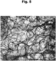
- the loop diameter (loop diameter) is expediently measured as follows: The nonwoven fabric to be measured is placed under a microscope and a still image is generated using a suitable magnification and the loop diameter (loop diameter) can be measured therein. For example, the in Fig. 5 shown image taken using a "5x" lens of an Olympus BX51 microscope with a USB camera.
- the optical system In the case of spun-bonded nonwoven laminates with several layers, the optical system must be focused on the surface of each visible layer, so that the further surfaces or layers lie as far as possible outside of the depth of field. Due to the random distribution of the filaments and the random distribution of the loop diameters, at least 25 measurements are required. The arithmetic mean is given.
- the degree of crimping of the spunbond layers (with crimped filaments) arranged one above the other increases from bottom to top.
- the spunbonded nonwoven laminate according to the invention has at least three spunbonded nonwoven layers with crimped filaments, at least two lower spunbonded nonwoven layers having a degree of crimp that increases from bottom to top, while the at least one upper spunbonded layer again has a lower degree of crimp than the middle spunbonded layer.
- meltblown layers made of meltblown filaments and / or spunbonded layers made of non-crimped filaments can also be arranged in the spunbond laminate according to the invention between the spunbond layers with crimped filaments.
- Such a laminate can then, for example, consist of three layers of spunbonded fabric with crimped filaments and two Layers of meltblown fleece consist of non-crimped filaments (e.g. in SSMMS or also in SMMSS arrangement).
- the spunbonded nonwoven laminate according to the invention only has spunbonded layers with crimped filaments.
- the crimped filaments of the spunbonded nonwoven layers are designed as multicomponent filaments, in particular as bicomponent filaments, with a first and a second plastic component. It is within the scope of the invention that the crimped multicomponent filaments or the crimped bicomponent filaments have a side-by-side configuration and / or an acentric core-sheath configuration. In principle, other crimpable configurations of multi-component filaments or bicomponent filaments can also be used (e.g. island-inthe-sea).
- the melt flow rate of a first component of the bicomponent filaments or multicomponent filaments is 1.05 to 3 times, preferably 1.2 to 1.5 times larger than the melt flow rate of a second component and the molecular weight distribution (M w / M n or M z / M w ) of the first component is narrower than the molecular weight distribution of the second component and the molecular weight distribution or the M w / M n value or the M z / M w value of the second component is at least 1, 1 times larger than that of the first component.
- the first plastic component has a first plastic or the first plastic component consists of at least one first plastic and the second plastic component is a mixture or blend of at least one second plastic and at least one third plastic.
- the mass ratio of the first plastic component to the second plastic component is advantageously 50:50 to 95: 5, preferably 50:50 to 90:10, in particular 60:40 to 90:10 and very preferably 70:30 to 80:20.
- the second plastic component has or is a mixture or blend of at least one second plastic and at least one third plastic.
- the molecular weight distribution of the third plastic is wider than the molecular weight distribution of the first plastic and / or wider than the molecular weight distribution of the second plastic.
- the molecular weight distribution of the third plastic is both wider than the molecular weight distribution of the first plastic and wider than the molecular weight distribution of the second plastic. The molecular weight distribution is measured in particular according to ASTM D1238-13.
- a preferred embodiment of the invention is characterized in that the at least one first plastic and / or the at least one second plastic and / or the at least one third plastic is a polyolefin or a homo-polyolefin and / or a polyolefin copolymer.
- a very particularly recommended embodiment which is of particular importance in the context of the invention, is characterized in that the first plastic and / or the second plastic and / or the third plastic is a polypropylene or a homo-polypropylene and / or a polypropylene. Is copolymer.
- both the first plastic and the second plastic and also the third plastic is a polypropylene (homo-polypropylene) and / or a polypropylene copolymer and / or a mixture of a polypropylene (homo-polypropylene) and a polypropylene copolymer.
- the aforementioned molecular weight distributions of the plastics are preferably implemented.
- the second plastic component has a mixture or a blend of at least one second plastic and at least one third plastic.
- the proportion of the third plastic - based on the entire filament - is less than 25% by weight.
- melt flow rate (MFR) of the first component is 1.0 or 1.05 to 3 times, preferably 1.2 to 1.5 times greater than the melt flow rate of the second component.
- the melt flow rate of the first plastic component is expediently higher than the melt flow rate of a mixture or a blend of the second and the third plastic (second plastic component).
- the melt flow rate of the first plastic component is expediently at least 20% higher than the melt flow rate of the mixture or blend of the second and the third plastic.
- melt flow rate is measured in particular according to ASTM D1238-13 (condition B, 2.16 kg, 230 ° C.), specifically in grams of the polymer per 10 minutes (g / 10 min.).
- the melt flow rate of blends or blends determined by measuring the melt flow rate of the polypropylene and using a logarithmic calculation to calculate the melt flow rate of the blend.
- the spunbond nonwoven laminate according to the invention is a laminate that has been consolidated by calendering.
- a calender strengthening with a calender temperature between 100 and 160 ° C., preferably between 110 and 150 ° C. is preferably carried out.
- a recommended embodiment of the spunbonded nonwoven laminate according to the invention is characterized in that the laminate has a thickness of 0.1 to 0.9 mm, preferably 0.15 to 0.85 mm, preferably 0.2 to 0.8 mm and according to an embodiment of the Invention of 0.3 to 0.6 mm.
- a very proven embodiment of the invention is characterized in that the spunbond nonwoven laminate according to the invention has a specific thickness of 0.6 to 3.2 mm / 100 gsm, preferably a specific thickness of 0.8 to 3 mm / 100 gsm and very preferably a specific one Has a thickness of 1.0 to 2.8 mm / 100 gsm.
- the abbreviation gsm stands for g / m 2 .
- the fineness (titer) of the crimped filaments in the laminate is 0.7 to 3.2 den, preferably 0.8 to 3 den, and expediently in all spunbonded layers with crimped filaments. It is within the scope of the invention that the weight per unit area of the spunbond laminate according to the invention is between 10 and 50 g / m 2 and preferably between 10 and 40 g / m 2 .
- the filaments used in the invention can be round in cross section, be triangular or rectangular.
- the crimped filaments can be designed to be void-free or essentially void-free or can also be designed as hollow fibers.
- the invention relates to a method for producing a laminate with a plurality of spunbond layers arranged one above the other, at least two and a maximum of four of these spunbond layers being produced with or from crimped continuous filaments with the proviso that the degree of crimp of the continuous filaments in these spunbond layers is different, the crimped filaments of the spunbonded layers being produced as multicomponent filaments, in particular as bicomponent filaments, with a first plastic component and a second plastic component, each of these two components being present in the respective filament to at least 10% by weight, preferably to at least 15% by weight is wherein for the filaments at least one spunbond layer with crimped filaments, preferably a plurality of spunbond layers with crimped filaments and preferably all spunbond layers with crimped filaments, the proportion or composition of the first plastic component and / or the second plastic component in process operation (online) is set to vary the degree of
- Setting in process mode or online setting initially means in particular that the process mode for setting the component parts or the plastic parts is not interrupted and the setting of the component parts or plastic parts thus takes place during ongoing process operation and preferably takes place continuously.
- a metering device in particular a metering screw and / or metering pump and / or a spinning pump - is assigned to the plastic components or the plastics for the spunbonded nonwoven layers made of crimped filaments, and the component supply or plastic supply is varied by at least one metering device during operation (online) , in particular by changing the speed of the metering device. Because of this possibility of variation, the degree of crimping of a spunbonded nonwoven layer can be varied virtually freely in online operation and, for example, can be changed from a low degree of crimping to a high degree of crimping.
- the multi-beam system used for producing the spunbonded nonwoven laminate is expedient for the multi-beam system used for producing the spunbonded nonwoven laminate to be simultaneously or simultaneously varied on all spinning beams or spinnerets simultaneously. As a result, waste material in particular can be effectively minimized.
- the proportion or the composition of the plastic components or in particular the second plastic component is varied by setting at least one metering device for the plastic components or for the second plastic component in process operation (online), preferably as a function of the properties or Parameters of the spunbonded nonwoven layer produced thereby, the control of the metering device or the metering devices by means of hardware and / or software components being carried out, according to a preferred embodiment variant, taking place automatically as a function of determined or measured properties of the spunbonded layer produced therewith.
- composition of the plastic components or the second plastic component online by setting at least one, preferably one, metering device for the plastic components or for the second plastic and / or by setting at least one, preferably one, metering device for the plastic components or for the third plastic of the second plastic component, and recommended to the one described above Way.
- the dosing device is a dosing screw and / or dosing pump and the setting is preferably carried out by changing the speed of a dosing screw. It is recommended above all that the online setting of the composition of the plastic components or in particular the second plastic component described above is possible on all spinning beams or spinnerettes of the multi-beam system or is carried out on all spinning beams or spinnerets of the multi-beam system.
- a spinning pump is connected downstream of the extruder for each plastic component as a metering device for this plastic component.
- the metering device or metering pump means a spinning pump or also a spinning pump. It is therefore within the scope of the invention that the mass throughput of the individual plastic components of the bicomponent filaments or multicomponent filaments is set online or in process operation on at least one spinning pump, expediently by varying the speed of the respective spinning pump.
- an extruder is expediently used for the plastic components of the bicomponent filaments or multicomponent filaments to be produced. It is recommended that each of these extruders is followed by a spinning pump for the respective plastic component as a metering device, and by adjusting the spinning pump or the speed of the spinning pump, the amount of the plastic component fed in and thus the composition of the bicomponent filaments or multicomponent filaments can be adjusted online or in process operation.
- At least one plastic component (in particular the second plastic component) of the bicomponent or multicomponent filaments is designed as a plastic blend, this plastic blend comprising a main plastic (in particular a second plastic) and at least one secondary plastic (in particular a third plastic).
- the extruder for the respective plastic component here in particular the second plastic component
- a metering device - in particular in the form of a metering screw - for each secondary plastic.
- the composition of the second plastic component can be varied online by setting this metering device or metering screw in process operation.
- the invention is based on the knowledge that it is advantageous to work with the same raw material (plastic) or with the same type of raw material (type of plastic) for the rapid variation of the degree of crimping, a spunbonded layer or for the rapid change from one filament composition to another filament composition and that especially polyolefins, in particular polypropylenes, and especially the polyolefins or polypropylenes with the properties highlighted here are suitable for this.
- the optimization or the variation of the degree of crimp can then be special can be realized simply by changing the component proportions of the filaments of a spunbonded nonwoven layer or by changing the proportions of a plastic mixture or a plastic blend used.
- the first plastic component of the crimping filaments of a spunbonded nonwoven layer is produced from at least one first plastic and that the second plastic component of the crimping filaments of a spunbonded nonwoven layer is produced from at least one second plastic and at least one third plastic.
- the proportion of the third plastic in process operation can be adjusted or adjusted to vary the degree of crimping of the respective spunbonded layer.
- the proportion of the second plastic and the third plastic is expediently varied in process operation (online).
- the second plastic and / or the third plastic is a polyolefin, in particular a polypropylene.
- polyolefin in particular polypropylene
- a particularly simple and reliable online variation of the proportion of the second plastic and / or the proportion of the third plastic of the filaments of a crimped spunbonded nonwoven layer can take place.
- the laminate is solidified by calendering in at least one calender.
- the invention is based on the knowledge that the online variation according to the invention of the plastic component portion or the plastic portion of the crimped filaments of a spunbonded nonwoven layer can be used particularly effectively to obtain a spunbond laminate from the individual set spunbond layers, which can be transferred from a deposit or from a deposit belt to a calender in a simple and functionally reliable manner, in particular without a large or too large speed difference in the speeds the deposit belt on the one hand and the calender rolls on the other.
- the spunbonded nonwoven laminate is transferred from a depositing device, preferably from a depositing screen belt to a calender, and that the speed of the depositing device or the depositing screen belt is lower than the surface speed of the calender rolls and that the surface speed of the calender rolls is a maximum of 8%. , preferably by a maximum of 5% greater than the speed of the depositing device or the depositing screen belt.
- a depositing device preferably from a depositing screen belt to a calender
- the speed of the depositing device or the depositing screen belt is lower than the surface speed of the calender rolls and that the surface speed of the calender rolls is a maximum of 8%. , preferably by a maximum of 5% greater than the speed of the depositing device or the depositing screen belt.
- the invention also relates to a device for producing a spunbond nonwoven laminate with a plurality of spunbond nonwoven layers arranged one above the other, at least two and a maximum of four spunbond nonwoven layers having crimped continuous filaments or consisting of crimped continuous filaments, wherein the device has a plurality of spinning beams or spinnerettes arranged one behind the other, one with at least some of the spinning beams - in particular with two to four spinning beams Spunbonded layer with / can be produced from crimped multicomponent filaments, in particular bicomponent filaments, at least one, preferably one, extruder is assigned to a spinning beam for each plastic component of the crimped multicomponent filaments or bicomponent filaments, with which the plastic component can be fed to the spinning beam or the spinneret and wherein each extruder is assigned at least one metering device with which the amount and / or the composition of at least one plastic component can be varied (online) during operation of the device.
- At least one dosing device is connected upstream of at least one extruder - in particular in the form of at least one dosing screw - and with this dosing device or dosing screw the composition of the plastic component fed to the extruder or the amount of plastic mixture components fed to the extruder during operation of the device (online) variable. It is also within the scope of the invention that at least one dosing device - in particular in the form of a spinning pump - is connected downstream of at least one extruder and that the amount of the plastic component fed to the spinning beam or the spinnerette can be varied (online) with this dosing device during operation of the device is.
- At least one spinning beam is, on the one hand, at least one extruder or an extruder for feeding a first plastic component from a first Assigned plastic and on the other hand at least one, preferably a second extruder for feeding a second plastic component, in particular in the form of a blend of a second and a third plastic, two metering devices being connected upstream of the second extruder for the blend, one metering device for the second plastic component and the second metering device is provided for the third plastic component and wherein the metering device for the second plastic and / or the metering device for the third plastic can be controlled and / or regulated (online) during operation of the device by the amount or the proportion of the to vary the second plastic and / or the third plastic in the blend and thus in the multicomponent filaments or bicomponent filaments (online).
- At least one or one spinning pump is assigned or connected to each extruder of a spinning beam, and by setting the spinning pumps online, the mass ratio between the plastic components of the multicomponent filaments or bicomponent filaments and in particular the mass ratio between a first component and a second component of the bicomponent filaments is online or is adjustable in process operation.
- This mass ratio of a first plastic component to a second plastic component of crimpable bicomponent filaments is preferably 70:30 to 90:10 or 50:50 to 80:20 in the context of the invention.
- the following device is used for producing a spunbonded nonwoven layer from crimped continuous filaments by means of a spinning beam:
- the continuous filaments are spun in the form of multicomponent filaments, in particular bicomponent filaments, and then by a cooling device for cooling of filaments guided.
- a monomer suction device is arranged between the spinning beam and the cooling device, with which suction takes place from the filament formation space directly under the spinning beam, so that in addition to air, the gases generated during the spinning of the filaments in the form of decomposition products, monomers, oligomers and the like the system can be removed.
- the filament curtain produced by the spinning beam is preferably subjected to cooling air from opposite sides.
- a recommended embodiment is characterized in that the cooling device is divided into at least two cooling chamber sections arranged one behind the other in the flow direction of the filaments, in which process air of different temperatures can be supplied.
- a stretching device connects behind or below the cooling device, with which the filaments passing through the cooling device are drawn or stretched.
- An intermediate channel expediently adjoins the cooling device, which is preferably designed to converge towards the filament deposit or converges in a wedge shape.
- the filament curtain preferably enters a lower channel of the drawing device.
- a recommended embodiment of the invention which is of very special importance, is characterized in that the unit from the cooling device and the stretching device or the unit from the cooling device and the intermediate channel and the lower channel is designed as a closed unit. Closed unit here means that apart from the supply of process air or cooling air in the cooling device, there is no further air supply into this unit and the unit is thus designed to be closed to the outside.
- the continuous filaments emerging from the stretching device be passed through a laying unit which has at least one diffuser.
- at least two diffusers arranged one behind the other are provided.
- the filaments are expediently placed on a depositing device, which is preferably designed as a depositing screen belt.
- the filaments for the nonwoven web or for the spunbonded layer are deposited there.
- the filing belt is designed as an endless belt.
- the nonwoven web or the spunbonded nonwoven layer can be deposited on this deposit screen belt on at least one spunbonded nonwoven layer already formed with another spinning beam, so that a spunbonded nonwoven laminate is formed in this way.
- process air is drawn off through the depositing screen belt in a suction area.
- a plurality of suction areas can also be arranged one behind the other in the conveying direction of the nonwoven web.
- the invention is based on the knowledge that with the method according to the invention and with the device according to the invention, spunbond laminates with a high thickness and high volume can be produced with different degrees of crimping of the spunbond layers in a simple, reliable and inexpensive manner.
- a high degree of uniformity or homogeneity and stability of the individual spunbonded layers can be achieved. It is essential that the stability and strength of the entire spunbond laminate can be set and guaranteed in a simple and expeditious manner, so that it can be transferred from a deposit screen belt to a consolidation device, in particular to a calender, without disturbing interference.
- the transfer to the calender can be advantageously less There is a speed difference between the depositing belt and the calender rolls.
- the invention is further based on the knowledge that these considerable advantages can be achieved by simply setting the filament compositions of the individual spunbond layers online, by adapting them to the desired results at short notice and continuously. Furthermore, the invention is based on the finding that such a rapid online change from one filament composition to another filament composition for a spunbonded nonwoven layer can be achieved particularly easily if the same raw material is used for the individual filament components and this is only due to different individual parameter properties distinguished. In particular, the invention is based on the finding that particularly good results are achieved when the filament compositions are adjusted online, if with polyolefins and in particular with polypropylenes or polypropylene copolymers for the individual filament components or with corresponding mixtures / blends of these plastics for a filament component is worked.
- spunbond devices in the form of multi-beam systems can be converted into devices according to the invention in a simple manner.
- the spunbonded nonwoven laminates according to the invention are particularly suitable as products in the hygiene sector, but can in principle also be used for other fields of application.
- spunbond layers or spunbond laminates were produced from crimped bicomponent filaments made from polypropylenes.
- the first plastic component of the bicomponent filaments consisted of a polypropylene component PP1 and the second plastic component either only from a polypropylene component PP2 or from a mixture or blend of polypropylene components PP2 and PP3.
- PP1 polypropylene component
- PP2 polypropylene component
- PP3 polypropylene component
- the extruder for the second plastic component was preceded by two dosing screws, each of which was intended for the polypropylene component PP2 or for the polypropylene component PP3.
- the speed of the two dosing screws could be varied online or in process mode without switching off the device.
- a spunbond layer (spunbond layer) was produced from crimped bicomponent filaments with side-by-side configuration and round filament cross-section from polypropylenes.
- the continuous online adjustment of the filament composition according to the invention was carried out on the layer.
- the mass ratio of the first plastic component (polypropylene component PP1) to the second plastic component (blend of polypropylene components PP2 and PP3) was 70:30.
- the bicomponent filaments were produced with a filament fineness of 1.7 to 1.8 den.
- the spunbonded nonwoven layers were each consolidated with a calender at a calender surface temperature of 140 ° C., namely with an embossing surface of 12% with round consolidation elevations in a density of 25 fig / cm 2 .
- a homo-polypropylene (PP1) with a melt flow rate (MFR) of about 35 g / 10 min was used as the first plastic component of the bicomponent filaments.
- Homo-polypropylene "Exxon 3155" was used for the first plastic component.
- the bicomponent filaments a blend (mixture) of a homo-polypropylene (PP2) and another homo-polypropylene (PP3) was used, both homo-polypropylenes having a melt flow rate (MFR) of about 25 g / 10 min. and the molecular weight distribution (MWD) of PP3 was wider than that of PP2.
- MFR melt flow rate
- MWD molecular weight distribution
- PP combination A The filament composition mentioned is referred to here and below as PP combination A.
- bicomponent filaments were used to produce crimped spunbond layers with a basis weight of 25 gsm.
- the proportion of PP3 in the blend of the second plastic component was varied from 0 to 45% PP3 during ongoing process operation.
- the speed of the two dosing screws for PP3 and PP2 upstream of the extruder for the second plastic component was changed accordingly online.
- the mass ratio 70:30 between the first and second plastic components remained unchanged.
- the speed increase specified in the tables also relates to the speed increase from the depositing screen belt to the calender rolls, which is required for a functionally reliable transfer of the layer.
- the two tables show that an increased proportion of PP3 generally results in a higher layer thickness and a lower secant modulus leads to a higher speed increase between the deposit screen belt and the calender.
- Table 1 PP combination A
- a higher PP3 content leads to a stronger crimp.
- the number of loops or loops increases with the PP3 component and the crimp diameter (loop diameter) decreases accordingly with the PP3 component.
- a PP3 content of 45% does not always lead to an increased thickness compared to a PP3 content of 30%. It seems appropriate to choose the maximum percentage of PP3 as 50%.
- a spunbond layer (spunbond layer) was produced from crimped bicomponent filaments with side-by-side configuration and round filament cross-section from polypropylenes.
- a continuous online adjustment of the filament composition according to the invention was carried out on the layer, specifically the mass ratio of the first plastic component (polypropylene component PP1) to the second plastic component (polypropylene component PP2) was changed online.
- the mass throughput and the speeds of the two extruders for the two plastic components were connected Spinning pumps in process operation or online varies (see Fig. 2b with reference numerals P1 and P2 for the two spinning pumps).
- Example 1 only one spinning beam was used and bicomponent filaments with a filament fineness of about 1.7 den were spun.
- the spunbonded nonwoven layers were each consolidated with a calender according to the specification in Example 1, in this case with a calender surface temperature of 130 ° C.
- Spunbonded layers with a basis weight of 20 gsm were produced, specifically at a production speed of 125 m / min.
- the first plastic component of the bicomponent filaments was a homo-polypropylene (PP1) with a melt flow rate (MFR) of about 25 g / 10 min.
- MFR melt flow rate
- the homo-polypropylene "Basell Moplen HP 561R" was used for the first plastic component.
- no blend was used as the second plastic component of the bicomponent filaments, but only a plastic in the form of a statistical polypropylene copolymer with a melt flow rate (MFR) of about 30 g / 10 min.
- the polypropylene copolymer "Basell Moplen RP 248 R” was used here for the second plastic component.
- the melting point difference between the first plastic component (PP1) and the second plastic component (PP2) was 12 ° C.
- the mass ratio of the two plastic components was changed online or in process operation by varying the throughput of the two spinning pumps. Table 3 below shows the amount of the first plastic component (PP1) in percent.
- the melting point of the plastics or polymers is measured by DSC according to ISO 11357-3.
- the thickness of the spunbonded nonwoven layer is greatest.
- An optimal compromise between the thickness and the increase in speed results here in particular for example no. 10. Since, in this exemplary embodiment, no blend is used for the second plastic component, it is not necessary to use two metering screws in front of an extruder.
- the online variation of the proportion of the two plastic components (PP1, PP2) only takes place by changing the speed of the two spinning pumps for the two plastic components.
- Three-layer spunbond nonwoven laminates were produced from crimped bicomponent filaments using a spunbond device with three spinning beams (see also Figures 1 and 2nd ). In each case, the laminate was calendered with the calender parameters according to exemplary embodiment 1.
- the spunbonded nonwoven laminates were each produced with a basis weight of 25 gsm at a production speed of 400 m / minutes.
- Each line or number in Table 4 below corresponds to a three-layer spunbond laminate.
- the spunbond laminates according to numbers 17 and 18 use the PP combinations A and B specified above for all three spunbond layers.
- the first plastic component corresponds to the homo-polypropylene PP1 from the PP combination A (MFR of about 35 g / 10 min., "Exxon 3155") and also in the blend (mixture) of the second plastic component as Homo-polypropylene PP2 uses this plastic "Exxon 3155".
- another homo-polypropylene PP3 of the blend of the second plastic component is a homo-polypropylene with a melt flow rate of 13 g / 10 min. used with a broad molecular weight distribution (“Basell Moplen HP552N").
- Baseell Moplen HP552N broad molecular weight distribution
- the molecular weight distribution of this homopolypropylene PP3 is again broader than the molecular weight distribution of homopolypropylene PP2 and also that of PP2 homopolypropylene identical.
- the mass ratio of the first plastic component to the second plastic component of the bicomponent filaments is given in Table 4 below and, on the other hand, the proportion of homopolypropylene PP3 in the blend of the second plastic component.
- Table 4 Three-layer spunbond laminates with PP combinations A, B and C: ⁇ /u> No. PP combination Mass ratio of components 1: 2 PP3 amount [%] Bar 1 Bar 2 Bar 3 Bar 1 Bar 2 Bar 3 15 C. 80:20 70:30 70:30 25th 25th 25th 16 C.
- the loop diameters in Table 4 show that the lower layer produced with the first spinning beam has a larger loop diameter than the uppermost layer produced with the third spinning beam and thus also as the middle layer that corresponds to the uppermost layer the amount of plastic used is identical. This results in a change in the degree of crimp or a crimp gradient "low” / "high” / "high” (from the bottom to the top layer) for the three layers of all four spunbond laminates.
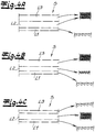
- Such a spunbond laminate is, for example, in the Figure 4a shown. This corresponds to the preferred embodiment of the invention, according to which the degree of crimp in the spunbonded nonwoven laminate should increase from bottom to top.
- the loop diameter of the lowest layer is significantly smaller in Example No. 15 than in Example No. 16.
- This greater crimp is in Example No. 15 attributable to the higher mass fraction of the second component (20% by weight) in the bicomponent filaments of the first spinning beam.
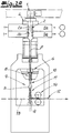
- the Fig. 1 shows an inventive device for producing a spunbond laminate S, which preferably and in the exemplary embodiment has three spunbond layers L1, L2 and L3. Corresponding to the three spunbond layers L1, L2 and L3, three spinning beams or spinnerettes 1 are provided, from which filaments 3 in the form of bicomponent filaments are preferably spun and in the exemplary embodiment.
- the filaments 3 of each spunbond layer L1, L2 and L3 are deposited after passing through a diffuser 11 on a deposit screen belt 13 to the spunbond layer L1, L2 and L3.
- Each spunbond layer L1, L2, L3 is compacted with a pair of compacting rollers 14.
- the finished three-layer spunbond laminate S is then transferred from the deposit screen belt 13 to a calender 17 from two calender rolls 18, 19.
- the Fig. 1 also shows an enlarged section of the transfer of the spunbonded nonwoven laminate S from the deposit screen belt 13 to the calender 17.
- the deposit screen belt 13 is moved at a speed v 1 , while the calender rolls 18, 19 rotate at a surface speed v 2 . It is within the scope of the invention that the surface speed v 2 of the Calender rolls 18, 19 is greater than the speed v 1 of the depositing screen belt 13 by a maximum of 8%, preferably by a maximum of 5%.
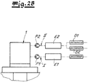
- the Fig. 2 shows part of the device according to the invention in the area of a spinning beam or in the area of a spinnerette 1.
- a spunbonded layer L1 or L2 or L3 is produced with this device part.
- the filaments 3 - preferably and in the exemplary embodiment in the form of bicomponent filaments - are spun by means of the spinnerette 1 and then guided through a cooling device 2 for cooling the filaments 3.
- a monomer suction device 4 is arranged between the spinnerette 1 and the cooling device 2, with which a suction from the filament formation space takes place directly below the spinnerette 1.
- the gases generated during the spinning of the filaments 3 in the form of decomposition products, monomers, oligomers and the like are removed from the system.
- the filament curtain led from the spinnerette 1 to the filament deposit is preferably supplied with cooling air from opposite sides.
- the cooling device 2 is divided into two cooling chamber sections 2a, 2b which are arranged one behind the other in the flow direction of the filaments 3 and in which process air of different temperatures can be supplied.
- process air at a lower temperature for example 20 ° C.
- process air or cooling air with a higher temperature for example 25 ° C.
- the cooling air is expediently supplied via air supply cabins 5a and 5b.
- a stretching device 6 connects behind or below the cooling device 2, by means of which the filaments 3 passing through the cooling device 2 are drawn or drawn.
- the intermediate channel 7, which is preferably designed to converge toward the deposition of the filaments 3 or converges in a wedge shape.
- the filament curtain expediently enters the pulling channel 8 of the stretching device 6 after the intermediate channel 7.
- the unit consisting of the cooling device 2 and the stretching device 6 is designed as a closed unit.
- a closed unit means that apart from the supply of process air or cooling air in the cooling device 2, there is no further air supply into this unit and the unit is thus designed to be closed to the outside.
- Such a closed unit is expediently implemented in the device according to the invention for all parts of the device with spinning beams or spinnerets 1 for producing crimped filaments 3.
- the filaments 3 emerging from the stretching device 6 are preferably passed through a laying unit 9 which has at least one diffuser 10, 11.
- a laying unit 9 which has at least one diffuser 10, 11.
- two diffusers 10, 11 arranged one behind the other are provided.
- the filaments 3 are recommended and, in the exemplary embodiment, deposited on the depositing device or on the depositing screen belt 13 to the nonwoven web 12 or to the spunbonded nonwoven layer L1 or L2 or L3.
- the deposit screen belt 13 is preferably designed as an endless belt.
- process air is drawn off through the deposit screen belt 13 in the deposit area of the filaments 3 or the nonwoven web 12, which in the Figure 1 and 2a is indicated by the arrow A.
- the deposited nonwoven web 12 or the deposited spunbonded nonwoven layer L1, L2 or L3 is first guided with the deposit screen belt through the gap of a pair of compacting rollers 14 for compacting.
- Fig. 1 indicated the spunbond laminate S formed from the spunbond nonwoven layers L1, L2, L3 for consolidation by a calender 17 out of calender rolls 18, 19.
- Plastic component II is a blend (mixture) of plastics and, according to the recommended embodiment, of polypropylene.
- the extruder E2 assigned to this plastic component II is preceded by two metering screws D1 and D2, one of the two plastics of the blend being fed to the extruder E2 with each metering screw D1 and D2.
- the rotational speed of the metering screws D1 and / or D2 can be controlled and / or regulated online or in process operation without switching off the device.
- Fig. 3 Typical cross sections for bicomponent filaments are shown, which are preferably produced using the method according to the invention or using the device according to the invention. With these filament cross sections of the bicomponent filaments, crimped filaments 3 can be produced.
- Fig. 3a a typical side-by-side configuration of crimpable bicomponent filaments is shown. A plastic component I or II is arranged on each side of this filament cross section.
- the Fig. 3b shows an acentric core-sheath configuration for crimpable bicomponent filaments.
- Fig. 3c shows a trilobal cross section for crimpable bicomponent filaments.
- the shows Fig. 3d an internally hollow filament 3 with side-by-side configuration. All of these filament cross-sections are suitable for the production of crimpable bicomponent filaments.
- Fig. 4 Three spunbond nonwoven laminates S which can be produced using the method according to the invention are shown.
- the bottom spunbond layer L1 has the least crimp and the middle spunbond layer L2, on the other hand, has a higher crimp.
- the degree of crimp increases from bottom to top in the spunbond laminate S.
- a ripple order "low” / "high” / "high” can be observed, while in the example after Fig. 4b a "low” / "medium” / "high” crimping order can be observed from bottom to top.
- the embodiment according to Fig. 4c finally shows a crimp order "low” / "high” / "low”.
Description
Die Erfindung betrifft ein Spinnvlieslaminat mit einer Mehrzahl von übereinander angeordneten Spinnvlieslagen, wobei Spinnvlieslagen gekräuselte Endlosfilamente aufweisen bzw. aus gekräuselten Endlosfilamenten bestehen. Die Erfindung bezieht sich fernerhin auf ein Verfahren sowie auf eine Vorrichtung zur Erzeugung eines solchen Spinnvlieslaminates. - Spinnvlies meint im Rahmen der Erfindung insbesondere ein nach dem Spunbond-Verfahren hergestelltes Spunbond-Vlies. Endlosfilamente unterscheiden sich aufgrund ihrer quasi endlosen Länge von Stapelfasern, die viel geringere Längen von beispielsweise 10 mm bis 60 mm aufweisen. Bei den im Rahmen der Erfindung eingesetzten Endlosfilamenten handelt es sich insbesondere um Endlosfilamente aus thermoplastischem Kunststoff.The invention relates to a spunbonded nonwoven laminate with a plurality of spunbonded nonwoven layers arranged one above the other, wherein spunbonded nonwoven layers have crimped continuous filaments or consist of crimped continuous filaments. The invention further relates to a method and an apparatus for producing such a spunbond nonwoven laminate. - Spunbond means in the context of the invention in particular a spunbond nonwoven manufactured by the spunbond process. Due to their quasi-endless length, continuous filaments differ from staple fibers, which have much shorter lengths of, for example, 10 mm to 60 mm. The continuous filaments used in the context of the invention are, in particular, continuous filaments made of thermoplastic material.
Spinnvlieslaminate der vorstehend genannten Art sind aus der Praxis grundsätzlich in verschiedenen Ausführungsformen bekannt. - Bei den bekannten Spinnvliesen treten häufig Probleme auf, wenn ein Spinnvlies einerseits mit geringem Flächengewicht und andererseits mit großer Dicke bzw. hohem Volumen hergestellt werden soll. Hohe Dicken werden in der Regel durch einen hohen Kräuselungsgrad der Filamente erzielt. Dadurch entsteht aber ein relativ anfälliges Aggregat in Bezug auf mechanische Einflüsse bzw. Kräfte. So neigen die stark gekräuselten Fasern bei mechanischen Einwirkungen zum Öffnen der Kräuselschlaufen. Dann kann ein nachteilhaft inhomogenes Vlies resultieren. - Vliese bzw. Vlieslaminate werden normalerweise auf einem Ablageband abgelegt und von diesem Ablageband an einen Kalander übergeben. Die dabei auf das Vlies bzw. Vlieslaminat einwirkenden Kräfte können Verschiebungen bzw. Verzerrungen in dem Vlies bzw. an der Vliesoberfläche hervorrufen, so dass eine unerwünschte Inhomogenität des Vlieses bzw. des Vlieslaminates resultiert. Deshalb müssen die Geschwindigkeiten der Ablagevorrichtung einerseits und des Kalanders andererseits aufeinander abgestimmt werden. Nichtsdestoweniger verbleibt ein Zielkonflikt zwischen einer hohen Vliesdicke bzw. Laminatdicke und einer zügigen und funktionssicheren Übergabe zwischen Ablageband und Kalander.Spunbonded laminates of the type mentioned above are known in practice in various embodiments. - Problems often arise with the known spunbonded nonwovens if a spunbonded nonwoven is to be produced on the one hand with a low basis weight and on the other hand with a large thickness or high volume. High thicknesses are usually achieved through a high degree of curling of the filaments. However, this creates a relatively vulnerable unit with regard to mechanical influences or forces. The strongly crimped fibers tend to open the crimped loops under mechanical influences. A disadvantageously inhomogeneous fleece can then result. - Nonwovens or nonwoven laminates are normally deposited on a storage belt and transferred from this storage belt to a calender. The forces acting on the nonwoven or nonwoven laminate can cause displacements or distortions in the nonwoven or on the nonwoven surface, so that an undesirable inhomogeneity of the nonwoven or nonwoven laminate results. So they have to Speeds of the storage device on the one hand and the calender on the other hand can be coordinated. Nonetheless, there remains a conflict of goals between a high fleece or laminate thickness and a quick and reliable transfer between the storage belt and the calender.
In diesem Zusammenhang tritt ein Problem insbesondere auch bei Mehrbalken-Anlagen auf, in denen beispielsweise mehrere Spunbond-Balken oder ein Spunbond-Balken, ein Meltblown-Balken und wiederum ein Spunbond-Balken hintereinander geschaltet sind. Um ein bestimmtes Flächengewicht des resultierenden Vlieslaminates einzuhalten ist man bestrebt die Flächengewichte der einzelnen Lagen zu reduzieren. Dadurch werden die Filamentlagen aber empfindlicher und zwar insbesondere auch gegenüber einer Saugluftbeaufschlagung auf dem Ablageband bzw. Ablagesiebband. Insbesondere die untere Lage eines solchen Vlieslaminates kann durch die Saugluft so beaufschlagt werden, dass Filamente in die Zwischenräume des Siebbandes eingesaugt werden. Das macht die Übergabe zwischen Ablageband und Kalander schwieriger. Um die diesbezüglichen Probleme gering zu halten wird in der Praxis die Dicke bzw. die Voluminösität der einzelnen Lagen eher reduziert und somit auch die Kräuselung reduziert.In this context, a problem arises in particular in multi-beam systems in which, for example, a plurality of spunbond beams or a spunbond beam, a meltblown beam and in turn a spunbond beam are connected in series. In order to maintain a certain basis weight of the resulting nonwoven laminate, the aim is to reduce the basis weights of the individual layers. As a result, however, the filament layers become more sensitive, and in particular also to suction air on the deposit belt or deposit screen belt. In particular, the lower layer of such a nonwoven laminate can be acted upon by the suction air in such a way that filaments are sucked into the spaces between the sieve belt. This makes the transfer between the delivery belt and the calender more difficult. In order to keep the related problems low, the thickness or the bulk of the individual layers is rather reduced in practice and thus the curl is also reduced.
Im Ergebnis mussten bei den bislang bekannten Maßnahmen zur Erzeugung relativ voluminöser Vlieslaminate unerwünschte Inhomogenitäten in Kauf genommen werden und/oder nachteilhafte Kompromisse zu Lasten der Voluminösität eingegangen werden.As a result, in the previously known measures for producing relatively voluminous nonwoven laminates, undesirable inhomogeneities had to be accepted and / or disadvantageous compromises had to be made at the expense of bulkiness.
Man hat bereits erfolgreich versucht die vorstehend genannten Probleme zu lösen (
Aus
Der Erfindung liegt das technische Problem zugrunde, ein Spinnvlieslaminat der eingangs genannten Art bzw. ein Verfahren und eine Vorrichtung zur Herstellung eines solchen Spinnvlieslaminates anzugeben, bei dem das Spinnvlieslaminat eine hohe Dicke bzw. ein hohes Volumen bei verhältnismäßig hohem Kräuselgrad der Filamente aufweist, bei dem nichtsdestoweniger eine hohe Homogenität und Stabilität der einzelnen Lagen gewährleistet ist und das insbesondere auf einfache Weise transportiert und übergeben werden kann, vor allem von einem Ablageband zu einem Kalander problemlos übergeben werden kann. Dieses Problem soll insbesondere auch für Spinnvlieslagen bzw. Spinnvlieslaminate mit geringeren Flächengewichten effektiv gelöst werden.The invention is based on the technical problem of specifying a spunbonded nonwoven laminate of the type mentioned at the outset or a method and an apparatus for producing such a spunbonded nonwoven laminate in which the spunbonded nonwoven laminate has a high thickness or a high volume with a relatively high degree of crimping of the filaments, in which nonetheless, a high degree of homogeneity and stability of the individual layers is guaranteed and that can be transported and transferred in a simple manner, in particular can be transferred without problems from a storage belt to a calender. This problem is to be solved effectively in particular for spunbonded nonwovens or spunbonded laminates with lower basis weights.
Zur Lösung dieses technischen Problems lehrt die Erfindung zunächst ein Spinnvlieslaminat mit einer Mehrzahl von übereinander angeordneten Spinnvlieslagen, wobei zumindest zwei und maximal vier Spinnvlieslagen gekräuselte Endlosfilamente aufweisen bzw. aus gekräuselten Endlosfilamenten bestehen,
wobei der Kräuselungsgrad der Filamente in diesen Spinnvlieslagen jeweils unterschiedlich ist, wobei die gekräuselten Filamente der Spinnvlieslagen jeweils eine Kräuselung mit mindestens drei und bevorzugt mit mindestens vier Schlingen (loops) pro Zentimeter ihrer Länge aufweisen,
und wobei die gekräuselten Filamente der Spinnvlieslagen als Multikomponentenfilamente, insbesondere als Bikomponentenfilamente, mit einer ersten Kunststoffkomponente und einer zweiten Kunststoffkomponente ausgebildet sind, wobei jede der beiden Kunststoffkomponenten zu mindestens 10 Gew.-%, vorzugsweise zu mindestens 15 Gew.-% in dem jeweiligen Filament vorhanden ist,
wobei der Kräuselungsgrad einer unteren Spinnvlieslage der übereinander angeordneten Spinnvlieslagen geringer ist als der Kräuselungsgrad zumindest einer darüber angeordneten Spinnvlieslage
und wobei die zweite Kunststoffkomponente eine Mischung bzw. ein Blend aus zumindest einem zweiten Kunststoff und zumindest einem dritten Kunststoff aufweist bzw. ist und wobei der Anteil des dritten Kunststoffes - bezogen auf das gesamte Filament - weniger als 25 Gew.-% beträgt.To solve this technical problem, the invention first teaches a spunbond laminate with a plurality of spunbond layers arranged one above the other, at least two and at most four spunbond layers having crimped continuous filaments or consisting of crimped continuous filaments,
the degree of crimping of the filaments in each of these spunbonded nonwoven layers being different, the crimped filaments of the spunbonded nonwoven layers each have a crimp with at least three and preferably with at least four loops per centimeter of their length,
and wherein the crimped filaments of the spunbonded layers are designed as multicomponent filaments, in particular as bicomponent filaments, with a first plastic component and a second plastic component, each of the two plastic components being at least 10% by weight, preferably at least 15% by weight in the respective filament is available,
wherein the degree of crimp of a lower spunbond layer of the spunbond layers arranged one above the other is less than the degree of crimp of at least one spunbond layer arranged above it
and wherein the second plastic component has or is a blend or a blend of at least one second plastic and at least one third plastic and wherein the proportion of the third plastic - based on the entire filament - is less than 25% by weight.
Eine ganz besonders bevorzugte Ausführungsform der Erfindung ist dadurch gekennzeichnet,
- dass die Schmelzflussrate der
ersten Komponente 1 bis 3 mal, bevorzugt 1,2 bis 1,5 mal größer ist als die Schmelzflussrate der zweiten Komponente - und/oder dass die Molekulargewichtsverteilung (Mw/Mn oder Mz/Mw) der ersten Komponente enger ist als die Molekulargewichtsverteilung der zweiten Komponente und/oder der Mw/Mn-Wert oder Mz/Mw-Wert der zweiten Komponente mindestens 1,1 mal größer ist als die/der der ersten Komponente
- und/oder dass die Schmelzpunktdifferenz zwischen der ersten und der zweiten Komponente mindestens 10 °C beträgt.
- that the melt flow rate of the first component is 1 to 3 times, preferably 1.2 to 1.5 times larger than the melt flow rate of the second component
- and / or that the molecular weight distribution (M w / M n or M z / M w ) of the first component is narrower than the molecular weight distribution of the second component and / or the M w / M n value or M z / M w value of the second component is at least 1.1 times greater than that of the first component
- and / or that the melting point difference between the first and the second component is at least 10 ° C.
Besonders bewährt hat sich im Rahmen der Erfindung eine Ausführungsform, bei der die Differenz zwischen den Flächengewichten der Spinnvlieslagen mit gekräuselten Filamenten weniger als 25 %, vorzugsweise weniger als 15 % und bevorzugt weniger als 10 % beträgt. Gemäß besonders bevorzugter Ausführungsform der Erfindung beträgt die Differenz zwischen den Flächengewichten der Spinnvlieslagen mit gekräuselten Filamenten maximal 5 % und bevorzugt sind die Flächengewichte der Spinnvlieslagen mit gekräuselten Filamenten gleich bzw. in etwa gleich.An embodiment in which the difference between the basis weights of the spunbond layers with crimped filaments is less than 25%, preferably less than 15% and preferably less than 10% has proven particularly useful. According to a particularly preferred embodiment of the invention, the difference between the basis weights of the spunbonded nonwoven layers with crimped filaments is at most 5% and the basis weights of the spunbonded nonwoven layers with crimped filaments are preferably the same or approximately the same.
In dem erfindungsgemäßen Spinnvlieslaminat werden somit zwei bis vier Spinnvlieslagen mit gekräuselten Endlosfilamenten bzw. aus gekräuselten Endlosfilamenten eingesetzt und der Kräuselungsgrad der Filamente ist zweckmäßigerweise in allen Spinnvlieslagen unterschiedlich. Dabei weisen die gekräuselten Filamente dieser Spinnvlieslagen erfindungsgemäß jeweils eine Kräuselung mit mindestens drei Schlingen (loops) pro Zentimeter ihrer Länge auf. Nach einer empfohlenen Ausgestaltung der Erfindung weisen die gekräuselten Filamente jeweils eine Kräuselung mit mindestens vier Schlingen und nach einer anderen bevorzugten Ausbildung eine Kräuselung mit mindestens fünf Schlingen pro Zentimeter ihrer Länge auf.In the spunbonded nonwoven laminate according to the invention, two to four spunbonded nonwoven layers with crimped continuous filaments or made from crimped continuous filaments are used, and the degree of crimping of the filaments is expediently different in all spunbonded nonwoven layers. According to the invention, the crimped filaments of these spunbond layers each have a crimp with at least three loops per centimeter of their length. According to a recommended embodiment of the invention, the crimped filaments each have a crimp with at least four loops and, according to another preferred embodiment, a crimp with at least five loops per centimeter of their length.
Die Anzahl der Kräuselschlingen bzw. Kräuselbögen (loops) pro Zentimeter Länge der Filamente wird dabei insbesondere nach der japanischen Norm JIS L - 1015 - 1981 gemessen, indem die Kräuselungen unter einer Vorspannung von 2 mg/den in (1/10 mm) gezählt werden, wobei die ausgestreckte Länge der Filamente zugrunde liegt. Es wird eine Empfindlichkeit von 0,05 mm verwendet, um die Anzahl der Kräuselschlingen zu bestimmen. Die Messung wird zweckmäßigerweise durchgeführt mit einem "Favimat" - Gerät der Firma TexTechno, Deutschland. Dazu wird auf die Veröffentlichung "Automatic Crimp Measurement on Staple Fibres", Denkendorf Kolloquium, "Textile Mess- und Prüftechnik", 9.11.99, Dr. Ulrich Mörschel (insbesondere S. 4,
Erfindungsgemäß ist der Kräuselungsgrad einer unteren Spinnvlieslage der übereinander angeordneten Spinnvlieslagen (mit gekräuselten Filamenten) geringer als der Kräuselungsgrad zumindest einer darüber angeordneten Spinnvlieslage. Eine empfohlene Ausführungsform zeichnet sich dadurch aus, dass bei einem Spinnvlieslaminat mit zumindest drei Spinnvlieslagen mit gekräuselten Filamenten der Kräuselungsgrad der Filamente von der untersten Spinnvlieslage (mit gekräuselten Filamenten) zu der oberen (dritten) Spinnvlieslage (mit gekräuselten Filamenten) zunimmt. Eine ganz besonders bevorzugte Ausführungsform der Erfindung ist dadurch gekennzeichnet, dass der Kräuselungsgrad aller übereinander angeordneten Spinnvlieslagen (mit gekräuselten Filamenten) von unten nach oben zunimmt. Zunahme des Kräuselungsgrades der Filamente meint im Rahmen der Erfindung insbesondere eine Zunahme der Kräuselungen pro Zentimeter Filamentlänge und/oder eine Abnahme des Kräuselungsdurchmessers bzw. Schlingendurchmessers (Loopdurchmessers). Mit anderes Worten steigt der Kräuselungsgrad mit zunehmender Schlingenanzahl (Loopanzahl) pro Zentimeter Filamentlänge und/oder mit abnehmenden Schlingendurchmesser (Loopdurchmesser) der Filamente. Der Schlingendurchmesser (Loopdurchmesser) wird dabei zweckmäßigerweise wie folgt gemessen: Der zu vermessende Vliesstoff wird unter einem Mikroskop platziert und unter Verwendung einer geeigneten Vergrößerung wird ein Standbild erzeugt und darin kann der Schlingendurchmesser (Loopdurchmesser) gemessen werden. Beispielsweise wurde die in
Bei Spinnvlieslaminaten mit mehreren Lagen muss das optische System jeweils auf die Oberfläche jeder sichtbaren Lage fokussiert werden, so dass die weiteren Oberflächen bzw. Lagen so weit wie möglich außerhalb der Tiefenschärfe liegen. Aufgrund der zufälligen Verteilung der Filamente bzw. der zufälligen Verteilung der Loopdurchmesser sind jeweils mindestens 25 Messungen erforderlich. Es wird der arithmetische Mittelwert angegeben.In the case of spun-bonded nonwoven laminates with several layers, the optical system must be focused on the surface of each visible layer, so that the further surfaces or layers lie as far as possible outside of the depth of field. Due to the random distribution of the filaments and the random distribution of the loop diameters, at least 25 measurements are required. The arithmetic mean is given.
Es wurde bereits dargelegt, dass nach einer bevorzugten Ausführungsform der Erfindung der Kräuselungsgrad der übereinander angeordneten Spinnvlieslagen (mit gekräuselten Filamenten) von unten nach oben zunimmt. Gemäß einer alternativen Ausführungsvariante der Erfindung weist das erfindungsgemäße Spinnvlieslaminat zumindest drei Spinnvlieslagen mit gekräuselten Filamenten auf, wobei zumindest zwei untere Spinnvlieslagen einen von unten nach oben ansteigenden Kräuselungsgrad aufweisen, während die zumindest eine obere Spinnvlieslage wiederum einen geringeren Kräuselungsgrad aufweist als die mittlere Spinnvlieslage. - Es liegt im Übrigen im Rahmen der Erfindung, dass in dem erfindungsgemäßen Spinnvlieslaminat zwischen den Spinnvlieslagen mit gekräuselten Filamenten auch Meltblown-Lagen aus Meltblown-Filamenten und/oder Spinnvlieslagen aus nicht gekräuselten Filamenten angeordnet sein können. Ein solches Laminat kann dann beispielsweise aus drei Lagen Spinnvlies mit gekräuselten Filamenten und zwei Lagen Meltblown-Vlies aus nicht gekräuselten Filamenten bestehen (z. B. in SSMMS- oder auch in SMMSS-Anordnung). Gemäß einer empfohlenen Ausführungsform der Erfindung weist das erfindungsgemäße Spinnvlieslaminat lediglich Spinnvlieslagen mit gekräuselten Filamenten auf.It has already been shown that, according to a preferred embodiment of the invention, the degree of crimping of the spunbond layers (with crimped filaments) arranged one above the other increases from bottom to top. According to an alternative embodiment variant of the invention, the spunbonded nonwoven laminate according to the invention has at least three spunbonded nonwoven layers with crimped filaments, at least two lower spunbonded nonwoven layers having a degree of crimp that increases from bottom to top, while the at least one upper spunbonded layer again has a lower degree of crimp than the middle spunbonded layer. It is moreover within the scope of the invention that meltblown layers made of meltblown filaments and / or spunbonded layers made of non-crimped filaments can also be arranged in the spunbond laminate according to the invention between the spunbond layers with crimped filaments. Such a laminate can then, for example, consist of three layers of spunbonded fabric with crimped filaments and two Layers of meltblown fleece consist of non-crimped filaments (e.g. in SSMMS or also in SMMSS arrangement). According to a recommended embodiment of the invention, the spunbonded nonwoven laminate according to the invention only has spunbonded layers with crimped filaments.
Erfindungsgemäß sind die gekräuselten Filamente der Spinnvlieslagen als Multikomponentenfilamente, insbesondere als Bikomponentenfilamente, mit einer ersten und einer zweiten Kunststoffkomponente ausgebildet. - Es liegt im Rahmen der Erfindung, dass die gekräuselten Multikomponentenfilamente bzw. die gekräuselten Bikomponentenfilamente eine side-by-side-Konfiguration aufweisen und/oder eine azentrische Kern-Mantel-Konfiguration. Grundsätzlich können auch andere kräuselbare Konfigurationen von Multikomponentenfilamenten bzw. Bikomponentenfilamenten eingesetzt werden (z. B. island-inthe-sea). - Nach sehr bevorzugter Ausführungsform der Erfindung ist die Schmelzflussrate einer ersten Komponente der Bikomponenenfilamente bzw. Multikomponentenfilamente zum einen 1,05 bis 3 mal, bevorzugt 1,2 bis 1,5 mal größer als die Schmelzflussrate einer zweiten Komponente und die Molekulargewichtsverteilung (Mw/Mn oder Mz/Mw) der ersten Komponente ist enger als die Molekulargewichtsverteilung der zweiten Komponente und dabei ist die Molekulargewichtsverteilung bzw. der Mw/Mn-Wert oder der Mz/Mw-Wert der zweiten Komponente mindestens 1,1 mal größer als der der ersten Komponente.According to the invention, the crimped filaments of the spunbonded nonwoven layers are designed as multicomponent filaments, in particular as bicomponent filaments, with a first and a second plastic component. It is within the scope of the invention that the crimped multicomponent filaments or the crimped bicomponent filaments have a side-by-side configuration and / or an acentric core-sheath configuration. In principle, other crimpable configurations of multi-component filaments or bicomponent filaments can also be used (e.g. island-inthe-sea). - According to a very preferred embodiment of the invention, the melt flow rate of a first component of the bicomponent filaments or multicomponent filaments is 1.05 to 3 times, preferably 1.2 to 1.5 times larger than the melt flow rate of a second component and the molecular weight distribution (M w / M n or M z / M w ) of the first component is narrower than the molecular weight distribution of the second component and the molecular weight distribution or the M w / M n value or the M z / M w value of the second component is at least 1, 1 times larger than that of the first component.
Erfindungsgemäß weist die erste Kunststoffkomponente einen ersten Kunststoff auf bzw. besteht die erste Kunststoffkomponente aus zumindest einem ersten Kunststoff und die zweite Kunststoffkomponente ist eine Mischung bzw. ein Blend aus zumindest einem zweiten Kunststoff und zumindest einem dritten Kunststoff. - Das Massenverhältnis der ersten Kunststoffkomponente zur zweiten Kunststoffkomponente beträgt zweckmäßigerweise 50:50 bis 95:5, vorzugsweise 50:50 bis 90:10, insbesondere 60:40 bis 90:10 und sehr bevorzugt 70:30 bis 80:20.According to the invention, the first plastic component has a first plastic or the first plastic component consists of at least one first plastic and the second plastic component is a mixture or blend of at least one second plastic and at least one third plastic. The mass ratio of the first plastic component to the second plastic component is advantageously 50:50 to 95: 5, preferably 50:50 to 90:10, in particular 60:40 to 90:10 and very preferably 70:30 to 80:20.
Es liegt im Rahmen der Erfindung, dass die zweite Kunststoffkomponente eine Mischung bzw. ein Blend aus zumindest einem zweiten Kunststoff und zumindest einem dritten Kunststoff aufweist bzw. ist. Nach besonders bevorzugter Ausführungsform der Erfindung ist dabei die Molekulargewichtsverteilung des dritten Kunststoffes breiter als die Molekulargewichtsverteilung des ersten Kunststoffes und/oder breiter als die Molekulargewichtsverteilung des zweiten Kunststoffes. Gemäß einer Ausführungsvariante ist die Molekulargewichtsverteilung des dritten Kunststoffes sowohl breiter als die Molekulargewichtsverteilung des ersten Kunststoffes als auch breiter als die Molekulargewichtsverteilung des zweiten Kunststoffes. Die Molekulargewichtsverteilung wird insbesondere nach ASTM D1238-13 gemessen.It is within the scope of the invention that the second plastic component has or is a mixture or blend of at least one second plastic and at least one third plastic. According to a particularly preferred embodiment of the invention, the molecular weight distribution of the third plastic is wider than the molecular weight distribution of the first plastic and / or wider than the molecular weight distribution of the second plastic. According to one embodiment variant, the molecular weight distribution of the third plastic is both wider than the molecular weight distribution of the first plastic and wider than the molecular weight distribution of the second plastic. The molecular weight distribution is measured in particular according to ASTM D1238-13.
Eine bevorzugte Ausführungsform der Erfindung zeichnet sich dadurch aus, dass der zumindest eine erste Kunststoff und/oder der zumindest eine zweite Kunststoff und/oder der zumindest eine dritte Kunststoff ein Polyolefin bzw. ein Homo-Polyolefin und/oder ein Polyolefin-Copolymer ist. - Eine ganz besonders empfohlene Ausführungsform, der im Rahmen der Erfindung besondere Bedeutung zukommt, ist dadurch gekennzeichnet, dass der erste Kunststoff und/oder der zweite Kunststoff und/oder der dritte Kunststoff ein Polypropylen bzw. ein Homo-Polypropylen und/oder ein Polypropylen-Copolymer ist. Gemäß einer sehr bewährten Ausführungsform der Erfindung ist sowohl der erste Kunststoff als auch der zweite Kunststoff und auch der dritte Kunststoff ein Polypropylen (Homo-Polypropylen) und/oder ein Polypropylen-Copolymer und/oder eine Mischung aus einem Polypropylen (Homo-Polypropylen) und einem Polypropylen-Copolymer. Dabei sind vorzugsweise die vorgenannten Molekulargewichtsverteilungen der Kunststoffe realisiert. Bei Messung der Molekulargewichtsverteilungen der Polypropylen-Kunststoffe nach ASTM D1238-13 wird als Lösungsmittel für den Polypropylen-Kunststoff zweckmäßigerweise Trichlorbenzol eingesetzt und die Messung an der Lösung erfolgt bei einer Temperatur von 160 °C, wobei die Konzentration 1,5 g/l beträgt und als Sensor ein IR-Sensor eingesetzt wird. Die bei der Messung eingesetzten Säulen werden mit Polystyrol-Standards kalibriert, wobei die Messergebnisse auf "Polypropylen" umgerechnet werden und zwar unter Anwendung der Mark Houwink-Gleichung. Dabei wird zweckmäßigerweise mit folgendem Parameter-Satz gearbeitet: Polystyrol: α = 0,7 ; K = 0,0138 mL/g Polypropylen: α = 0,707 ; K = 0,0242 mL/g.A preferred embodiment of the invention is characterized in that the at least one first plastic and / or the at least one second plastic and / or the at least one third plastic is a polyolefin or a homo-polyolefin and / or a polyolefin copolymer. A very particularly recommended embodiment, which is of particular importance in the context of the invention, is characterized in that the first plastic and / or the second plastic and / or the third plastic is a polypropylene or a homo-polypropylene and / or a polypropylene. Is copolymer. According to a very proven embodiment of the invention, both the first plastic and the second plastic and also the third plastic is a polypropylene (homo-polypropylene) and / or a polypropylene copolymer and / or a mixture of a polypropylene (homo-polypropylene) and a polypropylene copolymer. The aforementioned molecular weight distributions of the plastics are preferably implemented. When measuring the Molecular weight distributions of the polypropylene plastics according to ASTM D1238-13 are expediently used as a solvent for the polypropylene plastic, and trichlorobenzene is used, and the solution is measured at a temperature of 160 ° C., the concentration being 1.5 g / l and a sensor IR sensor is used. The columns used in the measurement are calibrated using polystyrene standards, the measurement results being converted to "polypropylene" using the Mark Houwink equation. The following set of parameters is expediently used: polystyrene: α = 0.7; K = 0.0138 mL / g polypropylene: α = 0.707; K = 0.0242 mL / g.
Erfindungsgemäß weist die zweite Kunststoffkomponente eine Mischung bzw. ein Blend aus zumindest einem zweiten Kunststoff und zumindest einem dritten Kunststoff auf. Dabei beträgt der Anteil des dritten Kunststoffes - bezogen auf das gesamte Filament - weniger als 25 Gew.-%.According to the invention, the second plastic component has a mixture or a blend of at least one second plastic and at least one third plastic. The proportion of the third plastic - based on the entire filament - is less than 25% by weight.
Es liegt im Rahmen der Erfindung, dass die Schmelzflussrate (MFR) der ersten Komponente 1,0 bzw. 1,05 bis 3 mal, bevorzugt 1,2 bis 1,5 mal größer ist als die Schmelzflussrate der zweiten Komponente. Zweckmäßigerweise ist nach entsprechend bevorzugter Ausführungsform der Erfindung die Schmelzflussrate der ersten Kunststoffkomponente höher als die Schmelzflussrate einer Mischung bzw. eines Blends aus dem zweiten und dem dritten Kunststoff (zweite Kunststoffkomponente). Dabei ist die Schmelzflussrate der ersten Kunststoffkomponente zweckmäßigerweise um mindestens 20 % höher als die Schmelzflussrate der Mischung bzw. des Blends aus dem zweiten und dem dritten Kunststoff. - Im Rahmen der erfindungsgemäßen Lehre wird die Schmelzflussrate (MFR) insbesondere nach ASTM D1238-13 gemessen (Bedingung B, 2,16kg, 230°C) und zwar in Gramm des Polymers pro 10 Minuten (g/10 min.). Die Schmelzflussrate von Mischungen bzw. Blends werden bestimmt durch Messung der Schmelzflussrate des Polypropylens und durch Verwendung einer Logarithmen-Kalkulation zur Berechnung der Schmelzflussrate des Blends.It is within the scope of the invention that the melt flow rate (MFR) of the first component is 1.0 or 1.05 to 3 times, preferably 1.2 to 1.5 times greater than the melt flow rate of the second component. According to a preferred embodiment of the invention, the melt flow rate of the first plastic component is expediently higher than the melt flow rate of a mixture or a blend of the second and the third plastic (second plastic component). The melt flow rate of the first plastic component is expediently at least 20% higher than the melt flow rate of the mixture or blend of the second and the third plastic. - Within the framework of the teaching according to the invention, the melt flow rate (MFR) is measured in particular according to ASTM D1238-13 (condition B, 2.16 kg, 230 ° C.), specifically in grams of the polymer per 10 minutes (g / 10 min.). The melt flow rate of blends or blends determined by measuring the melt flow rate of the polypropylene and using a logarithmic calculation to calculate the melt flow rate of the blend.
Nach besonders bevorzugter Ausführungsform der Erfindung handelt es sich bei dem erfindungsgemäßen Spinnvlieslaminat um ein durch Kalandrieren verfestigtes Laminat. Bei dem bevorzugten Einsatz von Polyolefinen, insbesondere von Polypropylen für die Kunststoffe des Spinnvlieslaminates wird vorzugsweise eine Kalanderverfestigung mit einer Kalandertemperatur zwischen 100 und 160°C, bevorzugt zwischen 110 und 150°C durchgeführt.According to a particularly preferred embodiment of the invention, the spunbond nonwoven laminate according to the invention is a laminate that has been consolidated by calendering. In the preferred use of polyolefins, in particular polypropylene, for the plastics of the spunbond nonwoven laminate, a calender strengthening with a calender temperature between 100 and 160 ° C., preferably between 110 and 150 ° C., is preferably carried out.
Eine empfohlene Ausführungsform des erfindungsgemäßen Spinnvlieslaminates ist dadurch gekennzeichnet, dass das Laminat eine Dicke von 0,1 bis 0,9 mm, vorzugsweise von 0,15 bis 0,85 mm bevorzugt von 0,2 bis 0,8 mm und gemäß einer Ausgestaltung der Erfindung von 0,3 bis 0,6 mm aufweist. Eine sehr bewährte Ausführungsform der Erfindung zeichnet sich dadurch aus, dass das erfindungsgemäße Spinnvlieslaminat eine spezifische Dicke von 0,6 bis 3,2 mm/100 gsm, vorzugsweise eines spezifische Dicke von 0,8 bis 3 mm/100 gsm und sehr bevorzugt eine spezifische Dicke von 1,0 bis 2,8 mm/100 gsm aufweist. Die Abkürzung gsm steht dabei für g/m2.A recommended embodiment of the spunbonded nonwoven laminate according to the invention is characterized in that the laminate has a thickness of 0.1 to 0.9 mm, preferably 0.15 to 0.85 mm, preferably 0.2 to 0.8 mm and according to an embodiment of the Invention of 0.3 to 0.6 mm. A very proven embodiment of the invention is characterized in that the spunbond nonwoven laminate according to the invention has a specific thickness of 0.6 to 3.2 mm / 100 gsm, preferably a specific thickness of 0.8 to 3 mm / 100 gsm and very preferably a specific one Has a thickness of 1.0 to 2.8 mm / 100 gsm. The abbreviation gsm stands for g / m 2 .
Gemäß sehr bevorzugter Ausführungsform beträgt die Feinheit (Titer), der gekräuselten Filamente in dem Laminat 0,7 bis 3,2 den, vorzugsweise 0,8 bis 3 den und zwar zweckmäßigerweise in allen Spinnvlieslagen mit gekräuselten Filamenten. - Es liegt im Rahmen der Erfindung, dass das Flächengewicht des erfindungsgemäßen Spinnvlieslaminates zwischen 10 und 50 g/m2 und bevorzugt zwischen 10 und 40 g/m2 liegt. - Für die im Rahmen der Erfindung eingesetzten Filamente sind grundsätzlich verschiedene Querschnittsausgestaltungen möglich. Sie können insbesondere im Querschnitt rund, dreieckig oder rechteckig ausgebildet sein. Die gekräuselten Filamente können hohlraumfrei bzw. im Wesentlichen hohlraumfrei ausgestaltet sein oder aber auch als Hohlfasern ausgebildet sein.According to a very preferred embodiment, the fineness (titer) of the crimped filaments in the laminate is 0.7 to 3.2 den, preferably 0.8 to 3 den, and expediently in all spunbonded layers with crimped filaments. It is within the scope of the invention that the weight per unit area of the spunbond laminate according to the invention is between 10 and 50 g / m 2 and preferably between 10 and 40 g / m 2 . - In principle, different cross-sectional configurations are possible for the filaments used in the invention. In particular, they can be round in cross section, be triangular or rectangular. The crimped filaments can be designed to be void-free or essentially void-free or can also be designed as hollow fibers.
Ganz besonders relevante Bedeutung kommt im Rahmen der Erfindung dem Verfahren zur Erzeugung eines erfindungsgemäßen Spinnvlieslaminates zu. Insoweit ist Gegenstand der Erfindung ein Verfahren zur Erzeugung eines Laminates mit einer Mehrzahl von übereinander angeordneten Spinnvlieslagen, wobei zumindest zwei und maximal vier dieser Spinnvlieslagen mit bzw. aus gekräuselten Endlosfilamenten mit der Maßgabe erzeugt werden, dass der Kräuselungsgrad der Endlosfilamente in diesen Spinnvlieslagen unterschiedlich ist,
wobei die gekräuselten Filamente der Spinnvlieslagen als Multikomponentenfilamente, insbesondere als Bikomponentenfilamente, mit einer ersten Kunststoffkomponente und einer zweiten Kunststoffkomponente hergestellt werden, wobei jede dieser beiden Komponente zu mindestens 10 Gew.-%, vorzugsweise zu mindestens 15 Gew.-% in dem jeweiligen Filament vorhanden ist,
wobei für die Filamente zumindest einer Spinnvlieslage mit gekräuselten Filamenten, vorzugsweise mehrerer Spinnvlieslagen mit gekräuselten Filamenten und bevorzugt aller Spinnvlieslagen mit gekräuselten Filamenten, der Anteil bzw. die Zusammensetzung der ersten Kunststoffkomponente und/oder der zweiten Kunststoffkomponente im Verfahrensbetrieb (online) zur Variierung des Kräuselungsgrades eingestellt wird,
und wobei den Kunststoffkomponenten bzw. den Kunststoffen für eine Spinnvlieslage jeweils eine Dosiereinrichtung zugeordnet ist und wobei die Kunststoffkomponentenzufuhr bzw. die Kunststoffzufuhr durch zumindest eine Dosiereinrichtung im laufenden Betrieb online zur Variierung des Kräuselungsgrades der Spinnvlieslage verändert wird.Of particular importance in the context of the invention is the method for producing a spunbond laminate according to the invention. In this respect, the invention relates to a method for producing a laminate with a plurality of spunbond layers arranged one above the other, at least two and a maximum of four of these spunbond layers being produced with or from crimped continuous filaments with the proviso that the degree of crimp of the continuous filaments in these spunbond layers is different,
the crimped filaments of the spunbonded layers being produced as multicomponent filaments, in particular as bicomponent filaments, with a first plastic component and a second plastic component, each of these two components being present in the respective filament to at least 10% by weight, preferably to at least 15% by weight is
wherein for the filaments at least one spunbond layer with crimped filaments, preferably a plurality of spunbond layers with crimped filaments and preferably all spunbond layers with crimped filaments, the proportion or composition of the first plastic component and / or the second plastic component in process operation (online) is set to vary the degree of crimping becomes,
and wherein a metering device is assigned to the plastic components or the plastics for a spunbonded nonwoven layer, and wherein the Plastic component supply or the plastic supply is changed online by at least one metering device during operation to vary the degree of crimping of the spunbonded nonwoven layer.
Eine besonders bevorzugte Ausführungsform des erfindungsgemäßen Verfahrens ist dadurch gekennzeichnet,
- dass die Schmelzflussrate der ersten Komponente 1
bis 3 mal,bevorzugt bis 1,5 mal größer ist als die Schmelzflussrate der zweiten Komponente - und/oder dass die Molekulargewichtsverteilung (Mw/Mn oder Mz/Mw) der ersten Komponente enger ist als die Molekulargewichtsverteilung der zweiten Komponente und/oder der Mw/Mn-Wert oder der Mz/Mw-Wert der zweiten Komponente vorzugsweise
mindestens - und/oder dass die Schmelzpunktdifferenz zwischen der ersten und der zweiten Komponente mindestens 10 °C beträgt.
- that the melt flow rate of the first component is 1 to 3 times, preferably 1.2 to 1.5 times larger than the melt flow rate of the second component
- and / or that the molecular weight distribution (M w / M n or M z / M w ) of the first component is narrower than the molecular weight distribution of the second component and / or the M w / M n value or the M z / M w value the second component is preferably at least 1.1 times larger than that of the first component
- and / or that the melting point difference between the first and the second component is at least 10 ° C.
Der Einstellung des Anteils der Kunststoffkomponenten im Verfahrensbetrieb bzw. der Online-Einstellung des Anteils der Kunststoffkomponenten kommt im Rahmen der Erfindung ganz besonders wesentliche Bedeutung zu. Einstellung im Verfahrensbetrieb bzw. Online-Einstellung meint zunächst insbesondere, dass der Verfahrensbetrieb für die Einstellung der Komponentenanteile bzw. der Kunststoffanteile nicht unterbrochen wird und die Einstellung der Komponentenanteile bzw. Kunststoffanteile somit im laufenden Verfahrensbetrieb erfolgt und vorzugsweise kontinuierlich erfolgt.The setting of the proportion of plastic components in process operation or the online setting of the proportion of plastic components is of particular importance in the context of the invention. Setting in process mode or online setting initially means in particular that the process mode for setting the component parts or the plastic parts is not interrupted and the setting of the component parts or plastic parts thus takes place during ongoing process operation and preferably takes place continuously.
Erfindungsgemäß ist den Kunststoffkomponenten bzw. den Kunststoffen für die Spinnvlieslagen aus gekräuselten Filamenten jeweils eine Dosiereinrichtung - insbesondere eine Dosierschnecke und/oder Dosierpumpe und/oder eine Spinnpumpe - zugeordnet und die Komponentenzufuhr bzw. Kunststoffzufuhr wird durch zumindest eine Dosiereinrichtung im laufenden Betrieb (online) variiert, insbesondere durch Veränderung der Drehzahl der Dosiereinrichtung. Aufgrund dieser Variiermöglichkeit kann der Kräuselungsgrad einer Spinnvlieslage im Online-Betrieb quasi frei variiert werden und beispielsweise bei Bedarf von einem geringen Kräuselungsgrad zu einem hohen Kräuselungsgrad hin verändert werden. Wenn der Kräuselungsgrad mehrerer Spinnvlieslagen oder aller Spinnvlieslagen mit gekräuselten Filamenten verändert werden soll, erfolgt zweckmäßigerweise bei der zur Erzeugung des Spinnvlieslaminates eingesetzten Mehrbalkenanlage eine gleichzeitige Variierung bzw. Online-Variierung an allen Spinnbalken bzw. Spinneretten gleichzeitig. Dadurch kann insbesondere Ausschussmaterial effektiv minimiert werden.According to the invention, a metering device - in particular a metering screw and / or metering pump and / or a spinning pump - is assigned to the plastic components or the plastics for the spunbonded nonwoven layers made of crimped filaments, and the component supply or plastic supply is varied by at least one metering device during operation (online) , in particular by changing the speed of the metering device. Because of this possibility of variation, the degree of crimping of a spunbonded nonwoven layer can be varied virtually freely in online operation and, for example, can be changed from a low degree of crimping to a high degree of crimping. If the degree of crimping of several spunbonded nonwoven layers or all spunbonded nonwoven layers with crimped filaments is to be changed, it is expedient for the multi-beam system used for producing the spunbonded nonwoven laminate to be simultaneously or simultaneously varied on all spinning beams or spinnerets simultaneously. As a result, waste material in particular can be effectively minimized.
Gemäß empfohlener Ausführungsform der Erfindung wird der Anteil bzw. die Zusammensetzung der Kunststoffkomponenten bzw. insbesondere der zweiten Kunststoffkomponente durch Einstellung zumindest einer Dosiereinrichtung für die Kunststoffkomponenten bzw. für die zweite Kunststoffkomponente im Verfahrensbetrieb (online) variiert und zwar bevorzugt in Abhängigkeit von den Eigenschaften bzw. Parametern der damit erzeugten Spinnvlieslage, wobei empfohlenermaßen die Ansteuerung der Dosiereinrichtung bzw. der Dosiereinrichtungen mittels Hardware- und/oder Softwarekomponenten erfolgt und zwar gemäß bevorzugter Ausführungsvariante in Abhängigkeit von ermittelten bzw. gemessenen Eigenschaften der damit erzeugten Spinnvlieslage automatisch erfolgt. Es liegt im Rahmen der Erfindung, dass die Zusammensetzung der Kunststoffkomponenten bzw. der zweiten Kunststoffkomponente online durch Einstellung zumindest einer, vorzugsweise einer Dosiereinrichtung für die Kunststoffkomponenten bzw. für den zweiten Kunststoff und/oder durch Einstellung zumindest einer, bevorzugt einer Dosiereinrichtung für die Kunststoffkomponenten bzw. für den dritten Kunststoff der zweiten Kunststoffkomponente variiert wird und zwar empfohlenermaßen auf die vorstehend beschriebene Art und Weise.According to the recommended embodiment of the invention, the proportion or the composition of the plastic components or in particular the second plastic component is varied by setting at least one metering device for the plastic components or for the second plastic component in process operation (online), preferably as a function of the properties or Parameters of the spunbonded nonwoven layer produced thereby, the control of the metering device or the metering devices by means of hardware and / or software components being carried out, according to a preferred embodiment variant, taking place automatically as a function of determined or measured properties of the spunbonded layer produced therewith. It is within the scope of the invention that the composition of the plastic components or the second plastic component online by setting at least one, preferably one, metering device for the plastic components or for the second plastic and / or by setting at least one, preferably one, metering device for the plastic components or for the third plastic of the second plastic component, and recommended to the one described above Way.
Wie oben bereits angegeben, handelt es sich bei der Dosiereinrichtung nach einer bevorzugten Ausführungsform um eine Dosierschnecke und/oder Dosierpumpe und bevorzugt erfolgt die Einstellung durch Änderung der Drehzahl einer Dosierschnecke. Es empfiehlt sich vor allem, dass die vorstehend beschriebene Online-Einstellung der Zusammensetzung der Kunststoffkomponenten bzw. insbesondere der zweiten Kunststoffkomponente an allen Spinnbalken bzw. Spinneretten der Mehrbalken-Anlage möglich ist bzw. an allen Spinnbalken bzw. Spinneretten der Mehrbalken-Anlage durchgeführt wird.As already stated above, the dosing device according to a preferred embodiment is a dosing screw and / or dosing pump and the setting is preferably carried out by changing the speed of a dosing screw. It is recommended above all that the online setting of the composition of the plastic components or in particular the second plastic component described above is possible on all spinning beams or spinnerettes of the multi-beam system or is carried out on all spinning beams or spinnerets of the multi-beam system.
Es liegt im Rahmen der Erfindung, dass bei der Erzeugung von Bikomponentenfilamenten bzw. Multikomponentenfilamenten dem Extruder für jede Kunststoffkomponente eine Spinnpumpe als Dosiereinrichtung für diese Kunststoffkomponente nachgeschaltet ist. Gemäß einer Ausführungsform der Erfindung meint Dosiereinrichtung (oder Dosierpumpe) eine Spinnpumpe bzw. auch eine Spinnpumpe. Es liegt somit im Rahmen der Erfindung, dass der Massendurchsatz der einzelnen Kunststoffkomponenten der Bikomponentenfilamente bzw. Multikomponentenfilamente online bzw. im Verfahrensbetrieb an zumindest einer Spinnpumpe eingestellt wird und zwar zweckmäßigerweise durch Variierung der Drehzahl der jeweiligen Spinnpumpe.It is within the scope of the invention that, when producing bicomponent filaments or multicomponent filaments, a spinning pump is connected downstream of the extruder for each plastic component as a metering device for this plastic component. According to one embodiment of the invention, the metering device (or metering pump) means a spinning pump or also a spinning pump. It is therefore within the scope of the invention that the mass throughput of the individual plastic components of the bicomponent filaments or multicomponent filaments is set online or in process operation on at least one spinning pump, expediently by varying the speed of the respective spinning pump.
Im Zuge des erfindungsgemäßen Verfahrens wird zweckmäßigerweise jeweils ein Extruder für die Kunststoffkomponenten der herzustellenden Bikomponentenfilamente bzw. Mehrkomponentenfilamente eingesetzt. Empfohlenermaßen ist jedem dieser Extruder eine Spinnpumpe für die jeweilige Kunststoffkomponente als Dosiereinrichtung nachgeschaltet und durch Einstellung der Spinnpumpe bzw. der Drehzahl der Spinnpumpe kann die Menge der jeweils zugeführten Kunststoffkomponente und somit die Zusammensetzung der Bikomponentenfilamente bzw. Mehrkomponentenfilamente online bzw. im Verfahrensbetrieb eingestellt werden. - Es liegt im Rahmen der Erfindung, dass zumindest eine Kunststoffkomponente (insbesondere die zweite Kunststoffkomponente) der Bikomponenten- bzw. Mehrkomponentenfilamente als Kunststoffblend ausgebildet ist, wobei dieser Kunststoffblend einen Hauptkunststoff (insbesondere zweiter Kunststoff) und zumindest einen Nebenkunststoff (insbesondere dritter Kunststoff) umfasst. Nach einer empfohlenen Ausführungsvariante ist dem Extruder für die jeweilige Kunststoffkomponente (hier insbesondere zweite Kunststoffkomponente) für jeden Nebenkunststoff eine Dosiereinrichtung - insbesondere in Form einer Dosierschnecke - vorgeschaltet. Durch Einstellung dieser Dosiereinrichtung bzw. Dosierschnecke im Verfahrensbetrieb kann online die Zusammensetzung der zweiten Kunststoffkomponente variiert werden.In the course of the method according to the invention, an extruder is expediently used for the plastic components of the bicomponent filaments or multicomponent filaments to be produced. It is recommended that each of these extruders is followed by a spinning pump for the respective plastic component as a metering device, and by adjusting the spinning pump or the speed of the spinning pump, the amount of the plastic component fed in and thus the composition of the bicomponent filaments or multicomponent filaments can be adjusted online or in process operation. It is within the scope of the invention that at least one plastic component (in particular the second plastic component) of the bicomponent or multicomponent filaments is designed as a plastic blend, this plastic blend comprising a main plastic (in particular a second plastic) and at least one secondary plastic (in particular a third plastic). According to a recommended design variant, the extruder for the respective plastic component (here in particular the second plastic component) is preceded by a metering device - in particular in the form of a metering screw - for each secondary plastic. The composition of the second plastic component can be varied online by setting this metering device or metering screw in process operation.
Der Erfindung liegt die Erkenntnis zugrunde, dass es für die schnelle Variierung des Kräuselungsgrades eine Spinnvlieslage bzw. für den schnellen Wechsel von einer Filamentzusammensetzung zu einer anderen Filamentzusammensetzung vorteilhaft ist mit dem gleichen Rohstoff (Kunststoff) bzw. mit der gleichen Rohstoffart (Kunststoffart) zu arbeiten und dass sich hierzu vor allem Polyolefine, insbesondere Polypropylene eignen und besonders die Polyolefine bzw. Polypropylene mit den hier herausgestellten Eigenschaften. Die Optimierung bzw. die Variierung des Kräuselungsgrades kann dann besonders einfach durch Veränderung der Komponentenanteile der Filamente einer Spinnvlieslage bzw. durch Veränderung der Anteile einer eingesetzten Kunststoffmischung bzw. eines eingesetzten Kunststoffblends realisiert werden.The invention is based on the knowledge that it is advantageous to work with the same raw material (plastic) or with the same type of raw material (type of plastic) for the rapid variation of the degree of crimping, a spunbonded layer or for the rapid change from one filament composition to another filament composition and that especially polyolefins, in particular polypropylenes, and especially the polyolefins or polypropylenes with the properties highlighted here are suitable for this. The optimization or the variation of the degree of crimp can then be special can be realized simply by changing the component proportions of the filaments of a spunbonded nonwoven layer or by changing the proportions of a plastic mixture or a plastic blend used.
Es liegt im Rahmen des erfindungsgemäßen Verfahrens, dass die erste Kunststoffkomponente der kräuselnden Filamente einer Spinnvlieslage aus zumindest einem ersten Kunststoff erzeugt wird und dass die zweite Kunststoffkomponente der kräuselnden Filamente einer Spinnvlieslage aus zumindest einem zweiten Kunststoff und zumindest einem dritten Kunststoff erzeugt wird. Es liegt fernerhin im Rahmen der Erfindung, dass der Anteil des dritten Kunststoffes im Verfahrensbetrieb (online) zur Variierung des Kräuselungsgrades der jeweiligen Spinnvlieslage einstellbar ist bzw. eingestellt wird. Zweckmäßigerweise wird der Anteil des zweiten Kunststoffes und des dritten Kunststoffes (der zweiten Kunststoffkomponente) im Verfahrensbetrieb (online) variiert. Es wurde bereits herausgestellt, dass nach besonders empfohlener Ausführungsform der Erfindung der zweite Kunststoff und/oder der dritte Kunststoff ein Polyolefin, insbesondere ein Polypropylen ist. Bei dem Einsatz von Polyolefin, insbesondere von Polypropylen kann eine besonders einfache und funktionssichere Online-Variierung des Anteils des zweiten Kunststoffes und/oder des Anteils des dritten Kunststoffes der Filamente einer kräuselnden Spinnvlieslage erfolgen.It is within the scope of the method according to the invention that the first plastic component of the crimping filaments of a spunbonded nonwoven layer is produced from at least one first plastic and that the second plastic component of the crimping filaments of a spunbonded nonwoven layer is produced from at least one second plastic and at least one third plastic. It is also within the scope of the invention that the proportion of the third plastic in process operation (online) can be adjusted or adjusted to vary the degree of crimping of the respective spunbonded layer. The proportion of the second plastic and the third plastic (the second plastic component) is expediently varied in process operation (online). It has already been pointed out that, according to a particularly recommended embodiment of the invention, the second plastic and / or the third plastic is a polyolefin, in particular a polypropylene. When using polyolefin, in particular polypropylene, a particularly simple and reliable online variation of the proportion of the second plastic and / or the proportion of the third plastic of the filaments of a crimped spunbonded nonwoven layer can take place.
Nach besonders bevorzugter Ausführungsform des erfindungsgemäßen Verfahrens erfolgt eine Verfestigung des Laminates durch Kalandrieren in zumindest einem Kalander.According to a particularly preferred embodiment of the method according to the invention, the laminate is solidified by calendering in at least one calender.
Der Erfindung liegt insoweit die Erkenntnis zugrunde, dass sich die erfindungsgemäße Online-Variierung des Kunststoffkomponentenanteils bzw. des Kunststoffanteils der gekräuselten Filamente einer Spinnvlieslage besonders effektiv dazu einsetzen lässt, ein Spinnvlieslaminat aus den einzelnen eingestellten Spinnvlieslagen zu erhalten, das auf einfache und funktionssichere Weise von einer Ablage bzw. von einem Ablageband an einen Kalander übergeben werden kann und zwar insbesondere ohne eine große bzw. eine zu große Geschwindigkeitsdifferenz der Geschwindigkeiten des Ablagebandes einerseits und der Kalanderwalzen andererseits.To this extent, the invention is based on the knowledge that the online variation according to the invention of the plastic component portion or the plastic portion of the crimped filaments of a spunbonded nonwoven layer can be used particularly effectively to obtain a spunbond laminate from the individual set spunbond layers, which can be transferred from a deposit or from a deposit belt to a calender in a simple and functionally reliable manner, in particular without a large or too large speed difference in the speeds the deposit belt on the one hand and the calender rolls on the other.
Es liegt im Rahmen der Erfindung, dass das Spinnvlieslaminat von einer Ablagevorrichtung, vorzugsweise von einen Ablagesiebband an einen Kalander übergeben wird und dass die Geschwindigkeit der Ablagevorrichtung bzw. des Ablagesiebbandes geringer ist als die Oberflächengeschwindigkeit der Kalanderwalzen und dass die Oberflächengeschwindigkeit der Kalanderwalzen um maximal 8 %, vorzugsweise um maximal 5 % größer ist als die Geschwindigkeit der Ablagevorrichtung bzw. des Ablagesiebbandes. Mit den erfindungsgemäßen Online-Variierungsmöglichkeiten ist die Einhaltung einer solchen relativ geringen Geschwindigkeitsdifferenz unproblematisch und die auf diese Weise kalandrierten Spinnvlieslaminate zeichnen sich durch einen störungsfreien bzw. fehlstellenfreien Aufbau und im Hinblick auf ihre einzelnen Spinnvlieslagen durch eine homogene Struktur aus.It is within the scope of the invention that the spunbonded nonwoven laminate is transferred from a depositing device, preferably from a depositing screen belt to a calender, and that the speed of the depositing device or the depositing screen belt is lower than the surface speed of the calender rolls and that the surface speed of the calender rolls is a maximum of 8%. , preferably by a maximum of 5% greater than the speed of the depositing device or the depositing screen belt. With the online variation options according to the invention, compliance with such a relatively low speed difference is unproblematic and the spunbond laminates calendered in this way are distinguished by a trouble-free or defect-free structure and, with regard to their individual spunbond layers, by a homogeneous structure.
Gegenstand der Erfindung ist auch eine Vorrichtung zur Herstellung eines Spinnvlieslaminates mit einer Mehrzahl von übereinander angeordneten Spinnvlieslagen, wobei zumindest zwei und maximal vier Spinnvlieslagen gekräuselte Endlosfilamente aufweisen bzw. aus gekräuselten Endlosfilamenten bestehen,
wobei die Vorrichtung eine Mehrzahl von hintereinander angeordneten Spinnbalken bzw. Spinneretten aufweist, wobei mit zumindest einem Teil der Spinnbalken - insbesondere mit zwei bis vier Spinnbalken - jeweils eine Spinnvlieslage mit/aus gekräuselten Multikomponentenfilamenten, insbesondere Bikomponentenfilamenten erzeugbar ist,
wobei einem Spinnbalken für jede Kunststoffkomponente der gekräuselten Multikomponentenfilamente bzw. Bikomponentenfilamente zumindest ein, vorzugsweise ein Extruder zugeordnet ist, mit dem die Kunststoffkomponente dem Spinnbalken bzw. der Spinnerette zuführbar ist
und wobei jedem Extruder zumindest eine Dosiereinrichtung zugeordnet ist, mit der die Menge und/oder die Zusammensetzung zumindest einer Kunststoffkomponente während des Betriebes der Vorrichtung (online) variierbar ist.The invention also relates to a device for producing a spunbond nonwoven laminate with a plurality of spunbond nonwoven layers arranged one above the other, at least two and a maximum of four spunbond nonwoven layers having crimped continuous filaments or consisting of crimped continuous filaments,
wherein the device has a plurality of spinning beams or spinnerettes arranged one behind the other, one with at least some of the spinning beams - in particular with two to four spinning beams Spunbonded layer with / can be produced from crimped multicomponent filaments, in particular bicomponent filaments,
at least one, preferably one, extruder is assigned to a spinning beam for each plastic component of the crimped multicomponent filaments or bicomponent filaments, with which the plastic component can be fed to the spinning beam or the spinneret
and wherein each extruder is assigned at least one metering device with which the amount and / or the composition of at least one plastic component can be varied (online) during operation of the device.
Gemäß einer sehr empfohlenen Ausführungsform ist zumindest einem Extruder zumindest eine Dosiereinrichtung - insbesondere in Form mindestens einer Dosierschnecke - vorgeschaltet und mit dieser Dosiereinrichtung bzw. Dosierschnecke ist die Zusammensetzung der dem Extruder zugeführten Kunststoffkomponente bzw. die Menge der dem Extruder zugeführten Kunststoffmischungsbestandteile während des Betriebs der Vorrichtung (online) variierbar. - Es liegt weiterhin im Rahmen der Erfindung, dass zumindest einem Extruder zumindest eine Dosiereinrichtung - insbesondere in Form einer Spinnpumpe - nachgeschaltet ist und dass mit dieser Dosiereinrichtung die Menge der dem Spinnbalken bzw. der Spinnerette zugeführten Kunststoffkomponente während des Betriebs der Vorrichtung (online) variierbar ist.According to a highly recommended embodiment, at least one dosing device is connected upstream of at least one extruder - in particular in the form of at least one dosing screw - and with this dosing device or dosing screw the composition of the plastic component fed to the extruder or the amount of plastic mixture components fed to the extruder during operation of the device (online) variable. It is also within the scope of the invention that at least one dosing device - in particular in the form of a spinning pump - is connected downstream of at least one extruder and that the amount of the plastic component fed to the spinning beam or the spinnerette can be varied (online) with this dosing device during operation of the device is.
Nach einer bevorzugten Ausführungsform der erfindungsgemäßen Vorrichtung ist zumindest einem Spinnbalken einerseits zumindest ein Extruder bzw. ein Extruder für die Zuführung einer ersten Kunststoffkomponente aus einem ersten Kunststoff zugeordnet und andererseits zumindest ein, vorzugsweise ein zweiter Extruder für die Zuführung einer zweiten Kunststoffkomponente, insbesondere in Form eines Blends aus einem zweiten und einem dritten Kunststoff, wobei dem zweiten Extruder für das Blend zwei Dosiereinrichtungen vorgeschaltet sind, wobei eine Dosiereinrichtung für die zweite Kunststoffkomponente und die zweite Dosiereinrichtung für die dritte Kunststoffkomponente vorgesehen ist und wobei die Dosiereinrichtung für den zweiten Kunststoff und/oder die Dosiereinrichtung für den dritten Kunststoff während des Betriebs der Vorrichtung (online) steuerbar und/oder regelbar ist, um die Menge bzw. den Anteil des zweiten Kunststoffes und/oder des dritten Kunststoffes in dem Blend und somit in den Multikomponentenfilamenten bzw. Bikomponentenfilamenten (online) zu variieren. Zweckmäßigerweise ist jedem Extruder eines Spinnbalkens zumindest eine bzw. eine Spinnpumpe zugeordnet bzw. nachgeschaltet und durch Online-Einstellung der Spinnpumpen ist das Massenverhältnis zwischen den Kunststoffkomponenten der Mehrkomponentenfilamente bzw. Bikomponentenfilamente und insbesondere das Massenverhältnis zwischen einer ersten Komponente und einer zweiten Komponente der Bikomponentenfilamente online bzw. im Verfahrensbetrieb einstellbar ist. Dieses Massenverhältnis einer ersten Kunststoffkomponente zu einer zweiten Kunststoffkomponente von kräuselbaren Bikomponentenfilamenten beträgt im Rahmen der Erfindung vorzugsweise 70:30 bis 90:10 oder 50:50 bis 80:20.According to a preferred embodiment of the device according to the invention, at least one spinning beam is, on the one hand, at least one extruder or an extruder for feeding a first plastic component from a first Assigned plastic and on the other hand at least one, preferably a second extruder for feeding a second plastic component, in particular in the form of a blend of a second and a third plastic, two metering devices being connected upstream of the second extruder for the blend, one metering device for the second plastic component and the second metering device is provided for the third plastic component and wherein the metering device for the second plastic and / or the metering device for the third plastic can be controlled and / or regulated (online) during operation of the device by the amount or the proportion of the to vary the second plastic and / or the third plastic in the blend and thus in the multicomponent filaments or bicomponent filaments (online). Expediently, at least one or one spinning pump is assigned or connected to each extruder of a spinning beam, and by setting the spinning pumps online, the mass ratio between the plastic components of the multicomponent filaments or bicomponent filaments and in particular the mass ratio between a first component and a second component of the bicomponent filaments is online or is adjustable in process operation. This mass ratio of a first plastic component to a second plastic component of crimpable bicomponent filaments is preferably 70:30 to 90:10 or 50:50 to 80:20 in the context of the invention.
Nach besonders bevorzugter Ausführungsform der Erfindung wird die folgende Vorrichtung zur Herstellung einer Spinnvlieslage aus gekräuselten Endlosfilamenten mittels eines Spinnbalkens eingesetzt: Mit dem Spinnbalken (Spinneinrichtung, Spinnerette) werden die Endlosfilamente in Form von Multikomponentenfilamenten, insbesondere Bikomponentenfilamenten ersponnen und im Anschluss daran durch eine Kühleinrichtung zur Kühlung der Filamente geführt. Vorzugsweise ist zwischen dem Spinnbalken und der Kühleinrichtung zumindest eine Monomerabsaugungsvorrichtung angeordnet, mit der eine Absaugung aus dem Filamentbildungsraum direkt unter dem Spinnbalken erfolgt, so dass neben Luft vor allem die beim Erspinnen der Filamente erzeugten Gase in Form von Zersetzungsprodukten, Monomeren, Oligomeren und dergleichen aus der Anlage entfernt werden können. Vorzugsweise wird in der Kühleinrichtung der von dem Spinnbalken erzeugte Filamentvorhang von gegenüberliegenden Seiten her mit Kühlluft beaufschlagt. Eine empfohlene Ausführungsform ist dadurch gekennzeichnet, dass die Kühleinrichtung in zumindest zwei in Strömungsrichtung der Filamente hintereinander angeordnete Kühlkammerabschnitte aufgeteilt ist, in denen Prozessluft unterschiedlicher Temperatur zuführbar ist.According to a particularly preferred embodiment of the invention, the following device is used for producing a spunbonded nonwoven layer from crimped continuous filaments by means of a spinning beam: With the spinning beam (spinning device, spinnerette), the continuous filaments are spun in the form of multicomponent filaments, in particular bicomponent filaments, and then by a cooling device for cooling of filaments guided. Preferably, at least one monomer suction device is arranged between the spinning beam and the cooling device, with which suction takes place from the filament formation space directly under the spinning beam, so that in addition to air, the gases generated during the spinning of the filaments in the form of decomposition products, monomers, oligomers and the like the system can be removed. In the cooling device, the filament curtain produced by the spinning beam is preferably subjected to cooling air from opposite sides. A recommended embodiment is characterized in that the cooling device is divided into at least two cooling chamber sections arranged one behind the other in the flow direction of the filaments, in which process air of different temperatures can be supplied.
Es liegt im Rahmen der Erfindung, dass in Strömungsrichtung der Filamente hinter bzw. unterhalb der Kühleinrichtung eine Verstreckvorrichtung anschließt, mit der die die Kühleinrichtung durchlaufenden Filamente gezogen bzw. verstreckt werden. Zweckmäßigerweise schließt unmittelbar an die Kühleinrichtung ein Zwischenkanal an, der vorzugsweise zur Filamentablage hin konvergierend ausgebildet ist bzw. keilförmig zusammenläuft. Nach Durchlaufen des Zwischenkanals tritt der Filamentvorhang bevorzugt in einen Unterziehkanal der Verstreckvorrichtung ein. Eine empfohlene Ausführungsform der Erfindung, der ganz besondere Bedeutung zukommt, ist dadurch gekennzeichnet, dass das Aggregat aus der Kühleinrichtung und der Verstreckvorrichtung bzw. das Aggregat aus der Kühleinrichtung und dem Zwischenkanal sowie dem Unterziehkanal als geschlossenes Aggregat ausgebildet ist. Geschlossenes Aggregat meint hier, dass außer der Zufuhr von Prozessluft bzw. Kühlluft in der Kühleinrichtung keine weitere Luftzufuhr in dieses Aggregat erfolgt und das Aggregat somit nach außen hin geschlossen ausgebildet ist.It is within the scope of the invention that, in the flow direction of the filaments, a stretching device connects behind or below the cooling device, with which the filaments passing through the cooling device are drawn or stretched. An intermediate channel expediently adjoins the cooling device, which is preferably designed to converge towards the filament deposit or converges in a wedge shape. After passing through the intermediate channel, the filament curtain preferably enters a lower channel of the drawing device. A recommended embodiment of the invention, which is of very special importance, is characterized in that the unit from the cooling device and the stretching device or the unit from the cooling device and the intermediate channel and the lower channel is designed as a closed unit. Closed unit here means that apart from the supply of process air or cooling air in the cooling device, there is no further air supply into this unit and the unit is thus designed to be closed to the outside.
Es empfiehlt sich, dass die aus der Verstreckvorrichtung austretenden Endlosfilamente durch eine Verlegeeinheit geführt werden, die zumindest einen Diffusor aufweist. Gemäß einer Ausführungsvariante sind zumindest zwei hintereinander angeordnete Diffusoren vorgesehen. Zweckmäßigerweise werden die Filamente nach Durchlaufen der Verlegeeinheit auf einer Ablagevorrichtung abgelegt, die vorzugsweise als Ablagesiebband ausgebildet ist. Dort werden die Filamente zur Vliesbahn bzw. zur Spinnvlieslage abgelegt. Es empfiehlt sich, dass das Ablagesiebband als Endlosband ausgeführt ist. Die Vliesbahn bzw. die Spinnvlieslage kann auf diesem Ablagesiebband auf zumindest eine bereits mit einem anderen Spinnbalken gebildete Spinnvlieslage abgelegt werden, so dass auf diese Weise ein Spinnvlieslaminat gebildet wird.It is recommended that the continuous filaments emerging from the stretching device be passed through a laying unit which has at least one diffuser. According to an embodiment variant, at least two diffusers arranged one behind the other are provided. After passing through the laying unit, the filaments are expediently placed on a depositing device, which is preferably designed as a depositing screen belt. The filaments for the nonwoven web or for the spunbonded layer are deposited there. It is recommended that the filing belt is designed as an endless belt. The nonwoven web or the spunbonded nonwoven layer can be deposited on this deposit screen belt on at least one spunbonded nonwoven layer already formed with another spinning beam, so that a spunbonded nonwoven laminate is formed in this way.
Gemäß einer empfohlenen Ausführungsform der erfindungsgemäßen Vorrichtung wird im Ablagebereich der mit einem Spinnbalken erzeugten Filamente in einem Absaugbereich Prozessluft durch das Ablagesiebband abgesaugt. Dabei können auch mehrere Absaugbereiche in Förderrichtung der Vliesbahn hintereinander angeordnet sein.According to a recommended embodiment of the device according to the invention, in the depositing area of the filaments produced with a spinning beam, process air is drawn off through the depositing screen belt in a suction area. A plurality of suction areas can also be arranged one behind the other in the conveying direction of the nonwoven web.
Der Erfindung liegt die Erkenntnis zugrunde, dass mit dem erfindungsgemäßen Verfahren und mit der erfindungsgemäßen Vorrichtung Spinnvlieslaminate mit hoher Dicke und hohem Volumen bei unterschiedlichem Kräuselgrad der Spinnvlieslagen erzeugt werden können und zwar auf einfache, funktionssichere und wenig aufwendige Weise. Es kann eine hohe Gleichmäßigkeit bzw. Homogenität sowie Stabilität der einzelnen Spinnvlieslagen erzielt werden. Wesentlich ist, dass auf einfache und zügige Weise die Stabilität und Festigkeit des gesamten Spinnvlieslaminates eingestellt und gewährleistet werden kann, so dass dieses ohne störende Beeinträchtigungen von einem Ablagesiebband an eine Verfestigungseinrichtung, insbesondere an einen Kalander übergeben werden kann. Die Übergabe an den Kalander kann bei vorteilhaft geringer Geschwindigkeitsdifferenz zwischen Ablagesiebband und Kalanderwalzen erfolgen. Der Erfindung liegt weiterhin die Erkenntnis zugrunde, dass diese beachtlichen Vorteile durch eine einfache Online-Einstellung der Filamentzusammensetzungen der einzelnen Spinnvlieslagen realisiert werden kann, indem diese kurzfristig und kontinuierlich an die gewünschten Resultate angepasst werden. Fernerhin liegt der Erfindung die Erkenntnis zugrunde, dass ein solcher schneller Online-Wechsel von einer Filamentzusammensetzung zu einer anderen Filamentzusammensetzung für eine Spinnvlieslage besonders problemlos erzielt werden kann, wenn mit dem gleichen Rohstoff für die einzelnen Filamentkomponenten gearbeitet wird und dieser sich lediglich durch unterschiedliche individuelle Parametereigenschaften auszeichnet. Insbesondere liegt der Erfindung die Erkenntnis zugrunde, dass bei der Online-Einstellung der Filamentzusammensetzungen besonders gute Resultate erreicht werden, wenn mit Polyolefinen und insbesondere mit Polypropylenen bzw. Polypropylen-Copolymeren für die einzelnen Filamentkomponenten bzw. mit entsprechenden Mischungen/Blends dieser Kunststoffe für eine Filamentkomponente gearbeitet wird. Von besonderem Vorteil ist weiterhin, dass bereits existierende Spunbond-Vorrichtungen in Form von Mehrbalken-Anlagen auf einfache Weise zu erfindungsgemäßen Vorrichtungen umgerüstet werden können. - Die erfindungsgemäßen Spinnvlieslaminate sind vor allem als Produkte im Hygienebereich geeignet, können grundsätzlich aber auch für andere Anwendungsbereiche eingesetzt werden.The invention is based on the knowledge that with the method according to the invention and with the device according to the invention, spunbond laminates with a high thickness and high volume can be produced with different degrees of crimping of the spunbond layers in a simple, reliable and inexpensive manner. A high degree of uniformity or homogeneity and stability of the individual spunbonded layers can be achieved. It is essential that the stability and strength of the entire spunbond laminate can be set and guaranteed in a simple and expeditious manner, so that it can be transferred from a deposit screen belt to a consolidation device, in particular to a calender, without disturbing interference. The transfer to the calender can be advantageously less There is a speed difference between the depositing belt and the calender rolls. The invention is further based on the knowledge that these considerable advantages can be achieved by simply setting the filament compositions of the individual spunbond layers online, by adapting them to the desired results at short notice and continuously. Furthermore, the invention is based on the finding that such a rapid online change from one filament composition to another filament composition for a spunbonded nonwoven layer can be achieved particularly easily if the same raw material is used for the individual filament components and this is only due to different individual parameter properties distinguished. In particular, the invention is based on the finding that particularly good results are achieved when the filament compositions are adjusted online, if with polyolefins and in particular with polypropylenes or polypropylene copolymers for the individual filament components or with corresponding mixtures / blends of these plastics for a filament component is worked. It is also particularly advantageous that existing spunbond devices in the form of multi-beam systems can be converted into devices according to the invention in a simple manner. - The spunbonded nonwoven laminates according to the invention are particularly suitable as products in the hygiene sector, but can in principle also be used for other fields of application.
Nachfolgend wird die Erfindung anhand von Ausführungsbeispielen näher erläutert:
In den nachfolgenden Ausführungsbeispielen wurden Spinnvlieslagen bzw. Spinnvlieslaminate aus gekräuselten Bikomponentenfilamenten aus Polypropylenen erzeugt. Die erste Kunststoffkomponente der Bikomponentenfilamente bestand dabei aus einer Polypropylenkomponente PP1 und die zweite Kunststoffkomponente entweder lediglich aus einer Polypropylenkomponente PP2 oder aus einer Mischung bzw. einem Blend aus Polypropylenkomponenten PP2 und PP3. An jedem Spinnbalken bzw. an jeder Spinnerette wurde dabei mit einer in der
In the following exemplary embodiments, spunbond layers or spunbond laminates were produced from crimped bicomponent filaments made from polypropylenes. The first plastic component of the bicomponent filaments consisted of a polypropylene component PP1 and the second plastic component either only from a polypropylene component PP2 or from a mixture or blend of polypropylene components PP2 and PP3. On each spinning beam or spinnerette, one was in the
In diesem Ausführungsbeispiel wurde eine Spinnvlieslage (Spunbond-Lage) aus gekräuselten Bikomponentenfilamenten mit Seite-an-Seite-Konfiguration und rundem Filamentquerschnitt aus Polypropylenen erzeugt. An der Lage wurde die erfindungsgemäße kontinuierliche Online-Einstellung der Filamentzusammensetzung durchgeführt. Das Massenverhältnis der ersten Kunststoffkomponente (Polypropylenkomponente PP1) zur zweiten Kunststoffkomponente (Blend aus Polypropylenkomponenten PP2 und PP3) betrug 70:30. Die Bikomponentenfilamente wurden mit einer Filamentfeinheit von 1,7 bis 1,8 den erzeugt. Die Spinnvlieslagen wurden jeweils mit einem Kalander bei einer Kalanderoberflächentemperatur von 140 °C verfestigt und zwar mit einer Prägefläche von 12 % mit runden Verfestigungserhebungen in einer Dichte von 25 fig/cm2. Als erste Kunststoffkomponente der Bikomponentenfilamente wurde ein Homo-Polypropylen (PP1) mit einer Schmelzflussrate (MFR) von etwa 35 g/10 Min. eingesetzt. Für die erste Kunststoffkomponente wurde hier das Homo-Polypropylen "Exxon 3155" verwendet. Als zweite Kunststoffkomponente der Bikomponentenfilamente wurde ein Blend (Mischung) aus einem Homo-Polypropylen (PP2) und einem weiteren Homo-Polypropylen (PP3) eingesetzt, wobei beide Homo-Polypropylene eine Schmelzflussrate (MFR) von etwa 25 g/10 min. aufwiesen und die Molekulargewichtsverteilung (MWD) von PP3 breiter war als die von PP2. Als Homo-Polypropylen PP2 wurde im vorliegenden Fall "Basell Moplen HP561R" verwendet und als Homo-Polypropylen PP3 wurde "Basell Moplen HP552R" eingesetzt. Die genannte Filamentzusammensetzung wird hier und nachfolgend als PP-Kombination A bezeichnet. Mit diesen Bikomponentenfilamenten wurden gekräuselte Spinnvlieslagen mit einem Flächengewicht von 25 gsm erzeugt. Bei dem Spunbond-Verfahren zur Erzeugung der Bikomponentenfilamente wurde der Anteil von PP3 in dem Blend der zweiten Kunststoffkomponente im laufenden Verfahrensbetrieb von 0 bis 45 % PP3 variiert. Dabei wurde die Drehzahl der dem Extruder für die zweite Kunststoffkomponente vorgeschalteten beiden Dosierschnecken für PP3 bzw. PP2 online entsprechend verändert. Das Massenverhältnis 70:30 zwischen erster und zweiter Kunststoffkomponente blieb dabei unverändert.
In dieser Tabelle und in den nachfolgenden Tabellen wird deutlich, dass die MD-Dehnung, die Dicke bzw. Lagendicke und der notwendige Geschwindigkeitsanstieg des Kalanders bei Veränderung der Polymermenge bzw. PP3-Menge auf gleiche Weise reagieren bzw. variieren. Die MD-Kraft bei 5/10 % Dehnung charakterisiert im Übrigen die Steifigkeit der Vliesablage.In this table and in the following tables it is clear that the MD elongation, the thickness or layer thickness and the necessary speed increase of the calender react or vary in the same way when changing the amount of polymer or amount of PP3. The MD force at 5/10% elongation also characterizes the stiffness of the fleece shelf.
Unter ansonsten gleichen Bedingungen wie oben wurde eine etwas abweichende PP-Kombination B für die Bikomponentenfilamente der Spunbond-Lage verwendet. Als PP1 wurde hier ein Homo-Polypropylen "Borealis HH450FB" und als PP2 ein Homo-Polypropylen "Borealis HG475FB" eingesetzt. Der PP3-Kunststoff blieb unverändert ("Basell Moplen HP552R"). Die oben angegebenen Schmelzflussraten treffen auch für diese Kunststoffe zu und ebenso das oben angegebene Verhältnis der Molekulargewichtsverteilungen. Diese PP-Kombination B führte bei Variation des PP3-Anteils von 0 bis 45 % PP3 zu folgenden Ergebnissen:
Der in den Tabellen angegebene Geschwindigkeitsanstieg bezieht sich im Übrigen auf den Anstieg der Geschwindigkeiten vom Ablagesiebband zu den Kalanderwalzen, der für eine funktionssichere Übergabe der Lage erforderlich ist. - Die beiden Tabellen zeigen, dass ein erhöhter Anteil des PP3 im Allgemeinen zu einer höheren Lagendicke und zu einem geringeren Sekantenmodul führt sowie zu einem höheren Geschwindigkeitsanstieg zwischen Ablagesiebband und Kalander. Vor allem in der Tabelle 1 (PP-Kombination A) ist erkennbar, dass ein höherer PP3-Anteil zu einer stärkeren Kräuselung führt. Die Anzahl der Schlingen bzw. Loops steigt mit dem PP3-Anteil und der Kräuselungsdurchmesser (Loop-Durchmesser) sinkt entsprechend mit dem PP3-Anteil. Im Übrigen ist den Tabellen entnehmbar, dass ein PP3-Anteil von 45 % nicht immer zu einer erhöhten Dicke führt im Vergleich zu einem PP3-Anteil von 30 %. Es scheint zweckmäßig, den Höchstanteil von PP3 als 50 % zu wählen.The speed increase specified in the tables also relates to the speed increase from the depositing screen belt to the calender rolls, which is required for a functionally reliable transfer of the layer. - The two tables show that an increased proportion of PP3 generally results in a higher layer thickness and a lower secant modulus leads to a higher speed increase between the deposit screen belt and the calender. Especially in Table 1 (PP combination A) it can be seen that a higher PP3 content leads to a stronger crimp. The number of loops or loops increases with the PP3 component and the crimp diameter (loop diameter) decreases accordingly with the PP3 component. In addition, it can be seen from the tables that a PP3 content of 45% does not always lead to an increased thickness compared to a PP3 content of 30%. It seems appropriate to choose the maximum percentage of PP3 as 50%.
Bei den eingesetzten Polypropylen-Kunststoffen konnte eine einfache und präzise Online-Variierung des PP3-Anteils im Verfahrensbetrieb problemlos durchgeführt werden. Der optimale PP3-Anteil lässt sich somit online ohne großen Aufwand insbesondere auch im Hinblick auf eine funktionssichere Übergabe der Lage vom Ablagesiebband zum Kalander mit optimaler Geschwindigkeitsdifferenz realisieren. Gute Ergebnisse zeigen hier vor allem die Beispiele 1 bis 3 und 5 bis 7.With the polypropylene plastics used, a simple and precise online variation of the PP3 portion in process operation could be carried out without any problems. The optimal PP3 portion can thus be realized online without great effort, particularly with regard to a functionally reliable transfer of the position from the deposit screen belt to the calender with an optimal speed difference. Examples 1 to 3 and 5 to 7 in particular show good results here.
Auch in diesem Ausführungsbeispiel wurde eine Spinnvlieslage (Spunbond-Lage) aus gekräuselten Bikomponentenfilamenten mit Seite-an-Seite-Konfiguration und rundem Filamentquerschnitt aus Polypropylenen erzeugt. An der Lage wurde eine erfindungsgemäße kontinuierliche Online-Einstellung der Filamentzusammensetzung durchgeführt und zwar wurde hier das Massenverhältnis der ersten Kunststoffkomponente (Polypropylenkomponente PP1) zur zweiten Kunststoffkomponente (Polypropylenkomponente PP2) online geändert. Dazu wurde der Massendurchsatz bzw. die Drehzahlen der den beiden Extrudern für die beiden Kunststoffkomponenten nachgeschalteten Spinnpumpen im Verfahrensbetrieb bzw. online variiert (s.
Es ist erkennbar, dass bei einem Anteil von 30 Gew.-% der ersten Kunststoffkomponente (PP1) die Dicke der Spinnvlieslage am höchsten ist. Ein optimaler Kompromiss zwischen Dicke und Geschwindigkeitsanstieg ergibt sich hier insbesondere für das Beispiel Nr. 10. - Da bei diesem Ausführungsbeispiel kein Blend für die zweite Kunststoffkomponente eingesetzt wird, ist der Einsatz zweier Dosierschnecken vor einem Extruder nicht erforderlich. Die Online-Variierung des Anteils der beiden Kunststoffkomponenten (PP1, PP2) erfolgt lediglich durch Änderung der Drehzahl der beiden Spinnpumpen für die beiden Kunststoffkomponenten.It can be seen that with a proportion of 30% by weight of the first plastic component (PP1), the thickness of the spunbonded nonwoven layer is greatest. An optimal compromise between the thickness and the increase in speed results here in particular for example no. 10. Since, in this exemplary embodiment, no blend is used for the second plastic component, it is not necessary to use two metering screws in front of an extruder. The online variation of the proportion of the two plastic components (PP1, PP2) only takes place by changing the speed of the two spinning pumps for the two plastic components.
Es wurden dreilagige Spinnvlieslaminate aus jeweils gekräuselten Bikomponentenfilamenten erzeugt und zwar unter Einsatz einer Spunbond-Vorrichtung mit drei Spinnbalken (s. auch
Zu den einzelnen Spinnbalken der drei Balken-Anlage wird in der nachfolgenden Tabelle 4 zum einen das Massenverhältnis der ersten Kunststoffkomponente zur zweiten Kunststoffkomponente der Bikomponentenfilamente angegeben und zum anderen der Anteil des Homo-Polypropylens PP3 in dem Blend der zweiten Kunststoffkomponente.
In den Beispielen Nr. 15 und 16 mit der PP-Kombination C wurde beim ersten Spinnbalken im Vergleich zu den beiden anderen Spinnbalken ein anderes Massenverhältnis der beiden Komponenten der Bikomponentenfilamente eingestellt. Die PP3-Menge blieb hier bei allen drei Balken mit 25 % gleich. Dagegen blieb bei den Beispielen 17 und 18 mit den PP-Kombinationen A und B das Massenverhältnis der beiden Komponenten bei allen drei Balken konstant, während die PP3-Menge geändert wurde. Bei allen Spinnvlieslaminaten kann eine optimale Dicke erreicht werden sowie zufriedenstellende Festigkeitswerte und nichtsdestoweniger ist die Handhabbarkeit der Laminate (Übergabe an den Kalander mit relativ geringem Geschwindigkeitsanstieg) problemlos und funktionssicher möglich. Es ist auch offensichtlich, dass durch die Einstellung des Crimpgradienten die MD-Zugkraft bei z. B. 5 % oder 10 %, d. h. der Sekantenmodul für diese Dehnung, beeinflusst wird. Zufriedenstellende Verarbeitungseigenschaften (Wickel- und Abwickeleigenschaften, Neck-In, etc.) bei Wahrung u. a. bestimmter Dickenanforderungen sind durch diese Einstellung der einzelnen Lagen erreichbar. Die Loop-Durchmesser in der Tabelle 4 zeigen, dass die mit dem ersten Spinnbalken hergestellte untere Lage einen größeren Loop-Durchmesser aufweist als die mit dem dritten Spinnbalken hergestellte oberste Lage und somit auch als die mittlere Lage, die mit der obersten Lage bzgl. der eingesetzten Kunststoffmengen identisch ist. Somit ergibt sich hier für die drei Lagen aller vier Spinnvlieslaminate eine Veränderung des Kräuselungsgrades bzw. ein Kräuselungsgradient "niedrig" / "hoch" / "hoch" (von der untersten zur obersten Lage). Ein solches Spinnvlieslaminat ist beispielsweise in der
Nachfolgend wird die Erfindung anhand einer ein Ausführungsbeispiel darstellenden Zeichnung näher erläutert. Es zeigen in schematischer Darstellung:
- Fig. 1
- eine Seitenansicht einer erfindungsgemäßen Vorrichtung mit drei Spinnbalken im Schnitt,
- Fig. 2a
- einen Teil der Vorrichtung aus
Fig. 1 mit einem Spinnbalken im Schnitt, - Fig. 2b
- einen Ausschnitt aus
Fig. 2a , - Fig. 3
- Querschnitte von im Rahmen der Erfindung einsetzbaren Bikomponentenfilamenten und
- Fig. 4a, b, c
- drei erfindungsgemäß erzeugte Spinnvlieslaminate im Schnitt.
- Fig. 1
- 2 shows a side view of a device according to the invention with three spinning beams in section,
- Fig. 2a
- part of the device
Fig. 1 with a spinning beam in the cut, - Fig. 2b
- a cut out
Fig. 2a , - Fig. 3
- Cross sections of bicomponent filaments and
- 4a, b, c
- three spunbond laminates produced according to the invention on average.
Die
Die
In der Kühleinrichtung 2 wird vorzugsweise der von der Spinnerette 1 zur Filamentablage geführte Filamentvorhang von gegenüberliegenden Seiten her mit Kühlluft beaufschlagt. Nach bevorzugter Ausführungsform ist die Kühleinrichtung 2 dabei in zwei in Strömungsrichtung der Filamente 3 hintereinander angeordnete Kühlkammerabschnitte 2a, 2b aufgeteilt, in denen Prozessluft unterschiedlicher Temperatur zuführbar ist. So kann beispielsweise in dem in Strömungsrichtung ersten Kühlkammerabschnitt 2a Prozessluft niederer Temperatur (beispielsweise 20 °C) zugeführt werden und in dem in Strömungsrichtung darunter angeordneten zweiten Kühlabschnitt 2b Prozessluft bzw. Kühlluft mit höherer Temperatur (beispielsweise 25 °C) zugeführt werden. Die Zuführung der Kühlluft erfolgt dabei zweckmäßigerweise über Luftzufuhrkabinen 5a und 5b.In the
Empfohlenermaßen und im Ausführungsbeispiel schließt hinter bzw. unterhalb der Kühleinrichtung 2 eine Verstreckvorrichtung 6 an, mit der bewirkt wird, dass die die Kühleinrichtung 2 durchlaufenden Filamente 3 gezogen bzw. verstreckt werden. Unmittelbar an die Kühleinrichtung 2 schließt bevorzugt und im Ausführungsbeispiel der Zwischenkanal 7 an, der vorzugsweise zur Ablage der Filamente 3 hin konvergierend ausgebildet ist bzw. keilförmig zusammenläuft. Zweckmäßigerweise tritt der Filamentvorhang nach dem Zwischenkanal 7 in den Unterziehkanal 8 der Verstreckvorrichtung 6 ein.As is recommended and in the exemplary embodiment, a stretching
Gemäß sehr empfohlener Ausführungsform der Erfindung ist das Aggregat aus der Kühleinrichtung 2 und der Verstreckvorrichtung 6 (Zwischenkanal 7 und Unterziehkanal 8) als geschlossenes Aggregat ausgebildet. Geschlossenes Aggregat meint dabei, dass außer der Zufuhr von Prozessluft bzw. Kühlluft in der Kühleinrichtung 2 keine weitere Luftzufuhr in dieses Aggregat erfolgt und das Aggregat somit nach außen hin geschlossen ausgeführt ist. Zweckmäßigerweise ist ein solches geschlossenes Aggregat bei der erfindungsgemäßen Vorrichtung für alle Vorrichtungsteile mit Spinnbalken bzw. Spinneretten 1 zur Erzeugung von gekräuselten Filamenten 3 realisiert.According to a highly recommended embodiment of the invention, the unit consisting of the
Vorzugsweise werden die aus der Verstreckvorrichtung 6 austretenden Filamente 3 durch eine Verlegeeinheit 9 geführt, die zumindest einen Diffusor 10, 11 aufweist. Bevorzugt und im Ausführungsbeispiel sind zwei hintereinander angeordnete Diffusoren 10, 11 vorgesehen. Nach Durchlaufen der Verlegeeinheit 9 werden die Filamente 3 empfohlenermaßen und im Ausführungsbeispiel auf der Ablagevorrichtung bzw. auf dem Ablagesiebband 13 zur Vliesbahn 12 bzw. zur Spinnvlieslage L1 oder L2 oder L3 abgelegt. Das Ablagesiebband 13 ist bevorzugt als Endlosband ausgebildet.The
Zweckmäßigerweise und im Ausführungsbeispiel wird im Ablagebereich der Filamente 3 bzw. der Vliesbahn 12 Prozessluft durch das Ablagesiebband 13 abgesaugt, was in der
Der vergrößerte Ausschnitt in der
In der
In der
Claims (26)
- A spunbond nonwoven laminate having a plurality of spunbond nonwoven layers arranged one above the other, wherein at least two and at most four spunbond nonwoven layers comprise crimped continuous filaments or consist of crimped continuous filaments, wherein the degree of crimping of the filaments is different in these spunbond nonwoven layers, wherein the crimped filaments of the spunbond nonwoven layers each have a crimp with at least three loops per centimetre of length,
wherein the crimped filaments of the spunbond nonwoven layers are configured as multicomponent filaments, in particular as bicomponent filaments, with at least one first plastic component and at least one second plastic component, wherein each of the two plastic components is present in the respective filament in a proportion of at least 10 wt. %, preferably at least 15 wt. %,
wherein the degree of crimping of a lower spunbond nonwoven layer of the spunbond nonwoven layers arranged one above the other is lower than the degree of crimping of at least one spunbond nonwoven layer arranged thereabove
wherein the second plastic component comprises or is a mixture or a blend of at least one second and at least one third plastic and wherein the fraction of the third plastic - relative to the entire filament - is less than 25 wt.%. - The spunbond nonwoven laminate according to claim 1, wherein- the melt flow rate of the first component is 1.0 to 3 times, preferably 1.2 to 1.5 times greater than the melt flow rate of the second component,- and/or wherein the molecular weight distribution (Mw/Mn or Mz/Mw) of the first component is narrower than the molecular weight distribution of the second component and/or the Mw/Mn value or the Mz/Mw value of the second component is at least 1.1 times greater than that of the first component,- and/or wherein the difference in melting point between the first and the second component is at least 10°C.
- The spunbond nonwoven laminate according to one of claims 1 or 2, wherein the difference between the weights per unit area of the spunbond nonwoven layers with crimped filaments is less than 25%, preferably less than 15% and more preferably less than 10%.
- The spunbond nonwoven laminate according to one of claims 1 to 3, wherein the degree of crimping of the spunbond nonwoven layers arranged one above the other increases from bottom to top.
- The spunbond nonwoven laminate according to one of claims 1 to 4, wherein the first plastic component comprises a first plastic or consists of at least one first plastic.
- The spunbond nonwoven laminate according to claim 5, wherein the molecular weight distribution of the third plastic is broader than the molecular weight distribution of the first plastic and/or broader than the molecular weight distribution of the second plastic.
- The spunbond nonwoven laminate according to one of claims 1 to 6, wherein the first plastic and/or the second plastic and/or the third plastic is a polyolefin or a homopolyolefin and/or a polyolefin copolymer.
- The spunbond nonwoven laminate according to one of claims 1 to 7, wherein the first plastic and/or the second plastic and/or the third plastic is a polypropylene or a homopolypropylene and/or a polypropylene copolymer.
- The spunbond nonwoven laminate according to one of claims 5 to 8, wherein the proportion of the third plastic relative to the second plastic component is 10 to 50 wt. %.
- The spunbond nonwoven laminate according to one of claims 1 to 9, wherein the laminate is a laminate consolidated by calendering.
- The spunbond nonwoven laminate according to one of claims 1 to 10, wherein the laminate has a thickness of 0.2 to 0.8 mm, preferably of 0.3 to 0.6 mm.
- The spunbond nonwoven laminate according to one of claims 1 to 11, wherein the laminate has a specific thickness of 0.6 to 3.2 mm/100 gsm, preferably of 0.8 to 3 mm/100 gsm.
- The spunbond nonwoven laminate according to one of claims 1 to 12, wherein the fineness of the crimped filaments in the laminate is 0.8 to 3 denier in all the spunbond nonwoven layers with crimped filaments.
- The spunbond nonwoven laminate according to one of claims 1 to 13, wherein the weight per unit area of the laminate is between 10 and 50 g/m2, preferably between 10 and 40 g/m2.
- A method for producing a laminate comprising a plurality of spunbond nonwoven layers arranged one above the other, in particular a laminate according to one of claims 1 to 14, wherein at least two and at most four spunbond nonwoven layers are produced with or from crimped continuous filaments, with the proviso that the degree of crimping of the continuous filaments in these spunbond nonwoven layers is different,
wherein the crimped filaments of the spunbond nonwoven layers are produced as multicomponent filaments, in particularly as bicomponent filaments, with a first plastic component and a second plastic component, wherein each of these two components is present in the respective filament in a proportion of at least 10 wt.%, preferably at least 15 wt.%,
wherein for the filaments of at least one spunbond nonwoven layer with crimped filaments, preferably a plurality of spunbond nonwoven layers with crimped filaments and more preferably all the spunbond nonwoven layers with crimped filaments, the proportion or the composition of the first plastic component and/or of the second plastic component is adjusted during execution of the method online in order to vary the degree of crimping,
and wherein the plastic components or the plastics for a spunbond nonwoven layer are each assigned a metering device and wherein the plastic component supply or the plastic supply is varied by at least one metering device in continuous operation online to vary the degree of crimping of the spunbond nonwoven layer. - The method according to claim 15,- wherein the melt flow rate of the first component is 1.0 to 3 times, preferably 1.2 to 1.5 times greater than the melt flow rate of the second component- and/or wherein the molecular weight distribution (Mw/Mn or Mz/Mw) of the first component is narrower than the molecular weight distribution of the second component and/or the Mw/Mn value or Mz/Mw value of the second component is at least 1.1 times greater than that of the first component- and/or wherein difference in melting point between the first and the second component is at least 10°C.
- The method according to one of claims 15 or 16, wherein the plastic component supply or the plastic supply by the at least one metering device is varied during ongoing operation (online) by varying the speed of the metering device.
- The method according to claims 15 to 17, wherein the plastic components for a spunbond nonwoven layer are each assigned a spinning pump as metering device and wherein the plastic component supply by at least one spinning pump is varied during ongoing operation (online) in order to vary the degree of crimping of the spunbond nonwoven layer, in particular is varied by varying the speed of the spinning pump.
- The method according to one of claims 15 to 18, wherein the first plastic component is produced from at least one first plastic, wherein the second plastic component is produced from at least one second plastic and at least one third plastic and wherein at least the proportion of the third plastic can be adjusted or is adjusted during execution of the method (online) in order to vary the degree of crimping of the respective spunbond nonwoven layer.
- The method according to claim 19, wherein the proportion of the second and/or of the third plastic is varied during execution of the method (online).
- The method according to claim 19 or 20, wherein the second plastic and/or the third plastic is a polyolefin, in particular a polypropylene.
- The method according to one of claims 15 to 21, wherein the laminate is calendered in at least one calender.
- The method according to one of claims 15 to 22, wherein the laminate is transferred from a foraminous depositing belt to a calender, wherein the speed of the depositing device or the foraminous depositing belt is lower than the peripheral speed of the calender rolls and wherein the peripheral speed of the calender rolls is at most 8%, preferably at most 5% greater than the speed of the depositing device or the foraminous depositing belt.
- An apparatus for producing a spunbond nonwoven laminate having a plurality of spunbond nonwoven layers arranged one above the other, wherein at least two and at most four spunbond nonwoven layers comprise crimped continuous filaments or consist of crimped continuous filaments, in particular to produce a spunbond nonwoven laminate according to one of claims 1 to 14 and/or to carry out a method according to one of claims 15 to 23, wherein the apparatus comprises a plurality of consecutively arranged spinning beams, wherein a respective spunbond nonwoven layer comprising/consisting of crimped multicomponent filaments, in particular bicomponent filaments, can be produced with at least a portion of the spinning beams, in particular with two to four spinning beams,
wherein at least one, preferably one extruder is assigned to a spinning beam for each plastic component of the crimped multicomponent filaments of the spunbond nonwoven layer by means of which the plastic component can be fed to the spinning beam or the appurtenant spinneret,
and wherein at least one metering device is assigned to each extruder by means of which the quantity and/or the composition of at least one plastic component can be varied during operation of the apparatus (online). - The apparatus according to claim 24, wherein at least one metering device, in particular in the form of a metering screw, is provided upstream of at least one extruder and wherein the quantity of the plastic component supplied to the extruder or the quantity of the plastic supplied to the extruder can be varied by means of this metering device during operation of the device (online).
- The apparatus according to one of claims 24 or 25, wherein at least one metering device, in particular in the form of a metering screw, is provided downstream of at least one extruder and wherein the quantity of the plastic component supplied to the spinning beam or the spinneret can be varied by means of this metering device during operation of the device (online).
Priority Applications (13)
| Application Number | Priority Date | Filing Date | Title |
|---|---|---|---|
| DK18154430.5T DK3521496T3 (en) | 2018-01-31 | 2018-01-31 | Filter cloth laminate and method for generating a filter cloth laminate |
| PL18154430T PL3521496T3 (en) | 2018-01-31 | 2018-01-31 | Nonwoven fabric laminate and method for creating same |
| ES18154430T ES2802468T3 (en) | 2018-01-31 | 2018-01-31 | Spunbonded Nonwoven Laminate and Procedure for Generating a Spunbonded Nonwoven Laminate |
| EP18154430.5A EP3521496B1 (en) | 2018-01-31 | 2018-01-31 | Nonwoven fabric laminate and method for creating same |
| US16/207,097 US11591728B2 (en) | 2018-01-31 | 2018-12-01 | Spunbond nonwoven laminate and method of making same |
| MX2018015018A MX2018015018A (en) | 2018-01-31 | 2018-12-04 | Spunbond nonwoven laminate and method of making same. |
| BR102018075635-4A BR102018075635B1 (en) | 2018-01-31 | 2018-12-10 | NON-WOVEN LAMINATE, METHOD AND DEVICE FOR PRODUCING A NON-WOVEN LAMINATE |
| ARP180103606A AR117385A1 (en) | 2018-01-31 | 2018-12-10 | LAMINATE OF NON-WOVEN FIBERS AND PROCEDURE FOR THE MANUFACTURE OF A LAMINATE OF NON-WOVEN FIBERS |
| ZA2019/00192A ZA201900192B (en) | 2018-01-31 | 2019-01-11 | Spunbond nonwoven laminate and method of making same |
| CN201910041995.9A CN110093718B (en) | 2018-01-31 | 2019-01-17 | Spunbonded nonwoven laminate and method and device for producing the laminate |
| JP2019012029A JP6677831B2 (en) | 2018-01-31 | 2019-01-28 | Spunbonded nonwoven fabric laminate and method for producing spunbonded nonwoven fabric laminate |
| KR1020190011466A KR20190093155A (en) | 2018-01-31 | 2019-01-29 | Spunbond nonwoven laminate and method for producing a spunbond nonwoven laminate |
| US18/105,270 US11898283B2 (en) | 2018-01-31 | 2023-02-03 | Method of making a spunbond nonwoven laminate |
Applications Claiming Priority (1)
| Application Number | Priority Date | Filing Date | Title |
|---|---|---|---|
| EP18154430.5A EP3521496B1 (en) | 2018-01-31 | 2018-01-31 | Nonwoven fabric laminate and method for creating same |
Publications (2)
| Publication Number | Publication Date |
|---|---|
| EP3521496A1 EP3521496A1 (en) | 2019-08-07 |
| EP3521496B1 true EP3521496B1 (en) | 2020-04-01 |
Family
ID=61132164
Family Applications (1)
| Application Number | Title | Priority Date | Filing Date |
|---|---|---|---|
| EP18154430.5A Active EP3521496B1 (en) | 2018-01-31 | 2018-01-31 | Nonwoven fabric laminate and method for creating same |
Country Status (12)
| Country | Link |
|---|---|
| US (2) | US11591728B2 (en) |
| EP (1) | EP3521496B1 (en) |
| JP (1) | JP6677831B2 (en) |
| KR (1) | KR20190093155A (en) |
| CN (1) | CN110093718B (en) |
| AR (1) | AR117385A1 (en) |
| BR (1) | BR102018075635B1 (en) |
| DK (1) | DK3521496T3 (en) |
| ES (1) | ES2802468T3 (en) |
| MX (1) | MX2018015018A (en) |
| PL (1) | PL3521496T3 (en) |
| ZA (1) | ZA201900192B (en) |
Families Citing this family (9)
| Publication number | Priority date | Publication date | Assignee | Title |
|---|---|---|---|---|
| CN113543966B (en) * | 2019-03-08 | 2024-02-09 | 三井化学株式会社 | Nonwoven fabric laminate, composite laminate, and cover sheet |
| CN110846813A (en) * | 2019-08-27 | 2020-02-28 | 浙江金三发卫生材料科技有限公司 | Production process of antibacterial medical and sanitary special composite non-woven fabric |
| JP7283350B2 (en) | 2019-10-29 | 2023-05-30 | 王子ホールディングス株式会社 | NONWOVEN FABRIC MANUFACTURING APPARATUS AND NONWOVEN FABRIC MAKING METHOD |
| WO2021200682A1 (en) | 2020-03-31 | 2021-10-07 | 三井化学株式会社 | Nonwoven fabric laminate, cover sheet, and absorbent article |
| US11913151B2 (en) | 2021-01-11 | 2024-02-27 | Fitesa Simpsonville, Inc. | Nonwoven fabric having a single layer with a plurality of different fiber types, and an apparatus, system, and method for producing same |
| US20220388271A1 (en) * | 2021-06-04 | 2022-12-08 | Nanhai Nanxin Non-Woven Co. Ltd. | Nonwoven Fabrics Suitable for Medical Applications |
| CN114481453A (en) * | 2021-12-10 | 2022-05-13 | 江阴市华思诚无纺布有限公司 | Process suitable for realizing multi-layer of non-woven fabric |
| EP4209629A1 (en) * | 2022-01-05 | 2023-07-12 | Borealis AG | Use of polymer composition on making soft nonwoven fabrics |
| DE102022115200A1 (en) * | 2022-06-17 | 2023-12-28 | Reifenhäuser GmbH & Co. KG Maschinenfabrik | Nonwoven fabric and device for producing a nonwoven fabric |
Citations (8)
| Publication number | Priority date | Publication date | Assignee | Title |
|---|---|---|---|---|
| US5418045A (en) | 1992-08-21 | 1995-05-23 | Kimberly-Clark Corporation | Nonwoven multicomponent polymeric fabric |
| US6454989B1 (en) | 1998-11-12 | 2002-09-24 | Kimberly-Clark Worldwide, Inc. | Process of making a crimped multicomponent fiber web |
| EP1959034A1 (en) | 2007-02-16 | 2008-08-20 | Hills, Inc. | Method and apparatus for producing polymer fibers and fabrics including multiple polymer components in a closed system |
| EP2343406A1 (en) | 2008-10-29 | 2011-07-13 | Mitsui Chemicals, Inc. | Crimped composite fiber, and non-woven fabric comprising the fiber |
| WO2014022988A1 (en) | 2012-08-08 | 2014-02-13 | Daiwabo Holdings Co., Ltd. | Nonwoven, sheet for absorbent article from the same, and absorbent article using the same |
| EP3054042A1 (en) | 2015-02-04 | 2016-08-10 | Reifenhäuser GmbH & Co. KG Maschinenfabrik | Method for manufacturing a laminate and laminate |
| EP3121314A1 (en) | 2014-03-20 | 2017-01-25 | Idemitsu Kosan Co. Ltd (IKC) | Crimped fiber and nonwoven fabric |
| EP3246443A1 (en) | 2016-05-18 | 2017-11-22 | Fibertex Personal Care A/S | Nonwoven fabric comprising a high loft layer |
Family Cites Families (13)
| Publication number | Priority date | Publication date | Assignee | Title |
|---|---|---|---|---|
| JP2577977B2 (en) * | 1988-10-28 | 1997-02-05 | チッソ株式会社 | Stretchable nonwoven fabric and method for producing the same |
| JP2682130B2 (en) * | 1989-04-25 | 1997-11-26 | 三井石油化学工業株式会社 | Flexible long-fiber non-woven fabric |
| JPH03220358A (en) * | 1990-01-20 | 1991-09-27 | Toray Ind Inc | Conjugate filament nonwoven fabric and production thereof |
| JP3658884B2 (en) * | 1996-09-11 | 2005-06-08 | チッソ株式会社 | Method for producing composite long-fiber nonwoven fabric |
| JP4931700B2 (en) * | 2001-01-29 | 2012-05-16 | 三井化学株式会社 | Crimped fiber nonwoven fabric and laminate thereof |
| MXPA03006656A (en) * | 2001-01-29 | 2003-10-24 | Mitsui Chemicals Inc | Non-woven fabrics of wind-shrink fiber and laminates thereof. |
| DE102004040645A1 (en) * | 2004-08-20 | 2006-03-02 | REIFENHäUSER GMBH & CO. MASCHINENFABRIK | Apparatus for the continuous production of a spunbonded nonwoven web |
| WO2007127730A2 (en) * | 2006-04-24 | 2007-11-08 | Pantex Sud S.R.L. | Elastic laminate comprising elastic substrate between extensible webs and methods for making |
| ATE525502T1 (en) * | 2006-10-03 | 2011-10-15 | Daiwabo Holdings Co Ltd | METHOD FOR CRIMPING COMPOSITE FIBER AND FIBER MASS CONTAINING SAME |
| JP4199811B2 (en) * | 2007-01-15 | 2008-12-24 | パナソニック株式会社 | Alkaline battery |
| DK2708623T3 (en) * | 2011-05-11 | 2015-10-05 | Mitsui Chemicals Inc | Creped composite fiber and nonwoven fabric comprising this |
| CZ201324A3 (en) * | 2013-01-14 | 2014-07-23 | Pegas Nonwovens S.R.O. | Fiber layer comprising crimped bi- or multicomponent fibers and process for producing thereof |
| JP6365733B2 (en) * | 2016-06-14 | 2018-08-01 | 王子ホールディングス株式会社 | Nonwovens and absorbent articles |
-
2018
- 2018-01-31 DK DK18154430.5T patent/DK3521496T3/en active
- 2018-01-31 ES ES18154430T patent/ES2802468T3/en active Active
- 2018-01-31 PL PL18154430T patent/PL3521496T3/en unknown
- 2018-01-31 EP EP18154430.5A patent/EP3521496B1/en active Active
- 2018-12-01 US US16/207,097 patent/US11591728B2/en active Active
- 2018-12-04 MX MX2018015018A patent/MX2018015018A/en unknown
- 2018-12-10 BR BR102018075635-4A patent/BR102018075635B1/en active IP Right Grant
- 2018-12-10 AR ARP180103606A patent/AR117385A1/en active IP Right Grant
-
2019
- 2019-01-11 ZA ZA2019/00192A patent/ZA201900192B/en unknown
- 2019-01-17 CN CN201910041995.9A patent/CN110093718B/en active Active
- 2019-01-28 JP JP2019012029A patent/JP6677831B2/en active Active
- 2019-01-29 KR KR1020190011466A patent/KR20190093155A/en not_active Application Discontinuation
-
2023
- 2023-02-03 US US18/105,270 patent/US11898283B2/en active Active
Patent Citations (8)
| Publication number | Priority date | Publication date | Assignee | Title |
|---|---|---|---|---|
| US5418045A (en) | 1992-08-21 | 1995-05-23 | Kimberly-Clark Corporation | Nonwoven multicomponent polymeric fabric |
| US6454989B1 (en) | 1998-11-12 | 2002-09-24 | Kimberly-Clark Worldwide, Inc. | Process of making a crimped multicomponent fiber web |
| EP1959034A1 (en) | 2007-02-16 | 2008-08-20 | Hills, Inc. | Method and apparatus for producing polymer fibers and fabrics including multiple polymer components in a closed system |
| EP2343406A1 (en) | 2008-10-29 | 2011-07-13 | Mitsui Chemicals, Inc. | Crimped composite fiber, and non-woven fabric comprising the fiber |
| WO2014022988A1 (en) | 2012-08-08 | 2014-02-13 | Daiwabo Holdings Co., Ltd. | Nonwoven, sheet for absorbent article from the same, and absorbent article using the same |
| EP3121314A1 (en) | 2014-03-20 | 2017-01-25 | Idemitsu Kosan Co. Ltd (IKC) | Crimped fiber and nonwoven fabric |
| EP3054042A1 (en) | 2015-02-04 | 2016-08-10 | Reifenhäuser GmbH & Co. KG Maschinenfabrik | Method for manufacturing a laminate and laminate |
| EP3246443A1 (en) | 2016-05-18 | 2017-11-22 | Fibertex Personal Care A/S | Nonwoven fabric comprising a high loft layer |
Also Published As
| Publication number | Publication date |
|---|---|
| US20230175176A1 (en) | 2023-06-08 |
| BR102018075635B1 (en) | 2023-11-21 |
| EP3521496A1 (en) | 2019-08-07 |
| BR102018075635A2 (en) | 2019-08-20 |
| US20190233994A1 (en) | 2019-08-01 |
| JP6677831B2 (en) | 2020-04-08 |
| ZA201900192B (en) | 2020-11-25 |
| DK3521496T3 (en) | 2020-06-15 |
| ES2802468T3 (en) | 2021-01-19 |
| US11591728B2 (en) | 2023-02-28 |
| CN110093718B (en) | 2022-11-08 |
| PL3521496T3 (en) | 2020-09-07 |
| US11898283B2 (en) | 2024-02-13 |
| JP2019131945A (en) | 2019-08-08 |
| AR117385A1 (en) | 2021-08-04 |
| CN110093718A (en) | 2019-08-06 |
| MX2018015018A (en) | 2019-08-01 |
| KR20190093155A (en) | 2019-08-08 |
Similar Documents
| Publication | Publication Date | Title |
|---|---|---|
| EP3521496B1 (en) | Nonwoven fabric laminate and method for creating same | |
| EP3088585B1 (en) | Method and device for manufacturing a spunbonding fabric made of filaments and spun fabric | |
| EP3054042B1 (en) | Method for manufacturing a laminate and laminate | |
| EP2197952B1 (en) | Polypropylene mixture | |
| EP1619283B1 (en) | Multicomponent spunbond nonwoven fabric, process for making the same and the use thereof | |
| EP2028296B1 (en) | Method for manufacturing synthetic filaments from a polymer blend | |
| EP2826895B1 (en) | Bicomponent fibre for manufacturing spun non-woven fabrics | |
| EP3192910B1 (en) | Method for manufacturing a laminate and laminate | |
| EP1630265B1 (en) | Apparatus for the continuous production of a spunbonded web | |
| DE2157830A1 (en) | Process for the production of partially fibrillated films from thermoplastic material and fiber structure laminates produced therefrom | |
| EP3523472B1 (en) | Method for producing a foldable textile fabric with electrostatically charged fibers, and a foldable textile fabric | |
| DE60123094T2 (en) | Meltblown fibrous web TRAIN | |
| DE10322460A1 (en) | Method and device for producing spunbonded nonwovens from filaments | |
| DE102021102287B3 (en) | Spunbonded nonwoven laminate and method of making a spunbonded nonwoven laminate | |
| EP3771761B1 (en) | Spunbond nonwoven fabric made from endless filaments and device for producing spunbond nonwoven fabric | |
| DE60008361T2 (en) | POLYPROPYLENE FIBERS | |
| EP2826897B1 (en) | Bicomponent fibre for producing spun nonwoven fabrics | |
| DE112019004567T5 (en) | FIBERS FOR NON-WOVEN FABRICS WITH BLENDS OF POLYMERS WITH HIGH AND LOW MELT FLOW RATE | |
| EP3771556B1 (en) | Spun nonwoven laminate and method for producing a spunbonded nonwoven laminate | |
| EP3771764B1 (en) | Method and device for producing a nonwoven fabric | |
| EP2826898B2 (en) | Bicomponent fibre for producing spun nonwoven fabrics | |
| DE1964060B2 (en) | Process for the production of tangled nonwovens from high polymers | |
| DE60022157T2 (en) | Continuous and / or discontinuous three-component polymer fibers for nonwovens, and manufacturing processes | |
| DE202014010538U1 (en) | Bicomponent fiber for the production of spunbonded nonwovens | |
| WO2006002684A1 (en) | Method for producing a spun-bonded fiber and corresponding spun-bonded fiber |
Legal Events
| Date | Code | Title | Description |
|---|---|---|---|
| PUAI | Public reference made under article 153(3) epc to a published international application that has entered the european phase |
Free format text: ORIGINAL CODE: 0009012 |
|
| STAA | Information on the status of an ep patent application or granted ep patent |
Free format text: STATUS: EXAMINATION IS IN PROGRESS |
|
| 17P | Request for examination filed |
Effective date: 20181119 |
|
| AK | Designated contracting states |
Kind code of ref document: A1 Designated state(s): AL AT BE BG CH CY CZ DE DK EE ES FI FR GB GR HR HU IE IS IT LI LT LU LV MC MK MT NL NO PL PT RO RS SE SI SK SM TR |
|
| AX | Request for extension of the european patent |
Extension state: BA ME |
|
| GRAP | Despatch of communication of intention to grant a patent |
Free format text: ORIGINAL CODE: EPIDOSNIGR1 |
|
| STAA | Information on the status of an ep patent application or granted ep patent |
Free format text: STATUS: GRANT OF PATENT IS INTENDED |
|
| RIN1 | Information on inventor provided before grant (corrected) |
Inventor name: WAGNER, THOMAS Inventor name: BOHL, PATRICK Inventor name: HANSEN, MORTON RISE Inventor name: LINKE, GEROLD Inventor name: SOMMER, SEBASTIAN |
|
| INTG | Intention to grant announced |
Effective date: 20191010 |
|
| RIN1 | Information on inventor provided before grant (corrected) |
Inventor name: SOMMER, SEBASTIAN Inventor name: WAGNER, THOMAS Inventor name: BOHL, PATRICK Inventor name: LINKE, GEROLD Inventor name: HANSEN, MORTON RISE |
|
| GRAS | Grant fee paid |
Free format text: ORIGINAL CODE: EPIDOSNIGR3 |
|
| GRAA | (expected) grant |
Free format text: ORIGINAL CODE: 0009210 |
|
| STAA | Information on the status of an ep patent application or granted ep patent |
Free format text: STATUS: THE PATENT HAS BEEN GRANTED |
|
| AK | Designated contracting states |
Kind code of ref document: B1 Designated state(s): AL AT BE BG CH CY CZ DE DK EE ES FI FR GB GR HR HU IE IS IT LI LT LU LV MC MK MT NL NO PL PT RO RS SE SI SK SM TR |
|
| REG | Reference to a national code |
Ref country code: GB Ref legal event code: FG4D Free format text: NOT ENGLISH |
|
| REG | Reference to a national code |
Ref country code: AT Ref legal event code: REF Ref document number: 1251451 Country of ref document: AT Kind code of ref document: T Effective date: 20200415 Ref country code: CH Ref legal event code: EP |
|
| REG | Reference to a national code |
Ref country code: DE Ref legal event code: R096 Ref document number: 502018001053 Country of ref document: DE |
|
| REG | Reference to a national code |
Ref country code: IE Ref legal event code: FG4D Free format text: LANGUAGE OF EP DOCUMENT: GERMAN |
|
| REG | Reference to a national code |
Ref country code: CH Ref legal event code: NV Representative=s name: KELLER AND PARTNER PATENTANWAELTE AG, CH |
|
| REG | Reference to a national code |
Ref country code: NL Ref legal event code: FP |
|
| REG | Reference to a national code |
Ref country code: CH Ref legal event code: PK Free format text: BERICHTIGUNGEN |
|
| REG | Reference to a national code |
Ref country code: DK Ref legal event code: T3 Effective date: 20200608 |
|
| RIN2 | Information on inventor provided after grant (corrected) |
Inventor name: HANSEN, MORTON RISE Inventor name: BOHL, PATRICK Inventor name: WAGNER, TOBIAS Inventor name: SOMMER, SEBASTIAN Inventor name: LINKE, GEROLD |
|
| REG | Reference to a national code |
Ref country code: GR Ref legal event code: EP Ref document number: 20200401298 Country of ref document: GR Effective date: 20200716 |
|
| PG25 | Lapsed in a contracting state [announced via postgrant information from national office to epo] |
Ref country code: BG Free format text: LAPSE BECAUSE OF FAILURE TO SUBMIT A TRANSLATION OF THE DESCRIPTION OR TO PAY THE FEE WITHIN THE PRESCRIBED TIME-LIMIT Effective date: 20200701 |
|
| REG | Reference to a national code |
Ref country code: LT Ref legal event code: MG4D |
|
| REG | Reference to a national code |
Ref country code: CH Ref legal event code: PFA Owner name: REIFENHAEUSER GMBH AND CO. KG MASCHINENFABRIK, DK Free format text: FORMER OWNER: REIFENHAEUSER GMBH AND CO. KG MASCHINENFABRIK, DK |
|
| PG25 | Lapsed in a contracting state [announced via postgrant information from national office to epo] |
Ref country code: LT Free format text: LAPSE BECAUSE OF FAILURE TO SUBMIT A TRANSLATION OF THE DESCRIPTION OR TO PAY THE FEE WITHIN THE PRESCRIBED TIME-LIMIT Effective date: 20200401 Ref country code: PT Free format text: LAPSE BECAUSE OF FAILURE TO SUBMIT A TRANSLATION OF THE DESCRIPTION OR TO PAY THE FEE WITHIN THE PRESCRIBED TIME-LIMIT Effective date: 20200817 Ref country code: IS Free format text: LAPSE BECAUSE OF FAILURE TO SUBMIT A TRANSLATION OF THE DESCRIPTION OR TO PAY THE FEE WITHIN THE PRESCRIBED TIME-LIMIT Effective date: 20200801 Ref country code: FI Free format text: LAPSE BECAUSE OF FAILURE TO SUBMIT A TRANSLATION OF THE DESCRIPTION OR TO PAY THE FEE WITHIN THE PRESCRIBED TIME-LIMIT Effective date: 20200401 Ref country code: NO Free format text: LAPSE BECAUSE OF FAILURE TO SUBMIT A TRANSLATION OF THE DESCRIPTION OR TO PAY THE FEE WITHIN THE PRESCRIBED TIME-LIMIT Effective date: 20200701 Ref country code: SE Free format text: LAPSE BECAUSE OF FAILURE TO SUBMIT A TRANSLATION OF THE DESCRIPTION OR TO PAY THE FEE WITHIN THE PRESCRIBED TIME-LIMIT Effective date: 20200401 |
|
| REG | Reference to a national code |
Ref country code: SK Ref legal event code: T3 Ref document number: E 35150 Country of ref document: SK |
|
| PG25 | Lapsed in a contracting state [announced via postgrant information from national office to epo] |
Ref country code: RS Free format text: LAPSE BECAUSE OF FAILURE TO SUBMIT A TRANSLATION OF THE DESCRIPTION OR TO PAY THE FEE WITHIN THE PRESCRIBED TIME-LIMIT Effective date: 20200401 Ref country code: HR Free format text: LAPSE BECAUSE OF FAILURE TO SUBMIT A TRANSLATION OF THE DESCRIPTION OR TO PAY THE FEE WITHIN THE PRESCRIBED TIME-LIMIT Effective date: 20200401 Ref country code: LV Free format text: LAPSE BECAUSE OF FAILURE TO SUBMIT A TRANSLATION OF THE DESCRIPTION OR TO PAY THE FEE WITHIN THE PRESCRIBED TIME-LIMIT Effective date: 20200401 |
|
| REG | Reference to a national code |
Ref country code: DE Ref legal event code: R026 Ref document number: 502018001053 Country of ref document: DE |
|
| PG25 | Lapsed in a contracting state [announced via postgrant information from national office to epo] |
Ref country code: AL Free format text: LAPSE BECAUSE OF FAILURE TO SUBMIT A TRANSLATION OF THE DESCRIPTION OR TO PAY THE FEE WITHIN THE PRESCRIBED TIME-LIMIT Effective date: 20200401 |
|
| PLBI | Opposition filed |
Free format text: ORIGINAL CODE: 0009260 |
|
| REG | Reference to a national code |
Ref country code: ES Ref legal event code: FG2A Ref document number: 2802468 Country of ref document: ES Kind code of ref document: T3 Effective date: 20210119 |
|
| PLAX | Notice of opposition and request to file observation + time limit sent |
Free format text: ORIGINAL CODE: EPIDOSNOBS2 |
|
| PG25 | Lapsed in a contracting state [announced via postgrant information from national office to epo] |
Ref country code: SM Free format text: LAPSE BECAUSE OF FAILURE TO SUBMIT A TRANSLATION OF THE DESCRIPTION OR TO PAY THE FEE WITHIN THE PRESCRIBED TIME-LIMIT Effective date: 20200401 Ref country code: RO Free format text: LAPSE BECAUSE OF FAILURE TO SUBMIT A TRANSLATION OF THE DESCRIPTION OR TO PAY THE FEE WITHIN THE PRESCRIBED TIME-LIMIT Effective date: 20200401 Ref country code: EE Free format text: LAPSE BECAUSE OF FAILURE TO SUBMIT A TRANSLATION OF THE DESCRIPTION OR TO PAY THE FEE WITHIN THE PRESCRIBED TIME-LIMIT Effective date: 20200401 |
|
| 26 | Opposition filed |
Opponent name: FITESA GERMANY GMBH Effective date: 20201228 |
|
| PLBB | Reply of patent proprietor to notice(s) of opposition received |
Free format text: ORIGINAL CODE: EPIDOSNOBS3 |
|
| REG | Reference to a national code |
Ref country code: SE Ref legal event code: TRGR Ref country code: SE Ref legal event code: RE72 Effective date: 20210503 |
|
| PLBP | Opposition withdrawn |
Free format text: ORIGINAL CODE: 0009264 |
|
| PLBD | Termination of opposition procedure: decision despatched |
Free format text: ORIGINAL CODE: EPIDOSNOPC1 |
|
| REG | Reference to a national code |
Ref country code: DE Ref legal event code: R100 Ref document number: 502018001053 Country of ref document: DE |
|
| PG25 | Lapsed in a contracting state [announced via postgrant information from national office to epo] |
Ref country code: MC Free format text: LAPSE BECAUSE OF FAILURE TO SUBMIT A TRANSLATION OF THE DESCRIPTION OR TO PAY THE FEE WITHIN THE PRESCRIBED TIME-LIMIT Effective date: 20200401 |
|
| PG25 | Lapsed in a contracting state [announced via postgrant information from national office to epo] |
Ref country code: LU Free format text: LAPSE BECAUSE OF NON-PAYMENT OF DUE FEES Effective date: 20210131 |
|
| PLBM | Termination of opposition procedure: date of legal effect published |
Free format text: ORIGINAL CODE: 0009276 |
|
| STAA | Information on the status of an ep patent application or granted ep patent |
Free format text: STATUS: OPPOSITION PROCEDURE CLOSED |
|
| 27C | Opposition proceedings terminated |
Effective date: 20210813 |
|
| PG25 | Lapsed in a contracting state [announced via postgrant information from national office to epo] |
Ref country code: IE Free format text: LAPSE BECAUSE OF NON-PAYMENT OF DUE FEES Effective date: 20210131 |
|
| PGFP | Annual fee paid to national office [announced via postgrant information from national office to epo] |
Ref country code: PL Payment date: 20221223 Year of fee payment: 6 |
|
| PGFP | Annual fee paid to national office [announced via postgrant information from national office to epo] |
Ref country code: FR Payment date: 20230125 Year of fee payment: 6 Ref country code: ES Payment date: 20230201 Year of fee payment: 6 Ref country code: DK Payment date: 20230121 Year of fee payment: 6 Ref country code: CH Payment date: 20230125 Year of fee payment: 6 |
|
| PGFP | Annual fee paid to national office [announced via postgrant information from national office to epo] |
Ref country code: TR Payment date: 20230124 Year of fee payment: 6 Ref country code: SE Payment date: 20230122 Year of fee payment: 6 Ref country code: IT Payment date: 20230131 Year of fee payment: 6 Ref country code: GR Payment date: 20230127 Year of fee payment: 6 Ref country code: GB Payment date: 20230122 Year of fee payment: 6 Ref country code: DE Payment date: 20230126 Year of fee payment: 6 Ref country code: BE Payment date: 20230121 Year of fee payment: 6 |
|
| PG25 | Lapsed in a contracting state [announced via postgrant information from national office to epo] |
Ref country code: CY Free format text: LAPSE BECAUSE OF FAILURE TO SUBMIT A TRANSLATION OF THE DESCRIPTION OR TO PAY THE FEE WITHIN THE PRESCRIBED TIME-LIMIT Effective date: 20200401 |
|
| PGFP | Annual fee paid to national office [announced via postgrant information from national office to epo] |
Ref country code: NL Payment date: 20230125 Year of fee payment: 6 |
|
| P01 | Opt-out of the competence of the unified patent court (upc) registered |
Effective date: 20230526 |
|
| PG25 | Lapsed in a contracting state [announced via postgrant information from national office to epo] |
Ref country code: HU Free format text: LAPSE BECAUSE OF FAILURE TO SUBMIT A TRANSLATION OF THE DESCRIPTION OR TO PAY THE FEE WITHIN THE PRESCRIBED TIME-LIMIT; INVALID AB INITIO Effective date: 20180131 |
|
| PG25 | Lapsed in a contracting state [announced via postgrant information from national office to epo] |
Ref country code: SI Free format text: LAPSE BECAUSE OF FAILURE TO SUBMIT A TRANSLATION OF THE DESCRIPTION OR TO PAY THE FEE WITHIN THE PRESCRIBED TIME-LIMIT Effective date: 20200401 |
|
| PGFP | Annual fee paid to national office [announced via postgrant information from national office to epo] |
Ref country code: SK Payment date: 20231219 Year of fee payment: 7 |
|
| PGFP | Annual fee paid to national office [announced via postgrant information from national office to epo] |
Ref country code: CZ Payment date: 20231220 Year of fee payment: 7 |
|
| PGFP | Annual fee paid to national office [announced via postgrant information from national office to epo] |
Ref country code: PL Payment date: 20231215 Year of fee payment: 7 Ref country code: NL Payment date: 20240126 Year of fee payment: 7 |
|
| REG | Reference to a national code |
Ref country code: AT Ref legal event code: MM01 Ref document number: 1251451 Country of ref document: AT Kind code of ref document: T Effective date: 20230131 |
|
| PGFP | Annual fee paid to national office [announced via postgrant information from national office to epo] |
Ref country code: GR Payment date: 20240129 Year of fee payment: 7 |