EP3523472B1 - Method for producing a foldable textile fabric with electrostatically charged fibers, and a foldable textile fabric - Google Patents
Method for producing a foldable textile fabric with electrostatically charged fibers, and a foldable textile fabric Download PDFInfo
- Publication number
- EP3523472B1 EP3523472B1 EP17808753.2A EP17808753A EP3523472B1 EP 3523472 B1 EP3523472 B1 EP 3523472B1 EP 17808753 A EP17808753 A EP 17808753A EP 3523472 B1 EP3523472 B1 EP 3523472B1
- Authority
- EP
- European Patent Office
- Prior art keywords
- fibres
- fibre
- polymer
- fibre type
- textile structure
- Prior art date
- Legal status (The legal status is an assumption and is not a legal conclusion. Google has not performed a legal analysis and makes no representation as to the accuracy of the status listed.)
- Not-in-force
Links
Images


Classifications
-
- D—TEXTILES; PAPER
- D04—BRAIDING; LACE-MAKING; KNITTING; TRIMMINGS; NON-WOVEN FABRICS
- D04H—MAKING TEXTILE FABRICS, e.g. FROM FIBRES OR FILAMENTARY MATERIAL; FABRICS MADE BY SUCH PROCESSES OR APPARATUS, e.g. FELTS, NON-WOVEN FABRICS; COTTON-WOOL; WADDING ; NON-WOVEN FABRICS FROM STAPLE FIBRES, FILAMENTS OR YARNS, BONDED WITH AT LEAST ONE WEB-LIKE MATERIAL DURING THEIR CONSOLIDATION
- D04H1/00—Non-woven fabrics formed wholly or mainly of staple fibres or like relatively short fibres
- D04H1/40—Non-woven fabrics formed wholly or mainly of staple fibres or like relatively short fibres from fleeces or layers composed of fibres without existing or potential cohesive properties
- D04H1/42—Non-woven fabrics formed wholly or mainly of staple fibres or like relatively short fibres from fleeces or layers composed of fibres without existing or potential cohesive properties characterised by the use of certain kinds of fibres insofar as this use has no preponderant influence on the consolidation of the fleece
-
- B—PERFORMING OPERATIONS; TRANSPORTING
- B01—PHYSICAL OR CHEMICAL PROCESSES OR APPARATUS IN GENERAL
- B01D—SEPARATION
- B01D39/00—Filtering material for liquid or gaseous fluids
- B01D39/14—Other self-supporting filtering material ; Other filtering material
- B01D39/16—Other self-supporting filtering material ; Other filtering material of organic material, e.g. synthetic fibres
- B01D39/1607—Other self-supporting filtering material ; Other filtering material of organic material, e.g. synthetic fibres the material being fibrous
- B01D39/1623—Other self-supporting filtering material ; Other filtering material of organic material, e.g. synthetic fibres the material being fibrous of synthetic origin
-
- D—TEXTILES; PAPER
- D01—NATURAL OR MAN-MADE THREADS OR FIBRES; SPINNING
- D01D—MECHANICAL METHODS OR APPARATUS IN THE MANUFACTURE OF ARTIFICIAL FILAMENTS, THREADS, FIBRES, BRISTLES OR RIBBONS
- D01D10/00—Physical treatment of artificial filaments or the like during manufacture, i.e. during a continuous production process before the filaments have been collected
- D01D10/04—Supporting filaments or the like during their treatment
- D01D10/0436—Supporting filaments or the like during their treatment while in continuous movement
- D01D10/0472—Supporting filaments or the like during their treatment while in continuous movement the filaments being supported on endless bands
-
- D—TEXTILES; PAPER
- D01—NATURAL OR MAN-MADE THREADS OR FIBRES; SPINNING
- D01D—MECHANICAL METHODS OR APPARATUS IN THE MANUFACTURE OF ARTIFICIAL FILAMENTS, THREADS, FIBRES, BRISTLES OR RIBBONS
- D01D5/00—Formation of filaments, threads, or the like
- D01D5/08—Melt spinning methods
- D01D5/082—Melt spinning methods of mixed yarn
-
- D—TEXTILES; PAPER
- D01—NATURAL OR MAN-MADE THREADS OR FIBRES; SPINNING
- D01D—MECHANICAL METHODS OR APPARATUS IN THE MANUFACTURE OF ARTIFICIAL FILAMENTS, THREADS, FIBRES, BRISTLES OR RIBBONS
- D01D5/00—Formation of filaments, threads, or the like
- D01D5/08—Melt spinning methods
- D01D5/098—Melt spinning methods with simultaneous stretching
- D01D5/0985—Melt spinning methods with simultaneous stretching by means of a flowing gas (e.g. melt-blowing)
-
- D—TEXTILES; PAPER
- D01—NATURAL OR MAN-MADE THREADS OR FIBRES; SPINNING
- D01F—CHEMICAL FEATURES IN THE MANUFACTURE OF ARTIFICIAL FILAMENTS, THREADS, FIBRES, BRISTLES OR RIBBONS; APPARATUS SPECIALLY ADAPTED FOR THE MANUFACTURE OF CARBON FILAMENTS
- D01F1/00—General methods for the manufacture of artificial filaments or the like
- D01F1/02—Addition of substances to the spinning solution or to the melt
- D01F1/10—Other agents for modifying properties
-
- D—TEXTILES; PAPER
- D01—NATURAL OR MAN-MADE THREADS OR FIBRES; SPINNING
- D01F—CHEMICAL FEATURES IN THE MANUFACTURE OF ARTIFICIAL FILAMENTS, THREADS, FIBRES, BRISTLES OR RIBBONS; APPARATUS SPECIALLY ADAPTED FOR THE MANUFACTURE OF CARBON FILAMENTS
- D01F6/00—Monocomponent artificial filaments or the like of synthetic polymers; Manufacture thereof
- D01F6/02—Monocomponent artificial filaments or the like of synthetic polymers; Manufacture thereof from homopolymers obtained by reactions only involving carbon-to-carbon unsaturated bonds
- D01F6/04—Monocomponent artificial filaments or the like of synthetic polymers; Manufacture thereof from homopolymers obtained by reactions only involving carbon-to-carbon unsaturated bonds from polyolefins
-
- D—TEXTILES; PAPER
- D04—BRAIDING; LACE-MAKING; KNITTING; TRIMMINGS; NON-WOVEN FABRICS
- D04H—MAKING TEXTILE FABRICS, e.g. FROM FIBRES OR FILAMENTARY MATERIAL; FABRICS MADE BY SUCH PROCESSES OR APPARATUS, e.g. FELTS, NON-WOVEN FABRICS; COTTON-WOOL; WADDING ; NON-WOVEN FABRICS FROM STAPLE FIBRES, FILAMENTS OR YARNS, BONDED WITH AT LEAST ONE WEB-LIKE MATERIAL DURING THEIR CONSOLIDATION
- D04H1/00—Non-woven fabrics formed wholly or mainly of staple fibres or like relatively short fibres
- D04H1/70—Non-woven fabrics formed wholly or mainly of staple fibres or like relatively short fibres characterised by the method of forming fleeces or layers, e.g. reorientation of fibres
- D04H1/72—Non-woven fabrics formed wholly or mainly of staple fibres or like relatively short fibres characterised by the method of forming fleeces or layers, e.g. reorientation of fibres the fibres being randomly arranged
- D04H1/728—Non-woven fabrics formed wholly or mainly of staple fibres or like relatively short fibres characterised by the method of forming fleeces or layers, e.g. reorientation of fibres the fibres being randomly arranged by electro-spinning
-
- D—TEXTILES; PAPER
- D04—BRAIDING; LACE-MAKING; KNITTING; TRIMMINGS; NON-WOVEN FABRICS
- D04H—MAKING TEXTILE FABRICS, e.g. FROM FIBRES OR FILAMENTARY MATERIAL; FABRICS MADE BY SUCH PROCESSES OR APPARATUS, e.g. FELTS, NON-WOVEN FABRICS; COTTON-WOOL; WADDING ; NON-WOVEN FABRICS FROM STAPLE FIBRES, FILAMENTS OR YARNS, BONDED WITH AT LEAST ONE WEB-LIKE MATERIAL DURING THEIR CONSOLIDATION
- D04H1/00—Non-woven fabrics formed wholly or mainly of staple fibres or like relatively short fibres
- D04H1/70—Non-woven fabrics formed wholly or mainly of staple fibres or like relatively short fibres characterised by the method of forming fleeces or layers, e.g. reorientation of fibres
- D04H1/72—Non-woven fabrics formed wholly or mainly of staple fibres or like relatively short fibres characterised by the method of forming fleeces or layers, e.g. reorientation of fibres the fibres being randomly arranged
- D04H1/736—Non-woven fabrics formed wholly or mainly of staple fibres or like relatively short fibres characterised by the method of forming fleeces or layers, e.g. reorientation of fibres the fibres being randomly arranged characterised by the apparatus for arranging fibres
-
- B—PERFORMING OPERATIONS; TRANSPORTING
- B01—PHYSICAL OR CHEMICAL PROCESSES OR APPARATUS IN GENERAL
- B01D—SEPARATION
- B01D2239/00—Aspects relating to filtering material for liquid or gaseous fluids
- B01D2239/04—Additives and treatments of the filtering material
- B01D2239/0435—Electret
-
- B—PERFORMING OPERATIONS; TRANSPORTING
- B01—PHYSICAL OR CHEMICAL PROCESSES OR APPARATUS IN GENERAL
- B01D—SEPARATION
- B01D2239/00—Aspects relating to filtering material for liquid or gaseous fluids
- B01D2239/06—Filter cloth, e.g. knitted, woven non-woven; self-supported material
- B01D2239/0604—Arrangement of the fibres in the filtering material
- B01D2239/0622—Melt-blown
-
- B—PERFORMING OPERATIONS; TRANSPORTING
- B01—PHYSICAL OR CHEMICAL PROCESSES OR APPARATUS IN GENERAL
- B01D—SEPARATION
- B01D2239/00—Aspects relating to filtering material for liquid or gaseous fluids
- B01D2239/10—Filtering material manufacturing
-
- D—TEXTILES; PAPER
- D10—INDEXING SCHEME ASSOCIATED WITH SUBLASSES OF SECTION D, RELATING TO TEXTILES
- D10B—INDEXING SCHEME ASSOCIATED WITH SUBLASSES OF SECTION D, RELATING TO TEXTILES
- D10B2505/00—Industrial
- D10B2505/04—Filters
Definitions
- the invention relates to a method for producing a pleatable textile structure which has electrostatically charged fibers and a pleatable textile structure which is preferably produced using the method according to the invention, as defined in the claims.
- the textile structure is mainly used as depth filter material. Filters in which this depth filter material is used are usually characterized by very good filtration properties.
- bimodal nonwovens are already known from the prior art, in particular from the field of filtration technology, which consist of two fiber types that are at least partially mixed with one another.
- the two fiber types differ in their mean diameters, i.e. the bimodal nonwoven fabric is made up of coarse and fine fibers that are intensively mixed with one another, at least in some areas.
- the finer fibers serve primarily to filter out the finer particles, ie to increase the filtration efficiency with regard to finer particles.
- the coarse fibers serve to filter out the coarser particles, and on the other hand, the coarser fibers ensure sufficient mechanical stability of the bimodal nonwoven fabric. This also implies that the finer fibers are spaced apart by mixing with coarse fibers in such a non-woven fabric.
- U.S. 8,372,175 B2 shows a method for producing a filter material in which coarser fibers are to be produced by means of a spunbonded process and finer fibers by means of a meltblow process and are to be mixed in the production process.
- its fibers can be electrostatically charged, for example with the aid of corona discharge or by means of what is known as hydrocharging.
- the low filament speeds that are usual in spunbond processes differ significantly from the very high filament speeds in meltblow processes, ie the filament speeds differ greatly from one another.
- the significant air velocities of the meltblow process can have a significant negative effect on the filament sheet. It is therefore to be expected that very strong turbulence will occur when the fibers are mixed, and that as a result it will not be possible to produce high-quality, uniform nonwovens with the process.
- nozzle bars which are equipped with nozzles with a linear structure, which are also referred to as Exxon nozzles (hereinafter: Exxon nozzle bars). Furthermore, nozzle bars are also known which have nozzles with a concentric structure (hereinafter: nozzle bars with concentric nozzles).
- nozzle bars with concentric nozzles A special design of the nozzles with a concentric structure is called a Biax nozzle (named after the company "Biax", which manufactures these nozzles).
- WO 2015/195648 A2 has shown a process for the production of a bimodal nonwoven fabric in which the coarse fibers are produced with a nozzle bar with concentric nozzles and the fine fibers are produced with another nozzle bar which can be equipped with either Exxon nozzles or concentric nozzles. Electrical charging of the fibers of the bimodal nonwoven is not considered in this process either.
- the fibers of filter materials can be electrostatically charged.
- the filtration efficiency of filtration materials can be significantly improved by the electrostatic charging of the fibers. This is because particles that merely come close to the electrostatically charged fibers can be attracted by their electric field and consequently be retained by the filter, whereas in the case of uncharged fibers the particles in question would not be retained.
- This changes the mechanical filtration principle which states that fine particles can only be filtered out using fine fibers. Because fine particles can also be filtered out using electrically charged, coarse fibers.
- a well-known method is charging the fibers by means of corona discharge.
- a potent/effective electrostatic charging of the fibers is not possible with the currently known methods which use a corona discharge.
- fibers are charged using the Lenard effect (hydrocharging; s. EP 2 609 238 B1 ) charged with the help of electrically charged water droplets.
- the object of the invention is therefore to find a method with which pleatable textile structures, preferably for use as filter material for an electret filter, with a layer structure and/or with a gradual progression of the size of the fiber diameter can be produced in one working step.
- the fibers should be able to be charged semi-permanently electrostatically.
- a nozzle arrangement which has at least two separate nozzle bars is used to carry out the method for producing triboelectrically charged textile structures.
- the method is preferably carried out with exactly two nozzle bars, but for special applications three or more nozzle bars can also be used in the method.
- a melt-blow spinning process known from the prior art e.g. also a so-called spun-blown spinning process, is usually carried out with the nozzle bars.
- the first nozzle bar always has concentric nozzles, e.g. biax nozzles.
- melt blow spin processes the melt of a polymer is pressed through the capillary openings of a nozzle bar. As the polymer exits the capillary openings, the polymer enters a gas stream, usually a very high velocity air stream. The exiting polymer is swept along by the gas flow and thereby stretched, so that polymer fibers are formed that have a much smaller diameter than the diameter of the associated capillary opening/capillary.
- meltblow spinning processes longer pieces of thread (ie longer fibers) are produced, although significantly more filament breaks can occur in comparison to spunbonded spinning processes.
- the melt of a first polymer is spun into fibers of a first fiber type with the aid of the first nozzle bar.
- the melt of a second polymer is spun into fibers of a second fiber type by means of a meltblow spinning process.
- a third polymer is spun into fibers of a third fiber type by means of a third nozzle bar. Fibers of other fiber types can also be spun by means of additional nozzle beams.
- bimodal fiber distribution The mean values of the diameters of the two fiber types are so far apart that two maxima can be clearly seen in the overall distribution of the fiber diameters. Such a fiber distribution is referred to as "bimodal fiber distribution".
- the fibers of the first fiber type are at least partially mixed with the fibers of the second fiber type before and/or during the shaping of the textile structure with the aid of the collecting device.
- the fibers of the first fiber type and/or the fibers of the second fiber type are treated with a polar liquid (preferably with water in the form of fine droplets) at least during filament formation and/or during drawing.
- the process parameters e.g. the angle between the exit directions of the first and second nozzle bar or the other spatial arrangement of the nozzle bar and the collecting device, are selected in such a way that in the textile structure produced, at least in a partial area, the proportions of fibers of the first fiber type and of the second fiber type have a gradual course.
- This partial area preferably extends over at least 50%, 90% or 98% of the volume of the textile structure.
- the gradient is formed in such a way that on that side of the non-woven fabric which is to be arranged on the inflow side in the filter, the proportion of the coarser fibers is higher than the proportion of the finer fibers, and on the side to be placed downstream, the proportion of the finer fibers is higher than the proportion of the coarser fibers.
- textile structures can be produced in a one-step process, which have a gradual course (i.e. gradient course) and possibly also a layer-like course of the proportion of the coarser and the finer fibers.
- the fibers can be potently/effectively electrostatically charged. Because concentric dies, such as Biax dies, are used to produce the coarser fibers, the coarser fibers can be even larger in diameter than would typically be the case using Exxon dies.
- the textile structure as a filter material, improved filters can be produced which have a high filtration efficiency and a high particle storage capacity (a high dust storage capacity in the case of air filters).
- the diameter of the coarser fibers can be chosen so large that the filter material (fleece material) can be used without substrates, such as spunbonded fabrics.
- quality factors greater than 0.2 can be achieved.
- the collecting device is preferably a conveyor belt equipped with a suction device or a transport drum.
- the fibers of the first and the second fiber type are sucked in by the suction device of the conveyor belt or the transport drum and deposited together on the conveyor belt/on the transport drum.
- the textile structure is usually formed from the fibers of the first fiber type and the fibers of the second fiber type by means of the collecting device in such a way that the two are mixed before and/or during the collection of the fibers, e.g. by depositing the fibers on a collecting belt or a collecting drum fiber types takes place.
- the textile structure is formed by collecting the fibers.
- the fibers of the first fiber type are then at least partially mixed with the fibers of the second fiber type.
- the area can be so small that two (or three or more, if three or more nozzle bars are used), discrete layers are present which are only held together by a very thin mixing region
- a thinner nonwoven fabric can be selected as the depth filter material, which however has the same particle or dust absorption capacity as a conventionally produced, thicker nonwoven fabric.
- the folds or crests of the folds usually do not contribute to filtration, or only do so minimally.
- the filtration efficiency of filters made of the thin nonwoven fabrics of the present invention is better than that of filters made of thicker nonwoven fabrics.
- the area of the folds/fold crests that is ineffective for filtration is smaller than in the case of thicker non-woven fabrics.
- the fibers of the first fiber type i.e. the coarser fibers
- the fibers of the first fiber type are preferably spun in such a way that the average fiber diameter is greater than 10 ⁇ m, greater than 15 ⁇ m, greater than 25 ⁇ m or greater than 50 ⁇ m.
- the mean of the fiber diameters can be in a range of, for example, 2 ⁇ m to 200 ⁇ m, 5 ⁇ m to 60 ⁇ m or 10 ⁇ m to 30 ⁇ m.
- the mean value of the fiber diameters is preferably in the range from 5 ⁇ m to 60 ⁇ m.
- the fibers of the second fiber type i.e. the finer fibers, are preferably spun in such a way that the average fiber diameter is less than 11 ⁇ m, less than 5 ⁇ m or less than 3 ⁇ m.
- the fiber diameters of the smallest fibers of the second fiber type can reach minimum diameters of up to 20 nm.
- a first nozzle bar which has nozzles which have a diameter in the range from 500 to 850 ⁇ m and a second nozzle bar which has nozzles which have a diameter from 100 to have 500 ⁇ m.
- the first and second polymer for the fibers of the first and second fiber type When carrying out the method according to the invention, it has proven useful (as the first and second polymer for the fibers of the first and second fiber type) to generally use polymers which have melt flow indices (hereinafter: MFI; melt flow index) of less than 1000, less than 500 or less than 300. If possible, the MFI should be determined in accordance with ISO 1133. Otherwise, proceed according to ASTM D1238.
- MFI melt flow index
- the parameter set with the highest temperature and, if necessary, the parameter set that also contains the highest temperature should always be selected specifies the highest test load.
- Polypropylene (PP), polycarbonate (PC), polyacted (PLA) or polyamide (PA) can advantageously be used as the first polymer, or mixtures of these polymers can be used.
- Polypropylene (PP), polyethylene (PE), polycarbonate (PC), polylactd (PLA), polyamide (PA), polybutylene terephthalate (PBT), polyethylene terephthalate (PET) or polynylidene fluoride (PVDF) is preferably used as the second polymer, or mixtures of these polymers are used.
- a particularly intense and long-lasting static charge can be achieved by using a polymer as the first polymer and/or as the second polymer that contains at least one additive that can bind radials, ie a so-called free-radical scavenger.
- a substance from the group of sterically hindered amines such as HALS: Hindered-Amine Light Stabilizers
- Chimasorb® 944 known by the trade name
- HALs substances from the piserazine group or from the oxazolidone group can also be used.
- Distearylethylenediamide (so-called EBS: ethylene bis(stearamide), also known under the trade name Crodamide® EBS) has proven to be particularly suitable.
- the substances that act as radical scavengers are able to bind electrostatic charges for a comparatively long time.
- the internal lubricants cause substances in a molten polymer that are capable of retaining charges over a long period of time to move more easily to the surface of the polymer. Since an electrostatic charge always takes place via the surface, a larger proportion of these substances are responsible for the binding of electrostatic charges.
- the substances in question have practically no effect if they are inside the polymer (the polymer fibre).
- first polymer and/or a second polymer can be used which contains at least one further additive which is able, e.g. physically, to bind additional charges, such as ferroelectric ceramics (e.g. barium titanate) or alternatively contains a further additive , which is suitable for preventing charges that are already on the fibers in question from being released too quickly (i.e. which effectively protects the existing charges).
- additional charges such as ferroelectric ceramics (e.g. barium titanate) or alternatively contains a further additive , which is suitable for preventing charges that are already on the fibers in question from being released too quickly (i.e. which effectively protects the existing charges).
- Fluorine chemicals such as fluorine-containing oxazolidinone, fluorine-containing piperazine or a stearate ester of perfluoroalcohols can also advantageously be used for this purpose.
- the fibers of the first fiber type and/or the fibers of the second fiber type can be admixed with very fine fibers (i.e. fibers with an average fiber diameter of less than 1 ⁇ m).
- the fibers of the first fiber type and/or the fibers of the second fiber type can also be admixed with staple fibers, e.g. by means of a so-called rando weaver, or particles, such as activated carbon particles, e.g. by means of a scattering channel.
- the admixture takes place before and/or during the shaping of the textile structure in the collecting device.
- the finest fibers are usually not added as finished fibers/particles but by means of a separate spinning device, e.g. by means of a solution-blow spinning device, which produces the finest fibers directly before they are added.
- In 1 1 shows the schematic structure of a meltblow system which has a single-row biax nozzle bar 1, ie the biax nozzles in the nozzle bar are arranged in a row across the width of the nozzle bar.
- 2 shows an analog structure with a multi-row Biax nozzle bar 2.
- a liquid polymer 3 is introduced into the biax nozzle bar 1, 2 by means of a polymer feed line 4 and emerges at the end of the nozzle tube 5 again.
- Compressed hot air 6 is also introduced into the biax nozzles and exits again at the outlet opening 7 as stretching air 8 .
- the exiting polymer 3 is caught by the stretching air 8, causing the polymer filaments formed by the exiting polymer 3 to be stretched.
- the polymer threads are sprayed with a sufficient amount of water by means of spray devices 9, as a result of which they are electrostatically charged (hydrocharging).
- the polymer fibers in question are deposited on the collecting belt 10 (collecting belt).
- a meltblow system is shown with a nozzle arrangement, each consisting of a multi-row Biax nozzle bar 2 and an Exxon nozzle bar 11 .
- the two fiber types produced are deposited on a collecting drum 12 here.
- 4 shows a similar meltblow system, but with two multi-row biax nozzle bars 2.
- the system also includes a Rando Weber 13, with which short-cut fibers 14 can be added to the fibers produced before they are deposited on the conveyor belt. Instead of the Rando Weber 13, it is also possible to mix in particles via a scattering channel.
- FIG 5 a plant (not according to the invention) is shown in which the finer fibers are produced by means of a solution-blowing process. Instead of a polymer melt 3, a polymer solution 15 is used for fiber production.
- FIG 6 shows a multi-row biax nozzle bar 2 from the side from which the polymer exits, which has biax nozzle tubes 16 of the same size with capillaries
- FIG 7 1 shows a multi-row biax nozzle bar 2 comprising smaller biax nozzle tubes 16 with capillaries and larger biax nozzle tubes 17 (with capillaries).
- FIG 8 is shown schematically how the geometry of a melt blow system, which has a first nozzle bar 18 and a second nozzle bar 19, can be adjusted.
- the length of the axis D ie the distance from the first nozzle bar 18 to the collecting drum 12, was varied.
- the diameter of the capillaries in the nozzles and the number of nozzles, the respective polymer throughput and the amounts of stretching air must be selected in such a way that a sufficient number of fine and coarse fibers are spun out and at the same time a web that is as homogeneous as possible is produced.
- a suitable selection of the parameters can generally be used to produce fiber webs with a layered structure, with a partial intermixing (with a gradient structure) of the two fiber types or with a complete (largely homogeneous, only slight gradient structure) intermixing of the two fiber types.
- Figures 9 to 14 are each an SEM image and the associated fiber distribution for a layer structure above ( 9 ) and below ( 10 ), a partial mix above ( 11 ) and below ( 12 ) as well as for a complete mixing above ( 13 ) and below ( 14 ) shown.
- Biax nozzle (62) 290°C 250°C Lyondell Basell Metocene MF650X 250°C 380 Complete mixing 1.
- Biax nozzle (64) 235°C 230°C Lyondell Basell Metocene MF650W 220°C 300 Complete mixing 2.
Landscapes
- Engineering & Computer Science (AREA)
- Textile Engineering (AREA)
- Chemical & Material Sciences (AREA)
- Chemical Kinetics & Catalysis (AREA)
- Mechanical Engineering (AREA)
- General Chemical & Material Sciences (AREA)
- Manufacturing & Machinery (AREA)
- Nonwoven Fabrics (AREA)
- Filtering Materials (AREA)
- Spinning Methods And Devices For Manufacturing Artificial Fibers (AREA)
- Electrostatic Separation (AREA)
Description
Verfahren zur Herstellung eines plissierbaren textilen Gebildes mit elektrostatisch geladenen Fasern und plissierbares textiles Gebilde.Process for producing a pleatable textile structure with electrostatically charged fibers and pleatable textile structure.
Die Erfindung betrifft ein Verfahren zur Herstellung eines plissierbaren textilen Gebildes, das elektrostatisch geladene Fasern aufweist, und ein plissierbares textiles Gebilde das vorzugsweise mit dem erfindungsgemäßen Verfahren hergestellt wird, wie in den Ansprüchen definiert. Das textile Gebilde wird hauptsächlich als Tiefenfiltermaterial eingesetzt. Filter, in denen dieses Tiefenfiltermaterial eingesetzt ist, zeichnen sich üblicherweise durch sehr gute Filtrationseigenschaften aus.The invention relates to a method for producing a pleatable textile structure which has electrostatically charged fibers and a pleatable textile structure which is preferably produced using the method according to the invention, as defined in the claims. The textile structure is mainly used as depth filter material. Filters in which this depth filter material is used are usually characterized by very good filtration properties.
Aus dem Stand der Technik, insbesondere aus dem Gebiet der Filtrationstechnik, sind bereits sogenannte bimodale Vliesstoffe bekannt, die aus zwei, zumindest bereichsweise miteinander durchmischten Fasertypen bestehen. Die beiden Fasertypen unterscheiden sich in ihren mittleren Durchmessern voneinander, d.h., der bimodale Vliessstoff ist aus groben und feinen Fasern aufgebaut, die zumindest bereichsweise intensiv miteinander vermischt sind.So-called bimodal nonwovens are already known from the prior art, in particular from the field of filtration technology, which consist of two fiber types that are at least partially mixed with one another. The two fiber types differ in their mean diameters, i.e. the bimodal nonwoven fabric is made up of coarse and fine fibers that are intensively mixed with one another, at least in some areas.
Bei einer Verwendung eines solchen bimodalen Vliesstoffs als Filtermaterial dienen die feineren Fasern dazu, vor allem die feineren Partikel auszufiltern, d.h., die Filtrationseffizienz bezüglich feinerer Partikel zu steigern. Die groben Fasern dienen einerseits dazu, die gröberen Partikel auszufiltern, andererseits gewährleisten die gröberen Fasern eine ausreichende mechanische Stabilität des bimodalen Vliesstoffs. Dies schließt auch ein, dass die feineren Fasern durch Mischen mit groben Fasern in einem solchen Vliesstoff einen gewissen Abstand voneinander haben. Bei einem Vliesstoff, der ausschließlich aus den feineren Fasern bestehen würde, würden die feinen Fasern zu dicht beieinander liegen, d.h., ein solcher Vliesstoff würde, in einem Filter eingesetzt, einen zu hohen Druckverlust verursachen und generell bei einer Bestaubung oder wenn er von einem Medium, das Partikel enthält, durchströmt wird, sehr schnell blockieren.When using such a bimodal non-woven fabric as a filter material, the finer fibers serve primarily to filter out the finer particles, ie to increase the filtration efficiency with regard to finer particles. On the one hand, the coarse fibers serve to filter out the coarser particles, and on the other hand, the coarser fibers ensure sufficient mechanical stability of the bimodal nonwoven fabric. This also implies that the finer fibers are spaced apart by mixing with coarse fibers in such a non-woven fabric. In the case of a non-woven fabric consisting exclusively of the finer fibers, the fine fibers would be too close together, ie such a non-woven fabric would be used in a filter, one too cause a high pressure loss and generally block very quickly if dust accumulates or if a medium containing particles flows through it.
In
Prinzipiell sind Düsenbalken bekannt, die mit Düsen mit einem linearen Aufbau, die auch als Exxon-Düsen bezeichnet werden, ausgestattet sind (nachfolgend: Exxon-Düsenbalken). Des Weiteren sind auch Düsenbalken bekannt, die Düsen mit einem konzentrischen Aufbau aufweisen (nachfolgend: Düsenbalken mit konzentrischen Düsen). Eine spezielle Bauform der Düsen mit konzentrischem Aufbau, wird als Biax-Düse (benannt nach der Firma "Biax", die diese Düsen herstellt) bezeichnet.In principle, nozzle bars are known which are equipped with nozzles with a linear structure, which are also referred to as Exxon nozzles (hereinafter: Exxon nozzle bars). Furthermore, nozzle bars are also known which have nozzles with a concentric structure (hereinafter: nozzle bars with concentric nozzles). A special design of the nozzles with a concentric structure is called a Biax nozzle (named after the company "Biax", which manufactures these nozzles).
In
Des Weiteren ist in
Darüber hinaus sind Methoden bekannt, mit denen die Fasern von Filtermaterialien elektrostatisch aufgeladen werden können. Durch die elektrostatische Aufladung der Fasern kann die Filtrationseffizienz von Filtrationsmaterialien, insbesondere bezüglich feiner Partikel, deutlich verbessert werden. Denn Partikel, die lediglich in die Nähe der elektrostatisch geladenen Fasern kommen, können von deren elektrischem Feld angezogen und infolgedessen vom Filter zurückgehalten werden, während die betreffenden Partikel im Falle von ungeladenen Fasern nicht zurückgehalten werden würden. Damit ändert sich das mechanische Filtrationsprinzip, das besagt, dass feine Partikel nur mittels feiner Fasern ausgefiltert werden können. Denn feine Partikel können auch mittels elektrisch geladener, grober Fasern ausgefiltert werden.In addition, methods are known with which the fibers of filter materials can be electrostatically charged. The filtration efficiency of filtration materials, especially with regard to fine particles, can be significantly improved by the electrostatic charging of the fibers. This is because particles that merely come close to the electrostatically charged fibers can be attracted by their electric field and consequently be retained by the filter, whereas in the case of uncharged fibers the particles in question would not be retained. This changes the mechanical filtration principle, which states that fine particles can only be filtered out using fine fibers. Because fine particles can also be filtered out using electrically charged, coarse fibers.
Eine bekannte Methode ist die Aufladung der Fasern mittels Koronaentladung. Mit den zur Zeit bekannten Verfahren, die eine Koronaentladung nutzen, ist jedoch keine so potente/effektive elektrostatische Aufladung der Fasern möglich.A well-known method is charging the fibers by means of corona discharge. However, such a potent/effective electrostatic charging of the fibers is not possible with the currently known methods which use a corona discharge.
Bei einer weiteren Methode werden Fasern mit Hilfe des Lenard Effekts (Hydrocharging; s.
Die Aufgabe der Erfindung besteht demnach darin, ein Verfahren zu finden, mit dem in einem Arbeitsschritt plissierbare textile Gebilde, vorzugsweise zur Verwendung als Filtermaterial für einen Elektretfilter, mit einem Lagenaufbau und/oder mit einem graduellen Verlauf der Größe der Faserdurchmesser hergestellt werden können. Dabei sollen die Fasern semipermanent elektrostatisch geladen werden können.The object of the invention is therefore to find a method with which pleatable textile structures, preferably for use as filter material for an electret filter, with a layer structure and/or with a gradual progression of the size of the fiber diameter can be produced in one working step. The fibers should be able to be charged semi-permanently electrostatically.
Für die Durchführung des Verfahrens zur Herstellung von triboelektrisch geladenen, textilen Gebilden wird eine Düsenanordnung eingesetzt, die zumindest zwei separate Düsenbalken aufweist. Das Verfahren wird bevorzugt mit genau zwei Düsenbalken durchgeführt, bei speziellen Anwendungen können in dem Verfahren aber auch drei oder mehr Düsenbalken zum Einsatz kommen.A nozzle arrangement which has at least two separate nozzle bars is used to carry out the method for producing triboelectrically charged textile structures. The method is preferably carried out with exactly two nozzle bars, but for special applications three or more nozzle bars can also be used in the method.
Mit den Düsenbalken wird üblicherweise ein aus dem Stand der Technik bekannter Meltblow-Spinprozess (Schmelzspinnprozess), z.B. auch ein sogenannter Spun-Blown-Spinprozess, durchgeführt. Der erste Düsenbalken weist immer konzentrische Düsen auf, z.B. Biax-Düsen. Als zweiter Düsenbalken (und ggf. dritter/weiterer Düsenbalken) kann wahlweise ein Düsenbalken, der mit Düsen mit einem linearen Aufbau (Exxon-Düsen) oder konzentrischen Düsen, z.B. Biax-Düsen, ausgestattet ist, eingesetzt werden.A melt-blow spinning process known from the prior art, e.g. also a so-called spun-blown spinning process, is usually carried out with the nozzle bars. The first nozzle bar always has concentric nozzles, e.g. biax nozzles. A nozzle bar equipped with nozzles with a linear structure (Exxon nozzles) or concentric nozzles, e.g.
Bei Meltblow-Spinprozessen (Meltblowing) wird die Schmelze eines Polymers durch die Kapillaröffungen eines Düsenbalkens gedrückt. Beim Austreten des Polymers aus den Kapillaröffungen gelangt das Polymer in einen Gasstrom, üblicherweise in einen Luftstrom mit sehr hoher Geschwindigkeit. Das austretende Polymer wird von dem Gasstrom mitgerissen und dabei verstreckt, sodass Polymerfasern entstehen, die wesentlich kleinere Durchmesser haben als die Durchmesser der zugehörigen Kapillaröffnung/Kapillare. Bei Meltblow-Spinnprozessen entstehen längere Fadenstücke (d.h. längere Fasern), wobei aber im Vergleich zu Spinnvlies-Spinnprozessen wesentlich mehr Filamentabrisse auftreten können.In melt blow spin processes (melt blowing), the melt of a polymer is pressed through the capillary openings of a nozzle bar. As the polymer exits the capillary openings, the polymer enters a gas stream, usually a very high velocity air stream. The exiting polymer is swept along by the gas flow and thereby stretched, so that polymer fibers are formed that have a much smaller diameter than the diameter of the associated capillary opening/capillary. In the case of meltblow spinning processes, longer pieces of thread (ie longer fibers) are produced, although significantly more filament breaks can occur in comparison to spunbonded spinning processes.
Zur Durchführung des Verfahrens wird mit Hilfe des ersten Düsenbalkens die Schmelze eines ersten Polymers zu Fasern eines ersten Fasertyps ausgesponnen. Mit Hilfe eines zweiten Düsenbalkens wird die Schmelze eines zweiten Polymers mittels eines Meltblow-Spinprozesses zu Fasern eines zweiten Fasertyps ausgesponnen. Ggf. wird mittels eines dritten Düsenbalkens ein drittes Polymer zu Fasern eines dritten Fasertyps ausgesponnen. Es können auch mittels weiterer Düsenbalken Fasern weiterer Fasertypen ausgesponnen werden.To carry out the method, the melt of a first polymer is spun into fibers of a first fiber type with the aid of the first nozzle bar. With the aid of a second nozzle bar, the melt of a second polymer is spun into fibers of a second fiber type by means of a meltblow spinning process. If necessary, a third polymer is spun into fibers of a third fiber type by means of a third nozzle bar. Fibers of other fiber types can also be spun by means of additional nozzle beams.
Aus den Fasern aller Fasertypen, zumindest aber aus den Fasern des ersten Fasertyps und den Fasern des zweiten Fasertyps, wird mittels einer Sammeleinrichtung das erfindungsgemäße textile Gebilde ausgeformt. Die Prozessparameter werden dabei so gewählt, dass die Fasern des ersten Fasertyps einen größeren mittleren Faserdurchmesser haben als die Fasern des zweiten Fasertyps.The textile structure according to the invention is formed by means of a collecting device from the fibers of all fiber types, but at least from the fibers of the first fiber type and the fibers of the second fiber type. The process parameters are selected in such a way that the fibers of the first fiber type have a larger average fiber diameter than the fibers of the second fiber type.
Die Mittelwerte der Durchmesser der beiden Fasertypen liegen dabei so weit auseinander, dass in der Gesamtverteilung der Faserdurchmesser zwei Maxima deutlich erkennbar sind. Eine solche Faserverteilung wird als "bimodale Faserverteilung" bezeichnet.The mean values of the diameters of the two fiber types are so far apart that two maxima can be clearly seen in the overall distribution of the fiber diameters. Such a fiber distribution is referred to as "bimodal fiber distribution".
Nach Maßgabe der Erfindung werden die Fasern des ersten Fasertyps mit den Fasern des zweiten Fasertyps vor und/oder während der Ausformung des textilen Gebildes mit Hilfe der Sammeleinrichtung zumindest bereichsweise durchmischt. Zudem werden die Fasern des ersten Fasertyps und/oder die Fasern des zweiten Fasertyps, zumindest während der Fadenbildung und/oder während des Verstreckens, mit einer polaren Flüssigkeit (vorzugsweise mit Wasser in Form von feinen Tröpfchen) behandelt.According to the invention, the fibers of the first fiber type are at least partially mixed with the fibers of the second fiber type before and/or during the shaping of the textile structure with the aid of the collecting device. In addition, the fibers of the first fiber type and/or the fibers of the second fiber type are treated with a polar liquid (preferably with water in the form of fine droplets) at least during filament formation and/or during drawing.
Die Prozessparameter, z.B. der Winkel zwischen den Austrittsrichtungen des ersten und des zweiten Düsenbalkens oder die sonstige räumliche Anordnung der Düsenbalken und der Sammeleinrichtung, werden so gewählt, dass bei dem erzeugten textilen Gebilde, zumindest in einem Teilbereich, die Anteile der Fasern des ersten Fasertyps und des zweiten Fasertyps einen graduellen Verlauf aufweisen. Vorzugsweise erstreckt sich dieser Teilbereich über mindestens 50%, 90% oder 98% des Volumens des textilen Gebildes.The process parameters, e.g. the angle between the exit directions of the first and second nozzle bar or the other spatial arrangement of the nozzle bar and the collecting device, are selected in such a way that in the textile structure produced, at least in a partial area, the proportions of fibers of the first fiber type and of the second fiber type have a gradual course. This partial area preferably extends over at least 50%, 90% or 98% of the volume of the textile structure.
Bei dem textilen Gebilde, bei dem es sich bevorzugt um einen Vliesstoff handelt, der als Tiefenfiltermaterial für ein elektrostatisch geladenes Filtermedium eingesetzt werden soll, wird der Gradient so ausgebildet, dass auf derjenigen Seite des Vliesstoffes, die im Filter auf der Anströmseite angeordnet werden soll, der Anteil der gröberen Fasern höher ist als der Anteil der feineren Fasern, und auf der Seite, die auf der Abströmseite angeordnet werden soll, der Anteil der feineren Fasern höher ist als der Anteil der gröberen Fasern. Dadurch wird erreicht, dass ein großer Anteil der groben Partikel bereits im Bereich der gröberen Fasern zurückgehalten wird und die feineren Partikel verstärkt in den Bereichen zurückgehalten werden, in denen der Anteil der feineren Fasern relativ hoch ist. So wird vermieden, dass die Bereiche, in denen der Anteil der feineren Fasern relativ hoch ist, rasch mit groben Partikeln zugesetzt werden. Durch den graduellen Verlauf werden zudem Grenzflächen mit großen Faserdurchmesserunterschieden vermieden, die dazu neigen, dass sich Partikel an diesen anreichern und letztendlich Blockaden verursachen. Infolgedessen wird nahezu der gesamte Querschnitt der Struktur zur Filtration genutzt.In the case of the textile structure, which is preferably a non-woven fabric that is to be used as a depth filter material for an electrostatically charged filter medium, the gradient is formed in such a way that on that side of the non-woven fabric which is to be arranged on the inflow side in the filter, the proportion of the coarser fibers is higher than the proportion of the finer fibers, and on the side to be placed downstream, the proportion of the finer fibers is higher than the proportion of the coarser fibers. This ensures that a large proportion of the coarse particles are already retained in the area of the coarser fibers and the finer particles are retained to a greater extent in the areas in which the proportion of finer fibers is relatively high. This prevents the areas in which the proportion of finer fibers is relatively high from quickly becoming clogged with coarse particles. The gradual progression also avoids interfaces with large fiber diameter differences, which tend to accumulate particles on them and ultimately cause blockages. As a result, almost the entire cross section of the structure is used for filtration.
Mit dem erfindungsgemäßen Verfahren können in einem einstufigen Prozess textile Gebilde erzeugt werden, die einen graduellen Verlauf (d.h. Gradientenverlauf) und ggf. auch einen lagenartigen Verlauf des Anteils der gröberen und der feineren Fasern aufweisen. Zudem können die Fasern potent/effektiv elektrostatisch geladen werden. Da konzentrische Düsen, wie z.B. Biax-Düsen, für die Herstellung der gröberen Fasern verwendet werden, können die gröberen Fasern noch größere Durchmesser aufweisen, als dies bei der Verwendung von Exxon-Düsen üblicherweise der Fall wäre.With the method according to the invention, textile structures can be produced in a one-step process, which have a gradual course (i.e. gradient course) and possibly also a layer-like course of the proportion of the coarser and the finer fibers. In addition, the fibers can be potently/effectively electrostatically charged. Because concentric dies, such as Biax dies, are used to produce the coarser fibers, the coarser fibers can be even larger in diameter than would typically be the case using Exxon dies.
Das erfindungsgemäße, plissierbare textile Gebilde besteht dementsprechend aus Fasern, die mit einem Schmelzspinnverfahren hergestellt sind. Die Fasern setzen sich aus einem ersten Fasertyp, der aus Fasern eines ersten Polymers besteht, und einem zweiten Fasertyp zusammen, der aus Fasern eines zweiten Polymers besteht. Der mittlere Durchmesser der Fasern des ersten Fasertyps ist dabei größer ist als der mittlere Durchmesser des zweiten Fasertyps. Zumindest in einem Teilvolumen des textilen Gebildes weisen die Anteile der Fasern des ersten Fasertyps und der Fasern des zweiten Fasertyps über den Querschnitt des textilen Gebildes einen Gradientenverlauf auf. Zumindest ein Teil der Fasern des ersten und/oder des zweiten Fasertyps ist dabei elektrostatisch geladen.Accordingly, the pleatable textile structure according to the invention consists of fibers that are produced using a melt-spinning process. The fibers are composed of a first type of fiber consisting of fibers of a first polymer and a second type of fiber consisting of fibers of a second polymer. The mean diameter of the fibers of the first fiber type is larger than the mean diameter of the second fiber type. At least in a partial volume of the textile structure, the proportions of the fibers of the first fiber type and the fibers of the second fiber type on the Cross section of the textile structure on a gradient. At least some of the fibers of the first and/or the second fiber type are electrostatically charged.
Unter Verwendung des textilen Gebildes als Filtermaterial können verbesserte Filter hergestellt werden, die über eine hohe Filtrationseffizienz und ein hohes Partikelspeichervermögen (ein hohes Staubspeichervermögen im Falle von Luftfiltern) verfügen. Zudem kann der Durchmesser der gröberen Fasern so groß gewählt werden, dass das Filtermaterial (Vliesmaterial) ohne Substrate, wie z.B. Spinnvliese, eingesetzt werden kann. Insbesondere sind Qualitätsfaktoren von größer 0,2 erreichbar. Der Qualitätsfaktor QF ist hierbei definiert als ![]()
![]()
Die genaue Bestimmung des "NaCl% Penetration" (Durchdringungsfaktor eines unbeladenen Filters) und auch die Messung des Druckverlusts kann mit einem Filtertester TSI Model 8130 bei einer Durchströmgeschwindigkeit von 0,1m/s und mit einer 2%igen NaCl Lösung durchgeführt werden.The exact determination of the "NaCl% penetration" (penetration factor of an unloaded filter) and also the measurement of the pressure loss can be carried out with a filter tester TSI Model 8130 at a flow rate of 0.1m/s and with a 2% NaCl solution.
Die Sammeleinrichtung ist bevorzugt ein mit einer Ansaugeinrichtung ausgestattetes Transportband oder eine Transporttrommel. Die Fasern des ersten und des zweiten Fasertyps werden von der Ansaugeinrichtung des Transportbands bzw. der Transporttrommel angesaugt und gemeinsam auf dem Transportband/auf der Transporttrommel abgelegt.The collecting device is preferably a conveyor belt equipped with a suction device or a transport drum. The fibers of the first and the second fiber type are sucked in by the suction device of the conveyor belt or the transport drum and deposited together on the conveyor belt/on the transport drum.
Üblicherweise wird das textile Gebilde aus den Fasern des ersten Fasertyps und den Fasern des zweiten Fasertyps mittels der Sammeleinrichtung so ausgeformt, dass vor und/oder während des Sammelns der Fasern, z.B. durch Ablegen der Fasern auf einem Auffangband oder einer Auffangtrommel, eine Durchmischung der beiden Fasertypen stattfindet. Durch das Sammeln der Fasern wird das textile Gebilde ausgebildet. Im fertigen textilen Gebilde sind dann die Fasern des ersten Fasertyps mit den Fasern des zweiten Fasertyps zumindest bereichsweise durchmischt. Der Bereich kann aber so klein sein, dass quasi zwei (bzw. drei oder mehr, falls drei oder mehr Düsenbalken eingesetzt werden) diskrete Lagen vorliegen, die lediglich durch einen sehr dünnen Durchmischungsbereich zusammengehalten werdenThe textile structure is usually formed from the fibers of the first fiber type and the fibers of the second fiber type by means of the collecting device in such a way that the two are mixed before and/or during the collection of the fibers, e.g. by depositing the fibers on a collecting belt or a collecting drum fiber types takes place. The textile structure is formed by collecting the fibers. In the finished textile structure, the fibers of the first fiber type are then at least partially mixed with the fibers of the second fiber type. However, the area can be so small that two (or three or more, if three or more nozzle bars are used), discrete layers are present which are only held together by a very thin mixing region
Wird ein erfindungsgemäßer Vliesstoff für die Herstellung eines plissierten Filters verwendet, kann als Tiefenfiltermaterial ein dünnerer Vliesstoff gewählt werden, der jedoch dieselbe Partikel- oder Staubaufnahmekapazität hat, wie ein konventionell hergestellter, dickerer Vliesstoff. Bei plissierten Filtern tragen üblicherweise die Falze bzw. Kuppen der Falten nicht oder lediglich minimal zur Filtration bei. Infolgedessen ist die Filtrationswirkung von aus den erfindungsgemäßen, dünnen Vliesstoffen hergestellten Filtern besser als bei aus dickeren Vliesstoffen hergestellten Filtern. Denn im Falle der dünneren Vliesstoffe ist die für die Filtration unwirksame Fläche der Falze/der Kuppen der Falten kleiner als im Fall der dickeren Vliesstoffe.If a nonwoven fabric according to the invention is used for the production of a pleated filter, a thinner nonwoven fabric can be selected as the depth filter material, which however has the same particle or dust absorption capacity as a conventionally produced, thicker nonwoven fabric. In the case of pleated filters, the folds or crests of the folds usually do not contribute to filtration, or only do so minimally. As a result, the filtration efficiency of filters made of the thin nonwoven fabrics of the present invention is better than that of filters made of thicker nonwoven fabrics. In the case of thinner non-woven fabrics, the area of the folds/fold crests that is ineffective for filtration is smaller than in the case of thicker non-woven fabrics.
Die Fasern des ersten Fasertyps, d.h. die gröberen Fasern, werden bevorzugt derart ausgesponnen, dass der Mittelwert der Faserdurchmesser größer 10 µm, größer 15 µm, größer 25 µm oder größer 50 µm ist. Der Mittelwert der Faserdurchmesser kann in einem Bereich von z.B. 2 µm bis 200 µm, 5 µm bis 60 µm oder 10 µm bis 30 µm liegen. Bevorzugt liegt der Mittelwert der Faserdurchmesser im Bereich von 5 µm bis 60 µm.The fibers of the first fiber type, i.e. the coarser fibers, are preferably spun in such a way that the average fiber diameter is greater than 10 μm, greater than 15 μm, greater than 25 μm or greater than 50 μm. The mean of the fiber diameters can be in a range of, for example, 2 µm to 200 µm, 5 µm to 60 µm or 10 µm to 30 µm. The mean value of the fiber diameters is preferably in the range from 5 μm to 60 μm.
Die Fasern des zweiten Fasertyps, d.h. die feineren Fasern, werden bevorzugt derart ausgesponnen, dass der Mittelwert der Faserdurchmesser kleiner 11 µm, kleiner 5 µm oder kleiner 3 µm ist. Die Faserdurchmesser der kleinsten Fasern des zweiten Fasertyps können dabei minimale Durchmesser von bis zu 20 nm erreichen.The fibers of the second fiber type, i.e. the finer fibers, are preferably spun in such a way that the average fiber diameter is less than 11 µm, less than 5 µm or less than 3 µm. The fiber diameters of the smallest fibers of the second fiber type can reach minimum diameters of up to 20 nm.
Um eine bimodale Verteilung der Faserdurchmesser zu erreichen, kann ein erster Düsenbalken verwendet werden, der Düsen aufweist, die einen Durchmesser aus einem Bereich von 500 bis 850 µm haben, und ein zweiter Düsenbalken verwendet werden, der Düsen aufweist, die einen Durchmesser von 100 bis 500 µm haben.In order to achieve a bimodal distribution of the fiber diameters, a first nozzle bar can be used which has nozzles which have a diameter in the range from 500 to 850 μm and a second nozzle bar which has nozzles which have a diameter from 100 to have 500 µm.
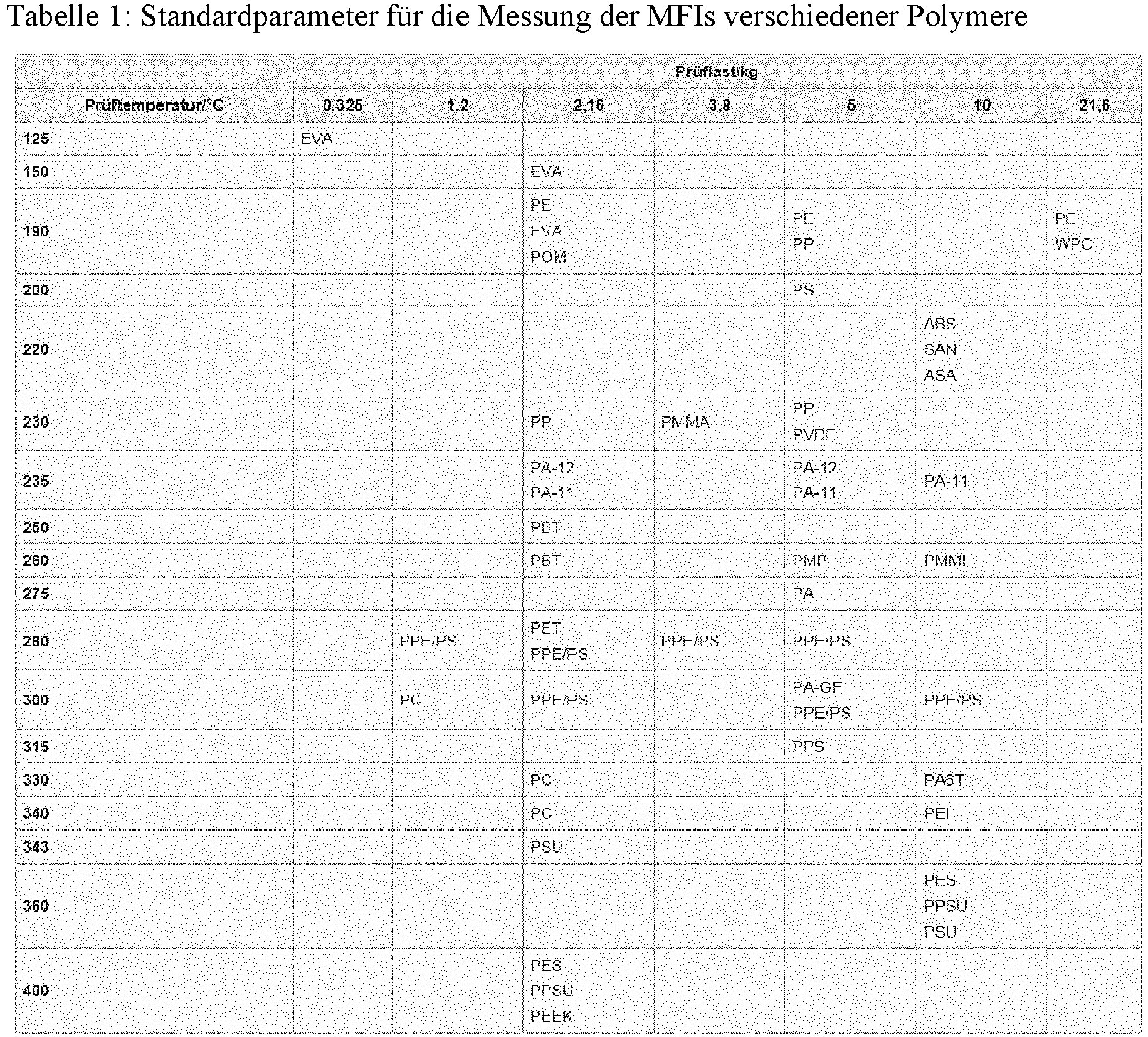
Bei der Durchführung des erfindungsgemäßen Verfahren hat es sich bewährt, (als erstes und als zweites Polymer für die Fasern des ersten und zweiten Fasertyps) generell Polymere einzusetzen, die Schmelzflussindizes (nachfolgend: MFI; melt flow index) von kleiner 1000, kleiner 500 oder kleiner 300 haben. Die Ermittlung des MFI soll, falls möglich, gemäß ISO 1133 erfolgen. Ansonsten soll nach der ASTM D1238 vorgegangen werden. In der untenstehenden Tabelle sind weitere Standardbedingungen für verschiedene Polymere aufgeführt. Sind in beiden Normen und in der angegebenen Tabelle keine Standardparameter für die Ermittlung des MFI des betreffenden Polymers vorhanden, soll auf vorhandene Tabellenwerke zurückgegriffen werden, wie z.B. das DIN Taschenbuch "Thermoplastische Formmassen", die CAMPUS-Datenbank oder die Werkstoffdatenblätter der Hersteller des betreffenden Polymers. Da oftmals für dasselbe Polymer für die Ermittlung des MFI mehrere Parametersätze, insbesondere mehrere Prüftemperaturen und/oder Prüflasten, angegeben sind, soll in einem solchen Fall immer der Parametersatz mit der höchsten Temperatur und ggf. der Parametersatz gewählt werden, der neben der höchsten Temperatur zusätzlich die höchste Prüflast vorgibt.
Als erstes Polymer kann vorteilhafterweise Polypropylen (PP), Polycarbonat (PC), Polyactd (PLA) oder Polyamid (PA) eingesetzt werden oder es können Gemische aus diesen Polymeren eingesetzt werden. Als zweites Polymer wird bevorzugt Polypropylen (PP), Polyethylen (PE), Polycarbonat (PC), Polylactd (PLA), Polyamid (PA), Polybutylenterephthalat (PBT), Polyethylenterephthalat (PET) oder Polynenylidenfuorid (PVDF) eingesetzt oder es können Gemische aus diesen Polymeren eingesetzt werden.Polypropylene (PP), polycarbonate (PC), polyacted (PLA) or polyamide (PA) can advantageously be used as the first polymer, or mixtures of these polymers can be used. Polypropylene (PP), polyethylene (PE), polycarbonate (PC), polylactd (PLA), polyamide (PA), polybutylene terephthalate (PBT), polyethylene terephthalate (PET) or polynylidene fluoride (PVDF) is preferably used as the second polymer, or mixtures of these polymers are used.
Eine besonders intensive und langanhaltende statische Aufladung kann dadurch erreicht werden, dass als erstes Polymer und/oder als zweites Polymer ein Polymer verwendet wird, das mindestens ein Additiv enthält, das Radiale binden kann, d.h. einen sogenannten Radikalfänger. Als Radikalfänger kann z.B. einen Stoff aus der Gruppe der sterisch gehinderten Amine (sogenannte HALS: Hindered-Amine Light Stabilizers), wie z.B. das unter dem Handelsnamen bekannte Chimasorb® 944, eingesetzt werden. Als Alternative zu den HALs können aber auch Stoffe aus der Gruppe der Piserazine oder aus der Gruppe der Oxazolidone eingesetzt werden.A particularly intense and long-lasting static charge can be achieved by using a polymer as the first polymer and/or as the second polymer that contains at least one additive that can bind radials, ie a so-called free-radical scavenger. A substance from the group of sterically hindered amines (so-called HALS: Hindered-Amine Light Stabilizers), such as Chimasorb® 944, known by the trade name, can be used as a free-radical scavenger. As an alternative to the HALs, substances from the piserazine group or from the oxazolidone group can also be used.
Es hat sich auch bewährt, ein erstes Polymer und/oder ein zweites Polymer zu verwenden, das mindestens ein Additiv enthält, das als inneres Gleitmittel (Migrationshilfsstoff) wirken kann, wie z.B. einen Stoff aus der Gruppe der Steramide. Als besonders geeignet hat sich Distearylethylendiamid erwiesen (sogenanntes EBS: Ethylene bis(stearamide), auch bekannt unter dem Handelsnamen Crodamide® EBS).It has also proven useful to use a first polymer and/or a second polymer that contains at least one additive that can act as an internal lubricant (migration aid), such as a substance from the group of steramides. Distearylethylenediamide (so-called EBS: ethylene bis(stearamide), also known under the trade name Crodamide® EBS) has proven to be particularly suitable.
Vorzugsweise werden Polymere eingesetzt, die mindestens eines der oben genannten Additive, das als Radikalfänger wirken kann und gleichzeitig mindestens eines der oben beschriebenen Additive, das als inneres Gleitmittel wirken kann, enthalten. Eine besonders gute Wirkung dieser Zusätze/Additive wurde in Verbindung mit Polypropylen beobachtet.Preference is given to using polymers which contain at least one of the additives mentioned above, which can act as a free-radical scavenger, and at the same time contain at least one of the additives described above, which can act as an internal lubricant. A particularly good effect of these additives was observed in connection with polypropylene.
Die als Radikalfänger wirkenden Stoffe sind in der Lage, elektrostatische Ladungen vergleichsweise langfristig zu binden. Durch die inneren Gleitmittel wird bewirkt, dass sich Stoffe, die in der Lage sind, Ladungen langfristig zu binden, in einem geschmolzenen Polymer leichter an die Oberfläche des Polymers bewegen können. Da eine elektrostatische Aufladung immer über die Oberfläche erfolgt, steht damit ein größerer Anteil dieser Stoffe für die Bindung der elektrostatischen Ladungen zur Verfügung. Die betreffenden Stoffe haben praktisch keine Wirkung, wenn sie sich im Innern des Polymers (der Polymerfaser) befinden.The substances that act as radical scavengers are able to bind electrostatic charges for a comparatively long time. The internal lubricants cause substances in a molten polymer that are capable of retaining charges over a long period of time to move more easily to the surface of the polymer. Since an electrostatic charge always takes place via the surface, a larger proportion of these substances are responsible for the binding of electrostatic charges. The substances in question have practically no effect if they are inside the polymer (the polymer fibre).
Des Weiteren kann ein erstes Polymer und/oder ein zweites Polymer eingesetzt werden, das mindestens ein weiteres Additiv enthält, das in der Lage ist, z.B. physikalisch, zusätzliche Ladungen zu binden, wie z.B. ferroelektrische Keramiken (z.B. Bariumtitanat) oder alternativ ein weiteres Additiv enthält, das dazu geeignet ist, zu verhindern, dass Ladungen, die sich bereits auf den betreffenden Fasern befinden, zu schnell abgegeben werden (d.h. das quasi einen Schutz der vorhandenen Ladungen bewirkt). Hierfür können auch vorteilhafterweise Flourchemikalien, wie z.B. fluorhaltiges Oxazolidinon, fluorhaltiges Piperazin oder ein Stearatester von Pefluoralkholen, eingesetzt werden.Furthermore, a first polymer and/or a second polymer can be used which contains at least one further additive which is able, e.g. physically, to bind additional charges, such as ferroelectric ceramics (e.g. barium titanate) or alternatively contains a further additive , which is suitable for preventing charges that are already on the fibers in question from being released too quickly (i.e. which effectively protects the existing charges). Fluorine chemicals such as fluorine-containing oxazolidinone, fluorine-containing piperazine or a stearate ester of perfluoroalcohols can also advantageously be used for this purpose.
Zur weiteren Verbesserung des Filters können den Fasern des ersten Fasertyps und/oder den Fasern des zweiten Fasertyps Feinstfasern (d.h. Fasern mit einem mittleren Faserdurchmesser von kleiner 1 µm) beigemengt werden. Alternativ oder zusätzlich können den Fasern des ersten Fasertyps und/oder den Fasern des zweiten Fasertyps auch Stapelfasern, z.B. mittels eines sogenannten Rando Webers, oder Partikel, wie z.B. Aktivkohlepartikel, z.B. mittels einer Streurinne, beigemengt werden.To further improve the filter, the fibers of the first fiber type and/or the fibers of the second fiber type can be admixed with very fine fibers (i.e. fibers with an average fiber diameter of less than 1 µm). Alternatively or additionally, the fibers of the first fiber type and/or the fibers of the second fiber type can also be admixed with staple fibers, e.g. by means of a so-called rando weaver, or particles, such as activated carbon particles, e.g. by means of a scattering channel.
Die Beimengung erfolgt im erfindungsgemäßen Verfahren vor und/oder während der Ausformung des textilen Gebildes in der Sammeleinrichtung. Die Feinstfasern werden üblicherweise nicht als fertige Fasern/Partikel sondern mittels einer separaten Spinneinrichtung, z.B. mittels einer Solution-Blow-Spinneinrichtung, welche die Feinstfasern direkt vor ihrer Beimengung erzeugt, zugegeben.In the method according to the invention, the admixture takes place before and/or during the shaping of the textile structure in the collecting device. The finest fibers are usually not added as finished fibers/particles but by means of a separate spinning device, e.g. by means of a solution-blow spinning device, which produces the finest fibers directly before they are added.
Die Erfindung wird nachfolgend anhand von Ausführungsbeispielen näher erläutert. Hierzu zeigen:
- Fig. 1
- Einen schematischen Aufbau einer Meltblow-Anlage mit einem Biax-Düsenbalken mit einreihigem Aufbau,
- Fig. 2
- Einen schematischen Aufbau einer Meltblow-Anlage mit einem Biax-Düsenbalken mit mehrreihigem Aufbau,
- Fig. 3
- Einen schematischen Aufbau einer Meltblow-Anlage mit einer Düsenanordnung, die aus einem Exxon- und einem Biax-Düsenbalken besteht,
- Fig. 4
- Einen schematischen Aufbau einer Meltblow-Anlage mit einer Düsenanordnung, die aus zwei Biax-Düsenbalken besteht,
- Fig. 5
- Einen schematischen Aufbau einer Anlage mit einem Biax-Düsenbalken und einer Solution-Blow-Spinneinrichtung,
- Fig. 6
- Einen Biax-Düsenbalken mit einer Art von konzentrischen Düsen, die gleiche Kapillardurchmesser aufweisen,
- Fig. 7
- Einen Biax-Düsenbalken mit zwei verschiedenen Arten von konzentrischen Düsen, die unterschiedliche Kapillar-und/oder Düsenrohr- und/oder Luftaustrittsöffnungsdurchmesser haben,
- Fig. 8
- Eine schematische Darstellung der Geometrie einer Meltblow-Anlage mit zwei Düsenbalken,
- Fig. 9
- Eine REM-Aufnahme sowie die zugehörigen Faserverteilungen der Oberseite eines Faservlieses mit Lagenaufbau,
- Fig. 10
- Eine REM-Aufnahme sowie die zugehörigen Faserverteilungen der Unterseite eines Faservlieses mit Lagenaufbau,
- Fig. 11
- Eine REM-Aufnahme sowie die zugehörigen Faserverteilungen der Oberseite eines Faservlieses mit teilweiser Durchmischung,
- Fig. 12
- Eine REM-Aufnahme sowie die zugehörigen Faserverteilungen der Unterseite eines Faservlieses mit teilweiser Durchmischung,
- Fig. 13
- Eine REM-Aufnahme sowie die zugehörigen Faserverteilungen der Oberseite eines Faservlieses mit vollständiger Durchmischung,
- Fig. 14
- Eine REM-Aufnahme sowie die zugehörigen Faserverteilungen der Unterseite eines Faservlieses mit vollständiger Durchmischung.
- 1
- A schematic structure of a meltblow system with a biax nozzle bar with a single-row structure,
- 2
- A schematic structure of a meltblow system with a biax nozzle bar with a multi-row structure,
- 3
- A schematic structure of a meltblow system with a nozzle arrangement consisting of an Exxon and a Biax nozzle bar,
- 4
- A schematic structure of a meltblow system with a nozzle arrangement consisting of two biax nozzle bars,
- figure 5
- A schematic structure of a system with a biax nozzle bar and a solution-blow spinning device,
- 6
- A biax nozzle bar with a type of concentric nozzles that have the same capillary diameter,
- 7
- A biax nozzle bar with two different types of concentric nozzles that have different capillary and/or nozzle tube and/or air outlet diameters,
- 8
- A schematic representation of the geometry of a meltblow system with two nozzle bars,
- 9
- An REM image and the associated fiber distributions of the upper side of a fiber fleece with a layered structure,
- 10
- An SEM image and the associated fiber distributions of the underside of a layered fiber fleece,
- 11
- A SEM image and the associated fiber distributions of the upper side of a fiber fleece with partial mixing,
- 12
- An SEM image and the associated fiber distributions of the underside of a fiber fleece with partial mixing,
- 13
- An SEM image and the associated fiber distributions of the upper side of a fiber fleece with complete mixing,
- 14
- An SEM image and the associated fiber distributions of the underside of a fiber fleece with complete mixing.
In
Wie aus den
In
In
In
Durch eine geeignete Wahl der Parameter können generell jeweils Faservliese mit einem Lagenaufbau, mit einer teilweisen Durchmischung (mit Gradientenstruktur) der beiden Fasertypen oder mit einer vollständigen (weitgehend homogenen nur geringe Gradientenstrukur) Durchmischung der beiden Fasertypen hergestellt werden. In den
Experiment: Zur Untersuchung des Einflusses sowohl des Aufbaus des Faservlieses als auch des Einflusses elektrostatisch geladener Fasern im betreffenden Faservlies auf die Filtrationseigenschaften wurde eine Versuchsreihe durchgeführt. Zuerst wurden hierbei die Additive Crodamide EBS und Chimasorb 944 im Verhältnis 1:1 aufgeschmolzen und der Polymerschmelze vorzugweise durch Co-Extrusion in ausreichender Menge zugeführt. Die Schmelze wurde anschließend gut gemischt.Experiment: A series of tests was carried out to investigate the influence of both the structure of the fiber fleece and the influence of electrostatically charged fibers in the relevant fiber fleece on the filtration properties. First, the additives Crodamide EBS and Chimasorb 944 were melted in a ratio of 1:1 and added to the polymer melt in sufficient quantities, preferably by co-extrusion. The melt was then mixed well.
Bei den Vliesen mit elektrostatisch geladenen Fasern, die jeweils ein Flächengewicht von ca. 50 g/m2 aufwiesen, wurden bei deren Herstellung die beiden von den jeweiligen Düsenbalken erzeugten Faserstrahlen von beiden Seiten mit einer ausreichenden Menge Wasser besprüht und zwar bevor die beiden Faserstahlen zusammentrafen, sodass die in den Faserstrahlen enthaltenen Fasern intensiv geladen wurden.In the case of the fleeces with electrostatically charged fibers, each of which had a basis weight of approx. 50 g/m 2 , the two fiber jets generated by the respective nozzle beams were sprayed from both sides with a sufficient amount of water before the two fiber jets met , so that the fibers contained in the fiber jets became intensely charged.
Die so erzeugten Faservliese wurden anschließend mit einem Filtertester TSI Model 8130 bei einer Durchströmgeschwindigkeit von 0,1m/s mit einer 2%igen NaCl-Lösung gemessen. Die Ergebnisse sind in den beiden nachfolgenden Tabellen aufgeführt.
Überraschenderweise wurde festgestellt, dass die Faservliese mit teilweiser Durchmischung und elektrostatisch geladenen Fasern sehr viel höhere Qualtitätsfaktoren QF zeigten, als alle anderen Faservliese.
Claims (14)
- Method for producing a pleatable textile structure having electrostatically charged fibres, preferably for use as a filter material for an electret filter, where a die arrangement is used in the method and is constructed of at least two separate die bars, where at least the first die bar has concentric orifices,and a first polymer is spun into fibres of a first fibre type by means of the first die bar, and a second polymer is spun into fibres of a second fibre type by means of the second die bar,where the fibres of the first and second fibre types are spun such that the fibres of the first fibre type have a larger mean fibre diameter than the fibres of the second fibre type,where the mean values of the diameters of the two fibre types have a distance from one another such that two maxima are clearly apparent in the overall distribution of the fibre diameters,where before and/or during the shaping of the textile structure, by means of the collecting device, the fibres of the first fibre type are mixed at least in regions with the fibres of the second fibre type,and the fibres of the first fibre type and/or the fibres of the second fibre type, at least during fibre-forming and/or during drawing, are treated with a polar liquid, the fibres being thereby charged electrostatically, where before and/or during the shaping of the textile structure the fibres of the first fibre type are mixed with the fibres of the second fibre type in such a way that, at least in a part-volume of the textile structure, the proportions of the fibres of the first fibre type and of the fibres of the second fibre type exhibit a gradient profile over the cross section of the textile structure, the gradient preferably being formed such that on the side of the nonwoven which is to be disposed on the inflow side in the filter, the proportion of the coarser fibres is higher than the proportion of the finer fibres, and on the side which is to be disposed on the outflow side, the proportion of the finer fibres is higher than the proportion of the coarser fibres.
- Method according to Claim 1, characterized in that not only the fibres of the first fibre type but also the fibres of the second fibre type are electrostatically charged by means of the polar liquid.
- Method according to one of Claims 1 and 2, characterized in that water is used as polar liquid for the electrostatic charging.
- Method according to Claim 1, characterized in that before and/or during the shaping of the textile structure, the fibres of the first fibre type are mixed with the fibres of the second fibre type in such a way that in at least 50% of the volume of the textile structure, the proportions of the fibres of the first fibre type and of the fibres of the second fibre type exhibit a gradient profile.
- Method according to any of the preceding claims, characterized in that a polymer having a melt flow index of less than 800 is used as first polymer for producing the fibres of the first fibre type.
- Method according to any of the preceding claims, characterized in that a die bar with concentric orifices is used for producing the fibres of the second fibre type, and a polymer having a melt flow index of less than 2000 is used as second polymer.
- Method according to any of Claims 1 to 5, characterized in that a die bar comprising Exxon dies is used for producing the fibres of the second fibre type, and a polymer having a melt flow index of greater than 300 is used as second polymer.
- Method according to any of the preceding claims, characterized in that polypropylene, polyethylene, polycarbonate, polylactide, polyamide, polybutylene terephthalate, polyethylene terephthalate, polyvinylidene fluoride or a mixture of these polymers is used as first polymer and/or as second polymer.
- Method according to any of the preceding claims, characterized in that a first polymer and/or a second polymer is used which comprises at least one additive which is able to bind radicals.
- Method according to any of the preceding claims, characterized in that a first polymer and/or a second polymer is used which comprises at least one additive which is able to act as internal lubricant.
- Method according to any of the preceding claims, characterized in that ultrafine fibres having a mean fibre diameter of less than 1 µm are admixed to the fibres of the first fibre type and the fibres of the second fibre type before and/or during the shaping of the textile structure by means of the collecting device.
- Pleatable textile structure consisting of fibres produced by means of a melt spinning operation, where the fibres are composed of a first fibre type consisting of a first polymer and of a second fibre type consisting of a second polymer, where the mean values of the diameters of the two fibre types are at a distance from one another such that two maxima are clearly apparent in the overall distribution of the fibre diameters, and the mean diameter of the fibres of the first fibre type is larger than the mean diameter of the second fibre type, where at least in a part-volume of the textile structure, the proportions of the fibres of the first fibre type and of the fibres of the second fibre type exhibit a gradient profile over the cross section of the textile structure, where at least some of the fibres of the first and/or second fibre types are electrostatically charged, where filters having a quality factor of greater than 0.2 are producible with the textile structure.
- Pleatable textile structure according to Claim 12, characterized in that the fibres of the second fibre type are spun such that the mean value of their fibre diameters is less than 10 µm.
- Pleatable textile structure according to any of the preceding claims, characterized in that the textile structure is a nonwoven.
Applications Claiming Priority (2)
| Application Number | Priority Date | Filing Date | Title |
|---|---|---|---|
| DE102016118966 | 2016-10-06 | ||
| PCT/DE2017/100849 WO2018065014A1 (en) | 2016-10-06 | 2017-10-06 | Method for producing a foldable textile fabric with electrostatically charged fibers, and a foldable textile fabric |
Publications (2)
| Publication Number | Publication Date |
|---|---|
| EP3523472A1 EP3523472A1 (en) | 2019-08-14 |
| EP3523472B1 true EP3523472B1 (en) | 2022-05-25 |
Family
ID=60574327
Family Applications (1)
| Application Number | Title | Priority Date | Filing Date |
|---|---|---|---|
| EP17808753.2A Not-in-force EP3523472B1 (en) | 2016-10-06 | 2017-10-06 | Method for producing a foldable textile fabric with electrostatically charged fibers, and a foldable textile fabric |
Country Status (12)
| Country | Link |
|---|---|
| US (1) | US10851476B2 (en) |
| EP (1) | EP3523472B1 (en) |
| JP (1) | JP6816268B2 (en) |
| KR (3) | KR20210158865A (en) |
| CN (2) | CN109844201B (en) |
| BR (1) | BR112019001714A2 (en) |
| CA (1) | CA3036734C (en) |
| DE (1) | DE112017005071A5 (en) |
| DK (1) | DK3523472T3 (en) |
| MX (2) | MX388932B (en) |
| RU (1) | RU2700023C1 (en) |
| WO (1) | WO2018065014A1 (en) |
Families Citing this family (6)
| Publication number | Priority date | Publication date | Assignee | Title |
|---|---|---|---|---|
| DE102018108228A1 (en) | 2018-04-06 | 2019-10-10 | Groz-Beckert Kg | Process for producing a textile structure with electrostatically charged fibers and textile structures |
| DE102019204084B4 (en) * | 2019-03-25 | 2023-06-01 | Adidas Ag | Footwear, clothing items or sports accessories comprising a nonwoven fabric |
| CN111481996B (en) * | 2020-04-26 | 2021-12-24 | 福建恒安集团有限公司 | Adsorption-enhanced filter material |
| DE102020116689A1 (en) | 2020-06-24 | 2021-12-30 | Thüringisches Institut für Textil- und Kunststoff-Forschung Rudolstadt e.V. | Melamine resin filter fleece |
| DE102022000777B4 (en) * | 2022-03-04 | 2024-09-12 | Oerlikon Textile Gmbh & Co. Kg | Method and apparatus for producing electrostatically charged fibers and electret product |
| CN116356483B (en) * | 2023-06-01 | 2023-09-12 | 称道新材料科技(上海)有限公司 | Preparation method and application of high-density monocomponent antibacterial melt-blown cloth |
Family Cites Families (20)
| Publication number | Priority date | Publication date | Assignee | Title |
|---|---|---|---|---|
| JPH0798131B2 (en) * | 1991-03-15 | 1995-10-25 | チッソ株式会社 | Cylindrical filter and manufacturing method thereof |
| JPH059611A (en) | 1991-07-08 | 1993-01-19 | Mitsui Mining & Smelting Co Ltd | Assembling method of filtration unit of metal filtration device |
| DE9414040U1 (en) * | 1994-08-30 | 1995-01-19 | Hoechst Ag, 65929 Frankfurt | Nonwovens made from electret fiber blends with improved charge stability |
| US6171684B1 (en) * | 1995-11-17 | 2001-01-09 | Donaldson Company, Inc. | Filter material construction and method |
| US6375886B1 (en) | 1999-10-08 | 2002-04-23 | 3M Innovative Properties Company | Method and apparatus for making a nonwoven fibrous electret web from free-fiber and polar liquid |
| ES2245875B1 (en) * | 2004-03-26 | 2006-11-16 | Joaquin Espuelas Peñalva | MANUFACTURING AND FILTER PROCESS OF NON-WOVEN FABRIC AND / OR FILTERING INJECTED SHEETS OR STRUCTURES OBTAINED BY SUCH PROCESS FOR FILTRATION AND ELIMINATION OF THE PNEUMOFILA LEGIONELLA. |
| US20060079145A1 (en) * | 2004-10-13 | 2006-04-13 | Hollingsworth & Vose Company | Filter media with charge stabilizing and enhancing additives |
| US20070055015A1 (en) | 2005-09-02 | 2007-03-08 | Kraton Polymers U.S. Llc | Elastomeric fibers comprising controlled distribution block copolymers |
| DE102006013170A1 (en) | 2006-03-22 | 2007-09-27 | Irema-Filter Gmbh | Foldable nonwoven material useful as air filter element in motor vehicle, comprises form stabilized thicker fiber carrier material and thinner fibers determining the filtering effect |
| US7902096B2 (en) | 2006-07-31 | 2011-03-08 | 3M Innovative Properties Company | Monocomponent monolayer meltblown web and meltblowing apparatus |
| US7754041B2 (en) | 2006-07-31 | 2010-07-13 | 3M Innovative Properties Company | Pleated filter with bimodal monolayer monocomponent media |
| US7989371B2 (en) | 2007-06-22 | 2011-08-02 | 3M Innovative Properties Company | Meltblown fiber web with staple fibers |
| CN101946033B (en) | 2007-12-28 | 2012-11-28 | 3M创新有限公司 | Composite nonwoven fibrous webs and methods of making and using the same |
| US7765698B2 (en) * | 2008-06-02 | 2010-08-03 | 3M Innovative Properties Company | Method of making electret articles based on zeta potential |
| BR112013004279B1 (en) | 2010-08-23 | 2021-01-05 | Fiberweb Holdings Limited | non-woven weave and fibers with electret properties, their manufacturing processes and their use |
| RU2492912C2 (en) * | 2011-12-20 | 2013-09-20 | Федеральное государственное унитарное предприятие "Научно-исследовательский физико-химический институт им. Л.Я. Карпова" (ФГУП "НИФХИ им. Л.Я. Карпова") | Method of making polymer filtration material and filtration material |
| JP2014176775A (en) | 2013-03-13 | 2014-09-25 | Idemitsu Kosan Co Ltd | Filter, filter laminate, and fiber product comprising the same |
| CN105765124B (en) * | 2013-11-26 | 2019-02-19 | 3M创新有限公司 | Dimensionally stable meltblown nonwoven fibrous structure and method and apparatus for making the same |
| CN106687634A (en) * | 2014-06-16 | 2017-05-17 | 格罗兹-贝克特公司 | Multi-die melt blowing system for forming co-mingled structures and method thereof |
| KR20160085151A (en) | 2015-01-07 | 2016-07-15 | 도레이케미칼 주식회사 | Apparatus and method for manufacturing electret media |
-
2017
- 2017-10-06 BR BR112019001714-3A patent/BR112019001714A2/en active Search and Examination
- 2017-10-06 WO PCT/DE2017/100849 patent/WO2018065014A1/en not_active Ceased
- 2017-10-06 CN CN201780061973.8A patent/CN109844201B/en not_active Expired - Fee Related
- 2017-10-06 RU RU2019112837A patent/RU2700023C1/en active
- 2017-10-06 KR KR1020217041962A patent/KR20210158865A/en not_active Withdrawn
- 2017-10-06 CN CN202110250423.9A patent/CN113026196A/en active Pending
- 2017-10-06 EP EP17808753.2A patent/EP3523472B1/en not_active Not-in-force
- 2017-10-06 DK DK17808753.2T patent/DK3523472T3/en active
- 2017-10-06 US US16/339,629 patent/US10851476B2/en active Active
- 2017-10-06 KR KR1020197013021A patent/KR20190057385A/en not_active Ceased
- 2017-10-06 MX MX2019003830A patent/MX388932B/en unknown
- 2017-10-06 CA CA3036734A patent/CA3036734C/en not_active Expired - Fee Related
- 2017-10-06 KR KR1020207018455A patent/KR102343972B1/en not_active Expired - Fee Related
- 2017-10-06 DE DE112017005071.5T patent/DE112017005071A5/en not_active Withdrawn
- 2017-10-06 JP JP2019518399A patent/JP6816268B2/en not_active Expired - Fee Related
-
2019
- 2019-04-02 MX MX2021015790A patent/MX2021015790A/en unknown
Also Published As
| Publication number | Publication date |
|---|---|
| CN113026196A (en) | 2021-06-25 |
| KR102343972B1 (en) | 2021-12-28 |
| WO2018065014A9 (en) | 2018-06-14 |
| CA3036734A1 (en) | 2018-04-12 |
| JP2019537503A (en) | 2019-12-26 |
| KR20210158865A (en) | 2021-12-31 |
| BR112019001714A2 (en) | 2019-05-07 |
| CN109844201A (en) | 2019-06-04 |
| JP6816268B2 (en) | 2021-01-20 |
| RU2700023C1 (en) | 2019-09-12 |
| KR20200080334A (en) | 2020-07-06 |
| US10851476B2 (en) | 2020-12-01 |
| US20190338446A1 (en) | 2019-11-07 |
| MX2021015790A (en) | 2022-01-27 |
| EP3523472A1 (en) | 2019-08-14 |
| WO2018065014A1 (en) | 2018-04-12 |
| CN109844201B (en) | 2021-03-30 |
| CA3036734C (en) | 2020-06-09 |
| MX2019003830A (en) | 2019-08-05 |
| DK3523472T3 (en) | 2022-08-29 |
| DE112017005071A5 (en) | 2019-07-11 |
| KR20190057385A (en) | 2019-05-28 |
| MX388932B (en) | 2025-03-20 |
Similar Documents
| Publication | Publication Date | Title |
|---|---|---|
| EP3523472B1 (en) | Method for producing a foldable textile fabric with electrostatically charged fibers, and a foldable textile fabric | |
| DE60304195T2 (en) | HIGH-ASHRAE FILTER MEDIUM | |
| EP3088585B1 (en) | Method and device for manufacturing a spunbonding fabric made of filaments and spun fabric | |
| EP2013384B1 (en) | Nonwoven | |
| DE69624939T2 (en) | WOVEN FILTER MEDIUM HIGH STIFFNESS | |
| DE69914346T2 (en) | HIGHLY EFFECTIVE ARTIFICIAL FILTER MATERIAL | |
| DE69620227T2 (en) | HIGHLY EFFECTIVE FLEECE FOR RESPIRATORY MASK | |
| DE69323889T2 (en) | MELT-BLOWED FLEECE | |
| EP3775346A1 (en) | Method for producing a textile fabric having electrostatically charged fibers and textile fabric | |
| DE112014005114T5 (en) | Bicomponent fibers, products formed therefrom, and methods of making same | |
| EP1733088B1 (en) | Spun-bonded non-woven made of polymer fibers and use thereof | |
| DE112016002935T5 (en) | Filter media and process for their preparation | |
| EP3771761B1 (en) | Spunbond nonwoven fabric made from endless filaments and device for producing spunbond nonwoven fabric | |
| DE19956368C2 (en) | Process for the production of meltblown nonwovens, meltblown nonwovens produced therefrom and use of the meltblown nonwovens | |
| DE69734588T2 (en) | METHOD FOR PRODUCING MELTED BLOOD POLYOLEFIN FIBERS FOR MECHANICAL FILTRATION | |
| DE69209831T2 (en) | Non-woven fabric | |
| EP1239063A1 (en) | Method for producing meltblown non-wovens, non-wovens produced thereby and use of such non-wovens | |
| EP3601657B1 (en) | Filter medium, filter element and use thereof and filter arrangement | |
| DE102020127821A1 (en) | air filter | |
| DE10252414A1 (en) | Spinneret plate with e.g. trilobal or multi-arm bores for fleece manufacture has rows of bores with differing orientation from one row to the next |
Legal Events
| Date | Code | Title | Description |
|---|---|---|---|
| STAA | Information on the status of an ep patent application or granted ep patent |
Free format text: STATUS: UNKNOWN |
|
| STAA | Information on the status of an ep patent application or granted ep patent |
Free format text: STATUS: THE INTERNATIONAL PUBLICATION HAS BEEN MADE |
|
| PUAI | Public reference made under article 153(3) epc to a published international application that has entered the european phase |
Free format text: ORIGINAL CODE: 0009012 |
|
| STAA | Information on the status of an ep patent application or granted ep patent |
Free format text: STATUS: REQUEST FOR EXAMINATION WAS MADE |
|
| 17P | Request for examination filed |
Effective date: 20190506 |
|
| AK | Designated contracting states |
Kind code of ref document: A1 Designated state(s): AL AT BE BG CH CY CZ DE DK EE ES FI FR GB GR HR HU IE IS IT LI LT LU LV MC MK MT NL NO PL PT RO RS SE SI SK SM TR |
|
| AX | Request for extension of the european patent |
Extension state: BA ME |
|
| RIN1 | Information on inventor provided before grant (corrected) |
Inventor name: STAUSS, FABIAN Inventor name: ENDRISS, FRANK Inventor name: TULKE, ANDREAS Inventor name: BERKEMANN, RALPH |
|
| DAV | Request for validation of the european patent (deleted) | ||
| DAX | Request for extension of the european patent (deleted) | ||
| STAA | Information on the status of an ep patent application or granted ep patent |
Free format text: STATUS: EXAMINATION IS IN PROGRESS |
|
| 17Q | First examination report despatched |
Effective date: 20200402 |
|
| GRAP | Despatch of communication of intention to grant a patent |
Free format text: ORIGINAL CODE: EPIDOSNIGR1 |
|
| STAA | Information on the status of an ep patent application or granted ep patent |
Free format text: STATUS: GRANT OF PATENT IS INTENDED |
|
| RIC1 | Information provided on ipc code assigned before grant |
Ipc: D01D 5/098 20060101ALI20210120BHEP Ipc: D01D 10/00 20060101ALI20210120BHEP Ipc: D01F 6/04 20060101ALN20210120BHEP Ipc: D04H 1/736 20120101ALI20210120BHEP Ipc: D01F 1/10 20060101ALI20210120BHEP Ipc: D04H 1/42 20120101AFI20210120BHEP Ipc: B01D 39/16 20060101ALI20210120BHEP |
|
| INTG | Intention to grant announced |
Effective date: 20210219 |
|
| GRAJ | Information related to disapproval of communication of intention to grant by the applicant or resumption of examination proceedings by the epo deleted |
Free format text: ORIGINAL CODE: EPIDOSDIGR1 |
|
| STAA | Information on the status of an ep patent application or granted ep patent |
Free format text: STATUS: EXAMINATION IS IN PROGRESS |
|
| INTC | Intention to grant announced (deleted) | ||
| RIC1 | Information provided on ipc code assigned before grant |
Ipc: D01F 6/04 20060101ALN20210701BHEP Ipc: D01F 1/10 20060101ALI20210701BHEP Ipc: D01D 10/00 20060101ALI20210701BHEP Ipc: D01D 5/098 20060101ALI20210701BHEP Ipc: B01D 39/16 20060101ALI20210701BHEP Ipc: D04H 1/736 20120101ALI20210701BHEP Ipc: D04H 1/42 20120101AFI20210701BHEP |
|
| GRAP | Despatch of communication of intention to grant a patent |
Free format text: ORIGINAL CODE: EPIDOSNIGR1 |
|
| STAA | Information on the status of an ep patent application or granted ep patent |
Free format text: STATUS: GRANT OF PATENT IS INTENDED |
|
| INTG | Intention to grant announced |
Effective date: 20210830 |
|
| GRAS | Grant fee paid |
Free format text: ORIGINAL CODE: EPIDOSNIGR3 |
|
| GRAA | (expected) grant |
Free format text: ORIGINAL CODE: 0009210 |
|
| STAA | Information on the status of an ep patent application or granted ep patent |
Free format text: STATUS: THE PATENT HAS BEEN GRANTED |
|
| AK | Designated contracting states |
Kind code of ref document: B1 Designated state(s): AL AT BE BG CH CY CZ DE DK EE ES FI FR GB GR HR HU IE IS IT LI LT LU LV MC MK MT NL NO PL PT RO RS SE SI SK SM TR |
|
| REG | Reference to a national code |
Ref country code: GB Ref legal event code: FG4D Free format text: NOT ENGLISH |
|
| REG | Reference to a national code |
Ref country code: CH Ref legal event code: EP |
|
| REG | Reference to a national code |
Ref country code: DE Ref legal event code: R096 Ref document number: 502017013237 Country of ref document: DE |
|
| REG | Reference to a national code |
Ref country code: AT Ref legal event code: REF Ref document number: 1494300 Country of ref document: AT Kind code of ref document: T Effective date: 20220615 |
|
| REG | Reference to a national code |
Ref country code: IE Ref legal event code: FG4D Free format text: LANGUAGE OF EP DOCUMENT: GERMAN |
|
| REG | Reference to a national code |
Ref country code: DK Ref legal event code: T3 Effective date: 20220823 |
|
| REG | Reference to a national code |
Ref country code: LT Ref legal event code: MG9D |
|
| REG | Reference to a national code |
Ref country code: NL Ref legal event code: MP Effective date: 20220525 |
|
| PG25 | Lapsed in a contracting state [announced via postgrant information from national office to epo] |
Ref country code: SE Free format text: LAPSE BECAUSE OF FAILURE TO SUBMIT A TRANSLATION OF THE DESCRIPTION OR TO PAY THE FEE WITHIN THE PRESCRIBED TIME-LIMIT Effective date: 20220525 Ref country code: PT Free format text: LAPSE BECAUSE OF FAILURE TO SUBMIT A TRANSLATION OF THE DESCRIPTION OR TO PAY THE FEE WITHIN THE PRESCRIBED TIME-LIMIT Effective date: 20220926 Ref country code: NO Free format text: LAPSE BECAUSE OF FAILURE TO SUBMIT A TRANSLATION OF THE DESCRIPTION OR TO PAY THE FEE WITHIN THE PRESCRIBED TIME-LIMIT Effective date: 20220825 Ref country code: NL Free format text: LAPSE BECAUSE OF FAILURE TO SUBMIT A TRANSLATION OF THE DESCRIPTION OR TO PAY THE FEE WITHIN THE PRESCRIBED TIME-LIMIT Effective date: 20220525 Ref country code: LT Free format text: LAPSE BECAUSE OF FAILURE TO SUBMIT A TRANSLATION OF THE DESCRIPTION OR TO PAY THE FEE WITHIN THE PRESCRIBED TIME-LIMIT Effective date: 20220525 Ref country code: HR Free format text: LAPSE BECAUSE OF FAILURE TO SUBMIT A TRANSLATION OF THE DESCRIPTION OR TO PAY THE FEE WITHIN THE PRESCRIBED TIME-LIMIT Effective date: 20220525 Ref country code: GR Free format text: LAPSE BECAUSE OF FAILURE TO SUBMIT A TRANSLATION OF THE DESCRIPTION OR TO PAY THE FEE WITHIN THE PRESCRIBED TIME-LIMIT Effective date: 20220826 Ref country code: FI Free format text: LAPSE BECAUSE OF FAILURE TO SUBMIT A TRANSLATION OF THE DESCRIPTION OR TO PAY THE FEE WITHIN THE PRESCRIBED TIME-LIMIT Effective date: 20220525 Ref country code: ES Free format text: LAPSE BECAUSE OF FAILURE TO SUBMIT A TRANSLATION OF THE DESCRIPTION OR TO PAY THE FEE WITHIN THE PRESCRIBED TIME-LIMIT Effective date: 20220525 Ref country code: BG Free format text: LAPSE BECAUSE OF FAILURE TO SUBMIT A TRANSLATION OF THE DESCRIPTION OR TO PAY THE FEE WITHIN THE PRESCRIBED TIME-LIMIT Effective date: 20220825 |
|
| PG25 | Lapsed in a contracting state [announced via postgrant information from national office to epo] |
Ref country code: RS Free format text: LAPSE BECAUSE OF FAILURE TO SUBMIT A TRANSLATION OF THE DESCRIPTION OR TO PAY THE FEE WITHIN THE PRESCRIBED TIME-LIMIT Effective date: 20220525 Ref country code: PL Free format text: LAPSE BECAUSE OF FAILURE TO SUBMIT A TRANSLATION OF THE DESCRIPTION OR TO PAY THE FEE WITHIN THE PRESCRIBED TIME-LIMIT Effective date: 20220525 Ref country code: LV Free format text: LAPSE BECAUSE OF FAILURE TO SUBMIT A TRANSLATION OF THE DESCRIPTION OR TO PAY THE FEE WITHIN THE PRESCRIBED TIME-LIMIT Effective date: 20220525 Ref country code: IS Free format text: LAPSE BECAUSE OF FAILURE TO SUBMIT A TRANSLATION OF THE DESCRIPTION OR TO PAY THE FEE WITHIN THE PRESCRIBED TIME-LIMIT Effective date: 20220925 |
|
| PG25 | Lapsed in a contracting state [announced via postgrant information from national office to epo] |
Ref country code: SM Free format text: LAPSE BECAUSE OF FAILURE TO SUBMIT A TRANSLATION OF THE DESCRIPTION OR TO PAY THE FEE WITHIN THE PRESCRIBED TIME-LIMIT Effective date: 20220525 Ref country code: SK Free format text: LAPSE BECAUSE OF FAILURE TO SUBMIT A TRANSLATION OF THE DESCRIPTION OR TO PAY THE FEE WITHIN THE PRESCRIBED TIME-LIMIT Effective date: 20220525 Ref country code: RO Free format text: LAPSE BECAUSE OF FAILURE TO SUBMIT A TRANSLATION OF THE DESCRIPTION OR TO PAY THE FEE WITHIN THE PRESCRIBED TIME-LIMIT Effective date: 20220525 Ref country code: EE Free format text: LAPSE BECAUSE OF FAILURE TO SUBMIT A TRANSLATION OF THE DESCRIPTION OR TO PAY THE FEE WITHIN THE PRESCRIBED TIME-LIMIT Effective date: 20220525 Ref country code: CZ Free format text: LAPSE BECAUSE OF FAILURE TO SUBMIT A TRANSLATION OF THE DESCRIPTION OR TO PAY THE FEE WITHIN THE PRESCRIBED TIME-LIMIT Effective date: 20220525 |
|
| REG | Reference to a national code |
Ref country code: DE Ref legal event code: R097 Ref document number: 502017013237 Country of ref document: DE |
|
| PG25 | Lapsed in a contracting state [announced via postgrant information from national office to epo] |
Ref country code: AL Free format text: LAPSE BECAUSE OF FAILURE TO SUBMIT A TRANSLATION OF THE DESCRIPTION OR TO PAY THE FEE WITHIN THE PRESCRIBED TIME-LIMIT Effective date: 20220525 |
|
| PLBE | No opposition filed within time limit |
Free format text: ORIGINAL CODE: 0009261 |
|
| STAA | Information on the status of an ep patent application or granted ep patent |
Free format text: STATUS: NO OPPOSITION FILED WITHIN TIME LIMIT |
|
| 26N | No opposition filed |
Effective date: 20230228 |
|
| REG | Reference to a national code |
Ref country code: DE Ref legal event code: R119 Ref document number: 502017013237 Country of ref document: DE |
|
| REG | Reference to a national code |
Ref country code: DK Ref legal event code: EBP Effective date: 20221031 |
|
| PG25 | Lapsed in a contracting state [announced via postgrant information from national office to epo] |
Ref country code: SI Free format text: LAPSE BECAUSE OF FAILURE TO SUBMIT A TRANSLATION OF THE DESCRIPTION OR TO PAY THE FEE WITHIN THE PRESCRIBED TIME-LIMIT Effective date: 20220525 Ref country code: MC Free format text: LAPSE BECAUSE OF FAILURE TO SUBMIT A TRANSLATION OF THE DESCRIPTION OR TO PAY THE FEE WITHIN THE PRESCRIBED TIME-LIMIT Effective date: 20220525 |
|
| REG | Reference to a national code |
Ref country code: CH Ref legal event code: PL |
|
| REG | Reference to a national code |
Ref country code: BE Ref legal event code: MM Effective date: 20221031 |
|
| GBPC | Gb: european patent ceased through non-payment of renewal fee |
Effective date: 20221006 |
|
| PG25 | Lapsed in a contracting state [announced via postgrant information from national office to epo] |
Ref country code: LU Free format text: LAPSE BECAUSE OF NON-PAYMENT OF DUE FEES Effective date: 20221006 |
|
| PG25 | Lapsed in a contracting state [announced via postgrant information from national office to epo] |
Ref country code: LI Free format text: LAPSE BECAUSE OF NON-PAYMENT OF DUE FEES Effective date: 20221031 Ref country code: FR Free format text: LAPSE BECAUSE OF NON-PAYMENT OF DUE FEES Effective date: 20221031 Ref country code: DE Free format text: LAPSE BECAUSE OF NON-PAYMENT OF DUE FEES Effective date: 20230503 Ref country code: CH Free format text: LAPSE BECAUSE OF NON-PAYMENT OF DUE FEES Effective date: 20221031 |
|
| PG25 | Lapsed in a contracting state [announced via postgrant information from national office to epo] |
Ref country code: BE Free format text: LAPSE BECAUSE OF NON-PAYMENT OF DUE FEES Effective date: 20221031 |
|
| PG25 | Lapsed in a contracting state [announced via postgrant information from national office to epo] |
Ref country code: IE Free format text: LAPSE BECAUSE OF NON-PAYMENT OF DUE FEES Effective date: 20221006 Ref country code: GB Free format text: LAPSE BECAUSE OF NON-PAYMENT OF DUE FEES Effective date: 20221006 Ref country code: DK Free format text: LAPSE BECAUSE OF NON-PAYMENT OF DUE FEES Effective date: 20221031 |
|
| REG | Reference to a national code |
Ref country code: AT Ref legal event code: MM01 Ref document number: 1494300 Country of ref document: AT Kind code of ref document: T Effective date: 20221006 |
|
| PG25 | Lapsed in a contracting state [announced via postgrant information from national office to epo] |
Ref country code: IT Free format text: LAPSE BECAUSE OF FAILURE TO SUBMIT A TRANSLATION OF THE DESCRIPTION OR TO PAY THE FEE WITHIN THE PRESCRIBED TIME-LIMIT Effective date: 20220525 Ref country code: AT Free format text: LAPSE BECAUSE OF NON-PAYMENT OF DUE FEES Effective date: 20221006 |
|
| PG25 | Lapsed in a contracting state [announced via postgrant information from national office to epo] |
Ref country code: HU Free format text: LAPSE BECAUSE OF FAILURE TO SUBMIT A TRANSLATION OF THE DESCRIPTION OR TO PAY THE FEE WITHIN THE PRESCRIBED TIME-LIMIT; INVALID AB INITIO Effective date: 20171006 |
|
| PG25 | Lapsed in a contracting state [announced via postgrant information from national office to epo] |
Ref country code: CY Free format text: LAPSE BECAUSE OF FAILURE TO SUBMIT A TRANSLATION OF THE DESCRIPTION OR TO PAY THE FEE WITHIN THE PRESCRIBED TIME-LIMIT Effective date: 20220525 |
|
| PG25 | Lapsed in a contracting state [announced via postgrant information from national office to epo] |
Ref country code: MK Free format text: LAPSE BECAUSE OF FAILURE TO SUBMIT A TRANSLATION OF THE DESCRIPTION OR TO PAY THE FEE WITHIN THE PRESCRIBED TIME-LIMIT Effective date: 20220525 |
|
| PG25 | Lapsed in a contracting state [announced via postgrant information from national office to epo] |
Ref country code: TR Free format text: LAPSE BECAUSE OF NON-PAYMENT OF DUE FEES Effective date: 20221006 Ref country code: MT Free format text: LAPSE BECAUSE OF FAILURE TO SUBMIT A TRANSLATION OF THE DESCRIPTION OR TO PAY THE FEE WITHIN THE PRESCRIBED TIME-LIMIT Effective date: 20220525 |
|
| PG25 | Lapsed in a contracting state [announced via postgrant information from national office to epo] |
Ref country code: BG Free format text: LAPSE BECAUSE OF FAILURE TO SUBMIT A TRANSLATION OF THE DESCRIPTION OR TO PAY THE FEE WITHIN THE PRESCRIBED TIME-LIMIT Effective date: 20220525 |
|
| PG25 | Lapsed in a contracting state [announced via postgrant information from national office to epo] |
Ref country code: BG Free format text: LAPSE BECAUSE OF FAILURE TO SUBMIT A TRANSLATION OF THE DESCRIPTION OR TO PAY THE FEE WITHIN THE PRESCRIBED TIME-LIMIT Effective date: 20220525 |