EP3770681A1 - Bildanzeigevorrichtung - Google Patents
Bildanzeigevorrichtung Download PDFInfo
- Publication number
- EP3770681A1 EP3770681A1 EP19770808.4A EP19770808A EP3770681A1 EP 3770681 A1 EP3770681 A1 EP 3770681A1 EP 19770808 A EP19770808 A EP 19770808A EP 3770681 A1 EP3770681 A1 EP 3770681A1
- Authority
- EP
- European Patent Office
- Prior art keywords
- light
- image display
- reflective
- optical
- display apparatus
- Prior art date
- Legal status (The legal status is an assumption and is not a legal conclusion. Google has not performed a legal analysis and makes no representation as to the accuracy of the status listed.)
- Pending
Links
Images


Classifications
-
- G—PHYSICS
- G03—PHOTOGRAPHY; CINEMATOGRAPHY; ANALOGOUS TECHNIQUES USING WAVES OTHER THAN OPTICAL WAVES; ELECTROGRAPHY; HOLOGRAPHY
- G03B—APPARATUS OR ARRANGEMENTS FOR TAKING PHOTOGRAPHS OR FOR PROJECTING OR VIEWING THEM; APPARATUS OR ARRANGEMENTS EMPLOYING ANALOGOUS TECHNIQUES USING WAVES OTHER THAN OPTICAL WAVES; ACCESSORIES THEREFOR
- G03B21/00—Projectors or projection-type viewers; Accessories therefor
- G03B21/14—Details
- G03B21/28—Reflectors in projection beam
-
- G—PHYSICS
- G02—OPTICS
- G02B—OPTICAL ELEMENTS, SYSTEMS OR APPARATUS
- G02B27/00—Optical systems or apparatus not provided for by any of the groups G02B1/00 - G02B26/00, G02B30/00
- G02B27/10—Beam splitting or combining systems
- G02B27/106—Beam splitting or combining systems for splitting or combining a plurality of identical beams or images, e.g. image replication
-
- G—PHYSICS
- G03—PHOTOGRAPHY; CINEMATOGRAPHY; ANALOGOUS TECHNIQUES USING WAVES OTHER THAN OPTICAL WAVES; ELECTROGRAPHY; HOLOGRAPHY
- G03B—APPARATUS OR ARRANGEMENTS FOR TAKING PHOTOGRAPHS OR FOR PROJECTING OR VIEWING THEM; APPARATUS OR ARRANGEMENTS EMPLOYING ANALOGOUS TECHNIQUES USING WAVES OTHER THAN OPTICAL WAVES; ACCESSORIES THEREFOR
- G03B21/00—Projectors or projection-type viewers; Accessories therefor
- G03B21/14—Details
- G03B21/20—Lamp housings
-
- G—PHYSICS
- G02—OPTICS
- G02B—OPTICAL ELEMENTS, SYSTEMS OR APPARATUS
- G02B19/00—Condensers, e.g. light collectors or similar non-imaging optics
- G02B19/0004—Condensers, e.g. light collectors or similar non-imaging optics characterised by the optical means employed
- G02B19/0028—Condensers, e.g. light collectors or similar non-imaging optics characterised by the optical means employed refractive and reflective surfaces, e.g. non-imaging catadioptric systems
-
- G—PHYSICS
- G02—OPTICS
- G02B—OPTICAL ELEMENTS, SYSTEMS OR APPARATUS
- G02B19/00—Condensers, e.g. light collectors or similar non-imaging optics
- G02B19/0033—Condensers, e.g. light collectors or similar non-imaging optics characterised by the use
- G02B19/0047—Condensers, e.g. light collectors or similar non-imaging optics characterised by the use for use with a light source
-
- G—PHYSICS
- G02—OPTICS
- G02B—OPTICAL ELEMENTS, SYSTEMS OR APPARATUS
- G02B26/00—Optical devices or arrangements for the control of light using movable or deformable optical elements
- G02B26/08—Optical devices or arrangements for the control of light using movable or deformable optical elements for controlling the direction of light
- G02B26/0816—Optical devices or arrangements for the control of light using movable or deformable optical elements for controlling the direction of light by means of one or more reflecting elements
- G02B26/0833—Optical devices or arrangements for the control of light using movable or deformable optical elements for controlling the direction of light by means of one or more reflecting elements the reflecting element being a micromechanical device, e.g. a MEMS mirror, DMD
-
- G—PHYSICS
- G02—OPTICS
- G02B—OPTICAL ELEMENTS, SYSTEMS OR APPARATUS
- G02B27/00—Optical systems or apparatus not provided for by any of the groups G02B1/00 - G02B26/00, G02B30/00
- G02B27/09—Beam shaping, e.g. changing the cross-sectional area, not otherwise provided for
- G02B27/0927—Systems for changing the beam intensity distribution, e.g. Gaussian to top-hat
-
- G—PHYSICS
- G02—OPTICS
- G02B—OPTICAL ELEMENTS, SYSTEMS OR APPARATUS
- G02B27/00—Optical systems or apparatus not provided for by any of the groups G02B1/00 - G02B26/00, G02B30/00
- G02B27/09—Beam shaping, e.g. changing the cross-sectional area, not otherwise provided for
- G02B27/0938—Using specific optical elements
- G02B27/095—Refractive optical elements
- G02B27/0955—Lenses
- G02B27/0961—Lens arrays
-
- G—PHYSICS
- G02—OPTICS
- G02B—OPTICAL ELEMENTS, SYSTEMS OR APPARATUS
- G02B27/00—Optical systems or apparatus not provided for by any of the groups G02B1/00 - G02B26/00, G02B30/00
- G02B27/30—Collimators
-
- G—PHYSICS
- G02—OPTICS
- G02B—OPTICAL ELEMENTS, SYSTEMS OR APPARATUS
- G02B3/00—Simple or compound lenses
-
- G—PHYSICS
- G02—OPTICS
- G02B—OPTICAL ELEMENTS, SYSTEMS OR APPARATUS
- G02B3/00—Simple or compound lenses
- G02B3/0006—Arrays
- G02B3/0037—Arrays characterized by the distribution or form of lenses
- G02B3/005—Arrays characterized by the distribution or form of lenses arranged along a single direction only, e.g. lenticular sheets
-
- G—PHYSICS
- G02—OPTICS
- G02B—OPTICAL ELEMENTS, SYSTEMS OR APPARATUS
- G02B3/00—Simple or compound lenses
- G02B3/0006—Arrays
- G02B3/0037—Arrays characterized by the distribution or form of lenses
- G02B3/0056—Arrays characterized by the distribution or form of lenses arranged along two different directions in a plane, e.g. honeycomb arrangement of lenses
-
- G—PHYSICS
- G02—OPTICS
- G02B—OPTICAL ELEMENTS, SYSTEMS OR APPARATUS
- G02B5/00—Optical elements other than lenses
- G02B5/08—Mirrors
-
- G—PHYSICS
- G03—PHOTOGRAPHY; CINEMATOGRAPHY; ANALOGOUS TECHNIQUES USING WAVES OTHER THAN OPTICAL WAVES; ELECTROGRAPHY; HOLOGRAPHY
- G03B—APPARATUS OR ARRANGEMENTS FOR TAKING PHOTOGRAPHS OR FOR PROJECTING OR VIEWING THEM; APPARATUS OR ARRANGEMENTS EMPLOYING ANALOGOUS TECHNIQUES USING WAVES OTHER THAN OPTICAL WAVES; ACCESSORIES THEREFOR
- G03B21/00—Projectors or projection-type viewers; Accessories therefor
- G03B21/14—Details
- G03B21/20—Lamp housings
- G03B21/2006—Lamp housings characterised by the light source
- G03B21/2033—LED or laser light sources
-
- G—PHYSICS
- G03—PHOTOGRAPHY; CINEMATOGRAPHY; ANALOGOUS TECHNIQUES USING WAVES OTHER THAN OPTICAL WAVES; ELECTROGRAPHY; HOLOGRAPHY
- G03B—APPARATUS OR ARRANGEMENTS FOR TAKING PHOTOGRAPHS OR FOR PROJECTING OR VIEWING THEM; APPARATUS OR ARRANGEMENTS EMPLOYING ANALOGOUS TECHNIQUES USING WAVES OTHER THAN OPTICAL WAVES; ACCESSORIES THEREFOR
- G03B21/00—Projectors or projection-type viewers; Accessories therefor
- G03B21/14—Details
- G03B21/20—Lamp housings
- G03B21/2066—Reflectors in illumination beam
-
- G—PHYSICS
- G03—PHOTOGRAPHY; CINEMATOGRAPHY; ANALOGOUS TECHNIQUES USING WAVES OTHER THAN OPTICAL WAVES; ELECTROGRAPHY; HOLOGRAPHY
- G03B—APPARATUS OR ARRANGEMENTS FOR TAKING PHOTOGRAPHS OR FOR PROJECTING OR VIEWING THEM; APPARATUS OR ARRANGEMENTS EMPLOYING ANALOGOUS TECHNIQUES USING WAVES OTHER THAN OPTICAL WAVES; ACCESSORIES THEREFOR
- G03B21/00—Projectors or projection-type viewers; Accessories therefor
- G03B21/14—Details
- G03B21/20—Lamp housings
- G03B21/2073—Polarisers in the lamp house
-
- G—PHYSICS
- G06—COMPUTING; CALCULATING OR COUNTING
- G06F—ELECTRIC DIGITAL DATA PROCESSING
- G06F1/00—Details not covered by groups G06F3/00 - G06F13/00 and G06F21/00
- G06F1/16—Constructional details or arrangements
- G06F1/1601—Constructional details related to the housing of computer displays, e.g. of CRT monitors, of flat displays
- G06F1/1607—Arrangements to support accessories mechanically attached to the display housing
- G06F1/1609—Arrangements to support accessories mechanically attached to the display housing to support filters or lenses
-
- H—ELECTRICITY
- H04—ELECTRIC COMMUNICATION TECHNIQUE
- H04N—PICTORIAL COMMUNICATION, e.g. TELEVISION
- H04N9/00—Details of colour television systems
- H04N9/12—Picture reproducers
- H04N9/31—Projection devices for colour picture display, e.g. using electronic spatial light modulators [ESLM]
- H04N9/3141—Constructional details thereof
- H04N9/315—Modulator illumination systems
- H04N9/3152—Modulator illumination systems for shaping the light beam
-
- G—PHYSICS
- G02—OPTICS
- G02B—OPTICAL ELEMENTS, SYSTEMS OR APPARATUS
- G02B17/00—Systems with reflecting surfaces, with or without refracting elements
- G02B17/02—Catoptric systems, e.g. image erecting and reversing system
- G02B17/04—Catoptric systems, e.g. image erecting and reversing system using prisms only
-
- G—PHYSICS
- G02—OPTICS
- G02B—OPTICAL ELEMENTS, SYSTEMS OR APPARATUS
- G02B3/00—Simple or compound lenses
- G02B3/02—Simple or compound lenses with non-spherical faces
-
- G—PHYSICS
- G02—OPTICS
- G02B—OPTICAL ELEMENTS, SYSTEMS OR APPARATUS
- G02B5/00—Optical elements other than lenses
- G02B5/04—Prisms
-
- G—PHYSICS
- G02—OPTICS
- G02B—OPTICAL ELEMENTS, SYSTEMS OR APPARATUS
- G02B5/00—Optical elements other than lenses
- G02B5/08—Mirrors
- G02B5/10—Mirrors with curved faces
-
- G—PHYSICS
- G02—OPTICS
- G02B—OPTICAL ELEMENTS, SYSTEMS OR APPARATUS
- G02B5/00—Optical elements other than lenses
- G02B5/20—Filters
- G02B5/201—Filters in the form of arrays
-
- G—PHYSICS
- G02—OPTICS
- G02B—OPTICAL ELEMENTS, SYSTEMS OR APPARATUS
- G02B5/00—Optical elements other than lenses
- G02B5/30—Polarising elements
- G02B5/3083—Birefringent or phase retarding elements
Definitions
- the present technology relates to an image display apparatus.
- Patent Document 1 discloses an illumination optical system for uniformly illuminating an illuminated surface, and a projection type display apparatus such as a liquid crystal projector using the same.
- the illumination optical system described in Patent Document 1 includes a reflecting plate including a concave mirror array, a lens array, and a condenser lens. With this configuration, it is said that it is possible to apparently omit a first fly-eye lens in an integrator optical system and to uniformly irradiate an image forming element with light emitted from a light source without collimating. It is also said that the illumination optical system can realize a compact projection type display apparatus (see Patent Document 1, specification paragraphs [0024], [0027], etc.) Citation List
- Patent Literature 1 Japanese Patent Application Laid-open No. 2001-75173
- an object of the present technology is to provide an image display apparatus capable of realizing the apparatus having a reduced size.
- an image display apparatus includes a light source section and one or more optical components.
- the one or more optical components include an optical surface for dividing the light emitted from the light source into a plurality of light beams to be converged and a reflective surface for reflecting the plurality of light beams converged by the optical surface, and emit the plurality of light beams reflected by the reflective surface from the optical surface.
- the image display apparatus includes the optical component having the optical surface and the reflective surface.
- the optical surface of the optical component divides the light from the light source into the plurality of light beams to be converged and the reflective surface reflects the light beams.
- the plurality of light beams reflected by the reflective surface is emitted from the optical surface. This makes it possible to realize the apparatus having a reduced size.
- the optical surface may be configured of a lens surface of each of a plurality of lenses arranged two-dimensionally.
- the reflective surface may reflect the light beam converged by each of the plurality of lenses toward the lens surface of each of the plurality of lenses.
- the reflective surface may be arranged so as to position a focal plane of each of the plurality of lenses in the vicinity of each surface of the plurality of lenses.
- the optical surface and the reflective surface may be arranged to face each other.
- the optical surface and the reflective surface may be integrally formed.
- the image display apparatus may further include a collimating optical system for converting the light emitted from the emitting section into collimated light and guiding the collimated light into the optical surface.
- the image display apparatus may further include an image display element and an illumination optical system.
- the illumination optical system guides the plurality of the light beams emitted from the optical component to the image display surface of the image display element.
- the illumination optical system may superimpose the plurality of the light beams emitted from the optical component on the image display surface.
- the reflective surface may have a plurality of reflective areas that reflect each of the plurality of light beams.
- the plurality of reflective areas may have an equal shape each other.
- Each of the plurality of reflective areas may have a planar shape.
- the light source section may have a plurality of light sources arranged at different positions from each other.
- each of the plurality of reflective areas may have a shape corresponding to a positional relationship of the plurality of light sources.
- Each of the plurality of reflective areas may have a planar portion in a planar shape formed in a center of the reflective area, and a tapered surface portion extending obliquely from the center of the reflective area to a peripheral edge.
- the optical components are arranged so as to have different angles from each other corresponding to the positions of the plurality of light sources and may have a plurality of reflective surfaces, each of which reflects the plurality of light beams emitted from the corresponding light source of the plurality of light sources and converged by the optical surface.
- the one or more optical components may include first and second optical components.
- the image display apparatus may further include a beam splitter that splits the light emitted from the light source section, emits the light to each of the first and second optical components, and combines the plurality of light beams emitted from each of the first and second optical components.
- the present technology makes it possible to realize the apparatus having a reduced size. It should be noted that the effects described here are not necessarily limitative and may be any of effects described in the present disclosure.
- Fig. 1 is a diagram schematically showing a configuration example of an optical system of an image display apparatus according to a first embodiment of the present technology.
- the image display apparatus 100 includes a light source 1, a concave reflecting mirror 2, condenser lenses 3 and 4, a quarter-wave plate (QWP) 5, a reflective fly-eye lens 6, a polarizing beam splitter (PBS) 7, an image display element 8, and a projection lens 9.
- QWP quarter-wave plate
- PBS polarizing beam splitter
- the reflective fly-eye lens 6, the QWP 5, the condenser lens 3, the concave reflecting mirror 2, the condenser lens 4, the PBS 7, and the image display element 8 are arranged in this order.
- the reflective fly-eye lens 6, the QWP 5, the condenser lenses 3 and 4, and the PBS 7 are arranged such that an axis passing through a center of the optical surface exhibiting optical characteristics such as the lens surface or the reflective surface (which may be referred to as optical axis of respective members) substantially coincides with a first reference axis A1.
- the concave reflecting mirror 2 is arranged such that a predetermined reflection characteristic is exhibited by using the first reference axis A1 as a reference.
- the image display element 8 is arranged such that a center of the image display surface 8a is aligned with the first reference axis A1.
- the first reference axis A1 is an optical axis of light traveling from the reflective fly-eye lens 6 to the image-display surface 8a.
- the projection lens 9 is arranged on a second reference axis A2 perpendicular to the first reference axis A1 and passing through a center of an optical surface 7a of the PBS 7.
- the projection lens 9 is arranged such that its optical axis substantially coincides with the second reference axis A2.
- the second reference axis A2 becomes an optical axis of image light emitted from the image displaying surface 8a and reflected by the optical surface 7a of the PBS 7.
- the light source 1 is a white light source, and a laser light source or an LED is used, for example. Needless to say that other light sources such as a mercury lamp and a xenon lamp may be used. In the present embodiment, the light source 1 corresponds to the light source section.
- the concave reflecting mirror 2 reflects white light emitted from the light source 1 toward the condenser lens 3.
- a wire grid polarizing film is used as the concave reflecting mirror 2. Therefore, with respect to the optical surface 2a of the concave reflecting mirror 2, light of a predetermined polarization state (here S-polarized light) is reflected, and light of the other polarization state (here P-polarized light). Therefore, the concave reflecting mirror 2 functions as a polarizing element. Needless to say that the concave reflecting mirror 2 may be formed by the polarizing element other than the wire grid polarizing film.
- the condenser lens 3 condenses and emits the white light reflected by the concave reflecting mirror 2.
- the condenser lens 3 converts the white light reflected by the concave reflecting mirror 2 into collimated light (parallel light).
- the collimated white light is then emitted along the first reference axis A1 toward the QWP 5 and the reflective fly-eye lens 6.
- the concave reflecting mirror 2 and the condenser lens 3 realizes the collimating optical system that the white light emitted from the light source 1 is converted into the collimated light and is guided to an optical surface 12 of the reflective fly-eye lens 6.
- the concave reflecting mirror 2 having the optical surface 2a in a concave shape By using the concave reflecting mirror 2 having the optical surface 2a in a concave shape, it becomes possible to suppress an optical load of the condenser lens 3, to thereby reducing the size of the condenser lens 3. It also becomes possible to shorten an optical path length of the white light. As a result, it becomes possible to realize the image display apparatus 100 having a reduced size.
- the QWP 5 provides the polarization plane of the incident light with a 90° phase differential.
- the specific configuration of the QWP 5 is not limited, and may be arbitrarily designed.
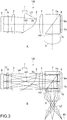
- Fig. 2 is a schematic diagram showing a configuration example of the reflective fly-eye lens 6.
- the reflective fly-eye lens 6 has the optical surface 12 and the reflective surface 13.
- the optical surface 12 is constituted by respective lens surfaces 14a of the plurality of lenses 14 arranged two-dimensionally.
- the plurality of lenses 14 has a substantially equal shape each other. Accordingly, the plurality of lens surfaces 14a also has a substantially equal shape.
- each optical axis passing through a center of each lens surface 14a extends in the same direction. Also, respective positions of tops of the lens surfaces 14a are also the same. Therefore, the focal plane of each lens 14 (plane perpendicular to optical axis including focal point) will be configured at the same position.
- the reflective surface 13 has a planar shape and is arranged so as to face the optical surface 12.
- the reflective surface 13 is arranged so as to position each focal plane F of the plurality of lenses 14 in the vicinity of each surface of the plurality of lens surfaces 14a. That is, the reflective surface 13 is arranged at a position about half distant from the focal length of the lens 14 from each lens 14.
- the reflective surface 13 is configured in common in one plane with respect to the plurality of lenses 14 and is arranged at a position with which the focal plane F of each lens 14 is roughly matched with a surface of each lens surface 14a.
- the reflective surface 13 has a plurality of reflecting areas 15 corresponding to the plurality of lenses 14. With respect to one lens 14 (lens surface 14a), one reflective area 15 is arranged.
- the plurality of reflective areas 15 has an equal shape each other and has a planar shape in the present embodiment.
- the collimated light L1 When the collimated light L1 is entered on the optical surface 12 of the reflective fly-eye lens 6, the collimated light L1 is divided into a plurality of light beams L2 and condensed by each of the plurality of lenses 14.
- the reflective surface 13 is arranged at a position approximately half the focal length of the lens 14 from each lens 14. Therefore, a plurality of light beams L2 divided is reflected toward each lens surface 14a by the reflecting area 15 of the reflective surface 13 while being condensed, and is condensed and emitted in the vicinity of each lens surface 14a.
- the reflective fly-eye lens 6 functions as an optical component that has an optical surface that divides the light emitted from the light source section into a plurality of light beams and condenses the light and a reflective surface that reflects the plurality of light beams converged by the optical surface, and emits the plurality of light beams reflected by the reflective surface from the optical surface.
- the reflective fly eye-lens 6 is formed as one component. Therefore, the optical surface 12 and the reflective surface 13 are integrally formed.
- the reflective fly-eye lens 6 can be easily formed by glass molding, injection molding using a transparent resin material, or the like. It should be appreciated that any other method may be used, such as cutting. Note that a reflective film or the like may be formed on the reflective surface 13 from outside.
- the condenser lens 4 condenses the plurality of light beams emitted from the reflective fly-eye lens 6.
- the PBS 7 is a prismatic beam splitter, which splits the incident light on the basis of the polarization state of the incident light by the optical surface 7a. In the present embodiment, it is designed to have a high reflectance in the S-polarized light with respect to the optical surface 7a and a high transmittance in the P-polarized light.
- the reflective image display element 8 is arranged facing the first plane 7b perpendicular to the first reference axis A1 of the PBS 7.
- the image display element 8 for example, a high resolution and an ultra-compact micro display are used.
- a reflective liquid crystal panel, a digital micromirror device (DMD) DLP, an organic electroluminescence (Electro-Luminescence panels), and the like can be employed. It should be appreciated that the present technology is applicable to an image display element that is not included in a micro display or other types of image display elements.
- a color filter is mounted on the image display element 8, a sub-pixel of RGB (sub-pixel) is arranged for one pixel.
- the sub-pixel of RGB modulates the white light on the basis of the image signal including the image information of each color of RGB.
- the image light including each modulated light of RGB is emitted from the image display surface 8a.
- the projection lens 9 is arranged so as to face the second surface 7c perpendicular to the second reference axes A2 of the PBS 7.
- the projection lens 9 projects the image light generated by the image display element 8 on a screen or the like.
- the specific configuration of the projection lens 9 is not limited and may be arbitrarily designed.
- Fig. 3 is a diagram for explaining an optical path on which the image is projected.
- white light L3 is emitted from the light source 1 toward the concave reflecting mirror 2.
- a polarization state of the white light L3 may be matched with the optical plane 2a of the concave reflecting mirror 2 by using a polarizing plate or the like so as to provide S-polarized light with respect to the optical plane 2a of the concave reflecting mirror 2. This makes it possible to suppress the loss of light (decrease in amount of light) and to improve brightness.
- the white light L3 is converted into collimated light and is emitted to the QWP 5.
- the QWP 5 the polarization state of the white light L3 is changed and emitted to the reflective fly-eye lens 6.
- the white light L3 (corresponding to L1 in Fig. 2 ) is divided into the plurality of light beams L2 and is condensed.
- the plurality of light beams L2 being condensed is reflected on the reflecting area 15 of the reflective surface 13 and condensed in the vicinity of the lens surface 14a. Therefore, in the vicinity of the lens surface 14a, the image of the light source 1 is imaged.
- the plurality of light beams L2 reflected by the reflecting area 15 of the reflective surface 13 is emitted from the plurality of lens surfaces 14a.
- a plurality of light beams emitted from the optical surface 12 of the reflective fly-eye lens 6 is denoted as a plurality of light beams L4.
- the plurality of light beams L4 emitted from the reflective fly-eye lens 6 is changed in the polarization state by the QWP 5. Since the white light L3 is transmitted through the QWP 5 twice, the polarization direction of the light is rotated by 90°.
- the polarization state of the plurality of light beams L4 becomes the P-polarized light with respect to the optical plane 2a of the concave reflecting mirror 2. Therefore, the plurality of light beams L4 emitted from the reflective fly eye lens 6 is condensed by the condenser lens 3 and then is transmitted through the concave reflecting mirror 2.
- the plurality of light beams L4 transmitted through the concave reflecting mirror 2 is condensed by the condenser lens 4, is transmitted through the optical surface 7a of the PBS 7, and is irradiated to the image display element 8. Therefore, the optical system is appropriately designed such that the P-polarized light with respect to the optical surface 2a of the concave reflecting mirror 2 becomes also the P-polarized light with respect to the optical surface 7a of the PBS 7, for example.
- the polarization states may be controlled by a polarizing element such as a half-wave plate so that the plurality of light beams L4 transmitted through the concave reflecting mirror 2 becomes also P-polarized light with respect to the optical surface 7a of the PBS 7.
- the plurality of light beams L4 emitted from the reflective fly eye lens 6 is irradiated so as to be superimposed on the image display surface 8a of the image display element 8. That is, in the present embodiment, the a plurality of light beams L4 is superimposed on the image display surface 8a using the image of the light source 1 as the secondary light source that is condensed by the lens 14, is reflected by the reflective area 15 of the reflective surface 13, and imaged again on near the lens surface 14a. Thus, it becomes possible to irradiate the white light having the uniformed brightness (intensity) to the image display surface 8a.
- the present embodiment realizes the illumination optical system for guiding the plurality of light beams emitted from the optical component to the image display surface of the image display element by the reflective fly-eye lens 6, the QWP 5, the condenser lenses 3 and 4, and the PBS 7.
- the plurality of light beams L4 emitted from the reflective fly eye lens 6 is superimposed on the image display surface 8a.
- the condenser lens 3 also functions as the collimating optical system as well as the illumination optical system.
- the reflective fly-eye lens 6 has both of a function of dividing the white light L3 into the plurality of light beams and a function of the illumination optical system.
- collimating optical system and the illumination optical system are not limited and may be arbitrarily designed.
- the concave reflecting mirror 2 it is also possible to omit the condenser lens 3,etc. Needless to say, in this case, there is a possibility that a design for realizing the function as the illumination optical system will be newly required.
- the image light L5 including the modulated light of the respective colors of RGB is emitted from the image display surface 8a of the image display element 8.
- the P-polarized components of the image light L5 are reflected by the optical surface 7a of the PBS 7 and are emitted from the second surface 7c along the second reference axis A2.
- the image light L5 emitted from the second surface 7c is projected on a projection object 60 such as a screen by the projection lens 9. In this way, a full-color image is displayed.
- an image display element 8 that does not mount a color filter, and a color wheel may be provided.
- each color light of RGB is generated from the white light and is irradiated to the image display surface 8a in a time division manner.
- each color light is modulated on the basis of the image signal including the image information about each color of RGB, and the image light of each color (modulated light) is generated.
- the generated image light L5 of each color is reflected by the optical surface 7a of the PBS 7 and projected by the projection lens 9. Accordingly, the image light L5 of each color of RGB will be projected in a time division manner. Even in such a configuration, it is possible to display a full-color image.
- the reflective fly-eye lens 6 having the optical surface 12 and the reflective surface 13 are mounted.
- the white light L3 from the light source 1 is divided into the plurality of light beams L4 by the optical surface 12 of the reflective fly eye lens 6, is condensed, and is reflected by the reflective surface 13.
- the plurality of light beams L4 reflected by the reflective surface 13 is emitted from the optical surface 12. This makes it possible to realize the image display apparatus 100 having a reduced size.
- light pipes also called as rods
- two fly-eye lenses may be used for the illumination system to improve the efficiency of the illumination and ensure uniformity of the illumination image. If such a configuration is employed, since the optical system becomes longer, it is difficult to reduce the size of the apparatus. In particular, if the illumination system is constituted by a conventional fly-eye optical system, it is advantageous for improvement of the illumination efficiency, but the size reduction of the apparatus is a problem.
- the reflective fly-eye lens 6 it is possible to significantly reduce the length of the optical system while exhibiting a high illumination efficiency comparable to that of the conventional fly-eye optical system. As a result, it is possible to realize the image display apparatus 100 having a reduced size, and it is very advantageous for application to eyewear, for example. Further, by using the reflective fly-eye lens 6, it also becomes possible to reduce the number of components and to reduce the cost.
- the present technology is not limited to eyewear, and can be applied to various apparatuses capable of displaying images.
- a projector a TV, a notebook PC, a tablet terminal, a smart phone, a digitizer, a PDA (Personal Digital Assistants), a portable AV player, a digital still camera, a camcorder, a gaming machine, an electronic book terminal, an ATM (Automatic Teller Machine), a station ticket vending machine, a car navigation system, or the like may be configured as an image display apparatus according to the present technology.
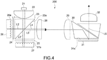
- Fig. 4 is a diagram schematically showing a configuration example of an optical system of the image display apparatus 200 according to the present embodiment.
- the image display apparatus 200 includes a light source 21, a collimating lens 22, a PBS 23, QWPs 24 and 25, a first reflective fly-eye lens 26, a second reflective fly-eye lens 27, a condenser lenses 28 and 29, a TIR prism (internal total reflection prism) 30, an image display element 31, and a projection lens 32.
- the white light L1 emitted from the light source 21 is collimated by the collimating lens 22, and then divided by the optical surface 23a of the PBS 23.
- the S-polarized component L2 of the white light L1 is reflected by the optical surface 23a and is guided to the first reflective fly-eye lens 26.
- the P polarization component L3 of the white light L1 is transmitted through the optical surface 23a and is guided to the second reflective fly-eye lens 27.
- the plurality of light beams L4 is emitted from the optical surface 26a of the first reflective fly-eye lens 26.
- the plurality of light beams L4 becomes P-polarized light because it is transmitted through the QWP 24 twice and transmits through the optical surface 23a of the PBS 23.
- the plurality of light beams L5 is emitted from the optical surface 27a of the second reflective fly-eye lens 27.
- the plurality of light beams L5 becomes S-polarized light because it is transmitted through the QWP 25 twice and is reflected by the optical surface 23a of the PBS 23.
- the plurality of light beams L4 emitted from the first reflective fly eye lens 26 and the plurality of light beams L5 emitted from the second reflective fly eye lens 27 are combined coaxially.
- the plurality of coaxially combined light beams L4 and L5 are superimposed on the image display surface 31a of the image display element 31 via the condenser lenses 28 and 29 and the TIR prism 30.
- Image light L6 is generated by the image display element 31, and is emitted from the image display surface 31a.
- the image light L6 emitted from the image display surface 31a is projected on a screen or the like via the TIR prism 30 and the projection lens 32. Note that any of a configuration including a color filter, and a configuration using the color wheel can be employed.
- the PBS 23 is arranged as the collimating optical system, and the two white lights L2 and L3 divided by the PBS 23 are guided to the two reflective fly-eye lenses (first and second reflective fly-eye lenses 26 and 27). Then, the plurality of light beams L4 and L5 are emitted by the first and second reflective fly-eye lenses 26 and 27. This makes it possible to suppress a loss of light (decrease in amount of light) and to improve the brightness.
- the TIR prism 30 As the illumination optical system, by using the TIR prism 30, it is possible to shorten the optical path length and to reduce the size of the apparatus.
- the first and second reflective fly-eye lenses 26 and 27 correspond to the first and second optical components included in one or more optical components.
- the PBS 23 functions as a beam splitter that divides the light emitted from the light source section to emit to each of the first and second optical components and combines the plurality of light beams emitted from each of the first and second optical components.
- the beam splitter according to the present technology may be realized by an optical component different from the PBS.
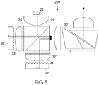
- Fig. 5 is a schematic diagram showing a modification of the image display apparatus 200 shown in Fig. 4 .
- a condenser lens 33 is arranged between a first reflective fly-eye lens 26' and a QWP 24'.
- a condenser lens 34 is also arranged between a second reflective fly eye lens 27' and a QWP25'.
- Fig. 6 is a diagram schematically showing a configuration example of an optical system of an image display apparatus 300 according to a third embodiment of the present technology.
- the image display apparatus 300 as compared with the image display apparatus 100 according to the first embodiment, configurations of a light source section 41 and a reflective fly-eye lens 43 are different. The rest of the configurations is equal to those of the image display apparatus 100, and therefore, the same reference numerals as those in Fig. 1 will be used as appropriate to explain the configuration.
- a color image is projected by a field sequential method. That is, each light of RGB is irradiated on the image display surface 8a of the image display element 8 in a time-division manner. In conformity with the timing, each color light is modulated on the basis of the image signal including the image information about each color of RGB, and the image light of each color (modulated light) is generated. The generated image light of each color is projected in time division manner by the projection lens 9.
- the light source section 41 is configured as an LED array light source including a red LED 42R, a green LED 42G, and a blue LED 42B.
- the red LED 42R, the green LED 42G, and the blue LED 42B are arranged at different positions from each other with respect to the concave reflecting mirror 2.
- the red LED 42R, the green LED 42G, and the blue LED 42B correspond to the plurality of light sources arranged at different positions from each other.
- the reflective fly-eye lens 43 has a lens body 44 and a dichroic wedge plate 46.
- the lens body 44 has a configuration substantially equal to the reflective fly-eye lens 6 shown in Fig. 1 and has an optical surface 45 having a plurality of lens surfaces.
- the dichroic wedge plate 46 is connected to a rear surface 47 of the lens body 44 opposite the optical surface 45.
- the rear surface 47 is a surface corresponding to the reflective surface 13 of the reflective fly-eye lens 6 shown in Fig. 1 , but is not used as a reflective surface in the present embodiment. Note that an antireflection film or the like may be formed on this rear surface 47.
- the dichroic wedge plate 46 has a plurality of reflective surfaces having a property of selectively reflecting color light within a predetermined wavelength range and transmitting light within other wavelength ranges.
- a reflective surface 48R for selectively reflecting red light, a reflective surface 48G for selectively reflecting green light, and a reflective surface 48B for selectively reflecting blue light are provided.
- the reflective surfaces 48R, 48G, and 48B are arranged so that the reflection angles are different from each other.
- the reflective surface 48G for reflecting green light is arranged at an angle substantially perpendicular to the first reference axis A1.
- the reflective surface 48B for reflecting the reflective surface 48R and blue light reflecting red light are arranged at an angle oblique with respect to the first reference axis A1.
- Fig. 7 is a diagram for explaining an emission direction of light of each color of RGB.
- Fig. 7 only principal light rays are illustrated for red light R, green light G, and blue light B emitted from each of the red LED 42R, the green LED 42G, and the blue LED 42B.
- the principal light rays are light that travels through a center of the beams.
- Fig. 7 the condenser lens 3 functioning as the collimating optical system is not shown, and it is explained assuming that a conversion into the collimated light is performed with the optical surface 2a of the concave reflecting mirror 2. That is, in Fig. 7 , the light reflected by the optical surface 2a of the concave reflecting mirror 2 becomes the principal light ray of each color light collimated.
- the green light G emitted from the green LED 42G is collimated by the collimating optical system and is emitted substantially perpendicular to the reflective fly-eye lens 43 along the first reference axis A1.
- the red light R emitted from the red LED 42R arranged at a different position is collimated by the collimating optical system.
- the collimated red light R is emitted obliquely with respect to the reflective fly-eye lens 43 along a direction different from the emission direction of the green light G.
- the collimated blue light B is emitted obliquely with respect to the reflective fly-eye lens 43.
- the reflective surfaces 48R, 48G, and 48B of the dichroic wedge plate 46 are arranged at angles corresponding to the emission directions of the collimated red light R, green light G, and blue light B, respectively.
- the angles of the reflective surfaces 48R, 48G, and 48B are designed such that a plurality of light beams of the red light R divided by the optical surface 45, a plurality of light beams of the green light G divided by the optical surface 45, and a plurality of light beams of the blue light B divided by the optical surface 45 are condensed along a substantially equal direction and reflected.
- the angle of each reflective surface is designed such that a plurality of light beams of each color emitted from the optical surface 45 proceeds in a substantially equal direction with reference to the first reference axis A1. This also corresponds to aligning the optical axis of each color light emitted from the optical surface 45 of the reflective fly-eye lens 43.
- the emission directions of the collimated red light R, green light G, and blue light B correspond to the positions where the red LED 42R, the green LED 42G, and the blue LED 42B are arranged. Accordingly, it can be said that the angles of the reflective surfaces 48R, 48G, and 48B are angles corresponding to the positions of the red LED 42R, the green LED 42G, and the blue LED 42B. Specific angles to be set are not limited and may be appropriately designed in accordance with the position of each light source, the direction of the optical axis to be aligned or the like.
- the reflective surfaces 48R, 48G, and 48B of the dichroic wedge plate 46 are arranged so as to have different angles from each other corresponding to the positions of the plurality of light sources, and function as a plurality of reflective surfaces, each of which reflects a plurality of light beams emitted from the corresponding light source of the plurality of light sources and converged by the optical surface (i.e., being focused).
- Figs. 8 and 9 are diagrams schematically showing a configuration example of a reflective fly-eye lens according to a fourth embodiment of the present technology.
- a reflective fly eye lens 50 according to this embodiment can be used instead of the reflective fly eye lens 43 including the dichroic wedge plate 46.
- the reflective fly-eye lens 50 has an optical surface 52 which is constituted by a lens surface 51a of each of the plurality of lenses 51.
- the reflective fly-eye lens 50 also has a reflective surface 53 arranged to face the optical surface 52.
- the reflective surface 53 has a plurality of reflecting areas 54 corresponding to the plurality of lenses 51.
- each reflecting area 54 is appropriately designed different from the planar shape. Specifically, in each reflective area 54, a planar portion 55 having a planar shape is formed in a center of the reflective area 54. The tapered surface portions 56 are formed extending obliquely from the center of the reflective area 54 toward each peripheral edge.
- Figs. 8 and 9 the principal light rays of the red light R, the green light G, and the blue light B are illustrated.
- the green light G entered substantially perpendicular to the reflective fly-eye lens 50 converges toward each plane portion 55 of each reflecting area 54. Then, the green light G is reflected by each planar portion 55 and is emitted from each optical surface 52 along the first reference axis A1.
- the red light R and the blue light B entered obliquely with respect to the reflective fly-eye lens 50 converge toward the tapered surface portions 56 and are converged after the reflection.
- the red light R and blue light B are emitted from the optical surface 52.
- the shape of the reflective area 54 is appropriately designed so that the optical axis of each color light emitted from the optical surface 52 of the reflective fly-eye lens 50 is substantially coaxial in accordance with a point at which each color light converges and a traveling direction of the light to be converged (typically, traveling direction of principal light rays).
- each reflective area 54 is not limited to that shown in Fig. 9 and the like. In order to make the optical axes of the respective color lights substantially the same, it may be appropriately designed corresponding to the emission directions of the red light R, the green light G, and the blue light B collimated by the collimating optical system. This corresponds to designing the shapes of the respective reflective areas so as to have the shapes corresponding to the positions of the red LED 42R, the green LED 42G, and the blue LED 42B.
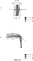
- Fig. 10 is a schematic diagram for explaining a simulation of the shape of the reflective area.
- the green light G1 is made to be entered substantially perpendicular to a center portion of a lens surface 61.
- the red light R1 and the blue light B1 are made to be entered obliquely at positions slightly offset from the center of the lens surface 61. Then, the position where the green light G1 is condensed is set near the lens surface 61 and the position where the red light R1 and the blue light B1 are respectively condensed are also set near the lens surface 61.
- the green light G2 reflected by the planar portion 62 is emitted from the lens surface 61 along substantially the same direction as the green light G1 entered.
- the red lights R2 and B2 reflected by the tapered surface portion 63 are also emitted from the lens surface 61 along substantially the same direction as the green light G2.
- Fig. 10B although the spread of the light beams is observed, it could be confirmed that the light of each color is emitted along the same direction as a whole, and the light is irradiated to substantially the same area as the white light in which three colors are combined. For example, by utilizing such a simulation, it is possible to design the shape of the reflective area with high accuracy.
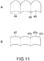
- Fig. 11 is a schematic diagram showing another configuration example of the reflective fly-eye lens.
- the planar portion 55 and the tapered surface portion 56 are formed so that a recess is formed in the center of the reflective area 54.
- the flat portion 65 and the tapered surface portion 66 may be formed so that the reflective area 64 has a convex shape as a whole.
- the tapered surface portion 66 may be configured to have an opposite slope.
- the tapered surface portion 56 may be formed so that the height is increased from the center toward the peripheral edge of the reflective area.
- the shape of the lens surface 67 may be designed for optical axis alignment of each color light.
- the shape is designed to match each color.
- any design may be utilized, e.g., designing the radius of curvature of the lens surface, making the lens surface aspherical for each color, making the lens to have a free-form surface, and others.
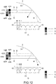
- Fig. 12 is a schematic diagram showing a modification of the image display apparatus shown in Fig. 8 .
- the LED array light source is used as the light source section.
- the LED array light source includes rows in the order of the red LED 42R, the green LED 42G, and the blue LED 42B, and rows in the order of a blue LED 42B', a green LED 42G', and a red LED 42R'. Note that, in Figs. 12A and B , two rows are shown side by side in the drawing, in practice, two rows are arranged along the vertical direction of the paper surface (depth direction).
- Fig. 12A is a diagram showing the principal light rays of RGB lights emitted from the rows in the order of the red LED 42R, the green LED 42G, and the blue LED 42B.
- Fig. 12B is a diagram showing the principal light rays of RGB lights emitted from the rows in the order of the blue LED 42B', the green LED 42G', and the red LED 42R'.
- the positions of the red LED and the blue LED are reversed in the two rows, the positions of the red light R and the blue light B emitted from the optical surface 52 of the reflective fly-eye lens 50 (positions of light beams) are also reversed.
- the configuration of the light source section in accordance with the design of the reflective fly-eye lens, it is possible to improve the quality. Note that it also becomes possible to control the width and the like of the light beam for each color.
- a polarizing element is used as an element that reflects light emitted from the light source section and transmits the plurality of light beams emitted from the reflective fly-eye lens. It is not limited to this and other optical elements such as a half mirror may be used.
- the LED light sources of RGB are mentioned as an example as the plurality of light sources arranged in different positions from each other. It is not limited to this, any light source of any color may be used as the plurality of light sources.
- the reflective fly-eye lens according to the present technology may be prepared for each color of RGB, and the respective plurality of light beams of RGB emitted from each reflective fly-eye lens may be coaxially aligned.
- center In the present disclosure, “center”, “middle”, “uniform”, “equal”, “vertical”, “collimated”, “parallel”, “planar shape”, “coplanar”, “same direction”, and the like are concepts that include “substantially center”, “substantially middle”, “substantially uniform”, “substantially equal”, “substantially vertical”, “substantially collimated”, “substantially parallel”, “substantially planar shape”, “substantially coplanar”, and “substantially same direction.” For example, it also includes states included in a predetermined range (e.g., ⁇ 10% range) with reference to "completely center”, “completely middle”, “completely uniform”, “completely equal”, “completely perpendicular”, “completely collimated”, “completely parallel”, “completely planar shape”, “completely coplanar”, “completely same direction”, or the like are also included.
- a predetermined range e.g., ⁇ 10% range
- the present technology may also have the following structures.
Applications Claiming Priority (2)
| Application Number | Priority Date | Filing Date | Title |
|---|---|---|---|
| JP2018052352 | 2018-03-20 | ||
| PCT/JP2019/007576 WO2019181404A1 (ja) | 2018-03-20 | 2019-02-27 | 画像表示装置 |
Publications (2)
| Publication Number | Publication Date |
|---|---|
| EP3770681A1 true EP3770681A1 (de) | 2021-01-27 |
| EP3770681A4 EP3770681A4 (de) | 2021-03-24 |
Family
ID=67987090
Family Applications (1)
| Application Number | Title | Priority Date | Filing Date |
|---|---|---|---|
| EP19770808.4A Pending EP3770681A4 (de) | 2018-03-20 | 2019-02-27 | Bildanzeigevorrichtung |
Country Status (6)
| Country | Link |
|---|---|
| US (1) | US11953699B2 (de) |
| EP (1) | EP3770681A4 (de) |
| JP (1) | JP7342854B2 (de) |
| KR (1) | KR20200131219A (de) |
| CN (1) | CN111837073B (de) |
| WO (1) | WO2019181404A1 (de) |
Families Citing this family (1)
| Publication number | Priority date | Publication date | Assignee | Title |
|---|---|---|---|---|
| CN113232342A (zh) * | 2021-05-07 | 2021-08-10 | 广景视睿科技(深圳)有限公司 | 一种复眼镜片模组的制作方法 |
Family Cites Families (39)
| Publication number | Priority date | Publication date | Assignee | Title |
|---|---|---|---|---|
| EP0814453A3 (de) | 1996-06-18 | 1999-07-28 | Eastman Kodak Company | Beleuchtungsvorrichtung |
| JPH11212023A (ja) | 1997-11-18 | 1999-08-06 | Seiko Epson Corp | 照明光学系および投写型表示装置 |
| JP2001075173A (ja) | 1999-09-08 | 2001-03-23 | Ricoh Co Ltd | 照明光学系及び投写型ディスプレイ装置 |
| US6739724B2 (en) * | 2001-06-22 | 2004-05-25 | Seiko Epson Corporation | Illumination optical system and projector |
| JP2005197208A (ja) | 2003-12-10 | 2005-07-21 | Seiko Epson Corp | 光源ランプ及びプロジェクタ |
| WO2007002797A2 (en) * | 2005-06-29 | 2007-01-04 | Reflexite Corporation | Method and apparatus for aperture sculpting in a microlens array film |
| JP4479686B2 (ja) | 2006-03-28 | 2010-06-09 | セイコーエプソン株式会社 | 照明装置及びプロジェクタ |
| JP4304523B2 (ja) * | 2006-05-26 | 2009-07-29 | ソニー株式会社 | 反射型液晶プロジェクタおよび画像再生装置 |
| CN101101432B (zh) * | 2006-07-06 | 2011-06-08 | 曹嘉灿 | 投影装置的光模块 |
| CN101201498A (zh) * | 2006-10-23 | 2008-06-18 | Nec液晶技术株式会社 | 显示设备、终端设备、显示面板和光学构件 |
| JP2008134617A (ja) * | 2006-10-23 | 2008-06-12 | Nec Lcd Technologies Ltd | 表示装置、端末装置、表示パネル及び光学部材 |
| CN102902146A (zh) | 2006-12-18 | 2013-01-30 | 财团法人工业技术研究院 | 高效率液晶显示投射系统 |
| DE102007048850A1 (de) | 2007-10-11 | 2009-04-16 | Robert Bosch Gmbh | Optische Anzeigeeinrichtung mit einem Mikrolinsenarray |
| CN101487928A (zh) * | 2008-01-15 | 2009-07-22 | 红蝶科技(深圳)有限公司 | 三色混合光源组件及投影系统 |
| JP4525769B2 (ja) * | 2008-02-15 | 2010-08-18 | セイコーエプソン株式会社 | スクリーン及び投射システム |
| JP2009198941A (ja) | 2008-02-25 | 2009-09-03 | Seiko Epson Corp | スクリーン及び投射システム |
| JP4539738B2 (ja) | 2008-03-05 | 2010-09-08 | セイコーエプソン株式会社 | スクリーン及び投射システム並びにスクリーンの製造方法 |
| JP2009237020A (ja) | 2008-03-26 | 2009-10-15 | Seiko Epson Corp | 光源装置及びプロジェクタ |
| CN101639195A (zh) * | 2008-07-29 | 2010-02-03 | 红蝶科技(深圳)有限公司 | 发光二极管光源装置及使用该光源装置的液晶投影设备 |
| CN102033407A (zh) | 2009-09-26 | 2011-04-27 | 陈波 | 一种对比度增强正向投影屏 |
| JP5745776B2 (ja) * | 2010-03-15 | 2015-07-08 | デクセリアルズ株式会社 | 光学積層体および建具 |
| JP2011237637A (ja) * | 2010-05-11 | 2011-11-24 | Fujifilm Corp | 反射型液晶プロジェクタ |
| JP2012003026A (ja) * | 2010-06-16 | 2012-01-05 | Sony Corp | 光学体、窓材、建具および日射遮蔽装置 |
| KR20130108359A (ko) | 2010-09-22 | 2013-10-02 | 쓰리엠 이노베이티브 프로퍼티즈 컴파니 | 경사형 이색성 색상 조합기 iii |
| JP2012230352A (ja) | 2011-04-13 | 2012-11-22 | Canon Inc | 照明光学系およびそれを用いた画像投射装置 |
| CN202453633U (zh) * | 2012-02-03 | 2012-09-26 | 上海广擎光电科技有限公司 | 一种双芯片的被动偏振式三维投影系统 |
| CN102540679B (zh) | 2012-02-22 | 2014-10-29 | 海信集团有限公司 | 光源装置、光源产生方法及包含光源装置的激光投影机 |
| JP6098064B2 (ja) * | 2012-08-08 | 2017-03-22 | ソニー株式会社 | 表示装置および照明装置 |
| CN103625154B (zh) * | 2012-08-21 | 2016-05-18 | 中钞特种防伪科技有限公司 | 一种光学防伪元件及使用该光学防伪元件的产品 |
| US8905548B2 (en) * | 2012-08-23 | 2014-12-09 | Omnivision Technologies, Inc. | Device and method for reducing speckle in projected images |
| JP5966843B2 (ja) * | 2012-10-18 | 2016-08-10 | ソニー株式会社 | 光源装置及び画像表示装置 |
| WO2014093085A1 (en) * | 2012-12-10 | 2014-06-19 | 3M Innovative Properties Company | Reflective fly eye array illuminator |
| CN105940509A (zh) | 2014-02-28 | 2016-09-14 | 松下知识产权经营株式会社 | 发光装置 |
| JP2015227998A (ja) | 2014-06-02 | 2015-12-17 | キヤノン株式会社 | 照明光学系およびこれを用いた画像表示装置 |
| DE102014118380A1 (de) * | 2014-12-11 | 2016-06-16 | Valeo Schalter Und Sensoren Gmbh | Anzeigevorrichtung für ein Kraftfahrzeug mit Kraftsensor, Kraftfahrzeug sowie Verfahren |
| JP6575361B2 (ja) | 2016-01-07 | 2019-09-18 | セイコーエプソン株式会社 | 波長変換素子、照明装置及びプロジェクター |
| CN106444255A (zh) | 2016-12-27 | 2017-02-22 | 海信集团有限公司 | 激光投影设备及其激光光源 |
| CN107797296A (zh) | 2017-11-14 | 2018-03-13 | 海信集团有限公司 | 一种缩束装置、激光光源及激光投影设备 |
| CN113031294B (zh) * | 2019-12-09 | 2022-11-11 | 觉芯电子(无锡)有限公司 | 一种散斑抑制方法、装置及激光微投影模组 |
-
2019
- 2019-02-27 EP EP19770808.4A patent/EP3770681A4/de active Pending
- 2019-02-27 KR KR1020207023164A patent/KR20200131219A/ko not_active Application Discontinuation
- 2019-02-27 CN CN201980018629.XA patent/CN111837073B/zh active Active
- 2019-02-27 WO PCT/JP2019/007576 patent/WO2019181404A1/ja unknown
- 2019-02-27 US US16/979,249 patent/US11953699B2/en active Active
- 2019-02-27 JP JP2020507474A patent/JP7342854B2/ja active Active
Also Published As
| Publication number | Publication date |
|---|---|
| CN111837073B (zh) | 2022-10-11 |
| EP3770681A4 (de) | 2021-03-24 |
| JPWO2019181404A1 (ja) | 2021-04-01 |
| CN111837073A (zh) | 2020-10-27 |
| US11953699B2 (en) | 2024-04-09 |
| WO2019181404A1 (ja) | 2019-09-26 |
| US20200400964A1 (en) | 2020-12-24 |
| KR20200131219A (ko) | 2020-11-23 |
| JP7342854B2 (ja) | 2023-09-12 |
Similar Documents
| Publication | Publication Date | Title |
|---|---|---|
| US20080055550A1 (en) | Microprojector | |
| CN106019789A (zh) | 一种彩色投影显示的光学引擎 | |
| CN107092156A (zh) | 一种彩色投影显示光学引擎 | |
| CN211403092U (zh) | 照明系统及投影装置 | |
| CN101454718B (zh) | 照明装置及使用该装置的投影型映像显示装置 | |
| US7359122B2 (en) | Prism assembly | |
| CN113391506B (zh) | 照明系统及投影装置 | |
| US20040212893A1 (en) | Polarization converting device, illumination optical system and projector | |
| US11953699B2 (en) | Image display apparatus | |
| JP2007025652A (ja) | 画像表示装置 | |
| JP2007264339A (ja) | 変調装置及びプロジェクタ | |
| JPWO2005114319A1 (ja) | プロジェクタ | |
| US7404643B2 (en) | Projector having polarization conversion element | |
| US6816206B2 (en) | Polarizing illumination optical system and projection-type display device which uses same | |
| US9964838B2 (en) | Projection display device | |
| US20040207769A1 (en) | Projection display device | |
| CN101976011A (zh) | Md短焦距投影显示装置 | |
| JP2007121693A (ja) | プロジェクタ | |
| KR100424767B1 (ko) | 투사형 영상기기 | |
| KR20050070863A (ko) | 프로젝션 시스템의 조명 광학계 | |
| JP2001356302A (ja) | 照明光学系及びこれを備えるプロジェクタ | |
| JP5104338B2 (ja) | プロジェクタ | |
| KR100826356B1 (ko) | 프로젝터 | |
| JP2004226813A (ja) | 照明装置及びこれを備えたプロジェクタ | |
| JP2009288387A (ja) | 投射型表示装置 |
Legal Events
| Date | Code | Title | Description |
|---|---|---|---|
| STAA | Information on the status of an ep patent application or granted ep patent |
Free format text: STATUS: THE INTERNATIONAL PUBLICATION HAS BEEN MADE |
|
| PUAI | Public reference made under article 153(3) epc to a published international application that has entered the european phase |
Free format text: ORIGINAL CODE: 0009012 |
|
| STAA | Information on the status of an ep patent application or granted ep patent |
Free format text: STATUS: REQUEST FOR EXAMINATION WAS MADE |
|
| 17P | Request for examination filed |
Effective date: 20200903 |
|
| AK | Designated contracting states |
Kind code of ref document: A1 Designated state(s): AL AT BE BG CH CY CZ DE DK EE ES FI FR GB GR HR HU IE IS IT LI LT LU LV MC MK MT NL NO PL PT RO RS SE SI SK SM TR |
|
| AX | Request for extension of the european patent |
Extension state: BA ME |
|
| A4 | Supplementary search report drawn up and despatched |
Effective date: 20210223 |
|
| RIC1 | Information provided on ipc code assigned before grant |
Ipc: G02B 3/00 20060101ALI20210217BHEP Ipc: G03B 21/20 20060101ALI20210217BHEP Ipc: G03B 21/14 20060101AFI20210217BHEP Ipc: G02B 5/04 20060101ALI20210217BHEP Ipc: G02B 5/08 20060101ALI20210217BHEP |
|
| DAV | Request for validation of the european patent (deleted) | ||
| DAX | Request for extension of the european patent (deleted) | ||
| RAP3 | Party data changed (applicant data changed or rights of an application transferred) |
Owner name: SONY GROUP CORPORATION |
|
| STAA | Information on the status of an ep patent application or granted ep patent |
Free format text: STATUS: EXAMINATION IS IN PROGRESS |
|
| 17Q | First examination report despatched |
Effective date: 20230202 |