EP3770101B1 - Arm mit zwei oder mehr haken - Google Patents
Arm mit zwei oder mehr haken Download PDFInfo
- Publication number
- EP3770101B1 EP3770101B1 EP20186295.0A EP20186295A EP3770101B1 EP 3770101 B1 EP3770101 B1 EP 3770101B1 EP 20186295 A EP20186295 A EP 20186295A EP 3770101 B1 EP3770101 B1 EP 3770101B1
- Authority
- EP
- European Patent Office
- Prior art keywords
- arm
- load
- designed
- hooks
- module
- Prior art date
- Legal status (The legal status is an assumption and is not a legal conclusion. Google has not performed a legal analysis and makes no representation as to the accuracy of the status listed.)
- Active
Links
Images


Classifications
-
- B—PERFORMING OPERATIONS; TRANSPORTING
- B66—HOISTING; LIFTING; HAULING
- B66C—CRANES; LOAD-ENGAGING ELEMENTS OR DEVICES FOR CRANES, CAPSTANS, WINCHES, OR TACKLES
- B66C1/00—Load-engaging elements or devices attached to lifting or lowering gear of cranes or adapted for connection therewith for transmitting lifting forces to articles or groups of articles
- B66C1/10—Load-engaging elements or devices attached to lifting or lowering gear of cranes or adapted for connection therewith for transmitting lifting forces to articles or groups of articles by mechanical means
- B66C1/105—Lifting beam permitting to depose a load through an opening
-
- B—PERFORMING OPERATIONS; TRANSPORTING
- B66—HOISTING; LIFTING; HAULING
- B66C—CRANES; LOAD-ENGAGING ELEMENTS OR DEVICES FOR CRANES, CAPSTANS, WINCHES, OR TACKLES
- B66C1/00—Load-engaging elements or devices attached to lifting or lowering gear of cranes or adapted for connection therewith for transmitting lifting forces to articles or groups of articles
- B66C1/10—Load-engaging elements or devices attached to lifting or lowering gear of cranes or adapted for connection therewith for transmitting lifting forces to articles or groups of articles by mechanical means
- B66C1/22—Rigid members, e.g. L-shaped members, with parts engaging the under surface of the loads; Crane hooks
- B66C1/34—Crane hooks
- B66C1/36—Crane hooks with means, e.g. spring-biased detents, for preventing inadvertent disengagement of loads
-
- B—PERFORMING OPERATIONS; TRANSPORTING
- B66—HOISTING; LIFTING; HAULING
- B66C—CRANES; LOAD-ENGAGING ELEMENTS OR DEVICES FOR CRANES, CAPSTANS, WINCHES, OR TACKLES
- B66C1/00—Load-engaging elements or devices attached to lifting or lowering gear of cranes or adapted for connection therewith for transmitting lifting forces to articles or groups of articles
- B66C1/10—Load-engaging elements or devices attached to lifting or lowering gear of cranes or adapted for connection therewith for transmitting lifting forces to articles or groups of articles by mechanical means
- B66C1/22—Rigid members, e.g. L-shaped members, with parts engaging the under surface of the loads; Crane hooks
- B66C1/34—Crane hooks
- B66C1/40—Crane hooks formed or fitted with load measuring or indicating devices
-
- B—PERFORMING OPERATIONS; TRANSPORTING
- B66—HOISTING; LIFTING; HAULING
- B66C—CRANES; LOAD-ENGAGING ELEMENTS OR DEVICES FOR CRANES, CAPSTANS, WINCHES, OR TACKLES
- B66C13/00—Other constructional features or details
- B66C13/16—Applications of indicating, registering, or weighing devices
-
- B—PERFORMING OPERATIONS; TRANSPORTING
- B66—HOISTING; LIFTING; HAULING
- B66C—CRANES; LOAD-ENGAGING ELEMENTS OR DEVICES FOR CRANES, CAPSTANS, WINCHES, OR TACKLES
- B66C13/00—Other constructional features or details
- B66C13/18—Control systems or devices
-
- B—PERFORMING OPERATIONS; TRANSPORTING
- B66—HOISTING; LIFTING; HAULING
- B66C—CRANES; LOAD-ENGAGING ELEMENTS OR DEVICES FOR CRANES, CAPSTANS, WINCHES, OR TACKLES
- B66C15/00—Safety gear
- B66C15/06—Arrangements or use of warning devices
- B66C15/065—Arrangements or use of warning devices electrical
-
- B—PERFORMING OPERATIONS; TRANSPORTING
- B66—HOISTING; LIFTING; HAULING
- B66C—CRANES; LOAD-ENGAGING ELEMENTS OR DEVICES FOR CRANES, CAPSTANS, WINCHES, OR TACKLES
- B66C23/00—Cranes comprising essentially a beam, boom, or triangular structure acting as a cantilever and mounted for translatory of swinging movements in vertical or horizontal planes or a combination of such movements, e.g. jib-cranes, derricks, tower cranes
- B66C23/88—Safety gear
-
- B—PERFORMING OPERATIONS; TRANSPORTING
- B66—HOISTING; LIFTING; HAULING
- B66F—HOISTING, LIFTING, HAULING OR PUSHING, NOT OTHERWISE PROVIDED FOR, e.g. DEVICES WHICH APPLY A LIFTING OR PUSHING FORCE DIRECTLY TO THE SURFACE OF A LOAD
- B66F9/00—Devices for lifting or lowering bulky or heavy goods for loading or unloading purposes
- B66F9/06—Devices for lifting or lowering bulky or heavy goods for loading or unloading purposes movable, with their loads, on wheels or the like, e.g. fork-lift trucks
- B66F9/065—Devices for lifting or lowering bulky or heavy goods for loading or unloading purposes movable, with their loads, on wheels or the like, e.g. fork-lift trucks non-masted
-
- B—PERFORMING OPERATIONS; TRANSPORTING
- B66—HOISTING; LIFTING; HAULING
- B66C—CRANES; LOAD-ENGAGING ELEMENTS OR DEVICES FOR CRANES, CAPSTANS, WINCHES, OR TACKLES
- B66C2700/00—Cranes
- B66C2700/08—Electrical assemblies or electrical control devices for cranes, winches, capstans or electrical hoists
- B66C2700/084—Protection measures
Definitions
- This invention relates to an arm with two or more hooks, designed to be used as equipment on telehandlers or other self-propelled operating machines.
- Each hook is designed to support a respective load, with a different weight from that of the other hooks, for example 25 tonnes instead of 13 tonnes or 18 tonnes and so on.
- CN 206 553 065 U discloses an arm according to the preamble of claim 1. It also discloses a method of using said arm.
- the technical purpose which forms the basis of the invention is therefore to propose an arm with two or more hooks and a method for using an arm with two or more hooks which is able to overcome the limitations of the prior art. This purpose is achieved by using the arm made according to claim 1 and by the method actuated according to claim 17.
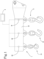
- the numeral 1 denotes an arm with two or more hooks made according to the invention.
- the beam 10 is equipped, distributed along its length and at its lower side, with several hooks 11, 12, 13, each set up to support a respective load, that is to say, a respective maximum weight value of the load.
- a relative load sensor is connected to at least one of the hooks 11, 12, 13, but preferably to all the hooks 11, 12, 13.
- each hook 11, 12, 13 may be connected to a respective load sensor 31, 32, 33 which measures the weight of the load which is supported by the hook 11, 12, 13 and consequently produces a load signal representing the measurements taken.
- the sensors 31, 32, 33 are preferably included in the beam 10 or are positioned between beam 10 and hooks 11, 12, 13.
- the arm with two or more hooks 1 is able to measure the weight which actually bears on each of the hooks 11, 12, 13 and this allows it to overcome all the limitations of the prior art, as will be clearly explained in the description of the operation of the invention.
- the invention is also configured as a fastening system for telehandlers or other self-propelled operating machines, which, as well as comprising the arm with two or more hooks 1 proposed, also includes an electronic processing unit 4 connected to the load sensors and designed to receive and process the above-mentioned load signals.
- the electronic processing unit 4 will be presented as being subdivided into separate functional modules solely for the purpose of describing the functions clearly and completely.
- processing unit 4 may be constituted by a single electronic device, if necessary also of the type commonly present on this type of machine, suitably programmed to perform the functions described; the various modules can correspond to hardware units and/or software routines forming part of the programmed device.
- the functions can be performed by a plurality of electronic devices on which the above-mentioned functional modules can be distributed.
- the processing unit 4 may have one or more microprocessors or microcontrollers for execution of the instructions contained in the memory modules and the above-mentioned functional modules may also be distributed on a plurality of local or remote calculators based on the architecture of the network in which they reside.
- the invention makes it possible to intervene manually or automatically to avoid the risks illustrated during the discussion of the prior art.
- the telehandler 2 for which the invention is intended to be used includes a frame or carriage 22 carried by driving wheels 23 which directly mounts the driver's cab 24 or mounts a tower or rotary frame on which the cab is located.
- the telehandler 2 includes an electro-hydraulic distributor 25 which controls the various hydraulic actuators 26, 27 of the invention (see the schematic representation of Figure 3 ).
- the above-mentioned operating arm 20 is telescopic and is hinged to the carriage 22 or to the tower at its proximal end, whilst at its distal end it is equipped with the coupling device 21, which has already been mentioned above, which allows the removable coupling of the equipment, including the arm 1 according to the invention.
- a second elongation / retraction actuator 27 connected to the segments, which preferably consists of a hydraulic cylinder.
- the invention may include a communication device 5 connected to the processing unit 4 and designed to provide to the operator with information relative to the loads supported by the arm 1.
- the cab 24 of the telehandler 2 or on a mobile device available to the operator, such as a remote control there may be an interface or other means designed to communicate information which allow the operator to know the actual weight which bears on a specific hook of the arm 1.
- a display unit 5 where numerical or graphical indexes allow the operator to understand which hooks 11, 12, 13 are engaged and with what weight, as well as other information such as the maximum load which can be supported by each hook or other information; moreover, it is also possible that this communication device 5 is able to produce other visual or audio signals to make known to the operator the operating condition of the arm 1.
- the processing unit 4 then comprises an information module 41 which is configured for producing information signals which are a function of the measurements of the above-mentioned sensors 31, 32, 33.
- These signals are designed to control the communication device 5, for example the above-mentioned display, in such a way that they show the operator the load data measured using the sensors 31, 32, 33.
- This first type of operation of the system according to the invention may allow the operator to immediately understand if an error has been made in estimating the load which must be attached to a certain hook 11, 12, 13 or if hook for a load of a certain weight has been incorrectly identified or if a load has been suspended on two different hooks and the weight bears more on the weaker one.
- the processing unit 4 can comprise a threshold module 42 configured for checking, for one or more hooks 11, 12, 13, whether the load carried by them exceeds or not a respective risk threshold as a function of the maximum weight value which they are designed to support.
- the threshold may be equal to the maximum weight value which can be supported less a deviation which may be fixed for all the hooks 11, 12, 13 or variable, for example a percentage of the maximum weight or other relation; there could also be a threshold equal to the maximum weight or the upper limit.
- the threshold values and any deviations may be recorded in a memory module 43 of the processing unit 4 which may also include other data, parameters and information used by the modules of the processing unit 4.
- the above-mentioned information module 41 may be connected to the threshold module 42 and be therefore configured to produce information signals designed to cause the display 5 (or other information device) to produce alarm messages directed to the operator, if the weight carried by one or more hooks 11, 12, 13 has reached or exceeded the respective risk threshold.
- the telehandler 2 is equipped with an apparatus for controlling the operating arm 2 which includes the hydraulic actuators 26, 27 mounted on the arm and the above-mentioned distributor 25; the invention uses these components for automatically controlling the dangerous conditions connected to the loads suspended from the hooks 11, 12, 13 of the arm 1.
- the processing unit 4 includes a control module 44 which is connected to the threshold module 42 and is configured for producing a control signal designed to adjust the operation of the distributor 25, as a function of the checks performed by the threshold module 42.
- the processing unit 4 may transmit to the distributor 25 a signal which causes the locking of the movements of the arm 20, or it may also produce a control signal designed to make the arm 20 perform only retraction and/or lowering movements.
- the system After the operator has connected one or more loads to the hooks 11, 12, 13 of the arm 1, the operator climbs into the cab 24 to manoeuvre the lifting arm 20 which mounts the arm 1 of the invention using suitable commands. If a load has been connected with an excessive weight to a hook 11, 12, 13, or if the load had has been incorrectly estimated, or an incorrect hook 11, 12, 13 has been used, the system according to the invention signals, for example by means of the display unit 5 and/or a loudspeaker, the potential danger in lifting the load and carrying it to the destination point.
- the system prevents the operator from moving the arm 20 by means of the commands in the cab 24.
- the invention is also configured as a method for the safe use of an arm with two or more hooks mounted on or to be mounted on an operating arm 20 of a telehandler 2; in detail, the method may be actuated by means of the arm with two or more hooks 1 described above.
- the method comprises the steps of hanging one or more loads from one or more hooks 11, 12, 13 of said arm 1; and measuring the weight of the suspended load or loads.
- the method includes steps which correspond to all or some of the functions offered by the arm 1 and by the system according to the invention, as described above.
- the method proposed may provide an operator with information representative of the weight of the loads.
- step of checking for one or more hooks 11, 12, 13, whether the weight of the load carried by them exceeds or not a respective risk threshold as a function of the maximum weight value which they are designed to support.
- the operating arm 20 may be made to perform retraction and/or lowering movements, when the load carried by one or more hooks 11, 12, 13 has reached or exceeded the respective risk threshold.
- the invention also comprises a further embodiment which allows additional advantages to be obtained.
- this embodiment makes it possible to automatically vary the load diagram applied by the processing unit to the movements of the operating arm, as a function of the various operating conditions of the arm.
- the processing unit 4 firstly includes a plurality of load diagrams recorded in the memory module.
- control module is configured for limiting the operational possibilities of the control apparatus 25, 26, 27, on the basis of a load diagram and the processing unit 4 also comprises a selection module 45 configured for automatically selecting from the memory module 43 a load diagram on the basis of signals acquired by suitable sensors.
- the processing unit 4 can consider one or more of the following parameters relative to the specific operating condition: weight measured by the load sensors, which hook or hooks the load is suspended from, the position of the arm, if it is of the variable configuration type and where the barycentre of the suspended load is located.
- the processing unit 4 comprises an identification module, configured to determine which hook(s) is/are stressed by 46 respective loads as a function of the signals produced by the respective load sensors 31, 32, 33; in this case, the selection module 45 is designed to select a relative load diagram from the memory module 43 on the basis of which hook(s) 11, 12, 13 is/are stressed.
- the processing unit 4 can comprise a weight module 47 configured for calculating the weight values supported by the hooks as a function of the signals acquired from the load sensors 31, 32, 33; in this case, the selection module 45 is designed to select a load diagram from the memory module 43, based on the weight values measured.
- the processing unit can include a barycentre module 48 configured to calculate a position of the barycentre of a load hanging from the hooks as a function of which the hook(s) are stressed by respective loads and weight values supported by the hooks; in this case, the selection module 45 is designed to select a load diagram from the memory module 43, based on said position of the barycentre.
- a barycentre module 48 configured to calculate a position of the barycentre of a load hanging from the hooks as a function of which the hook(s) are stressed by respective loads and weight values supported by the hooks; in this case, the selection module 45 is designed to select a load diagram from the memory module 43, based on said position of the barycentre.
- the position of the barycentre may be calculated as a function of any reference, preferably integral with the machine.
- the system according to the invention includes at least one position sensor (not illustrated) designed to detect the current configuration of the arm 1 and to transmit a position signal to the processing unit 4.
- the processing unit 4 includes a position module 49 designed for detecting the configuration of the arm 1 as a function of the position signal and the selection module 45 is designed to select a load diagram from the memory module 43, on the basis of the configuration of the arm 1 detected.
- the invention overcomes the limitations of the prior art where the choice of the suitable diagram is still left to the operator, depending on the hook which the operator wants to load or the configuration in which the operator wants to use the accessory 1.
- the invention avoids not only the risks of error in the selection of the load diagram to be applied, but also prevents the operator from using a diagram which is too permissive with respect to the specific operating conditions of the arm.
- the invention prevents the operator from being forced to select a diagram which is or is not safe in order to protect from overloading or from being excessively conservative and causing loss of performance in terms of arm extension and manoeuvring.
- the processing unit 4 makes it possible to immediately know the weight of the loads on each hook 11, 12, 13 and the relative positions and is therefore able to calculate the value of the total load and the actual position of its barycentre, with the result of being able to automatically select the load diagram most suitable for maximising safety and performance.
Landscapes
- Engineering & Computer Science (AREA)
- Mechanical Engineering (AREA)
- Structural Engineering (AREA)
- Transportation (AREA)
- Life Sciences & Earth Sciences (AREA)
- Civil Engineering (AREA)
- Geology (AREA)
- Automation & Control Theory (AREA)
- Manipulator (AREA)
- Forklifts And Lifting Vehicles (AREA)
- Load-Engaging Elements For Cranes (AREA)
- Sewing Machines And Sewing (AREA)
- Automatic Analysis And Handling Materials Therefor (AREA)
Claims (23)
- Arm (1) mit zwei oder mehr Haken, umfassend einen Trägerbalken (10), der dafür vorgesehen ist, mit einem Arbeitsarm (20) eines Teleskopladers (2) oder einer anderen selbstfahrenden Arbeitsmaschine verbunden zu werden, und außerdem umfassend eine Vielzahl von Haken (11, 12, 13), die entlang des Balkens (10) verteilt sind und die jeweils dafür ausgelegt sind, eine entsprechende Last zu tragen, wobei einer oder mehrere der Haken (11, 12, 13) mit einem Lastsensor (31, 32, 33) verbunden ist/sind; wobei der Arm (1) dadurch gekennzeichnet ist, dass der Trägerbalken (10) dafür ausgelegt ist, mit einer Kupplungsvorrichtung (21) verbunden zu werden, mit der ein distales Ende des Arbeitsarms (20) eines Teleskopladers (2) ausgestattet ist.
- Arm (1) nach dem vorhergehenden Anspruch, wobei jeder Haken (11, 12, 13) mit einem entsprechenden Lastsensor (31, 32, 33) verbunden ist.
- Kupplungssystem für eine selbstfahrende Arbeitsmaschine, umfassend den Arm (1) nach einem beliebigen der vorhergehenden Ansprüche und eine elektronische Verarbeitungseinheit (4), die mit den Lastsensoren (31, 32, 33) verbunden ist, wobei die zuletzt genannten dafür vorgesehen sind, jeweils ein Lastsignal als Funktion des Gewichts der von dem entsprechenden Haken (11, 12, 13) getragenen Last zu erzeugen.
- System nach dem vorhergehenden Anspruch, umfassend eine Kommunikationseinrichtung (5), die mit der Verarbeitungseinheit (4) verbunden und dafür vorgesehen ist, einer Bedienperson des Teleskopladers (2) Informationen bezüglich der Last(en) bereitzustellen, die von dem Arm (1) getragen wird/werden, wobei die Verarbeitungseinheit (4) ein Informationsmodul (41) umfasst, das dafür konfiguriert ist, Informationssignale zu erzeugen, die dafür ausgelegt sind, die Einrichtung derart zu steuern, dass sie der Bedienperson auf die Last bezogene Informationen als Funktion der von den durch die Lastsensoren (31, 32, 33) vorgenommenen Messungen anzeigt.
- System nach Anspruch 3 oder 4, wobei die Verarbeitungseinheit (4) ein Schwellenwertmodul (42) umfasst, das dafür konfiguriert ist, für einen oder mehrere Haken (11, 12, 13) zu prüfen, ob die von diesen jeweils getragene Last einen entsprechenden Risikoschwellenwert überschreitet oder nicht, der auf dem maximalen Gewichtswert basiert, den sie jeweils zu tragen bestimmt sind.
- System nach Anspruch 4 oder 5, wobei das Informationsmodul (41) dem Schwellenwertmodul (42) untergeordnet und dafür konfiguriert ist, Informationssignale zu erzeugen, die dafür vorgesehen sind, an die oben genannte Informationseinrichtung (5) an die Bedienperson gerichtete Alarmmeldungen auszugeben, nachdem die Überprüfung ergeben hat, dass das von einem oder mehreren Haken (11, 12, 13) getragene Gewicht den entsprechenden oben genannten Risikoschwellenwert erreicht oder überschritten hat.
- System nach Anspruch 5 oder 6, umfassend ein Gerät (25, 26, 27) zur Steuerung des oben genannten Arbeitsarms (20), wobei die Verarbeitungseinheit (4) ein Steuermodul (44) umfasst, das dafür konfiguriert ist, ein Steuersignal zu erzeugen, das dazu vorgesehen ist, den Betrieb des Steuerungsgeräts (25, 26, 27) in Abhängigkeit von den vom Schwellenwertmodul (42) durchgeführten Überprüfungen zu regulieren.
- System nach dem vorhergehenden Anspruch, wobei das Steuermodul (44) dafür konfiguriert ist, ein Steuersignal zu erzeugen, das dafür vorgesehen ist, die Bewegungen des Arms (20) durch das Steuerungsgerät (25, 26, 27) zu blockieren.
- System nach Anspruch 7 oder 8, wobei das Steuermodul (44) dafür konfiguriert ist, ein Steuersignal zu erzeugen, das dafür vorgesehen ist, den Arm (20) durch das Steuerungsgerät (25, 26, 27) zu veranlassen, Einfahr- und/oder Absenkbewegungen auszuführen.
- System nach einem der Ansprüche von 7 bis 9, wobei das Steuerungsgerät einen elektrohydraulischen Verteiler (25) beinhaltet, der dafür vorgesehen ist, die hydraulischen Zylinder (26, 27) derart anzusteuern, dass der Arm in Abhängigkeit von den empfangenen Steuersignalen bewegt wird.
- System nach einem der Ansprüche von 3 bis 10, wobei die Verarbeitungseinheit (4) beinhaltet: zumindest ein Speichermodul (43), in dem eine Vielzahl von Lastdiagrammen aufgezeichnet ist, und ein Auswahlmodul (45), das dafür konfiguriert ist, basierend auf den von den Sensoren (31, 32, 33) aufgenommenen Signalen aus dem Speichermodul (43) ein Lastdiagramm auszuwählen; wobei das Steuermodul (44) dafür konfiguriert ist, basierend auf dem ausgewählten Lastdiagramm die Betriebsmöglichkeiten des Steuerungsgeräts (25, 26, 27) zu begrenzen.
- System nach dem vorhergehenden Anspruch, wobei die Verarbeitungseinheit (4) ein Identifikationsmodul (46) umfasst, das konfiguriert ist, um in Abhängigkeit von den durch die entsprechenden Lastsensoren (31, 32, 33) erzeugten Signalen festzustellen, welche(r) Haken durch entsprechende Lasten beansprucht wird/werden, wobei das Auswahlmodul dafür vorgesehen ist, ein entsprechendes Lastdiagramm aus dem Speichermodul (43) in Abhängigkeit davon auszuwählen, welche(r) der Haken (11, 12, 13) beansprucht wird/werden.
- System nach Anspruch 11 oder 12, wobei die Verarbeitungseinheit (4) ein Gewichtsmodul (47) umfasst, das dafür konfiguriert ist, die von den Haken getragenen Gewichtswerte als Funktion der von den Lastsensoren (31, 32, 33) aufgenommenen Signale zu berechnen, wobei das Auswahlmodul (45) dafür vorgesehen ist, basierend auf den gemessenen Gewichtswerten ein Lastdiagramm aus dem the Speichermodul (43) auszuwählen.
- System nach den Ansprüchen 12 und 13, wobei die Verarbeitungseinheit (4) ein Schwerpunktmodul (48) beinhaltet, das dafür konfiguriert ist, eine Position des Schwerpunktes der an den Haken hängenden Last in Abhängigkeit davon zu berechnen, welche(r) Haken von entsprechenden, von diesen Haken getragenen Lasten und Gewichtswerten beansprucht wird/werden, wobei das Auswahlmodul (45) dafür vorgesehen ist, auf dieser Position des Schwerpunktes basierend ein Lastdiagramm aus dem Speichermodul (43) auszuwählen.
- System nach einem der Ansprüche von 11 bis 14, wobei der Arm (1) beweglich ist zwischen einer Vielzahl von Konfigurationen, also beispielsweise ausfahrbar oder drehbar ist, und das System zumindest einen Positionssensor beinhaltet, der dafür vorgesehen ist, die aktuelle Konfiguration des Arms (1) zu erkennen und an die Verarbeitungseinheit (4) ein Positionssignal zu übertragen, wobei die Verarbeitungseinheit (4) ein Positionsmodul (49) beinhaltet, das dafür vorgesehen ist, die Konfiguration des Arms (1) als Funktion des Positionssignals zu erkennen, wobei das Auswahlmodul (45) dafür vorgesehen ist, basierend auf der erkannten Konfiguration des Arms (1) ein Lastdiagramm aus dem Speichermodul (43) auszuwählen.
- Teleskoplader (2), ausgestattet mit einem System nach einem der Ansprüche 3 bis 15.
- Verfahren zur Verwendung eines Arms (1) mit mehreren Haken, der auf einem Arbeitsarm (20) eines Teleskopladers (2) montiert ist oder zu montieren ist, und der außerdem mit einem Trägerbalken (10) ausgestattet ist, der dafür vorgesehen ist, mit einer Kupplungsvorrichtung (21) verbunden zu werden, mit der ein distales Ende des Arbeitsarms (20) eines Teleskopladers (2) ausgestattet ist, wobei die Haken (11, 12, 13) entlang des Balkens (10) verteilt sind und jeweils dafür ausgelegt sind, eine entsprechende Last zu tragen und das Verfahren die folgenden Schritte umfasst:Aufhängen einer oder mehrerer Lasten an einem oder mehreren Haken (11, 12, 13) des Arms (1); undErfassen des Gewichts der hängenden Last oder Lasten.
- Verfahren nach dem vorhergehenden Anspruch, wobei einer Bedienperson Informationen bezüglich des Gewichts der Last bzw. der Lasten bereitgestellt werden.
- Verfahren nach Anspruch 17 oder 18, umfassend den Schritt des Prüfens, für einen oder mehrere Haken (11, 12, 13), ob die von diesen jeweils getragene Last einen entsprechenden Risikoschwellenwert überschreitet oder nicht, der auf dem maximalen Gewichtswert basiert, den sie jeweils zu tragen bestimmt sind.
- Verfahren nach den Ansprüchen 18 und 19, umfassend den Schritt des Ausgebens einer an die Bedienperson gerichtete Alarmmeldung, nachdem die Überprüfung ergeben hat, dass das von einem oder mehreren Haken (11, 12, 13) getragene Gewicht gleich oder größer ist als der entsprechende oben genannte Risikoschwellenwert.
- Verfahren nach Anspruch 17, wobei eine Vorrichtung zur Steuerung des oben genannten Arbeitsarms (20) bereitgestellt wird, wobei das Verfahren einen Schritt umfasst, um den Betrieb eines Steuerungsgeräts (25, 26, 27) des Arms (20) in Abhängigkeit davon zu regulieren, ob die von einem oder mehreren Haken (11, 12, 13) getragene Last den entsprechenden Risikoschwellenwert erreicht oder überschreitet.
- Verfahren nach dem vorhergehenden Anspruch, wobei die Bewegungen des Arms (20) von dem Steuerungsgerät (25, 26, 27) blockiert werden, wenn die von einem oder mehreren Haken (11, 12, 13) getragene Last den entsprechenden Risikoschwellenwert erreicht oder überschritten hat.
- Verfahren nach Anspruch 21 oder 22, wobei der Arbeitsarm (20) veranlasst wird, Einfahr- und/oder Absenkbewegungen auszuführen, wenn die von einem oder mehreren Haken (11, 12, 13) getragene Last den entsprechenden Risikoschwellenwert erreicht oder überschritten hat.
Priority Applications (4)
| Application Number | Priority Date | Filing Date | Title |
|---|---|---|---|
| SI202030589T SI3770101T1 (sl) | 2019-07-25 | 2020-07-16 | Roka z dvema ali več kavlji |
| SM20250085T SMT202500085T1 (it) | 2019-07-25 | 2020-07-16 | Braccetto a due o più ganci |
| HRP20250238TT HRP20250238T1 (hr) | 2019-07-25 | 2020-07-16 | Ruka sa dvije ili više kuka |
| RS20250183A RS66585B1 (sr) | 2019-07-25 | 2020-07-16 | Ruka sa dve ili više kuka |
Applications Claiming Priority (1)
| Application Number | Priority Date | Filing Date | Title |
|---|---|---|---|
| IT102019000012957A IT201900012957A1 (it) | 2019-07-25 | 2019-07-25 | Braccetto a più ganci perfezionato. |
Publications (2)
| Publication Number | Publication Date |
|---|---|
| EP3770101A1 EP3770101A1 (de) | 2021-01-27 |
| EP3770101B1 true EP3770101B1 (de) | 2024-12-11 |
Family
ID=68733500
Family Applications (1)
| Application Number | Title | Priority Date | Filing Date |
|---|---|---|---|
| EP20186295.0A Active EP3770101B1 (de) | 2019-07-25 | 2020-07-16 | Arm mit zwei oder mehr haken |
Country Status (19)
| Country | Link |
|---|---|
| US (1) | US11745986B2 (de) |
| EP (1) | EP3770101B1 (de) |
| CN (1) | CN112299251B (de) |
| AU (1) | AU2020207786B2 (de) |
| CA (1) | CA3086980A1 (de) |
| DK (1) | DK3770101T3 (de) |
| ES (1) | ES3013246T3 (de) |
| FI (1) | FI3770101T3 (de) |
| HR (1) | HRP20250238T1 (de) |
| HU (1) | HUE070646T2 (de) |
| IT (1) | IT201900012957A1 (de) |
| LT (1) | LT3770101T (de) |
| MX (1) | MX2020007905A (de) |
| PL (1) | PL3770101T3 (de) |
| PT (1) | PT3770101T (de) |
| RS (1) | RS66585B1 (de) |
| SI (1) | SI3770101T1 (de) |
| SM (1) | SMT202500085T1 (de) |
| ZA (1) | ZA202004525B (de) |
Families Citing this family (3)
| Publication number | Priority date | Publication date | Assignee | Title |
|---|---|---|---|---|
| IT201800010918A1 (it) * | 2018-12-10 | 2020-06-10 | Manitou Italia Srl | Sistema di sicurezza perfezionato per macchine operatrici semoventi. |
| CN115324138B (zh) * | 2021-05-11 | 2025-02-14 | 襄阳忠良工程机械有限责任公司 | 回采用挖掘式装载机 |
| IT202300011913A1 (it) * | 2023-06-12 | 2024-12-12 | Merlo Project Srl | Veicolo sollevatore multifunzionale e relativo dispositivo di visualizzazione intelligente |
Family Cites Families (18)
| Publication number | Priority date | Publication date | Assignee | Title |
|---|---|---|---|---|
| US2314792A (en) * | 1941-12-20 | 1943-03-23 | Carnegie Illinois Steel Corp | Device or attachment for lifting boxes and the like |
| SU404757A1 (ru) | 1969-09-30 | 1973-10-22 | УСТРОЙСТВО дл ПОДЪЕМА И БАЛАНСИРОВКИ ГРУЗА | |
| US4037469A (en) * | 1975-08-11 | 1977-07-26 | Transrail Ab | Force measuring apparatus |
| US4969789A (en) * | 1988-12-16 | 1990-11-13 | Searle Gregory P | Machine for handling modular building components |
| US5209361A (en) * | 1991-10-31 | 1993-05-11 | Grubb Jr Lloyd T | Multiple-cable lifting head with load weighing mechanism for aerial booms and cranes |
| US6092911A (en) | 1998-10-05 | 2000-07-25 | F. M. Brick Industries, Inc. | Apparatus and method for illuminating the scene of an emergency |
| JP4759120B2 (ja) * | 2000-08-09 | 2011-08-31 | Ihi運搬機械株式会社 | ジブクレーン |
| US6517131B1 (en) * | 2000-08-18 | 2003-02-11 | Thomas Haataja | Suspended load rotary device |
| JP4750970B2 (ja) * | 2001-06-28 | 2011-08-17 | 株式会社小松製作所 | クレーン作業兼用油圧ショベル |
| US20110127477A1 (en) * | 2009-06-01 | 2011-06-02 | Matthew Paul Kokolis | Hoist systems |
| CN201737616U (zh) * | 2010-07-06 | 2011-02-09 | 东北电网有限公司 | 一种双提升抱杆 |
| CN202131025U (zh) * | 2011-06-17 | 2012-02-01 | 合肥紫金钢管有限公司 | 钢管扩径机吊车 |
| ES2675331T3 (es) * | 2014-12-19 | 2018-07-10 | Airbus Defence And Space, S.A. | Dispositivo para izar y controlar cargas |
| CN204508563U (zh) * | 2015-03-16 | 2015-07-29 | 江苏中泰吊索具有限公司 | 四腿式钢丝绳索具 |
| ES2806267T3 (es) | 2015-04-03 | 2021-02-17 | Iveco Magirus | Dispositivo de protección contra caídas |
| CN204714397U (zh) * | 2015-06-23 | 2015-10-21 | 韦佩丽 | 一种节能环保的车载塔吊 |
| CN206553065U (zh) * | 2017-02-06 | 2017-10-13 | 河北晶通建筑科技股份有限公司 | 一种起吊梁 |
| CN109279525B (zh) * | 2018-09-26 | 2020-07-17 | 嘉兴麦瑞网络科技有限公司 | 海洋工程垃圾打捞用起重装置 |
-
2019
- 2019-07-25 IT IT102019000012957A patent/IT201900012957A1/it unknown
-
2020
- 2020-07-16 FI FIEP20186295.0T patent/FI3770101T3/fi active
- 2020-07-16 ES ES20186295T patent/ES3013246T3/es active Active
- 2020-07-16 EP EP20186295.0A patent/EP3770101B1/de active Active
- 2020-07-16 PT PT201862950T patent/PT3770101T/pt unknown
- 2020-07-16 RS RS20250183A patent/RS66585B1/sr unknown
- 2020-07-16 PL PL20186295.0T patent/PL3770101T3/pl unknown
- 2020-07-16 HR HRP20250238TT patent/HRP20250238T1/hr unknown
- 2020-07-16 SI SI202030589T patent/SI3770101T1/sl unknown
- 2020-07-16 CA CA3086980A patent/CA3086980A1/en active Pending
- 2020-07-16 LT LTEP20186295.0T patent/LT3770101T/lt unknown
- 2020-07-16 DK DK20186295.0T patent/DK3770101T3/da active
- 2020-07-16 SM SM20250085T patent/SMT202500085T1/it unknown
- 2020-07-16 HU HUE20186295A patent/HUE070646T2/hu unknown
- 2020-07-17 US US16/931,776 patent/US11745986B2/en active Active
- 2020-07-20 AU AU2020207786A patent/AU2020207786B2/en active Active
- 2020-07-22 ZA ZA2020/04525A patent/ZA202004525B/en unknown
- 2020-07-24 MX MX2020007905A patent/MX2020007905A/es unknown
- 2020-07-24 CN CN202010723909.5A patent/CN112299251B/zh active Active
Also Published As
| Publication number | Publication date |
|---|---|
| EP3770101A1 (de) | 2021-01-27 |
| FI3770101T3 (fi) | 2025-02-27 |
| US20210024332A1 (en) | 2021-01-28 |
| CN112299251A (zh) | 2021-02-02 |
| RS66585B1 (sr) | 2025-04-30 |
| ZA202004525B (en) | 2021-08-25 |
| SMT202500085T1 (it) | 2025-03-12 |
| CN112299251B (zh) | 2026-03-31 |
| HUE070646T2 (hu) | 2025-06-28 |
| LT3770101T (lt) | 2025-03-10 |
| CA3086980A1 (en) | 2021-01-25 |
| HRP20250238T1 (hr) | 2025-04-11 |
| RU2020124182A (ru) | 2022-01-21 |
| SI3770101T1 (sl) | 2025-04-30 |
| PT3770101T (pt) | 2025-02-25 |
| IT201900012957A1 (it) | 2021-01-25 |
| MX2020007905A (es) | 2021-01-26 |
| BR102020015126A2 (pt) | 2021-04-20 |
| US11745986B2 (en) | 2023-09-05 |
| DK3770101T3 (da) | 2025-03-03 |
| AU2020207786B2 (en) | 2025-11-06 |
| AU2020207786A1 (en) | 2021-02-11 |
| PL3770101T3 (pl) | 2025-04-07 |
| ES3013246T3 (en) | 2025-04-11 |
Similar Documents
| Publication | Publication Date | Title |
|---|---|---|
| EP3666720B1 (de) | Sicherheitssystem für selbstangetriebene betriebsmaschinen | |
| CN102815612B (zh) | 在设置过程期间监控起重机安全的方法以及起重机和起重机控制装置 | |
| EP3770101B1 (de) | Arm mit zwei oder mehr haken | |
| EP0535339B1 (de) | Lastmomentanzeigevorrichtung | |
| JP5889688B2 (ja) | 作業機械 | |
| KR100936120B1 (ko) | 로울러형 하중검출장치를 이용한 크레인의 안전제어시스템 | |
| EP2921589B1 (de) | Arbeitsmaschinenkupplungsanordnung | |
| US11053105B2 (en) | Crane vehicle | |
| EP2886726A1 (de) | Entwaffnungsvorrichtung | |
| CN107406241A (zh) | 起重机升高系统 | |
| CA2892418A1 (en) | Utility truck with boom and deformation monitoring sensors | |
| RU2810831C2 (ru) | Усовершенствованная стрела с двумя или более крюками | |
| BR102020015126B1 (pt) | Braço aprimorado com dois ou mais ganchos | |
| CN115108484A (zh) | 用于辅助维护吊运或运输设备的金属缆绳的方法 | |
| RU2800941C2 (ru) | Усовершенствованная система безопасности для самоходных рабочих машин | |
| CA3209901A1 (en) | Lifting capacity systems and methods for lifting machines | |
| KR20260037406A (ko) | 굴착기 양중 모니터링 시스템, 방법, 및 상기 방법을 실행시키기 위한 컴퓨터 판독 가능한 프로그램을 기록한 기록 매체 | |
| CA2197583A1 (en) | Capacity indicator and load measuring system for arial lifts |
Legal Events
| Date | Code | Title | Description |
|---|---|---|---|
| REG | Reference to a national code |
Ref country code: HR Ref legal event code: TUEP Ref document number: P20250238T Country of ref document: HR |
|
| PUAI | Public reference made under article 153(3) epc to a published international application that has entered the european phase |
Free format text: ORIGINAL CODE: 0009012 |
|
| STAA | Information on the status of an ep patent application or granted ep patent |
Free format text: STATUS: THE APPLICATION HAS BEEN PUBLISHED |
|
| AK | Designated contracting states |
Kind code of ref document: A1 Designated state(s): AL AT BE BG CH CY CZ DE DK EE ES FI FR GB GR HR HU IE IS IT LI LT LU LV MC MK MT NL NO PL PT RO RS SE SI SK SM TR |
|
| AX | Request for extension of the european patent |
Extension state: BA ME |
|
| STAA | Information on the status of an ep patent application or granted ep patent |
Free format text: STATUS: REQUEST FOR EXAMINATION WAS MADE |
|
| 17P | Request for examination filed |
Effective date: 20210713 |
|
| RBV | Designated contracting states (corrected) |
Designated state(s): AL AT BE BG CH CY CZ DE DK EE ES FI FR GB GR HR HU IE IS IT LI LT LU LV MC MK MT NL NO PL PT RO RS SE SI SK SM TR |
|
| STAA | Information on the status of an ep patent application or granted ep patent |
Free format text: STATUS: EXAMINATION IS IN PROGRESS |
|
| 17Q | First examination report despatched |
Effective date: 20230525 |
|
| P01 | Opt-out of the competence of the unified patent court (upc) registered |
Effective date: 20230614 |
|
| GRAP | Despatch of communication of intention to grant a patent |
Free format text: ORIGINAL CODE: EPIDOSNIGR1 |
|
| STAA | Information on the status of an ep patent application or granted ep patent |
Free format text: STATUS: GRANT OF PATENT IS INTENDED |
|
| INTG | Intention to grant announced |
Effective date: 20240703 |
|
| GRAS | Grant fee paid |
Free format text: ORIGINAL CODE: EPIDOSNIGR3 |
|
| GRAA | (expected) grant |
Free format text: ORIGINAL CODE: 0009210 |
|
| STAA | Information on the status of an ep patent application or granted ep patent |
Free format text: STATUS: THE PATENT HAS BEEN GRANTED |
|
| AK | Designated contracting states |
Kind code of ref document: B1 Designated state(s): AL AT BE BG CH CY CZ DE DK EE ES FI FR GB GR HR HU IE IS IT LI LT LU LV MC MK MT NL NO PL PT RO RS SE SI SK SM TR |
|
| REG | Reference to a national code |
Ref country code: GB Ref legal event code: FG4D |
|
| REG | Reference to a national code |
Ref country code: CH Ref legal event code: EP |
|
| REG | Reference to a national code |
Ref country code: DE Ref legal event code: R096 Ref document number: 602020042868 Country of ref document: DE |
|
| REG | Reference to a national code |
Ref country code: IE Ref legal event code: FG4D |
|
| REG | Reference to a national code |
Ref country code: PT Ref legal event code: SC4A Ref document number: 3770101 Country of ref document: PT Date of ref document: 20250225 Kind code of ref document: T Free format text: AVAILABILITY OF NATIONAL TRANSLATION Effective date: 20250219 |
|
| REG | Reference to a national code |
Ref country code: FI Ref legal event code: FGE |
|
| REG | Reference to a national code |
Ref country code: DK Ref legal event code: T3 Effective date: 20250224 |
|
| REG | Reference to a national code |
Ref country code: NL Ref legal event code: FP |
|
| REG | Reference to a national code |
Ref country code: SE Ref legal event code: TRGR |
|
| REG | Reference to a national code |
Ref country code: HR Ref legal event code: T1PR Ref document number: P20250238 Country of ref document: HR Ref country code: ES Ref legal event code: FG2A Ref document number: 3013246 Country of ref document: ES Kind code of ref document: T3 Effective date: 20250411 |
|
| REG | Reference to a national code |
Ref country code: SK Ref legal event code: T3 Ref document number: E 46071 Country of ref document: SK |
|
| REG | Reference to a national code |
Ref country code: GR Ref legal event code: EP Ref document number: 20250400480 Country of ref document: GR Effective date: 20250409 |
|
| REG | Reference to a national code |
Ref country code: EE Ref legal event code: FG4A Ref document number: E024999 Country of ref document: EE Effective date: 20250226 |
|
| REG | Reference to a national code |
Ref country code: HU Ref legal event code: AG4A Ref document number: E070646 Country of ref document: HU |
|
| PGFP | Annual fee paid to national office [announced via postgrant information from national office to epo] |
Ref country code: SI Payment date: 20250708 Year of fee payment: 6 |
|
| PGFP | Annual fee paid to national office [announced via postgrant information from national office to epo] |
Ref country code: HU Payment date: 20250722 Year of fee payment: 6 |
|
| REG | Reference to a national code |
Ref country code: HR Ref legal event code: ODRP Ref document number: P20250238 Country of ref document: HR Payment date: 20250709 Year of fee payment: 6 |
|
| PGFP | Annual fee paid to national office [announced via postgrant information from national office to epo] |
Ref country code: NL Payment date: 20250724 Year of fee payment: 6 Ref country code: LU Payment date: 20250724 Year of fee payment: 6 |
|
| REG | Reference to a national code |
Ref country code: DE Ref legal event code: R097 Ref document number: 602020042868 Country of ref document: DE |
|
| PGFP | Annual fee paid to national office [announced via postgrant information from national office to epo] |
Ref country code: SM Payment date: 20250703 Year of fee payment: 6 |
|
| PGFP | Annual fee paid to national office [announced via postgrant information from national office to epo] |
Ref country code: ES Payment date: 20250812 Year of fee payment: 6 Ref country code: FI Payment date: 20250724 Year of fee payment: 6 Ref country code: PT Payment date: 20250703 Year of fee payment: 6 |
|
| PGFP | Annual fee paid to national office [announced via postgrant information from national office to epo] |
Ref country code: LT Payment date: 20250704 Year of fee payment: 6 Ref country code: DK Payment date: 20250725 Year of fee payment: 6 Ref country code: DE Payment date: 20250728 Year of fee payment: 6 |
|
| PGFP | Annual fee paid to national office [announced via postgrant information from national office to epo] |
Ref country code: MC Payment date: 20250721 Year of fee payment: 6 Ref country code: NO Payment date: 20250718 Year of fee payment: 6 Ref country code: GR Payment date: 20250722 Year of fee payment: 6 |
|
| PGFP | Annual fee paid to national office [announced via postgrant information from national office to epo] |
Ref country code: TR Payment date: 20250707 Year of fee payment: 6 Ref country code: PL Payment date: 20250708 Year of fee payment: 6 Ref country code: IT Payment date: 20250728 Year of fee payment: 6 |
|
| PGFP | Annual fee paid to national office [announced via postgrant information from national office to epo] |
Ref country code: BE Payment date: 20250724 Year of fee payment: 6 Ref country code: BG Payment date: 20250728 Year of fee payment: 6 Ref country code: GB Payment date: 20250722 Year of fee payment: 6 |
|
| PGFP | Annual fee paid to national office [announced via postgrant information from national office to epo] |
Ref country code: HR Payment date: 20250709 Year of fee payment: 6 |
|
| PLBE | No opposition filed within time limit |
Free format text: ORIGINAL CODE: 0009261 |
|
| STAA | Information on the status of an ep patent application or granted ep patent |
Free format text: STATUS: NO OPPOSITION FILED WITHIN TIME LIMIT |
|
| PGFP | Annual fee paid to national office [announced via postgrant information from national office to epo] |
Ref country code: AT Payment date: 20250718 Year of fee payment: 6 Ref country code: AL Payment date: 20250730 Year of fee payment: 6 Ref country code: FR Payment date: 20250725 Year of fee payment: 6 |
|
| PGFP | Annual fee paid to national office [announced via postgrant information from national office to epo] |
Ref country code: MT Payment date: 20250728 Year of fee payment: 6 Ref country code: CH Payment date: 20250801 Year of fee payment: 6 Ref country code: SE Payment date: 20250725 Year of fee payment: 6 |
|
| PGFP | Annual fee paid to national office [announced via postgrant information from national office to epo] |
Ref country code: IE Payment date: 20250718 Year of fee payment: 6 Ref country code: RS Payment date: 20250703 Year of fee payment: 6 Ref country code: CZ Payment date: 20250714 Year of fee payment: 6 Ref country code: EE Payment date: 20250806 Year of fee payment: 6 |
|
| PGFP | Annual fee paid to national office [announced via postgrant information from national office to epo] |
Ref country code: RO Payment date: 20250711 Year of fee payment: 6 |
|
| PGFP | Annual fee paid to national office [announced via postgrant information from national office to epo] |
Ref country code: SK Payment date: 20250704 Year of fee payment: 6 |
|
| PGFP | Annual fee paid to national office [announced via postgrant information from national office to epo] |
Ref country code: IS Payment date: 20250729 Year of fee payment: 6 |
|
| PGFP | Annual fee paid to national office [announced via postgrant information from national office to epo] |
Ref country code: LV Payment date: 20250725 Year of fee payment: 6 |
|
| PGFP | Annual fee paid to national office [announced via postgrant information from national office to epo] |
Ref country code: MK Payment date: 20250703 Year of fee payment: 6 |
|
| 26N | No opposition filed |
Effective date: 20250912 |