EP0535339B1 - Lastmomentanzeigevorrichtung - Google Patents
Lastmomentanzeigevorrichtung Download PDFInfo
- Publication number
- EP0535339B1 EP0535339B1 EP92113747A EP92113747A EP0535339B1 EP 0535339 B1 EP0535339 B1 EP 0535339B1 EP 92113747 A EP92113747 A EP 92113747A EP 92113747 A EP92113747 A EP 92113747A EP 0535339 B1 EP0535339 B1 EP 0535339B1
- Authority
- EP
- European Patent Office
- Prior art keywords
- load
- boom
- sensor
- strain sensor
- signal
- Prior art date
- Legal status (The legal status is an assumption and is not a legal conclusion. Google has not performed a legal analysis and makes no representation as to the accuracy of the status listed.)
- Expired - Lifetime
Links
Images

Classifications
-
- B—PERFORMING OPERATIONS; TRANSPORTING
- B66—HOISTING; LIFTING; HAULING
- B66C—CRANES; LOAD-ENGAGING ELEMENTS OR DEVICES FOR CRANES, CAPSTANS, WINCHES, OR TACKLES
- B66C23/00—Cranes comprising essentially a beam, boom, or triangular structure acting as a cantilever and mounted for translatory of swinging movements in vertical or horizontal planes or a combination of such movements, e.g. jib-cranes, derricks, tower cranes
- B66C23/88—Safety gear
- B66C23/90—Devices for indicating or limiting lifting moment
-
- B—PERFORMING OPERATIONS; TRANSPORTING
- B66—HOISTING; LIFTING; HAULING
- B66C—CRANES; LOAD-ENGAGING ELEMENTS OR DEVICES FOR CRANES, CAPSTANS, WINCHES, OR TACKLES
- B66C15/00—Safety gear
Definitions
- This invention relates to a load moment indicator system for a material handling device attached to a boom according to the preamble of claim 1, and more particularly to a load moment indicator which warns the operator when the maximum load lifting capacity is being or has been reached, so that toppling or structural failure is avoided. It will be understood that depending on design, certain equipment will structurally fail before toppling, and vice versa.
- the invention has application in other material handling apparatus having load lifting means where maximum load lifting capacity is a concern.
- the invention concepts can be used, for example, in fork lift trucks, personnel lift or work platforms, grapples, augers, clamshells or buckets, electromagnet attachments fixed to the load, etc.
- the invention applies to self-propelled and non-self-propelled machines with or without outriggers, machines having fixed or telescoping booms, and machines having more than one lift cylinder, for example, articulating booms or booms having dual lift cylinders.
- Sensors in accordance with the invention can thus be installed in any cylinder supporting the structure and thus the load.
- a linear actuator or a cylinder which is pneumatically actuated could also utilize the strain sensor of the present invention.
- the above systems generally consist of some but not always all of the following: means for detecting the weight of the load being lifted, means for determining the boom length and angle, and means providing rotational information. All of these factors should take into account all permissible loads on the system but, as above noted, the computation of maximum loads on a continuous basis is difficult to accomplish even with sophisticated programming.
- a load radius from the center line of the rotation of the boom to the hook block can be calculated.
- a load chart is then created which shows a maximum lifting capacity for each configuration of a particular load radius and boom length. Therefore, by comparing the weight of the actual load being lifted with the maximum lifting capacity for the appropriate crane, a crane operator can determine if that capacity is being reached or exceeded and take corrective action to preclude the toppling over or structural failure of the crane.
- LMI systems Commercially available use either pressure sensors in the lift cylinder, a tensiometer in the load line, a chain link style load cell at the dead end of the load line, or a boom lifting cable.
- Other LMI systems utilize either a sheave pin style load cell, or a shackle style load cell to measure the load.
- the last two load measuring techniques are most prevalent in systems that provide a read out of the weight of the load.
- Each of the above-mentioned techniques for measuring load has a number of disadvantages which will be described hereinbelow.
- At least one cylinder is used to raise and lower the boom.
- measuring the load as it is transferred down through the cylinder is a commonly known technique.
- a pressure transducer or transducers are attached to the cylinder to measure the pressure within the cylinder.
- these systems only measured the pressure on the piston side of the cylinder. This proved unacceptable for two reasons.
- every maximum lifting capacity as determined by the load chart does not cause the same pressure to be generated in the lift cylinder.
- moving the boom with a load suspended in the air generates significantly different pressures then when the boom is held stationary and the load is lifted with the winch.
- the first problem can be resolved by adding length and angle sensors to the crane, and using the inputs from those sensors to determine a maximum lifting capacity for a particular machine configuration.
- the solution to the second problem has been more elusive.
- a second pressure sensor on the rod side of the hydraulic cylinder is employed. Subtracting the rod side signal from the piston side signal would, in theory, eliminate the error.
- this solution cannot correct the non-linearities created by the movement of the piston head in the cylinder. Friction, unequal volumes of oil, and oil viscosity changes all contribute to the non-linearities.
- having two sensors doubles the possibility of sensor error and increases the number of system components that can fail.
- another drawback of the above load sensing system is that the pressure must be sensed on the cylinder side of the safety holding valves. This creates the possibility that an uncontrolled descent of the boom may occur if the hydraulic line or sensor is damaged.
- a tensiometer operates by passing the load bearing cable through a series of sheaves which are designed to measure the force applied to the middle sheave. Based on this information, the weight of the load being lifted can be determined.
- Tensiometers have three major shortfalls. First, the load bearing cable reacts to the load being applied just like a spring would. Thus, a lag time associated with calculating the load is increased every time the load line passes over a cable sheave. As the number of sheaves is increased, the lag time in determining the load is also increased. Secondly, the tension in the section of the cable which is being measured by the tensiometer is dependent on the number of lines which are reeved around the hook block and the sheaves.
- the system is thus dependent on the operator to input the correct configuration of the hook block and sheaves. If the operator makes a mistake, he will get erroneous data. Thus, the potential for exceeding the maximum lifting capacity of the crane, without receiving a warning, exists. Finally, when using a tensiometer, every time a cable passes around a sheave it causes wear and tear on the cable and therefore reduces the expected life of the cable.
- Load shackles are heretofore probably the most accurate method for determining the load being lifted by a crane.
- the load shackle is connected to the hook of the crane, it is extremely difficult to get the signal generated by the load shackle back to the operator. Radio transmission is the only practical solution to this problem, but this is a prohibitively expensive design option for an LMI system.
- the shackle also increases the overall length of the hook block assembly.
- Chain link style load cells are often the method of choice for lattice boom cranes. However, most other crane styles do not have a place in the structure where a load bearing cable is terminated unless an even number of lines are used with the hook block. For telescopic cranes, the chain link style load cell is not practical for two reasons. First, the number of parts of line which are reeved through the hook block are constantly being changed by the operator in the field to correspond to the load being lifted. Accordingly, if the number of parts of line are not an even number, the load bearing cable will not have a termination point, and the chain link style load cell cannot be used. Secondly, even if the chain link style load cell were used, it would be prohibitively expensive to get the signal from the load cell from the end of the telescoping boom to the operator.
- Load pins are transducers which are designed to measure the forces being transferred through the pin. They are most effective when used with cable sheaves. The sheaves tend to equalize the torsional forces that would otherwise cause a large hysteresis if, for example, the load pin was used as one of the load bearing cylinder pins. Load pins face the same problem as the load shackle and chain link style load cells in that it is prohibitively expensive to transmit the signal from the load pin down a telescoping boom to the operator.
- Microcell sensors are also available for measuring the load.
- these microcells are designed to be applied to the outside of a structure and exposure to the environment is unavoidable.
- these microcells are very sensitive to changes in temperature, especially changes which are caused by exposure to direct sunlight. Accordingly, in the crane environment, the use of microcells can produce unreliable weight indications.
- the LMI system described in detail further below has a means for generating a first signal which is indicative of the angle between the crane boom and the crane base, a means for generating a second signal which is indicative of the boom length, and a strain sensor embedded in the piston rod of the crane' s hydraulic lifting cylinder for generating a third signal which is indicative of the load being lifted by the crane.
- the system also determines a maximum load lifting capacity based on the first and second signals and compares this value to the weight associated with the third signal to determine the percentage relationship between these two values.
- the present LMI system provides the following advantageous features:
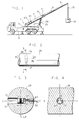
- Figure 1 illustrates, by way of example, the invention utilized in a truck mounted crane, although various other types of apparatus could also utilize the invention concepts, as noted above.
- a crane 1 has a base portion 3 connected to a truck body 5.
- the crane 1 has a base boom member 7 and two telescopically extensible boom members 9, 11.
- a load bearing cable 13 is suspended from the boom member 11 and is attached to a load 15.
- Base boom member 7 has a cable reeling drum 17 mounted thereon.
- the cable reeling drum 17 has a cable length sensor 19 mounted on it which generates a signal that corresponds to the overall length of boom members 7, 9, 11.
- the cable reeling drum 17 and cable length sensor 19 are well known in the art.
- An automatic cable reeling drum with a length sensing capability incorporated therein is the MCP/200 Series System manufactured by H. J. Tinsley and Company, Ltd.
- Base boom member 7 also has a processor unit shown schematically at 21 mounted thereon.
- An angle sensor 23 is attached to and in electrical communication with the processor unit 21.
- the angle sensor 23 generates an electric signal which is indicative of the angle of elevation of the base boom member 7 with respect to the crane base portion 3.
- the angle sensor 23 used is well known in the art and one such sensor is sold under the trademark "ACCUSTAR" and is manufactured by Lucas Sensing Systems, Inc.
- a main hydraulic cylinder 25 connects the base portion 23 to the base boom member 7, and is used to raise and lower the boom structure.
- the hydraulic cylinder 25 consists of a cylinder 27 and a piston rod 29.
- a strain sensor 31 centrally embedded within a bore hole 30 in the piston rod 29 is a strain sensor 31.
- the strain sensor 31 detects deformations in the bore hole 30 when the piston rod 29 is subjected to the force of the load 15. The strain sensor 31 then generates an electrical signal to the processor unit 21 which is indicative of the weight of the load 15.
- piston rod 29 is shown solid in the application drawing, it will be understood that partially or completely hollow pistons with partially or completely solid end support sections could also utilize the invention concepts. In such structure, the strain sensor could be embedded in the solid portion of the support section.
- the bore hole 30 comprises two counterbore sections 33 and 35 of varying diameter and concentric with a diametrical axis C-C through the piston.
- the counterbore 33 allows the strain sensor 31 to be inserted into the piston rod 29 using an insertion tool (not shown), with the strain sensor being press fitted into counterbore 35 preferably without prestressing the sensor.
- a cable 39 which is connected to the strain sensor 31, exits via a relatively smaller bore 37 and runs to the processor unit 21, thereby electrically connecting the sensor 31 to the processor unit 21.
- a strain reliever 40 having an axial bore is disposed in bore 37 to reduce the possibility of damage to sensor 31 from tension applied to cable 39.
- the strain sensor 31 is typically coated with a "Teflon" grease prior to insertion.
- the strain sensor 31 also has a knurled portion 41 on its outer periphery which improves the friction fit of the strain sensor 31 within counterbore 35.
- the axial center of the sensor is defined as the center of the knurled portion 41, and is aligned such that a longitudinal plane LP passing through the central longitudinal axis of the piston rod 29 also passes through the center of the knurled portion 41.
- the specific location of the bore hole 30 in the rod is not critical, with the rod being subjected to substantially uniform pressure over its entire length.
- the strain sensor 31 has two dimples or small projections 43 in the outer end thereof for ensuring proper alignment of the strain sensor 31 in the counterbore 35.
- Dimples 43 should preferably be positioned within plus or minus 3° of the load axis D-D, which is the central longitudinal axis of the piston rod 29, in order to achieve optimum results.
- the sensor could be rotated, for example 90°, and a useable signal would still be obtained.
- the strain sensor 31 When the strain sensor 31 is mounted as described above, the hydraulic irregularities and non-linearities encountered when attempting to measure cylinder pressure are resolved inside the cylinder and therefore the piston rod 29 and strain sensor 31 are only subject to the forces generated by the load 15 and the weight of the boom components. Therefore, the sensitivity and degree of accuracy of the present invention for determining the load being lifted is much greater than the prior art technique of sensing main cylinder hydraulic pressures.
- the present strain sensor installation overcomes the major flaw of tensiometers in that it responds immediately to the application of a load on the beam and therefore there is no lag time associated with this installation when determining the weight of the load.
- it is possible to sense an extreme overload and stop the machine before the structurally damaging load leaves the ground.
- strain sensor 31 is mounted in the piston rod 29, there is no need for an expensive cable reel or radio transmission device to send the strain sensor signal to the processor unit 21, as required for many of the weight determining devices discussed above. This is because the strain sensor 31 is located much closer to the processor unit 21 and connected thereto by a single cable length.
- the strain sensor 31 when the strain sensor 31 is located as described in the preferred embodiment, the weight of any additional items attached to the boom, jibs, or work baskets, is automatically detected by the strain sensor 31.
- the operator would have to remember to derate the maximum lifting capacity by the weight of each additional item in order to ensure that the proper maximum lifting capacity was calculated.
- strain sensor 31 is installed in the center of the piston rod 29 is also important in that temperature gradients between the sensor and the surrounding metal are minimized. Such temperature gradients can cause erroneous error indications and can be created, for example, if the sensor is mounted on the external surface of the piston rod 29 and exposed to direct sunlight. Additionally, by placing the sensor 31 in the center of the piston rod 29, the strain sensor 31 is precluded from erroneously measuring any side loading on the boom such as that created by the wind.
- strain sensor 31 A last important feature of the strain sensor 31 is that it can be safely inserted into the piston rod 29 without violating ANSI (American National Standards Institute) safety standards for the lift cylinder. Therefore, a major redesign of the whole crane structure is not required.
- ANSI American National Standards Institute
- the cable length sensor 19 and the angle sensor 23 provide signals to the processor unit 21 as noted in step S1.
- the processor unit 21 determines the radius from the center of rotation of the boom to the hook block and proceeds to identify a specific load zone in which the crane 1 is operating based on the calculated radius and the boom length.
- the processor unit 21 reads a load zone chart which is stored in memory. The load zone chart identifies discrete load zones for specific combinations of boom length and radius. Each load zone has a maximum load lifting capacity associated with it.
- the processor unit 21 reads the corresponding maximum load lifting capacity from the load zone chart, and in step S4, compares this value to the load indicated by the signal received from the strain sensor 31. If the load indicated by the strain sensor 31 is, for example, less than 90% of the maximum load lifting capacity, the program returns to step S2. If the load indicated by the strain sensor 31 is greater than or equal to 90%, and less than 100% of the maximum lifting capacity, a first warning light 45 and a first horn 47 are turned on. If the load indicated is greater than or equal to 100%, a second warning light 49 and second horn 51 are turned on. Finally, if the load indicated is greater than or equal to 105%, the overloading functions of telescoping the boom out, winching the load up, and lowering the boom will all be disabled. Obviously, the specific percentages of maximum load lifting capacity can be varied as desired, and can be more or less than the 90% and 105% indicated by way of example.
- An important advantage of dividing the load chart into discrete zones is that the processor unit 21 does not have to calculate as a continuous function the maximum lifting capacity for every point in space based on the crane's configuration. Rather, the computer only needs to determine which zone the machine is operating in. Thus, as long as the crane 1 is operating in that zone, there is only one maximum lifting capacity which the current load needs to be compared to until the crane moves into another zone of the load chart. This greatly reduces the computational load of the processor unit 21.
- processor unit 21 illustrated is preferred in the system disclosed, it will be understood that for more basic lift equipment, less sophisticated controls may be satisfactory. For example, in a single arm boom lift with a single rated capacity, a sensor and analog comparator for providing a comparison value triggering overload signaling of such type might be sufficient. In other words, the strain sensor of the invention can be utilized with a wide variety of equipment and controls, for the same purpose of preventing structural failure or tipping.
- strain sensors may be mounted in the lifting pistons of either or both booms to more precisely measure the load on each piston.
Landscapes
- Engineering & Computer Science (AREA)
- Mechanical Engineering (AREA)
- Jib Cranes (AREA)
- Control And Safety Of Cranes (AREA)
- Load-Engaging Elements For Cranes (AREA)
Claims (10)
- Lastmoment-Anzeigesystem für Förderzeug mit einer Trageinrichtung (3), einer relativ zu dieser bewegbaren Hubeinrichtung (7-11) und einer Zylinderanordnung (25) mit einem Zylinder (27) und einer mindestens teilweise massiven Kolbenstange (29) zum Heben und Senken der Hubeinrichtung (7-11), umfassendeinen Dehnungsfühler (31) zur Erzeugung eines das Gewicht einer Last (15) an der Hubeinrichtung (7-11) angebenden Signals,eine Einrichtung (21) zur Speicherung eines das maximale Lasthubvermögen der Hubeinrichtung (7-11) angebenden Wertes,eine Einrichtung (21), die das Signal mit dem Wert vergleicht, um zu bestimmen, ob das von dem Signal angegebene Gewicht der Last einen vorgegebenen Prozentsatz des das maximale Lasthubvermögen angebenden Wertes überschreitet, undeine Einrichtung (21) zur Ausgabe eines Ausgangssignals aufgrund des vorgegebenen Prozentsatzes, wobei das Ausgangssignal in Abhängigkeit vom Prozentsatz des maximalen Lasthubvermögens ein Alarmsignal auslöst und/oder die Hubeinrichtung abschaltet,
dadurch gekennzeichnet, daß der Dehnungsfühler (31) in einen massiven Teil der Kolbenstange (29) eingebettet ist. - System nach Anspruch 1, wobei der Dehnungsfühler (31) mittig in die Kolbenstange (29) eingebettet ist.
- System nach Anspruch 1 oder 2, wobei die Hubeinrichtung einen schwenkbar gelagerten Ausleger (7-11) mit meßbarem Winkel und meßbarer Länge aufweist, wobei die den Wert speichernde Einrichtung eine Prozessoreinheit (21) mit einer in ihrem Speicher vorhandenen Lastbereichskarte umfaßt, in der einzelne maximale Lasthubvermögen mit speziellen Kombinationen aus Auslegerwinkel und -länge korreliert sind, und wobei die Prozessoreinheit (21) aus der Lastbereichskarte das maximale Lasthubvermögen des Auslegers (7-11) in einem bestimmten Lastbereich ermittelt.
- System nach einem der Ansprüche 1 bis 3, wobei der Dehnungsfühler (31) in ein Querbohrloch (30) in der Stange (29) eingebettet und an einem in Längsrichtung mittleren Abschnitt seines Umfangs mit einer geriffelten Außenfläche (41) versehen ist, die auf eine durch die Kolbenstange (29) verlaufende erste Längsebene (LP) ausgerichtet ist.
- System nach einem der Ansprüche 1 bis 3, wobei der Dehnungsfühler (31) in einem die Stange (29) diametral durchsetzenden eine Bohrlochachse (C-C) aufweisenden Bohrloch (30) mit einem mittleren Bohrungsabschnitt (35) und einer äußeren erweiterten Gegenbohrung (33) montiert ist, wobei der Fühler (31) in dem mittleren Bohrungsabschnitt (35) konzentrisch zu der Bohrlochachse (C-C) reibschlüssig montiert ist, und wobei die Berührungsflächen des mittleren Bohrungsabschnitts (35) und des Dehnungsfühlers (31) so dimensioniert sind, daß der Fühler (31) reibschlüssig in dem mittleren Bohrungsabschnitt (35) sitzt.
- System nach Anspruch 5, wobei in zu der Gegenbohrung (33) entgegengesetzter Richtung ein Bohrungsabschnitt (37) verläuft, der einen kleineren Durchmesser aufweist als der mittlere Bohrungsabschnitt (35) und in dem eine Spannungsentlastung (40) zur spannungsfreien Aufnahme und Durchführung von Leitungen (39) von dem Dehnungsfühler (31) angeordnet ist.
- System nach Anspruch 4, ferner umfassend eine am außen freiliegenden Ende des Fühlers (31) vorgesehene Ausricht-Einrichtung (43), die eine Drehung des Fühlers (31) in dem Bohrloch (30) in seine optimale Orientierung relativ zu einer zu der ersten Längsebene (LP) senkrechten zweiten Längsebene (D-D) der Kolbenstange (29) gestattet.
- System nach einem der Ansprüche 3 bis 7, ferner umfassend eine Einrichtung (23) zur Erzeugung eines einen Winkel zwischen dem Ausleger (7-11) und der Trageinrichtung (3) angebenden ersten Signals, eine Einrichtung (19) zur Erzeugung eines eine Länge des Auslegers (7-11) angebenden zweiten Signals, eine erste Warnlampe (45) und eine erste Hupe (47), wobei die erste Lampe (45) und die erste Hupe (47) betätigt werden, wenn das Gewicht der Last entsprechend dem Ausgangssignal ≥ 90% aber < 100% des maximalen Lasthubvermögens ist.
- System nach Anspruch 8, ferner umfassend eine zweite Warnlampe (49) und eine zweite Hupe (51), wobei die zweite Lampe (49) und die zweite Hupe (51) betätigt werden, wenn das Gewicht der Last entsprechend dem Ausgangssignal ≥ 100% des maximalen Lasthubvermögens ist.
- System nach Anspruch 8 oder 9, wobei die eine Überlastung verursachenden Arbeitsfunktionen unmöglich gemacht werden, wenn das Gewicht der Last entsprechend dem Ausgangssignal ≥ 105% des maximalen Lasthubvermögens ist.
Applications Claiming Priority (2)
| Application Number | Priority Date | Filing Date | Title |
|---|---|---|---|
| US769783 | 1991-10-02 | ||
| US07/769,783 US5160055A (en) | 1991-10-02 | 1991-10-02 | Load moment indicator system |
Publications (2)
| Publication Number | Publication Date |
|---|---|
| EP0535339A1 EP0535339A1 (de) | 1993-04-07 |
| EP0535339B1 true EP0535339B1 (de) | 1997-07-23 |
Family
ID=25086489
Family Applications (1)
| Application Number | Title | Priority Date | Filing Date |
|---|---|---|---|
| EP92113747A Expired - Lifetime EP0535339B1 (de) | 1991-10-02 | 1992-08-12 | Lastmomentanzeigevorrichtung |
Country Status (7)
| Country | Link |
|---|---|
| US (1) | US5160055A (de) |
| EP (1) | EP0535339B1 (de) |
| JP (1) | JPH05278994A (de) |
| KR (1) | KR100197313B1 (de) |
| AU (1) | AU650359B2 (de) |
| CA (1) | CA2076949C (de) |
| DE (1) | DE69221057T2 (de) |
Families Citing this family (56)
| Publication number | Priority date | Publication date | Assignee | Title |
|---|---|---|---|---|
| US6006597A (en) * | 1993-02-15 | 1999-12-28 | Japan Electronics Industry, Limited | Wheel-acting force measuring device |
| US5538149A (en) * | 1993-08-09 | 1996-07-23 | Altec Industries, Inc. | Control systems for the lifting moment of vehicle mounted booms |
| US5359516A (en) * | 1993-09-16 | 1994-10-25 | Schwing America, Inc. | Load monitoring system for booms |
| PL310006A1 (en) * | 1993-11-26 | 1995-11-13 | Optimas Maschinenfabrik H Klei | Paving stone placing method and machine |
| JP4320931B2 (ja) * | 2000-03-27 | 2009-08-26 | コベルコクレーン株式会社 | クレーンの過負荷防止方法及び過負荷防止装置 |
| US6735486B2 (en) * | 2001-05-01 | 2004-05-11 | Altec Industries | Side load detection and protection system for rotatable equipment |
| US6871710B1 (en) | 2001-05-01 | 2005-03-29 | Altec Industries, Inc. | Rotational float for rotating equipment |
| US6991119B2 (en) | 2002-03-18 | 2006-01-31 | Jlg Industries, Inc. | Measurement system and method for assessing lift vehicle stability |
| US7014054B2 (en) | 2002-07-01 | 2006-03-21 | Jlg Industries, Inc. | Overturning moment measurement system |
| US6785597B1 (en) * | 2003-02-07 | 2004-08-31 | Wiggins Lift Co., Inc. | Hydraulic stabilizer system and process for monitoring load conditions |
| AU2005262296B2 (en) * | 2004-07-01 | 2011-06-02 | Great Stuff, Inc. | Systems and methods for controlling spooling of linear material |
| US7489098B2 (en) * | 2005-10-05 | 2009-02-10 | Oshkosh Corporation | System for monitoring load and angle for mobile lift device |
| US20080038106A1 (en) * | 2005-10-05 | 2008-02-14 | Oshkosh Truck Corporation | Mobile lift device |
| US7734399B2 (en) * | 2006-02-10 | 2010-06-08 | American Lafrance, Llc | Outrigger obstruction detection system for aerial fire trucks |
| US20070289738A1 (en) * | 2006-06-19 | 2007-12-20 | Kampman Rolf N | Rigless well intervention apparatus and method |
| US8561472B2 (en) | 2007-01-08 | 2013-10-22 | Precision Planting Llc | Load sensing pin |
| HUE034700T2 (hu) * | 2007-09-26 | 2018-02-28 | Prec Planting Llc | Rendszer és eljárás megfelelõ leszorító erõ meghatározására vetõgép soregységéhez |
| US20090200097A1 (en) * | 2008-02-12 | 2009-08-13 | Wiggins Lift Co., Inc. | Electronic steering system for a vehicle |
| US20090200116A1 (en) * | 2008-02-12 | 2009-08-13 | Wiggins Michael M | Multi-function joystick for forklift control |
| US20090200836A1 (en) * | 2008-02-12 | 2009-08-13 | Aaron Alls | Gusseted torsion system for an open frame vehicle |
| US20090200117A1 (en) * | 2008-02-12 | 2009-08-13 | Farber Bruce W | Slider scissor lift for a vehicle operator console |
| US8405721B2 (en) * | 2008-10-21 | 2013-03-26 | Motion Metrics International Corp. | Method, system and apparatus for monitoring loading of a payload into a load carrying container |
| US8272521B1 (en) * | 2009-10-05 | 2012-09-25 | Auto Crane Company | Crane moment load and load delivery system control and method |
| CN102575457B (zh) * | 2009-10-19 | 2014-12-17 | 日立建机株式会社 | 作业机械 |
| US20110153035A1 (en) * | 2009-12-22 | 2011-06-23 | Caterpillar Inc. | Sensor Failure Detection System And Method |
| CN102906347B (zh) * | 2010-05-24 | 2015-04-22 | 日立建机株式会社 | 作业机械的安全装置 |
| US8766812B2 (en) * | 2010-10-28 | 2014-07-01 | Us Tower Corporation | Tension sensor assembly |
| US9206026B2 (en) | 2010-11-12 | 2015-12-08 | Jlg Industries, Inc. | Longitudinal stability monitoring system |
| US8746605B2 (en) | 2011-04-19 | 2014-06-10 | Great Stuff, Inc. | Systems and methods for spooling and unspooling linear material |
| US8843279B2 (en) | 2011-06-06 | 2014-09-23 | Motion Metrics International Corp. | Method and apparatus for determining a spatial positioning of loading equipment |
| RU2012140237A (ru) * | 2011-09-23 | 2014-03-27 | МАНИТОВОК КРЕЙН КАМПЕНИЗ, ЭлЭлСи | Система и способы контроля выносных опор |
| US20140021284A1 (en) | 2012-07-20 | 2014-01-23 | Great Stuff, Inc. | Reel with manually actuated retraction system |
| US9327946B2 (en) * | 2012-07-16 | 2016-05-03 | Altec Industries, Inc. | Hydraulic side load braking system |
| LT3725141T (lt) | 2012-07-25 | 2022-10-10 | Precision Planting Llc | Žemės ūkio padargo prispaudimo jėgos valdiklis |
| DE102012221909A1 (de) * | 2012-11-29 | 2014-06-05 | Hirschmann Automation And Control Gmbh | Kabelbruchdiagnose bei einem Kran |
| US10410124B1 (en) * | 2013-01-21 | 2019-09-10 | Link-Belt Cranes, L.P., Lllp | Display for displaying lifting capacity of a lifting machine and related methods |
| FI124888B (fi) * | 2013-06-04 | 2015-03-13 | Ponsse Oyj | Menetelmä ja järjestely punnitusjärjestelmässä sekä vastaava ohjelmistotuote ja materiaalinkäsittelykone |
| DE102013014265A1 (de) * | 2013-08-27 | 2015-03-05 | Liebherr-Components Biberach Gmbh | Vorrichtung zur Erkennung der Ablegereife eines hochfesten Faserseils beim Einsatz an Hebezeugen |
| ES2537895B1 (es) * | 2013-11-14 | 2016-05-17 | Empresa De Transf Agraria S A (Tragsa) | Sistema y metodo para control de estabilidad en maquinaria pesada |
| CN106536944B (zh) * | 2014-06-18 | 2019-04-16 | 凯斯纽荷兰(中国)管理有限公司 | 安全液压回路 |
| FR3037681B1 (fr) * | 2015-06-18 | 2017-11-24 | Manitowoc Crane Group France | Procede de definition d’une courbe de charges optimisee pour grue, procede et dispositif de controle pour controler la charge suspendue a une grue a partir de la courbe de charges optimisee |
| US9771246B2 (en) * | 2015-08-31 | 2017-09-26 | Thomas Bond | Winch apparatus and method of use thereof |
| US10913639B2 (en) | 2017-02-06 | 2021-02-09 | LeRoy W. Mietzner, JR. | Boom safe anti-tip system |
| US11142442B2 (en) | 2017-02-10 | 2021-10-12 | Arrow Acquisition, Llc | System and method for dynamically controlling the stability of an industrial vehicle |
| US10782202B2 (en) | 2017-07-28 | 2020-09-22 | Brandt Industries Canada Ltd. | Load moment indicator system and method |
| US11319193B2 (en) | 2017-07-28 | 2022-05-03 | Brandt Industries Canada Ltd. | Monitoring system and method |
| US10427926B2 (en) * | 2017-12-22 | 2019-10-01 | Altec Industries, Inc. | Boom load monitoring |
| US10875753B2 (en) | 2018-09-20 | 2020-12-29 | Manitou Equipment America, Llc | Telehandler boom extension monitoring system |
| CN109132894B (zh) * | 2018-10-22 | 2020-12-08 | 徐州重型机械有限公司 | 起重设备 |
| US10994970B2 (en) | 2019-07-29 | 2021-05-04 | Jim D. Wiethorn | Crane risk logic apparatus and system and method for use of same |
| US11447373B2 (en) | 2019-09-27 | 2022-09-20 | Caterpillar Inc. | Lift capacity system for lifting machines |
| US11511976B2 (en) * | 2019-10-07 | 2022-11-29 | Caterpillar Inc. | System and method for determining a lifting capacity of a machine |
| US10913643B1 (en) | 2019-11-08 | 2021-02-09 | Altec Industries, Inc. | Dual boom load monitoring |
| FR3123908B1 (fr) * | 2021-06-14 | 2023-10-27 | Manitowoc Crane Group France | Procédé de sécurisation d’une grue à la survenue d’un évènement exceptionnel |
| CN113860170B (zh) * | 2021-09-02 | 2024-10-22 | 徐工集团工程机械股份有限公司建设机械分公司 | 一种吊管机安全控制系统及方法 |
| GB2618581A (en) * | 2022-05-11 | 2023-11-15 | Caterpillar Inc | Safety control unit for a lifting arm machine |
Family Cites Families (24)
| Publication number | Priority date | Publication date | Assignee | Title |
|---|---|---|---|---|
| US2477854A (en) * | 1945-06-16 | 1949-08-02 | Black & Decker Mfg Co | Hydraulic jack weighing device |
| US2616683A (en) * | 1947-03-17 | 1952-11-04 | Griffiths & Sprague Stevedorin | Mechanism for weighing bulk cargo |
| DE1017982B (de) * | 1954-04-01 | 1957-10-17 | Emmanuel Kaye | Hubkarren mit Belastungsanzeiger |
| US3339652A (en) * | 1966-09-26 | 1967-09-05 | Robert J Price | Load weight indicator installation for cranes, derricks and the like |
| US3641551A (en) * | 1968-12-19 | 1972-02-08 | Grove Mfg Co | Safe load control system for telescopic crane booms |
| US3638211A (en) * | 1969-10-08 | 1972-01-25 | Litton Systems Inc | Crane safety system |
| US3713129A (en) * | 1970-03-30 | 1973-01-23 | R Buchholz | Crane overloading protective system |
| US3680714A (en) * | 1970-07-22 | 1972-08-01 | Case Co J I | Safety device for mobile cranes |
| US3724679A (en) * | 1971-02-19 | 1973-04-03 | Clark Equipment Co | Indicator or control for cranes |
| US4039084A (en) * | 1971-07-06 | 1977-08-02 | Tadano Ironworks Co., Ltd. | Safety-guard for a crane |
| US4058178A (en) * | 1971-09-13 | 1977-11-15 | Tadano Ironworks Co., Ltd. | Hydraulic cylinder unit |
| DE2400243A1 (de) * | 1974-01-04 | 1975-07-17 | Irion & Vosseler | Sicherheitseinrichtung fuer gabelstapler |
| GB1528741A (en) * | 1974-10-12 | 1978-10-18 | Liner Concrete Machinery | Load handling vehicle |
| US4003487A (en) * | 1975-04-03 | 1977-01-18 | Allis-Chalmers Corporation | Truck overload protective system having trip signal sampling means |
| DE2659755B2 (de) * | 1976-12-31 | 1978-10-12 | Krueger & Co Kg, 4300 Essen | Vorrichtung zum Abgeben eines Sollwertsignals für eine Überwachungseinrichtung eines Auslegerkranes o.dgl |
| FR2378272A1 (fr) * | 1977-01-25 | 1978-08-18 | Ferodo Sa | Dispositif dynamometrique de mesure de couple pour engin a fleche de levage a commande par verin |
| US4222491A (en) * | 1978-08-02 | 1980-09-16 | Eaton Corporation | Crane operating aid and sensor arrangement therefor |
| US4395706A (en) * | 1980-06-30 | 1983-07-26 | Jlg Industries, Inc. | Boom limit safety control circuit |
| GB2112940B (en) * | 1982-01-05 | 1985-11-20 | Safety Devices | Displaying the axle load or working load of a vehicle |
| AU1534983A (en) * | 1982-10-12 | 1984-04-19 | Jlg Industries, Inc. | Load measuring apparatus |
| EP0154728B1 (de) * | 1984-03-13 | 1988-11-02 | Yotaro Hatamura | Lastdetektor |
| US4752012A (en) * | 1986-08-29 | 1988-06-21 | Harnischfeger Corporation | Crane control means employing load sensing devices |
| IT1204913B (it) * | 1987-03-06 | 1989-03-10 | 3B6 Sistemi Elettro Idraulici | Dispositivo limitatore di sbraccio e/o di momento per piataforme elevatrici |
| GB8818074D0 (en) * | 1988-07-29 | 1988-09-01 | Markload Systems Ltd | Monitoring system for load carriers |
-
1991
- 1991-10-02 US US07/769,783 patent/US5160055A/en not_active Expired - Lifetime
-
1992
- 1992-08-12 EP EP92113747A patent/EP0535339B1/de not_active Expired - Lifetime
- 1992-08-12 DE DE69221057T patent/DE69221057T2/de not_active Expired - Lifetime
- 1992-08-13 AU AU20997/92A patent/AU650359B2/en not_active Expired
- 1992-08-26 CA CA002076949A patent/CA2076949C/en not_active Expired - Lifetime
- 1992-09-22 JP JP4277847A patent/JPH05278994A/ja active Pending
- 1992-10-01 KR KR1019920017990A patent/KR100197313B1/ko not_active Expired - Fee Related
Also Published As
| Publication number | Publication date |
|---|---|
| AU2099792A (en) | 1993-04-08 |
| KR100197313B1 (ko) | 1999-06-15 |
| US5160055A (en) | 1992-11-03 |
| KR930007792A (ko) | 1993-05-20 |
| EP0535339A1 (de) | 1993-04-07 |
| CA2076949A1 (en) | 1993-04-03 |
| AU650359B2 (en) | 1994-06-16 |
| DE69221057D1 (de) | 1997-09-04 |
| JPH05278994A (ja) | 1993-10-26 |
| DE69221057T2 (de) | 1998-01-29 |
| CA2076949C (en) | 1996-02-20 |
Similar Documents
| Publication | Publication Date | Title |
|---|---|---|
| EP0535339B1 (de) | Lastmomentanzeigevorrichtung | |
| US6843383B2 (en) | Jib load limiting device | |
| US6439341B1 (en) | Apparatus for monitoring loading of a lift | |
| EP0728696A1 (de) | Vorrichtung zum detektieren von last- und kippmoment für einen beweglichen kran | |
| US10006821B1 (en) | Deflection detection system utilizing an energized beam | |
| US8779306B2 (en) | Weight sensing method and apparatus for forklifts | |
| SU793371A3 (ru) | Кран | |
| US9873602B2 (en) | Boom protection system | |
| US6044991A (en) | Load measuring apparatus for aerial booms and jibs | |
| EP3409635B1 (de) | Wiegesystem für eine hebevorrichtung | |
| EP1150019B1 (de) | Zähler für Hebevorgänge von Kränen | |
| CN112299251A (zh) | 改进的具有两个或更多个吊钩的臂 | |
| CN215626268U (zh) | 配重监测系统、臂架监测系统、吊载安全监测系统及起重设备 | |
| KR100416395B1 (ko) | 크레인 과부하 방지장치 | |
| RU2271332C2 (ru) | Способ защиты стрелового грузоподъемного крана | |
| EP0358343A1 (de) | Kran mit Überlastdetektor | |
| GB2187708A (en) | An apparatus for monitoring the forces acting during operation on a working cage | |
| EP1491485B1 (de) | Kran mit einer Seilwinde und mit einer Zugsteuereinrichtung | |
| RU18171U1 (ru) | Ограничитель грузоподъемности для подъемных люлек со стержневой подвеской | |
| EP1477452B1 (de) | Verfahren und Vorrichtung zum Ermitteln der Last eines Kranauslegers | |
| KR200270085Y1 (ko) | 크레인 과부하 방지장치 | |
| EP1798188B1 (de) | Hydraulischer Kran und Verfahren für die Registrierung. | |
| RU2810831C2 (ru) | Усовершенствованная стрела с двумя или более крюками | |
| JP7088418B2 (ja) | 過負荷防止装置 | |
| RU56887U1 (ru) | Система безопасности грузоподъемного крана |
Legal Events
| Date | Code | Title | Description |
|---|---|---|---|
| PUAI | Public reference made under article 153(3) epc to a published international application that has entered the european phase |
Free format text: ORIGINAL CODE: 0009012 |
|
| AK | Designated contracting states |
Kind code of ref document: A1 Designated state(s): AT BE CH DE DK ES FR GB GR IT LI LU MC NL PT SE |
|
| RBV | Designated contracting states (corrected) |
Designated state(s): DE GB IT NL |
|
| 17P | Request for examination filed |
Effective date: 19930903 |
|
| GRAG | Despatch of communication of intention to grant |
Free format text: ORIGINAL CODE: EPIDOS AGRA |
|
| 17Q | First examination report despatched |
Effective date: 19960812 |
|
| GRAH | Despatch of communication of intention to grant a patent |
Free format text: ORIGINAL CODE: EPIDOS IGRA |
|
| GRAH | Despatch of communication of intention to grant a patent |
Free format text: ORIGINAL CODE: EPIDOS IGRA |
|
| GRAA | (expected) grant |
Free format text: ORIGINAL CODE: 0009210 |
|
| AK | Designated contracting states |
Kind code of ref document: B1 Designated state(s): DE GB IT NL |
|
| REF | Corresponds to: |
Ref document number: 69221057 Country of ref document: DE Date of ref document: 19970904 |
|
| PLBE | No opposition filed within time limit |
Free format text: ORIGINAL CODE: 0009261 |
|
| 26N | No opposition filed | ||
| REG | Reference to a national code |
Ref country code: GB Ref legal event code: IF02 |
|
| PGFP | Annual fee paid to national office [announced via postgrant information from national office to epo] |
Ref country code: GB Payment date: 20110722 Year of fee payment: 20 Ref country code: DE Payment date: 20110831 Year of fee payment: 20 |
|
| PGFP | Annual fee paid to national office [announced via postgrant information from national office to epo] |
Ref country code: NL Payment date: 20110812 Year of fee payment: 20 Ref country code: IT Payment date: 20110816 Year of fee payment: 20 |
|
| REG | Reference to a national code |
Ref country code: DE Ref legal event code: R071 Ref document number: 69221057 Country of ref document: DE |
|
| REG | Reference to a national code |
Ref country code: DE Ref legal event code: R071 Ref document number: 69221057 Country of ref document: DE |
|
| REG | Reference to a national code |
Ref country code: NL Ref legal event code: V4 Effective date: 20120812 |
|
| REG | Reference to a national code |
Ref country code: GB Ref legal event code: PE20 Expiry date: 20120811 |
|
| PG25 | Lapsed in a contracting state [announced via postgrant information from national office to epo] |
Ref country code: DE Free format text: LAPSE BECAUSE OF EXPIRATION OF PROTECTION Effective date: 20120814 Ref country code: GB Free format text: LAPSE BECAUSE OF EXPIRATION OF PROTECTION Effective date: 20120811 |