EP3769700B1 - Vorrichtung zum stauen von gefässen - Google Patents
Vorrichtung zum stauen von gefässen Download PDFInfo
- Publication number
- EP3769700B1 EP3769700B1 EP20195651.3A EP20195651A EP3769700B1 EP 3769700 B1 EP3769700 B1 EP 3769700B1 EP 20195651 A EP20195651 A EP 20195651A EP 3769700 B1 EP3769700 B1 EP 3769700B1
- Authority
- EP
- European Patent Office
- Prior art keywords
- closure
- constricting belt
- belt
- constricting
- tourniquet
- Prior art date
- Legal status (The legal status is an assumption and is not a legal conclusion. Google has not performed a legal analysis and makes no representation as to the accuracy of the status listed.)
- Active
Links
Images


Classifications
-
- A—HUMAN NECESSITIES
- A61—MEDICAL OR VETERINARY SCIENCE; HYGIENE
- A61B—DIAGNOSIS; SURGERY; IDENTIFICATION
- A61B17/00—Surgical instruments, devices or methods
- A61B17/12—Surgical instruments, devices or methods for ligaturing or otherwise compressing tubular parts of the body, e.g. blood vessels or umbilical cord
- A61B17/132—Tourniquets
- A61B17/1322—Tourniquets comprising a flexible encircling member
- A61B17/1327—Tensioning clamps
-
- A—HUMAN NECESSITIES
- A61—MEDICAL OR VETERINARY SCIENCE; HYGIENE
- A61B—DIAGNOSIS; SURGERY; IDENTIFICATION
- A61B17/00—Surgical instruments, devices or methods
- A61B17/12—Surgical instruments, devices or methods for ligaturing or otherwise compressing tubular parts of the body, e.g. blood vessels or umbilical cord
- A61B17/132—Tourniquets
- A61B17/1322—Tourniquets comprising a flexible encircling member
-
- A—HUMAN NECESSITIES
- A61—MEDICAL OR VETERINARY SCIENCE; HYGIENE
- A61B—DIAGNOSIS; SURGERY; IDENTIFICATION
- A61B17/00—Surgical instruments, devices or methods
- A61B17/12—Surgical instruments, devices or methods for ligaturing or otherwise compressing tubular parts of the body, e.g. blood vessels or umbilical cord
- A61B17/132—Tourniquets
- A61B17/135—Tourniquets inflatable
-
- A—HUMAN NECESSITIES
- A61—MEDICAL OR VETERINARY SCIENCE; HYGIENE
- A61B—DIAGNOSIS; SURGERY; IDENTIFICATION
- A61B5/00—Measuring for diagnostic purposes; Identification of persons
- A61B5/02—Detecting, measuring or recording for evaluating the cardiovascular system, e.g. pulse, heart rate, blood pressure or blood flow
- A61B5/021—Measuring pressure in heart or blood vessels
- A61B5/022—Measuring pressure in heart or blood vessels by applying pressure to close blood vessels, e.g. against the skin; Ophthalmodynamometers
- A61B5/02233—Occluders specially adapted therefor
-
- A—HUMAN NECESSITIES
- A61—MEDICAL OR VETERINARY SCIENCE; HYGIENE
- A61B—DIAGNOSIS; SURGERY; IDENTIFICATION
- A61B5/00—Measuring for diagnostic purposes; Identification of persons
- A61B5/68—Arrangements of detecting, measuring or recording means, e.g. sensors, in relation to patient
- A61B5/6801—Arrangements of detecting, measuring or recording means, e.g. sensors, in relation to patient specially adapted to be attached to or worn on the body surface
- A61B5/683—Means for maintaining contact with the body
- A61B5/6831—Straps, bands or harnesses
-
- A—HUMAN NECESSITIES
- A61—MEDICAL OR VETERINARY SCIENCE; HYGIENE
- A61B—DIAGNOSIS; SURGERY; IDENTIFICATION
- A61B17/00—Surgical instruments, devices or methods
- A61B2017/00017—Electrical control of surgical instruments
- A61B2017/00022—Sensing or detecting at the treatment site
-
- A—HUMAN NECESSITIES
- A61—MEDICAL OR VETERINARY SCIENCE; HYGIENE
- A61B—DIAGNOSIS; SURGERY; IDENTIFICATION
- A61B17/00—Surgical instruments, devices or methods
- A61B2017/00477—Coupling
-
- A—HUMAN NECESSITIES
- A61—MEDICAL OR VETERINARY SCIENCE; HYGIENE
- A61B—DIAGNOSIS; SURGERY; IDENTIFICATION
- A61B17/00—Surgical instruments, devices or methods
- A61B2017/00831—Material properties
- A61B2017/0084—Material properties low friction
- A61B2017/00845—Material properties low friction of moving parts with respect to each other
-
- A—HUMAN NECESSITIES
- A61—MEDICAL OR VETERINARY SCIENCE; HYGIENE
- A61B—DIAGNOSIS; SURGERY; IDENTIFICATION
- A61B17/00—Surgical instruments, devices or methods
- A61B2017/00831—Material properties
- A61B2017/00853—Material properties low friction, hydrophobic and corrosion-resistant fluorocarbon resin coating (ptf, ptfe, polytetrafluoroethylene)
-
- A—HUMAN NECESSITIES
- A61—MEDICAL OR VETERINARY SCIENCE; HYGIENE
- A61B—DIAGNOSIS; SURGERY; IDENTIFICATION
- A61B17/00—Surgical instruments, devices or methods
- A61B2017/00831—Material properties
- A61B2017/00862—Material properties elastic or resilient
-
- A—HUMAN NECESSITIES
- A61—MEDICAL OR VETERINARY SCIENCE; HYGIENE
- A61B—DIAGNOSIS; SURGERY; IDENTIFICATION
- A61B17/00—Surgical instruments, devices or methods
- A61B2017/00831—Material properties
- A61B2017/00876—Material properties magnetic
-
- A—HUMAN NECESSITIES
- A61—MEDICAL OR VETERINARY SCIENCE; HYGIENE
- A61B—DIAGNOSIS; SURGERY; IDENTIFICATION
- A61B17/00—Surgical instruments, devices or methods
- A61B2017/00831—Material properties
- A61B2017/00942—Material properties hydrophilic
-
- A—HUMAN NECESSITIES
- A61—MEDICAL OR VETERINARY SCIENCE; HYGIENE
- A61B—DIAGNOSIS; SURGERY; IDENTIFICATION
- A61B90/00—Instruments, implements or accessories specially adapted for surgery or diagnosis and not covered by any of the groups A61B1/00 - A61B50/00, e.g. for luxation treatment or for protecting wound edges
- A61B90/08—Accessories or related features not otherwise provided for
- A61B2090/0807—Indication means
- A61B2090/081—Indication means for contamination or dirt
-
- A—HUMAN NECESSITIES
- A61—MEDICAL OR VETERINARY SCIENCE; HYGIENE
- A61B—DIAGNOSIS; SURGERY; IDENTIFICATION
- A61B90/00—Instruments, implements or accessories specially adapted for surgery or diagnosis and not covered by any of the groups A61B1/00 - A61B50/00, e.g. for luxation treatment or for protecting wound edges
- A61B90/08—Accessories or related features not otherwise provided for
- A61B2090/0813—Accessories designed for easy sterilising, i.e. re-usable
-
- A—HUMAN NECESSITIES
- A61—MEDICAL OR VETERINARY SCIENCE; HYGIENE
- A61B—DIAGNOSIS; SURGERY; IDENTIFICATION
- A61B2562/00—Details of sensors; Constructional details of sensor housings or probes; Accessories for sensors
- A61B2562/24—Hygienic packaging for medical sensors; Maintaining apparatus for sensor hygiene
Definitions
- This invention relates to a hygienic device for storing vessels (vascular tourniquet) with a storage band, which is connected to a closed round band using a closure.
- vascular tourniquet also known as a tourniquet or tourniquet, is used in medicine.
- Vascular tourniquets are used to achieve compression, for example to create back pressure in blood vessels, e.g. B. when taking blood or when setting other accesses, or to enable a blood vessel to be temporarily blocked for a blood pressure measurement.
- a vascular tourniquet is applied before each blood sample is taken. Tightening the vascular tourniquet causes blood to congest in the veins, making them more visible and easier to puncture with a cannula. Such a procedure often takes place several times a day for inpatients. Cleaning is necessary after each use.
- vascular tourniquets consist mainly of an elastic terry-like band and a two-part closure element. Due to the mechanical configuration of the closure, the surface has many indentations and moving parts that represent germ reservoirs.
- the current cleaning instructions of the manufacturers of such vascular tourniquets to ensure hospital hygiene stipulate that these vascular tourniquets are treated in an autoclaving device. This requires an approximately 2-hour procedure consisting of pressure, steam, heat and radiation treatment.
- the storage belt and the closure parts in particular represent germ reservoirs, as both have a large, rough surface that is difficult to clean. Accordingly, vascular tourniquets of this type must be treated in an autoclaving device to enable them to be freed from germs. Macroscopic, including visually visible, contamination is difficult or impossible to remove from the tape; textile components and a woven structure exclude other cleaning options, such as wiping off blood stains.
- a tourniquet ligation system as in WO 2016/172599 A1 shown describes a buckle for a constriction bandage through which the blood flow is to be stopped by putting pressure on a blood vessel in order to avoid extreme blood loss.
- magnetic holding devices are used, among other things.
- the tie-off bandage connected to it is tied tightly around the part of the body to be tied off.
- the bar is then fixed to the buckle using a tab, buttons or a magnetic lock.
- a Clamping therefore takes place independently of the magnetic lock.
- the safety can only maintain the toggle pressure previously built up by a rod and prevent the rod from turning back.
- the design of the band and the tensioning and holding mechanism with many individual parts and hidden edges represent germ reservoirs that prevent low-germ work in everyday clinical practice.
- the US 2008/262535 A1 discloses a mechanized tourniquet designed to stop arterial blood loss in an injured limb.
- the tourniquet is activated either by a user or automatically.
- the tourniquet and its electromechanical tensioning device are automatically controlled by a band tension control mechanism and a timer initialized by a safety signal.
- the WO 2018/008607 A1 reveals a hemostatic instrument.
- the instrument includes a band to be wrapped around a wrist, a fixation means for fixing the band in a wrapped state around the wrist, an expanding unit that expands by introducing air and presses against the site where bleeding is to be stopped.
- the GB 2 540 197 A discloses a tourniquet comprising a strip formed from foil material.
- the strip has a first end and a second end.
- the strip defines an opening toward the first end and has a portion adjacent the second end configured to extend through the opening.
- the tourniquet has a plurality of locking elements spaced along the section.
- the locking elements extend from the section and are configured to allow the section to pass through the opening.
- the locking elements are further designed to provide resistance to the section protruding from the opening.
- the WO 2014/191987 A1 discloses a compressed gas container and a flow control unit within a rigid housing of a control device.
- the control device is attached to an inflatable strap of a pneumatic tourniquet.
- the flow control unit is configured to selectively direct a dose of the compressed gas delivered from the gas container into an inner belt chamber to achieve a predetermined chamber pressure for applying a required hemorrhage-suppressing force to a limb.
- the US 2011/247179 A1 discloses a latch device for clamping a band.
- the latch includes first and second latch members engaged to pivot relative to one another.
- the US 2010/063206 discloses a method and apparatus for fluorinating plastics.
- the EP 2 745 785 discloses a vascular closure system that can be glued in a location-defined manner for closing open blood vessels.
- the invention is based on the object of designing the closure and in particular the storage band of a vascular tourniquet in such a way that it can be used as a hygienic, reusable tourniquet can be carried out by making it possible to carry out a simpler disinfection option, such as spraying/wiping disinfection on site, in order to avoid the spread of germs. Furthermore, it is the object of the invention that the closure elements find their locking position independently even if they are joined together inaccurately. The fastener should be able to be put together and released with one hand.
- the device described here for stowing vessels comprises a storage band, preferably with a width between 0.5 and 50 cm, preferably between 1 and 10 cm for one embodiment, for example as a vessel stowage, and between 7 and 30 cm for a further embodiment, for example as a blood pressure cuff, and a closure which contains two closure elements, one end of the storage band being firmly connectable to one closure element of the closure and the other closure element being slidably disposed on the storage band.
- the storage band and the closure can be made of a material with a smooth surface. When closed, the closure can be a smooth, cuboid or elongated body which, apart from the feeds for the storage belt, has no further external openings and no external shoulders due to flush edges between the closure elements.
- Flush also means that the final edges are largely flush, i.e. they can also be conical or convex, for example.
- the dust band is made of a textile-free material and the dust band and optionally the closure are provided with a slip coating by fluorinating their surface.
- the anti-friction coating can seal the surface(s).
- Textiles reach a maximum stretch due to the arrangement of the stitches. This causes constriction effects to occur more quickly, resulting in soft tissue bruising and thrombosis. Due to the intermolecular effects, a rubber band does not have such a pronounced maximum, which prevents pinching and allows for softer adjustment options for the dynamic pressure.
- the dust band can also be made of another elastic material with a closed surface, such as. E.g. latex, thermoplastic elastomers, Teflon or similar.
- a locking device for the storage band is provided in one closure element.
- the movable closure element can be magnetically connected to the fixed closure element.
- one closure element is provided with webs and springs on at least one, preferably at least two outer edges on a side facing the other closure element
- the other closure element is provided with webs and springs on at least one, preferably at least two outer edges, and both closure elements are on the outer edges are flush with each other when closed.
- the chamfers of one closure element correspond to the webs of the other closure element and the grooves of one closure element correspond to the springs of the other closure element.
- a sensor system for determining vital parameters such as heart rate/pulse, blood pressure, blood oxygen level, and/or an activity cleaning state in the dust band, such as status by magnetic sensor: open/closed, proximity to the cleaning location, strain gauges, and /or the closure, for example a magnetic sensor, light, sound or strain sensor can be used here.
- a further embodiment integrates a transmitting and receiving unit in the storage band and/or in the closure, which enables the forwarding of information that was determined, for example, by the sensor system.
- the closure according to the invention for a device for stowing vessels has at least two closure elements which are detachably connected to one another.
- One closure element is fixed with a storage band and the other closure element is displaceably arranged on the storage band.
- the closure elements are provided with chamfers and grooves and corresponding webs and tongues in accordance with the claim and are designed flush with one another on their outer edges.
- the webs with the tongues or the bevels with the grooves are connected to the movable or the fixed closure element.
- the webs are arranged on the closure element at an angle to the closure element. It is conceivable that both webs are inclined at an angle other than 90 degrees in the same direction or in an opposite direction.
- the angle between the webs and the closure elements should be between 30 and 150 degrees, preferably around 80 degrees.
- the detachable connection can be made, for example, by a magnetic lock.
- the webs are arcuate (curved) in the direction of the opposite closure element and the bevels are designed to correspond to the webs.
- the webs on the closure element are slightly wider in such a way that the webs have a base and a tip, the base being at least 0.1 mm, preferably 0.5 mm to 5 mm, wider than the tip, and the chamfers are designed to correspond to the webs, so that a simple sliding interaction between the two closure elements is guaranteed, which can be further improved by at least one flexible web.
- Magnets are connected to the closure elements, which act with their magnetic fields between the two closure elements and which pull the closure elements into one another due to their opposite polarity, which results in a locking.
- the magnetic force of the connected closure elements can also initiate the locking mechanism and lock the band when the closure is closed (in one direction).
- a repulsive magnetic field can act on the fourth outer edge of the first closure element, thereby accelerating the release of both closure elements from one another.
- the magnetic field can also be operated electronically, for example to specifically regulate the field strength of the magnetic field or to be able to adjust the sensors. This also makes it possible to switch off the electronics, for example after use.
- a locking device with a surface relief is arranged within the one closure element, which is a precisely fitting counterpart to a storage band which is provided with a corresponding surface relief.
- a lever or a wheel can also be arranged on the closure in order to create additional tension on the storage band.
- a blood pressure cuff can use a device for damming vessels according to the solution according to the invention and be connected to a closure according to the invention.
- the device according to the invention for stowing vessels enables a simpler process of use with improved hygiene properties.
- the improved usability for the user is made possible by one-handed operation throughout the entire process. Due to the magnetic force in the closure, the entire closure mechanism is carried out virtually independently. The closure, so to speak, finds itself.
- the magnets can be incorporated into the closure so as not to form the surface of the closure.
- Opening the shutter begins with a movement directed across the storage band, for example a simple swiping movement of the thumb (like unlocking a smartphone). Due to the web shape, the opening process can also be carried out in a curved movement. After overcoming the magnetic potential maximum, which serves to secure the closure, repulsive forces can support the opening process of the closure.
- the smooth parts of the tourniquet and the closure significantly simplify and improve faster cleaning and the release of germs on the tourniquet.
- the creation of a germ reservoir is prevented by moving the movable external closure parts into the interior, so that there are no prominent/uneven places for germs to accumulate.
- An indoor device can also ensure that the vascular tourniquet cleans itself without external measures.
- One embodiment would be a deflection roller made of ionic-bactericidal materials. Autoclaving or other technical sterilization measures are no longer necessary.
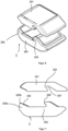
- the Figures 1 to 3 show the device according to the invention for stowing vessels in various perspective views and in a side view with an opened closure.
- the device according to the invention for stowing vessels consists of an elastic storage band 1 with a smooth surface, for example made of a textile-free silicone material.
- the storage band 1 is connected to a closure 2 so that it can be connected to a closed round band.
- the closure 2 consists of at least two closure elements 201 and 202, which are releasably connected by means of a magnetic lock.
- the closure 2 in the closed state apart from the final edge between the closure elements, is a smooth, cuboid or elongated body with preferably rounded edges, which, apart from the feeds for the storage belt 1, has no further external openings or shoulders, since the edges between one first, fixed closure element 201 and a second, movable closure element 202 are flush.
- Other final edges e.g. between the upper and lower shells due to manufacturing technology, are negligible as openings.
- the first, upper closure element 201 is arranged in such a way that the storage band 1 is threaded into this closure element 201 and is secured, for example, by gluing, pressure, screws or magnetically, so that the storage band 1 is firmly connected to the Closure element 201 is connected.
- the second end 102 of the storage band 1 is in a designated, through the second, lower, displaceable closure element 202 and limited at its end 102 by a stop mechanism 103 so that the closure element 202, which can be moved on the smooth elastic storage belt 1, cannot slide off the storage belt 1.
- a locking device 205 for example in the form of a slide rail, with a locking mechanism, for example a rocker, a wedge, a spring, a roughened surface or a pressure roller, is provided for the storage belt 1.
- the movable closure element 202 is magnetically connectable to the fixed closure element 201 and automatically locks mechanically. After the two closure elements 201, 202 have been connected to one another, the locking device is automatically actuated by the tensioning process around an object.
- a magnetic locking mechanism is used for the magnetic connection of both closure elements 201, 202.
- the special design of the closure 2 according to the invention makes it possible to close, tighten and open the storage band 1 with one hand.
- a closed closure 2 is shown.
- a magnet 3 is incorporated in each closure part 201, 202 in the middle and facing each other.
- One of the two closure elements 201, 202 is provided with webs 203 transversely to the storage band 1 on several, for example two, outer edges on the side facing the other closure element 201.
- the webs 203 are provided with springs 206 at their upper end, pointing into the interior of the closure.
- the first closure element 201 is designed such that both closure elements 201, 202 can mesh with one another.
- the first closure element 201 is provided with a front and a rear chamfer 207 on, for example, two outer edges. Grooves 204, which correspond to the springs 206, are incorporated into two outward-facing surfaces of the chamfers 207.
- the springs 206 engage in the grooves 204 and thus enable additional security.
- the third and fourth outer edges, preferably in the longitudinal direction of the storage band 1, are designed flush with the other closure element 201, 202.
- the webs 203 and the springs 206 can be connected to the movable or the fixed closure element 201, 202. The same applies to the grooves 204 and the chamfers 207 in a corresponding manner to the springs 206 and webs 203.
- the webs 203 are arranged on the closure element 201, 202 in this exemplary embodiment at a right angle to the closure element 201, 202.
- the angle between the webs 203 and the closure elements 201, 202 should be between 30 and 150 degrees, preferably around 80 degrees.
- the webs 203 on the closure element 201, 202 have a base 203a and a tip 203b, the base 203a being at least 0.1 mm , preferably 0.5 mm to 5 mm wider than the tip 203b.
- the bevels 207 are designed accordingly, so that in any case a simple sliding interaction between the two closure elements 201, 202 with one another is guaranteed. Thanks to the magnets 3 located inside the closure 2, both closure elements 201, 202 find themselves when they come into the effective range of the magnetic field. One-handed operation (application, tensioning, loosening and releasing) of the storage band 1 is possible.
- both closure elements 201, 202 To release both closure elements 201, 202 from each other, the upper closure element 201 is pushed, for example with the thumb, in the direction in which there is no web 203 on the lower closure element 202, which means that several directions are conceivable. The movement continues until the attractive effect of the magnets 3 decreases and both closure elements 201, 202 separate from one another due to the (possible) repulsive effect that begins.
- the storage band 1 and optionally the closure 2 are provided with a smoothing coating by fluorinating its surface(s).
- the extraordinary smoothness of the storage band and/or the closure is achieved by the special coating.
- hydrogen atoms are removed from the side chains and replaced with fluorine, which changes the surface properties.
- the static and sliding friction as well as the stickiness are significantly reduced, and on the other hand, the wettability is increased, so that polar liquids, as in liquid disinfection, form a special surface film and no longer tend to form local drops due to their own polarity.
- This coating can be tested by a tilt test in which the coated material and the uncoated material lie on a plane that is at 0° and can be tilted smoothly/continuously up to 100°.
- the one described here Dust tape reaches less than 35° for hygiene purposes when it begins to slide.
- Figure 5 shows a blood pressure cuff 4 with a device for damming vessels as a further exemplary embodiment.
- a smooth band 5 is connected in the manner described to the closure 2 described in detail above, which can be dimensioned larger for this application than for the storage band 1.
- the variable pressure adjustment can, as is usual in the prior art, be carried out using different mechanisms, the most common being the pneumatic pressure increase using a pump.
- Figures 6 and 7 shows the closure 2 with arcuate webs 203, which engage in correspondingly shaped grooves 204, whereby the closure elements 201, 202 are better held together by the force transmission when pulled.
- the magnets 3 are located within the closure 2 in this embodiment.
- the rounding of the interlocking arcuate webs 203 contributes to the shear forces acting in a larger circular segment than with exclusively straight edge guidance. This ensures that the closure elements 201, 202 are held securely to one another and the holding forces of the magnetic potential maximum are supported.
- Fasteners 2 can also be used for this, which are only intended for tightening and loosening, and may not even be able to be opened, but can only be slipped over the arm, but have the hygienic properties of the invention mentioned and have an appropriate anti-friction coating.
- sensors into the vascular tourniquet described above, such as strain gauges or fibers that resistively detect changes in length in the tourniquet band 1 or in the band 5.
- the measurement of blood pressure or other vital parameters can be carried out with the help of the already existing tensioning mechanism, in that the necessary pretension is generated by the device according to the invention for damming vessels. The preload then no longer needs to be varied by pumping.
- blood pressure can be recorded, among other things, which represents a new type of blood pressure measurement method.
- Appropriate sensors in the vascular tourniquet or blood pressure cuff can also help to record the cleaning status.
- a transmitting and receiving unit is integrated in the storage band 1 and/or in the closure 2, which enables the forwarding of information.
- a transmitting and receiving unit is integrated in the storage band 1 and/or in the closure 2, which enables the forwarding of information.
- the hygienic condition of the vascular tourniquet and the vital parameters can be transmitted and documented. This in turn contributes to compliance with hygiene guidelines.
- a display unit can be integrated into the storage band 1 or the closure 2.
- the buffer band 1 By changing the properties of the buffer band 1, for example in the form of a (jagged) surface relief and less elasticity, a higher dynamic pressure can be built up in order to stop the complete blood flow of the arteries and veins, especially in emergency situations.
- the slide rail of the locking device 205 must be arranged within the second closure element 202 with a precisely fitting counterpart corresponding to the surface relief.
- An additional tension of the storage band 1 can take place after locking, for example via a lever or a wheel on the closure 2.
- Hygiene plays a subordinate role in these extreme situations. What is important is that one-handed operation thanks to the self-locating magnetic closure represents an enormous survival advantage.
- a stationary or portable cleaning device for example arranged on a tray, which will not be described further here, can be used for the method.
- the vascular tourniquet is transported through this device, for example by rollers or rollers providing propulsion.
- the rollers or rollers are provided with sponges soaked in disinfectant.
- rollers or rollers remove liquid residues. Transport can be continuous or discontinuous.
- Another possibility is that the storage band 1 as well as the closure 2 or the blood pressure cuff 4 are placed in a recess provided for this purpose, which consists of, for example, yielding sponges. Either the rollers or rollers are moved over the vascular tourniquet or the vascular tourniquet is pulled through the device.
- the previous devices for stowing vessels described in detail are exemplary embodiments, they can be modified to a wide extent in the usual way by those skilled in the art without departing from the scope of the invention.
- the specific configurations of the closure 2 and the closure elements 201, 202 can follow a form other than that described here.
- the storage band 1, in particular the blood pressure cuff 4 can be designed in a different shape if this is necessary for reasons of space, design or technology.
- the use of the indefinite articles “a” or “an” does not exclude the fact that the characteristics in question can be present multiple times.
Landscapes
- Health & Medical Sciences (AREA)
- Life Sciences & Earth Sciences (AREA)
- Surgery (AREA)
- Vascular Medicine (AREA)
- General Health & Medical Sciences (AREA)
- Veterinary Medicine (AREA)
- Engineering & Computer Science (AREA)
- Biomedical Technology (AREA)
- Heart & Thoracic Surgery (AREA)
- Medical Informatics (AREA)
- Molecular Biology (AREA)
- Animal Behavior & Ethology (AREA)
- Public Health (AREA)
- Cardiology (AREA)
- Biophysics (AREA)
- Nuclear Medicine, Radiotherapy & Molecular Imaging (AREA)
- Reproductive Health (AREA)
- Physics & Mathematics (AREA)
- Pathology (AREA)
- Dentistry (AREA)
- Ophthalmology & Optometry (AREA)
- Physiology (AREA)
- Hematology (AREA)
- Measuring Pulse, Heart Rate, Blood Pressure Or Blood Flow (AREA)
- Surgical Instruments (AREA)
- Packaging Of Annular Or Rod-Shaped Articles, Wearing Apparel, Cassettes, Or The Like (AREA)
Description
- Diese Erfindung bezieht sich auf eine hygienische Vorrichtung zum Stauen von Gefä-ßen (Gefäßstauer) mit einem Stauband, welches mit Hilfe eines Verschlusses zu einem geschlossenen Rundband verbunden wird. Der erfindungsgemäße Gefäßstauer, auch als Stauschlauch oder Venenstauer bekannt, findet in der Medizin Anwendung.
- Gefäßstauer werden zum Erreichen einer Kompression angewendet, um beispielsweise in Blutgefäßen einen Staudruck zu erzeugen, z. B. bei einer Blutabnahme oder beim Legen von anderen Zugängen, oder um ein zeitweises Stauen eines Blutgefä-ßes für eine Blutdruckmessung zu ermöglichen.
- Der alltägliche Gebrauch von Gefäßstauern bei der Routineblutentnahme führt ohne ordnungsgemäße Desinfektion unweigerlich zur Keimverschleppung. Allein in Deutschland haben nosokomiale (im Krankenhaus erworbene) Infektionen für 40.000 Patienten jährlich tödliche Folgen.
- Vor jeder Blutentnahme wird ein Gefäßstauer angelegt. Das Spannen des Gefäßstauers führt zu einem Blutstau in den Venen, wodurch diese besser sichtbar werden und leichter mit einer Kanüle punktiert werden können. Eine solche Prozedur findet bei stationären Patienten oft mehrmals täglich statt. Nach jeder Anwendung ist eine Reinigung nötig.
- Alle bisherigen Lösungen für Gefäßstauer bieten eine große Anlagerungsfläche für Keime. So werden beispielsweise Rundschläuche um den Arm eines Patienten gelegt und die Enden zusammengeknotet. Einige Lösungen erfordern auch ein präzises Einführen eines Bandes durch eine Lasche. Andere Lösungen verwenden einen mechanischen Verschluss, der ebenfalls einer aktiven Zusammenführung bedarf und durch die Steckverbindung viele Anlagerungsflächen für Keime bietet. Besonders die Beschaffenheit der bisherigen Bänder trägt zur Keimlast bei.
- Die bisherigen Möglichkeiten, diese Gefäßstauer wieder in einen keimarmen Zustand zu überführen - zu reinigen, benötigen bis zu zwei Stunden im Sterilisationsgerät bzw. Autoklaven. Andere Möglichkeiten, wie Flüssigdesinfektionsmittel, erreichen auf Grund der Ausbildung der Gefäßstauer, deren Anlagerungsflächen und/oder des Bandmaterials, keinen adäquaten Reinigungszustand.
- Die am weitesten verbreiteten Gefäßstauer, wie beispielsweise in
US005535485A beschrieben, bestehen hauptsächlich aus einem elastischen frotteeartigen Band und einem zweiteiligen Verschlusselement. Aufgrund der mechanischen Konfiguration des Verschlusses hat die Oberfläche sehr viele Einkerbungen und bewegliche Teile, die Keimreservoire darstellen. Die bisherige Reinigungsvorschrift der Hersteller solcher Gefäßstauer zur Sicherstellung der Krankenhaushygiene sieht vor, dass diese Gefäßstauer im Autoklaviergerät behandelt werden. Dies erfordert eine etwa 2-stündige Prozedur aus Druck-, Dampf-, Wärme- und Strahlenbehandlung. Insbesondere das Stauband und die Verschlussteile stellen Keimreservoire dar, da beide eine große, raue und somit schwer zu reinigende Oberfläche besitzen. Dementsprechend müssen Gefäßstauer dieser Art im Autoklaviergerät behandelt werden, um eine Befreiung von Keimen zu ermöglichen. Makroskopische, unter anderem visuell sichtbare Verunreinigungen sind schwer bis gar nicht von dem Band zu lösen, Textilanteile und eine gewobene Struktur schließen andere Reinigungsmöglichkeiten, wie das Abwischen von Blutflecken, aus. - So offenbart das Patent
DE 19650969 C1 einen Gefäßstauer mit einem Gurt und einer Schnalle, welche zwei Kupplungselemente aufweist. Ein erstes Kupplungselement weist ein hakenförmiges Verriegelungselement auf, das in ein zweites Kupplungselement lösbar einrastet. Die Kupplungselemente weisen übliche Klemmflächen zum Einklemmen des Gurts auf. - In dem Patent
EP 633747 B1 - Ein Tourniquet-Abbindesystem, wie in
WO 2016/172599 A1 gezeigt, beschreibt eine Schnalle für eine Abschnürbinde, durch welche der Blutfluss durch Druck auf ein Blutgefäß unterbunden werden soll, um extremen Blutverlust zu vermeiden. Um diesen Zustand zu halten, werden u.a. magnetische Haltevorrichtungen genutzt. Durch das Drehen eines Stabes wird die mit diesem verbundene Abschnürbinde fest um den abzubindenden Körperteil geschnürt. Der Stab wird anschließend auf der Schnalle durch eine Lasche, Knöpfe oder eine magnetische Sicherung fixiert. Ein Spannen erfolgt dementsprechend unabhängig von der magnetischen Sicherung. Die Sicherung kann lediglich den vorher durch einen Stab aufgebauten Knebeldruck aufrechterhalten und ein Zurückdrehen des Stabes verhindern. Die Ausführung des Bandes und des Spann- und Haltemechanismus mit vielen Einzelteilen und versteckten Kanten stellen Keimreservoire dar, die einem keimarmen Arbeiten im klinischen Alltag entgegenstehen. - Ein erweitertes Tourniquet-Abbindesystem, wie in
US 2014/0277103 A1 beschrieben, beschränkt sich weiterhin auf die Anwendung im Notfall. Auch ein zusätzlicher (Magnet-) Verschluss des Gurtes, in den wiederum nicht der Spannmechanismus integriert ist, führt nicht zu einer besseren Reinigbarkeit / Hygiene. Ein Gurt nur mit dem beschriebenen Verschluss kann nicht zum Blutstauen gespannt / gelockert werden. Er wäre wie bereits im Patent eigens beschrieben nicht als Tourniquet zu benutzen, sondern ein einfacher Gurt um Objekte zusammen zu halten. Dieser Umstand ist der Grundidee der Erfindung geschuldet, die sich auf die militärische Notfallversorgung konzentriert. - In
CN 205831862 U ist ein elastisches Band an beiden Enden des Rundbandes mit jeweils einem Verschlussteil versehen. Die beiden Verschlussteile sind mit Magneten ausgerüstet. Der Anwender muss die Verschlussteile aktiv zusammenführen bzw. einhaken und anschließend die Magnete in eine Position bringen, in der die Magnetkräfte als Sicherung wirken können. Der Magnet wirkt auch hier nur zum Sichern in der Stauposition und unterstützt das Halten im gespannten Zustand. Die für das in-Position-Halten notwendigen hakenförmigen Hinterschneidungen bilden Anlagerungsmöglichkeiten für Keime, wodurch das Band mit den Verschlussteilen für eine Vor-Ort-Desinfektion kaum hygienegerecht aufbereitet werden kann. - In der Patentveröffentlichung
CN 104207817 A wird eine Abschnürvorrichtung beschrieben, die auch aus Silikon sein kann, dessen Löcher durch den Gürtel-Mechanismus bedingten Verschluss jedoch ebenso gegen eine einfache Reinigung sprechen, wie die Verriegelung des Verschlusses, wodurch neue Öffnungen und Keimreservoire an dem Hebel/Bolzen entstehen. Weiterhin ist die Anwendung am Patienten zwingend mit zwei Händen durchzuführen. - Die
US 2008/262535 A1 offenbart ein mechanisiertes Tourniquet, das ausgebildet ist, um arteriellen Blutverlust in einem verletzten Glied zu stoppen. Das Tourniquet wird wahlweise von einem Benutzer oder automatisch aktiviert. Das Tourniquet und dessen elektromechanische Spannvorrichtung werden automatisch mittels eines Bandspannsteuerungsmechanismus und eines durch ein Sicherheitssignal initialisierten Zeitgebers gesteuert. - Die
WO 2018/008607 A1 offenbart ein hämostatisches Instrument. Das Instrument umfasst ein um ein Handgelenk zu wickelndes Band, ein Fixierungsmittel zum fixieren des Bandes in einem um das Handgelenk gewickelten Zustand, eine expandierende Einheit, die sich durch Einleiten von Luft ausdehnt und gegen die Stelle drückt, an der eine Blutung gestoppt werden soll. - Die
GB 2 540 197 A - Die
WO 2014/191987 A1 offenbart ein Druckgasbehälter und eine Durchflusssteuereinheit innerhalb eines starren Gehäuses einer Steuervorrichtung. Die Kontrollvorrichtung ist an einem aufblasbaren Gurt eines pneumatischen Tourniquets befestigt. Die Durchflusssteuerungseinheit ist ausgebildet, um wahlweise eine Dosis des aus dem Gasbehälter abgegebenen Druckgases in eine innere Gurtkammer zu leiten, um einen vorbestimmten Kammerdruck zum Aufbringen einer erforderlichen blutungsunterdrückenden Kraft auf eine Gliedmaße zu erreichen. - Die
US 2011/247179 A1 offenbart eine Verschlussklinkenvorrichtung zum Festklemmen eines Bandes. Die Verschlussklinke umfasst ein erstes und ein zweites Klinkenelement, die in Eingriff stehen, um relativ zueinander zu schwenken. - Die
US 2010/063206 offenbart ein Verfahren und eine Vorrichtung zum Fluorieren von Kunststoffen. - Die
EP 2 745 785 offenbart ein ortsdefiniert aufklebbares Gefäßverschlusssystem zum Verschließen von geöffneten Blutgefäßen. - Der Erfindung liegt die Aufgabe zugrunde, den Verschluss und insbesondere das Stauband eines Gefäßstauers so auszubilden, dass diese als hygienische Mehrweg-Venenstauer genutzt werden können, indem insgesamt eine einfachere Desinfektionsmöglichkeit, wie eine Sprüh-/Wischdesinfektion vor Ort, durchführbar ist, um so eine Keimverschleppung zu vermeiden. Darüber hinaus ist es die Aufgabe der Erfindung, dass die Verschlusselemente auch bei ungenauem Aneinanderfügen ihre Rastposition selbstständig finden. Das Zusammenfügen und Lösen des Verschlusses soll mit einer Hand erfolgen können.
- Gelöst wird diese Aufgabe durch die in den Ansprüchen offenbarten Merkmale.
- Die hier beschriebene Vorrichtung zum Stauen von Gefäßen umfasst ein Stauband, vorzugsweise mit einer Breite zwischen 0,5 und 50 cm, bevorzugt zwischen 1 und 10 cm für eine Ausführungsform, beispielsweise als Gefäßstauer, und zwischen 7 und 30 cm für eine weitere Ausführungsform, beispielsweise als Blutdruckmanschette, und einen Verschluss, welcher zwei Verschlusselemente enthält, wobei ein Ende des Staubandes fest mit dem einen Verschlusselement des Verschlusses verbindbar ist und das andere Verschlusselement verschiebbar auf dem Stauband anordenbar ist. Das Stauband und der Verschluss können aus einem Material mit einer glatten Oberfläche bestehen. Der Verschluss kann im geschlossenen Zustand ein glatter, quaderförmiger oder länglicher Körper sein, welcher außer den Zuführungen für das Stauband keine weiteren äußeren Öffnungen und durch bündig abschließende Kanten zwischen den Verschlusselementen keine äußeren Absätze aufweist. Unter bündig ist auch zu verstehen, dass die abschließenden Kanten weitestgehend bündig sind, d.h. sie können auch beispielsweise konisch oder konvex verlaufen. Das Stauband besteht aus einem textilfreien Material und das Stauband und optional der Verschluss sind durch Fluorierung von dessen Oberfläche mit einer Gleitbeschichtung versehen. Die Gleitbeschichtung kann die Oberfläche / die Oberflächen versiegeln.
- Textilien erreichen ein Dehnungsmaximum aufgrund der Maschenanordnung. Dadurch treten schneller Abschnürungseffekte auf, die Weichteilquetschungen und Thrombosen nach sich ziehen. Ein Gummiband hat aufgrund der intermolekularen Effekte kein derartig ausgeprägtes Maximum, dadurch wird das Abschnüren verhindert und es sind weichere Einstellmöglichkeiten des Staudrucks realisierbar.
- Materialien für den Verschluss könnte neben Kunststoff auch Aluminium, Edelstahl ö. Ä. sein. Das Stauband kann anstelle von Silikon auch aus einem anderen elastischen Material mit geschlossener Oberfläche bestehen, wie z. B. Latex, thermoplastische Elastomere, Teflon o. Ä..
- In einer Ausführungsform ist in dem einen Verschlusselement eine Feststelleinrichtung für das Stauband vorgesehen. Das bewegliche Verschlusselement ist mit dem festen Verschlusselement magnetisch verbindbar.
- Für eine weitere bevorzugte Ausführungsform ist das eine Verschlusselement auf einer dem anderen Verschlusselement zugewandten Seite an mindestens einer, bevorzugt mindestens zwei Außenkanten mit Fasen und Nuten und das andere Verschlusselement an mindestens einer, bevorzugt mindestens zwei Außenkanten mit Stegen und Federn versehen und beide Verschlusselemente sind an den Außenkanten im geschlossenen Zustand bündig zueinander ausgeführt. Die Fasen des einen Verschlusselements korrespondieren mit den Stegen des anderen Verschlusselements und die Nuten des einen Verschlusselements korrespondieren mit den Federn des anderen Verschlusselements.
- Für eine weitere Ausführungsform ist eine Sensorik zur Ermittlung von Vitalparametern, wie beispielsweise Herzfrequenz/Puls, Blutdruck, Blutsauerstoffgehalt, und/oder einem Aktivitäts-Reinigungszustand in dem Stauband, wie beispielsweise Status durch Magnetsensor: auf/zu, Nähe zum Reinigungsort, Dehnungsmessstreifen, und/oder dem Verschluss, hier können beispielsweise ein Magnetsensor, Licht-, Schall-, Dehnungssensor zur Anwendung kommen, integriert.
- Eine weitere Ausführungsform integriert im Stauband und/oder im Verschluss eine Sende- und Empfangseinheit, welche eine Weiterleitung von Informationen, welche beispielsweise von der Sensorik ermittelt wurden, ermöglicht.
- Der erfindungsgemäße Verschluss für eine Vorrichtung zum Stauen von Gefäßen hat mindestens zwei Verschlusselemente, die lösbar miteinander verbunden sind. Das eine Verschlusselement ist fest mit einem Stauband und das andere Verschlusselement ist verschiebbar auf dem Stauband angeordnet. Die Verschlusselemente sind entsprechend des Anspruchs mit Fasen und Nuten und korrespondierenden Stegen und Federn versehen und sind an ihren Außenkanten bündig zueinander ausgeführt. Die Stege mit den Federn oder die Fasen mit den Nuten sind mit dem beweglichen oder dem festen Verschlusselement verbunden. Die Stege sind auf dem Verschlusselement in einem Winkel zum Verschlusselement angeordnet. Es ist vorstellbar, dass beide Stege mit einem anderen Winkel als 90 Grad in eine gleiche Richtung oder in eine gegensätzliche Richtung geneigt sind. Dann ist es erforderlich, dass die Fasen entsprechend gestaltet sind, so dass Stege und Fasen und Nuten und Federn ineinandergreifen können. Der Winkel zwischen den Stegen und den Verschlusselementen sollte sinnvoller Weise zwischen 30 und 150 Grad liegen, bevorzugt bei ca. 80 Grad. Die lösbare Verbindung kann beispielsweise durch eine magnetische Verriegelung erfolgen.
- In einer Ausführungsform sind die Stege in Richtung des gegenüberliegenden Verschlusselements bogenförmig (gekrümmt) ausgeführt und die Fasen sind korrespondierend zu den Stegen gestaltet.
- Für eine bevorzugte Ausführungsform sind die Stege auf dem Verschlusselement etwas breiter in der Art, dass die Stege eine Basis und eine Spitze aufweisen, wobei die Basis mindestens 0,1 mm, bevorzugt 0,5 mm bis 5 mm breiter als die Spitze ist, und die Fasen korrespondierend zu den Stegen gestaltet sind, so dass ein einfach gleitendes Zusammenspiel beider Verschlusselemente zueinander gewährleistet ist, welches durch mindestens einen flexiblen Steg noch verbessert werden kann.
- Mit den Verschlusselementen sind Magnete verbunden, welche mit ihren Magnetfeldern zwischen beiden Verschlusselementen wirken und welche durch ihre gegensätzliche Polung die Verschlusselemente ineinander ziehen, wodurch eine Verriegelung erfolgt. Die magnetische Kraft der verbundenen Verschlusselemente kann zusätzlich den Arretierungsmechanismus initiieren und das Band bei geschlossenem Verschluss (in einer Richtung) sperren. Ein abstoßendes Magnetfeld kann an der vierten Außenkante des ersten Verschlusselements wirken, wodurch ein Lösen beider Verschlusselemente voneinander beschleunigt wird. Weiterhin kann das Magnetfeld auch elektronisch betrieben werden, um beispielsweise die Feldstärke des Magnetfeldes gezielt zu regeln oder die Sensorik einstellen zu können. So kann auch eine Abschaltung der Elektronik, beispielsweise nach Benutzung, ermöglicht werden.
- Für eine besondere Ausführungsform ist innerhalb des einen Verschlusselements eine Feststelleinrichtung mit einem Oberflächenrelief angeordnet, welche ein passgenaues Gegenstück zu einem Stauband ist, das mit einem korrespondierenden Oberflächenrelief versehen ist.
- An dem Verschluss kann zusätzlich ein Hebel oder ein Rad angeordnet sein, um eine zusätzliche Spannung des Staubandes aufzubauen.
- Ebenso kann eine Blutdruckmanschette eine Vorrichtung zum Stauen von Gefäßen entsprechend der erfindungsgemäßen Lösung verwenden und mit einem erfindungsgemäßen Verschluss verbunden sein.
- Die erfindungsgemäße Vorrichtung zum Stauen von Gefäßen ermöglicht einen einfacheren Nutzungsablauf bei verbesserten Hygieneeigenschaften. Die verbesserte Nutzbarkeit für den Anwender wird durch eine einhändige Bedienung im ganzen Prozess ermöglicht. Durch die Magnetkraft in dem Verschluss wird der gesamte Verschlussmechanismus quasi selbstständig ausgeführt. Der Verschluss findet sich sozusagen von allein. Dabei können die Magnete im Verschluss eingearbeitet sein, um nicht die Oberfläche des Verschlusses zu bilden.
- Das Öffnen des Verschlusses beginnt durch eine quer zum Stauband gerichtete Bewegung, beispielsweise eine simple Wischbewegung des Daumens (wie beim Entsperren eines Smartphones). Durch die Stegform kann der Öffnungsvorgang ebenfalls in einer kurvenförmigen Bewegung ausgebildet werden. Nach Überwindung des magnetischen Potentialmaximums, das der Sicherung des Verschlusses dient, können abstoßende Kräfte den Öffnungsvorgang des Verschlusses unterstützen.
- Durch die glatten Teile des Staubandes und des Verschlusses wird die schnellere Reinigung und die Befreiung von auf dem Gefäßstauer befindlichen Keimen maßgeblich vereinfacht und verbessert. Die Entstehung eines Keimreservoirs wird durch die Verlagerung der beweglichen äußeren Verschlussteile ins Innere verhindert, so dass es keine prominenten/unebenen Anlagerungsorte für Keime gibt. Eine Vorrichtung im Innenbereich kann zusätzlich dafür sorgen, dass sich der Gefäßstauer auch ohne äußere Maßnahmen selbst reinigt. Eine Ausführungsform wäre eine Umlenkrolle aus ionisch-bakteriziden Materialien. Ein Autoklavieren oder andere technische Sterilisationsmaßnahmen sind nicht mehr notwendig.
- Außerdem wird es durch die Integration entsprechender Elektronik möglich, Vitalfunktionen des Patienten sowie den Reinigungsstatus des Gefäßstauers zu erfassen und beispielsweise per Funk an ein zentrales System zu übertragen.
- Die Erfindung wird anhand von Ausführungsbeispielen näher erläutert. Hierzu zeigen
- Figur 1
- eine erfindungsgemäße Vorrichtung zum Stauen von Gefäßen in perspektivischer Ansicht,
- Figur 2
- die Vorrichtung zum Stauen von Gefäßen in einer anderen perspektivischen Ansicht,
- Figur 3
- eine Seitenansicht zu
Figur 1 , - Figur 4
- ein Querschnitt eines geschlossenen Verschlusses,
- Figur 5
- eine Blutdruckmanschette mit Vorrichtung zum Stauen von Gefäßen,
- Figur 6
- Verschluss in perspektivischer Ansicht, und
- Figur 7
- Querschnitt des Verschlusses.
- Die
Figuren 1 bis 3 zeigen die erfindungsgemäße Vorrichtung zum Stauen von Gefä-ßen in verschiedenen perspektivischen Ansichten und in einer Seitenansicht mit einem geöffneten Verschluss. - Die erfindungsgemäße Vorrichtung zum Stauen von Gefäßen besteht aus einem elastischen Stauband 1 mit glatter Oberfläche, beispielsweise aus einem textilfreien Silikonmaterial. Das Stauband 1 ist mit einem Verschluss 2 verbunden, so dass es zu einem geschlossenen Rundband verbunden werden kann. Der Verschluss 2 besteht aus mindestens zwei Verschlusselementen 201 und 202, die mittels einer magnetischen Verriegelung lösbar verbunden sind. Weiterhin ist der Verschluss 2 im geschlossenen Zustand, außer der abschließenden Kante zwischen den Verschlusselementen, ein glatter, quaderförmiger oder länglicher Körper mit vorzugsweise gerundeten Kanten, welcher außer den Zuführungen für das Stauband 1 keine weiteren äußeren Öffnungen oder Absätze aufweist, da die Kanten zwischen einem ersten, festen Verschlusselement 201 und einem zweiten, beweglichen Verschlusselement 202 bündig abschließen. Weitere abschließende Kanten, z.B. zwischen fertigungstechnisch bedingter Ober- und Unterschale, sind als Öffnungen vernachlässigbar.
- An einem ersten Ende 101 des Staubandes ist das erste, obere Verschlusselement 201 in der Art angeordnet, dass das Stauband 1 in dieses Verschlusselement 201 eingefädelt ist und beispielsweise durch Kleben, Druck, Schrauben oder magnetisch gesichert wird, so dass das Stauband 1 fest mit dem Verschlusselement 201 verbunden ist. Das zweite Ende 102 des Staubandes 1 ist in einer dafür vorgesehenen, durchgehenden Öffnung durch das zweite, untere, verschiebbare Verschlusselement 202 hindurchgeführt und an seinem Ende 102 durch einen Stoppmechanismus 103 begrenzt, damit das auf dem glatten elastischen Stauband 1 verschiebbare Verschlusselement 202 nicht von dem Stauband 1 gleiten kann. In dem zweiten Verschlusselement 202 ist eine Feststelleinrichtung 205, zum Beispiel in Form einer Gleitschiene, mit einem Arretierungsmechanismus, beispielsweise einer Wippe, eines Keils, einer Feder, einer aufgerauten Oberfläche oder einer Druckrolle, für das Stauband 1 vorgesehen. Das bewegliche Verschlusselement 202 ist magnetisch mit dem festen Verschlusselement 201 verbindbar und verriegelt sich automatisch mechanisch. Die Feststelleinrichtung wird nach der Verbindung beider Verschlusselemente 201, 202 miteinander automatisch durch den Spannvorgang um einen Gegenstand betätigt.
- Für die magnetische Verbindung beider Verschlusselemente 201, 202 wird ein magnetischer Verschlussmechanismus angewendet. So wird durch die besondere, erfindungsgemäße Gestaltung des Verschlusses 2 ein einhändiges Schließen, Spannen und Öffnen des Staubandes 1 ermöglicht. In
Figur 4 wird ein geschlossener Verschluss 2 gezeigt. In jedem Verschlussteil 201, 202 ist mittig und zueinander gerichtet ein Magnet 3 eingearbeitet. - Eines der beiden Verschlusselemente 201, 202, beispielsweise das zweite, untere Verschlusselement 202, ist auf der dem anderen Verschlusselement 201 zugewandten Seite an mehreren, z.B. zwei Außenkanten mit Stegen 203 quer zum Stauband 1 versehen. Die Stege 203 sind an ihrem oberen Ende, ins Innere des Verschlusses zeigend, mit Federn 206 versehen. Entsprechend ist das erste Verschlusselement 201 so gestaltet, dass beide Verschlusselemente 201, 202 ineinandergreifen können. Das erste Verschlusselement 201 ist dazu an beispielsweise zwei Außenkanten mit einer vorderen und einer hinteren Fase 207 versehen. An zwei, nach außen zeigenden Flächen der Fasen 207 sind Nuten 204 eingearbeitet, welche mit den Federn 206 korrespondierenden. Die Federn 206 greifen in die Nuten 204 ein und ermöglichen so eine zusätzliche Sicherung. Die dritte und vierte Außenkante, vorzugsweise in Längsrichtung zum Stauband 1, ist mit dem jeweils anderen Verschlusselement 201, 202 bündig ausgestaltet. Die Stege 203, und die Federn 206 können mit dem beweglichen oder dem festen Verschlusselement 201, 202 verbunden sein. Das gleiche gilt für die Nuten 204 und die Fasen 207 in korrespondierender Weise zu den Federn 206 und Stegen 203. Die Stege 203 sind auf dem Verschlusselement 201, 202 in diesem Ausführungsbeispiel in einem rechten Winkel zum Verschlusselement 201, 202 angeordnet. Der Winkel zwischen den Stegen 203 und den Verschlusselementen 201, 202 sollte sinnvoller Weise zwischen 30 und 150 Grad liegen, bevorzugt bei ca. 80 Grad. Sie können für eine bessere Handhabbarkeit des Verschlusses 2 zum Verschlusselement 201, 202 hin etwas breiter in der Art sein, dass die Stege 203 auf dem Verschlusselement 201, 202 eine Basis 203a und eine Spitze 203b aufweisen, wobei die Basis 203a mindestens 0,1 mm, bevorzugt 0,5 mm bis 5 mm breiter als die Spitze 203b ist. Die Fasen 207 sind entsprechend gestaltet, so dass in jedem Fall ein einfach gleitendes Zusammenspiel beider Verschlusselemente 201, 202 zueinander gewährleistet ist. Durch die sich im Innern des Verschlusses 2 befindlichen Magnete 3 finden sich beide Verschlusselemente 201, 202 selbst, wenn sie in den Wirkungskreis des Magnetfeldes kommen. Es wird eine einhändige Bedienung (Anlegen, Spannen, Lockern und Lösen) des Staubandes 1 ermöglicht. Für das Lösen beider Verschlusselemente 201, 202 voneinander wird das obere Verschlusselement 201, beispielsweise mit dem Daumen, in die Richtung geschoben, in der auf dem unteren Verschlusselement 202 kein Steg 203 ist, wodurch mehrere Richtungen denkbar sind. Die Bewegung erfolgt soweit, bis die anziehende Wirkung der Magnete 3 nachlässt und sich beide Verschlusselemente 201, 202 durch die (mögliche) einsetzende abstoßende Wirkung voneinander trennen.
- Das Stauband 1 und optional der Verschluss 2 sind durch Fluorierung von dessen Oberfläche / von deren Oberflächen mit einer glättenden Beschichtung versehen. Die außerordentliche Glattheit des Staubandes und/oder des Verschlusses wird durch die besondere Beschichtung erreicht. Bei der Fluorierung werden Wasserstoffatome aus den Seitenketten herausgelöst und durch Fluor ersetzt, wodurch sich die Oberflächeneigenschaften ändern. Zum einen werden die Haft- und Gleitreibung sowie die Klebrigkeit deutlich verringert, zum anderen wird die Benetzbarkeit erhöht, wodurch polare Flüssigkeiten, wie bei einer Flüssigdesinfektion, einen besonderen Oberflächenfilm bilden und nicht mehr dazu neigen durch die Eigenpolarität lokale Tropfen auszubilden. So entstehen bessere Gleiteigenschaften mit fehlerfreien Flüssigkeitsfilmen, was bei dem Gefäßstauer zu besseren Anwendung auf der Haut und besseren Reinigbarkeit durch Benetzen der gesamten Oberfläche und damit der Befreiung von Keimen an jeder Stelle führt. Hierdurch wird verhindert, dass Keime nach der Anwendung des Gefäßstauers auf dem Gerät zurückbleiben und ein Infektionsrisiko für den nächsten Patienten darstellen. Geprüft werden kann diese Beschichtung durch einen Kipptest, bei dem das beschichtete Material und das unbeschichtete Material auf einer Ebene liegen die sich bei 0° befindet und fließend/kontinuierlich bis zu 100° geneigt werden kann. Das hier beschriebene Stauband erreicht zu Zwecken der Hygiene weniger als 35°, wenn es zu gleiten beginnt.
-
Figur 5 zeigt eine Blutdruckmanschette 4 mit einer Vorrichtung zum Stauen von Gefäßen als ein weiteres Ausführungsbeispiel. Dazu wird mit dem oben ausführlich beschriebenen Verschluss 2, welcher für diese Anwendung größer als für das Stauband 1 dimensioniert sein kann, ein glattes Band 5 in beschriebener Weise verbunden. Die variable Druckeinstellung kann, wie nach dem Stand der Technik üblich, durch unterschiedliche Mechanismen erfolgen, als gängigste sei hier nur der pneumatische Druckanstieg mittels Pumpe genannt. -
Figur 6 und 7 zeigt den Verschluss 2 mit bogenförmigen Stegen 203, welche in entsprechend geformte Nuten 204 eingreifen, wodurch die Verschlusselemente 201, 202 durch die Kraftübertragung bei Zug besser ineinander gehalten werden. Die Magnete 3 sind in dieser Ausführungsform innerhalb des Verschlusses 2 lokalisiert. Die Rundung der ineinandergreifenden bogenförmigen Stege 203 trägt dazu bei, dass die Scherkräfte in einem größeren Kreissegment wirken als bei ausschließlich gerader Kantenführung. Hierdurch wird ein sicherer Halt der Verschlusselemente 201, 202 zueinander gewährleistet und die Haltekräfte des magnetischen Potentialmaximums werden unterstützt. - Weiterhin ist denkbar den Gefäßstauer ohne Magneten abzubilden, um eine Benutzung in der Nähe eines Magnetresonanztomographen zu ermöglichen. Dafür können auch Verschlüsse 2 dienen, die nur zum Festziehen und Lösen gedacht sind, und möglicherweise nicht einmal zum Öffnen sind, sondern nur über den Arm gestreift werden, aber die hygienischen Eigenschaften der benannten Erfindung tragen und eine entsprechende Gleitbeschichtung haben.
- Weiterhin ist denkbar in den oben beschriebenen Gefäßstauer Sensoren zu integrieren, wie z.B. Dehnungsmessstreifen oder Fasern, die Längenänderungen im Stauband 1 oder im Band 5 resistiv wahrnehmen. Die Messung des Blutdrucks oder anderer Vitalparameter kann mit Hilfe des bereits bestehenden Spannmechanismus erfolgen, indem die nötige Vorspannung durch die erfindungsgemäße Vorrichtung zum Stauen von Gefäßen erzeugt wird. Die Vorspannung muss dann nicht mehr durch Pumpen variiert werden. Durch eine im Stauband 1 und/oder im Verschluss 2 integrierte Sensorik zur Ermittlung von Vitalparametern kann u.a. der Blutdruck erfasst werden, was ein neuartiges Messverfahren des Blutdrucks darstellt. Ebenso kann eine entsprechende Sensorik in dem Gefäßstauer bzw. der Blutdruckmanschette dazu beitragen, den Reinigungsstatus zu erfassen.
- Auch ist es denkbar, dass im Stauband 1 und/oder im Verschluss 2 eine Sende- und Empfangseinheit integriert ist, welche die Weiterleitung von Informationen ermöglicht. Durch die Kommunikation mit einer entsprechenden Basisstation kann der hygienische Zustand des Gefäßstauers und die Vitalparameter übermittelt und dokumentiert werden. Das wiederum trägt zur Einhaltung von Hygienerichtlinien bei. Dazu kann in dem Stauband 1 oder dem Verschluss 2 eine Anzeigeeinheit integriert sein.
- Durch veränderte Eigenschaften des Staubandes 1, beispielsweise in Form eines (gezackten) Oberflächenreliefs und geringerer Dehnbarkeit kann ein höherer Staudruck aufgebaut werden, um speziell in Notfallsituationen den kompletten Blutfluss der Arterien und Venen zu stoppen. Dazu muss innerhalb des zweiten Verschlusselements 202 die Gleitschiene der Feststelleinrichtung 205 mit einem dem Oberflächenrelief entsprechenden passgenauen Gegenstück angeordnet sein. Eine zusätzliche Spannung des Staubandes 1 kann nach der Arretierung beispielsweise über einen Hebel oder ein Rad an dem Verschluss 2 erfolgen. Die Hygiene spielt in diesen Extremsituationen eine untergeordnete Rolle. Maßgeblich ist, dass die einhändige Bedienung durch den selbstfindenden Magnetverschluss einen enormen Überlebensvorteil darstellt.
- Die Vorrichtung zum Stauen von Gefäßen und/oder der Verschluss 2 für die Vorrichtung zum Stauen von Gefäßen und/oder die Blutdruckmanschette 4-wird durch folgende Schritte gereinigt:
- Auftragen eines Reinigungs- oder Desinfektionsmittels mithilfe eines Desinfektionsmittelspenders. Der Desinfektionsmittelspender kann dazu fest an einer Wand montiert sein oder es kann eine mobile Flasche mit Desinfektionsmittel genutzt werden.
- Alternativ kann ein Eintauchen in ein Reinigungs- oder Desinfektionsmittelbad vorgenommen werden.
- Oder es erfolgt ein Behandeln mit einem mit Reinigungs- oder Desinfektionsmittel getränkten Tuch,
- Die Desinfektionsflüssigkeit sollte mindestens 1 s bis maximal 10 min, bevorzugt 30 s, einwirken.
- Abschließend werden Desinfektionsflüssigkeitsreste, welche bei einer der drei Auftragsmethoden noch vorhanden sind, durch Abwischen, beispielsweise mit einem Einmaltuch, entfernt.
- Zur Anwendung für das Verfahren kann eine stationäre oder portable, beispielsweise auf einem Tablett angeordnete, Reinigungsvorrichtung kommen, welche hier nicht weiter dargestellt werden soll. Durch diese Vorrichtung wird der Gefäßstauer transportiert, indem beispielsweise Walzen oder Rollen den Vortrieb leisten. Die Walzen oder Rollen sind mit Desinfektionsmittel getränkten Schwämmen versehen. Durch ein zweites Paar von Schwämmen, Walzen oder Rollen werden Flüssigkeitsreste abgetragen. Der Transport kann kontinuierlich oder diskontinuierlich erfolgen. Eine andere Möglichkeit besteht darin, dass das Stauband 1 sowie der Verschluss 2 oder auch die Blutdruckmanschette 4 in eine dafür vorgesehene Aussparung gelegt werden, welche aus beispielsweise nachgebenden Schwämmen besteht. Entweder werden auch hier die Walzen oder Rollen über den Gefäßstauer bewegt oder der Gefäßstauer wird durch die Vorrichtung gezogen.
- Da es sich bei den vorhergehenden, detailliert beschriebenen Vorrichtungen zum Stauen von Gefäßen um Ausführungsbeispiele handelt, können sie in üblicher Weise vom Fachmann in einem weiten Umfang modifiziert werden, ohne den Bereich der Erfindung zu verlassen. Insbesondere können auch die konkreten Ausgestaltungen des Verschlusses 2 und der Verschlusselemente 201, 202 in anderer Form als in der hier beschriebenen folgen. Ebenso kann das Stauband 1, insbesondere die Blutdruckmanschette 4 in einer anderen Form ausgestaltet werden, wenn dies aus Platzgründen, designerischen oder technologischen Gründen notwendig ist. Weiter schließt die Verwendung der unbestimmten Artikel "ein" bzw. "eine" nicht aus, dass die betreffenden Merkmale auch mehrfach vorhanden sein können.
-
- 1
- Stauband
101 erstes Ende des Staubandes 1
102 zweites Ende des Staubandes 1
103 Stoppmechanismus - 2
- Verschluss
201 erstes Verschlusselement
202 zweites Verschlusselement
203 Steg
203a Basis des Stegs
203b Spitze des Stegs
204 Nute
205 Feststelleinrichtung
206 Feder
207 Fasen - 3
- Magnet
- 4
- Blutdruckmanschette
- 5
- Band
- 6
- Pumpe
Claims (15)
- Stauband (1) für eine hygienische Vorrichtung zum Stauen von Gefäßen, welches ausgebildet ist, mit Hilfe eines Verschlusses zu einem geschlossenen Rundband verbunden zu werden, wobei
das Stauband aus einem textilfreien Material besteht und das Stauband durch Fluorierung von dessen Oberfläche mit einer Gleitbeschichtung versehen ist. - Stauband (1) nach Anspruch 1, wobei
die Gleitbeschichtung die Oberfläche des Staubandes (1) versiegelt. - Stauband (1) nach einem der vorhergehenden Ansprüche, wobei
das Stauband (1) aus einem elastischen Material mit einer geschlossenen Oberfläche gefertigt ist. - Stauband (1) nach Anspruch 3, wobei
es sich bei dem elastischen Material mit geschlossener Oberfläche um Silikon oder Latex handelt. - Stauband (1) nach einem der vorhergehenden Ansprüche, wobei
das Stauband (1) eine Breite von 0,5 bis 50 cm, insbesondere von 1 bis 10 cm oder 7 bis 30 cm, aufweist. - Stauband (1) nach einem der vorhergehenden Ansprüche, wobei
das Stauband (1) mit einem Oberflächenrelief versehen ist. - System umfassendein Stauband (1) nach einem der vorhergehenden Ansprüche und ein erstes Verschlusselement (201), wobeiein Ende (101) des Staubands (1) fest mit dem ersten Verschlusselement (201) verbunden ist.
- System nach Anspruch 7, ferner umfassend
ein zweites Verschlusselement (202), das gleitend verschiebbar auf dem Stauband (1) angeordnet ist. - System umfassend ein Stauband (1) nach einem der Ansprüche 1 bis 6 und ein erstes Verschlusselement (202), wobei
das erste Verschlusselement (202) gleitend verschiebbar auf dem Stauband (1) angeordnet ist. - System nach Anspruch 9, ferner umfassend
ein zweites Verschlusselement (201), wobei ein Ende (101) des Staubands (1) fest mit dem zweiten Verschlusselement (201) verbunden ist. - System nach einem der Ansprüche 7 bis 10, wobei
eine Sensorik zur Ermittlung von Vitalparametern und/oder eines Reinigungszustands in das Stauband (11) integriert ist. - System nach einem der Ansprüche 7 bis 11, wobei
in das Stauband (1) eine Sende- und/oder Empfangseinheit integriert ist, welche eine Weiterleitung von Informationen ermöglicht. - System nach einem der Ansprüche 7 bis 12, wobei das System als Blutdruckmanschette mit einer Breite des Staubands zwischen 7 und 30 cm ausgebildet ist.
- Verfahren zum Reinigen eines Staubands (1) nach einem der Ansprüche 1 bis 6, wobei
eine Walze oder Rolle, welche Desinfektionsmittel aufgenommen hat, über das Stauband (1) bewegt wird. - Verwendung des Staubandes (1) nach einem der Ansprüche 1 bis 6 oder des Systems nach einem der Ansprüche 7 bis 13 für einen Gefäßstauer, vorzugsweise für eine Blutdruckmanschette oder für einen Venenstauer.
Priority Applications (1)
| Application Number | Priority Date | Filing Date | Title |
|---|---|---|---|
| EP23215892.3A EP4309572A3 (de) | 2017-09-20 | 2018-09-19 | Vorrichtung zum stauen von gefässen |
Applications Claiming Priority (3)
| Application Number | Priority Date | Filing Date | Title |
|---|---|---|---|
| DE102017121812.2A DE102017121812A1 (de) | 2017-09-20 | 2017-09-20 | Vorrichtung zum Stauen von Gefäßen und Verfahren zum Desinfizieren einer Vorrichtung zum Stauen von Gefäßen |
| PCT/EP2018/075368 WO2019057784A2 (de) | 2017-09-20 | 2018-09-19 | VORRICHTUNG ZUM STAUEN VON GEFÄßEN |
| EP18786681.9A EP3654851B1 (de) | 2017-09-20 | 2018-09-19 | Verschluss für eine vorrichtung zum stauen von gefässen |
Related Parent Applications (2)
| Application Number | Title | Priority Date | Filing Date |
|---|---|---|---|
| EP18786681.9A Division EP3654851B1 (de) | 2017-09-20 | 2018-09-19 | Verschluss für eine vorrichtung zum stauen von gefässen |
| EP18786681.9A Division-Into EP3654851B1 (de) | 2017-09-20 | 2018-09-19 | Verschluss für eine vorrichtung zum stauen von gefässen |
Related Child Applications (2)
| Application Number | Title | Priority Date | Filing Date |
|---|---|---|---|
| EP23215892.3A Division EP4309572A3 (de) | 2017-09-20 | 2018-09-19 | Vorrichtung zum stauen von gefässen |
| EP23215892.3A Division-Into EP4309572A3 (de) | 2017-09-20 | 2018-09-19 | Vorrichtung zum stauen von gefässen |
Publications (3)
| Publication Number | Publication Date |
|---|---|
| EP3769700A1 EP3769700A1 (de) | 2021-01-27 |
| EP3769700B1 true EP3769700B1 (de) | 2023-12-13 |
| EP3769700B8 EP3769700B8 (de) | 2024-01-24 |
Family
ID=63862094
Family Applications (3)
| Application Number | Title | Priority Date | Filing Date |
|---|---|---|---|
| EP23215892.3A Pending EP4309572A3 (de) | 2017-09-20 | 2018-09-19 | Vorrichtung zum stauen von gefässen |
| EP18786681.9A Active EP3654851B1 (de) | 2017-09-20 | 2018-09-19 | Verschluss für eine vorrichtung zum stauen von gefässen |
| EP20195651.3A Active EP3769700B8 (de) | 2017-09-20 | 2018-09-19 | Vorrichtung zum stauen von gefässen |
Family Applications Before (2)
| Application Number | Title | Priority Date | Filing Date |
|---|---|---|---|
| EP23215892.3A Pending EP4309572A3 (de) | 2017-09-20 | 2018-09-19 | Vorrichtung zum stauen von gefässen |
| EP18786681.9A Active EP3654851B1 (de) | 2017-09-20 | 2018-09-19 | Verschluss für eine vorrichtung zum stauen von gefässen |
Country Status (6)
| Country | Link |
|---|---|
| US (2) | US20200297352A1 (de) |
| EP (3) | EP4309572A3 (de) |
| CN (1) | CN111148479A (de) |
| AU (1) | AU2018335820B2 (de) |
| DE (1) | DE102017121812A1 (de) |
| WO (1) | WO2019057784A2 (de) |
Families Citing this family (6)
| Publication number | Priority date | Publication date | Assignee | Title |
|---|---|---|---|---|
| DE102020123496B4 (de) * | 2020-09-09 | 2026-04-09 | Kimetec Gmbh | Abschnürvorrichtung für Körperteile |
| CN112006744A (zh) * | 2020-09-18 | 2020-12-01 | 陕西省人民医院 | 一种外周血管介入治疗用穿刺点压迫装置 |
| TWI855923B (zh) * | 2023-11-16 | 2024-09-11 | 百略醫學科技股份有限公司 | 手臂式血壓計 |
| GB2642244A (en) * | 2024-06-27 | 2026-01-07 | Medtrade Products Ltd | Tourniquet device |
| EP4725465A1 (de) * | 2024-10-08 | 2026-04-15 | Daisygrip GmbH | Manschette zum verschliessen um ein glied zur reduzierung oder hemmung eines blutflusses |
| CN119770117B (zh) * | 2025-03-12 | 2025-07-22 | 中国人民解放军联勤保障部队第九〇一医院 | 一种护理止血装置及用于血透的止血方法 |
Citations (2)
| Publication number | Priority date | Publication date | Assignee | Title |
|---|---|---|---|---|
| US20100063206A1 (en) * | 2006-03-17 | 2010-03-11 | L'air Liquide Societe Anonyme Pour L'etude Et L'exploitation Des Proceded Georges Claude | Method and Apparatus for the Fluorination of Plastics |
| EP2745785A1 (de) * | 2012-12-21 | 2014-06-25 | Vostra-Med Ag | Gefässverschlusssystem und Verwendung eines Gefässverschlusssystems |
Family Cites Families (33)
| Publication number | Priority date | Publication date | Assignee | Title |
|---|---|---|---|---|
| DE399390C (de) * | 1922-06-13 | 1924-07-22 | Charles O Leege Dr | Staubindenverschluss |
| DE3314099A1 (de) * | 1983-04-19 | 1984-10-25 | Prämeta Präzisionsmetall- u. Kunststofferzeugnisse G. Baumann & Co, 5000 Köln | Gefaessstauer mit einer gurtschnalle und einem staugurt |
| DE8409491U1 (de) * | 1984-03-28 | 1988-01-21 | Technocap Beteiligungen GmbH, 6906 Leimen | Vorrichtung zum Abbinden von Blutgefäßen, insbesondere an menschlichen Extremitäten |
| US5540714A (en) * | 1991-12-23 | 1996-07-30 | Ingress Technologies, Inc. | Disposable tourniquet |
| DE9208869U1 (de) | 1992-03-28 | 1992-09-10 | Kimetec GmbH Medizintechnik, 7257 Ditzingen | Abschnürvorrichtung für Körperteile |
| US5269803A (en) * | 1992-04-10 | 1993-12-14 | Gtr Patent, Inc. | Hemostasis pressure pad band |
| US5377510A (en) * | 1992-11-17 | 1995-01-03 | The Mckinley Group | Key-releasable restraint |
| DE19650969C1 (de) | 1996-12-09 | 1998-04-23 | Praemeta | Gefäßstauer mit Gurt und Schnalle |
| ATE284647T1 (de) * | 1999-08-20 | 2005-01-15 | Praemeta Gmbh & Co Kg | Venenstauvorrichtung |
| DE10161749C1 (de) * | 2001-12-15 | 2003-01-30 | Kimetec Medizintechnik Gmbh | Abschnürvorrichtung |
| US6746470B2 (en) * | 2002-01-18 | 2004-06-08 | Mcewen James Allen | Emergency and military tourniquet for pre-hospital use |
| US20040133219A1 (en) * | 2002-07-29 | 2004-07-08 | Peter Forsell | Multi-material constriction device for forming stoma opening |
| DK1753344T3 (da) * | 2004-06-08 | 2012-04-23 | Phil Durango Llc | Tourniquet |
| GB0505405D0 (en) * | 2005-03-17 | 2005-04-20 | Davies Iain | A tourniquet |
| CN2862988Y (zh) * | 2005-11-07 | 2007-01-31 | 张凤瑞 | 滑轨式医用止血带 |
| US8147417B2 (en) * | 2007-01-23 | 2012-04-03 | Ohk Medical Devices Ltd. | Tourniquet timer |
| US20080262535A1 (en) * | 2007-04-06 | 2008-10-23 | Ohk Medical Devices Ltd. | Method and an apparatus for adjusting Blood circulation in a limb |
| US10010339B2 (en) * | 2007-11-30 | 2018-07-03 | Ethicon Llc | Ultrasonic surgical blades |
| US8114345B2 (en) * | 2008-02-08 | 2012-02-14 | Ethicon Endo-Surgery, Inc. | System and method of sterilizing an implantable medical device |
| TWM362680U (en) * | 2009-03-19 | 2009-08-11 | zong-long Li | Tourniquet device |
| US8635746B2 (en) * | 2010-04-09 | 2014-01-28 | Cenorin, Llc | Closure latch |
| JP5565631B2 (ja) * | 2010-08-20 | 2014-08-06 | 株式会社セベル・ピコ | 磁石連結具 |
| TWI533835B (zh) * | 2011-09-09 | 2016-05-21 | 國立成功大學 | 智慧型適壓止血帶與止血方法 |
| US20140277103A1 (en) * | 2013-03-15 | 2014-09-18 | Phil Durango Llc | Quick-connect buckle for a tourniquet and methods associated therewith |
| IL231979A0 (en) * | 2013-05-26 | 2014-08-31 | M A S Med Global Ltd | Pneumatic editor blocker |
| US9332815B2 (en) * | 2013-08-22 | 2016-05-10 | Carfoldio LTD. | Clasp |
| CN104207817A (zh) * | 2014-09-02 | 2014-12-17 | 讯卓包装科技(苏州)有限公司 | 扣盖式压脉止血带 |
| US9820752B2 (en) * | 2014-10-23 | 2017-11-21 | Terence O'Neil | Releasably locking tie |
| AU2016250858A1 (en) | 2015-04-24 | 2017-10-19 | The Henry M. Jackson Foundation For The Advancement Of Military Medicine, Inc. | Tourniquet |
| GB2540197A (en) * | 2015-07-09 | 2017-01-11 | County Pathology Ltd | Blood sample collection apparatus |
| US10080531B2 (en) * | 2015-08-07 | 2018-09-25 | The United States Of America, As Represented By The Secretary Of The Navy | Traumatic injury self-treatment and medical information apparatus and related methods |
| CN205831862U (zh) | 2016-06-20 | 2016-12-28 | 秦非 | 一种野战磁吸卡式自动扣橡胶止血带 |
| WO2018008607A1 (ja) * | 2016-07-06 | 2018-01-11 | テルモ株式会社 | 止血器具 |
-
2017
- 2017-09-20 DE DE102017121812.2A patent/DE102017121812A1/de not_active Withdrawn
-
2018
- 2018-09-19 EP EP23215892.3A patent/EP4309572A3/de active Pending
- 2018-09-19 WO PCT/EP2018/075368 patent/WO2019057784A2/de not_active Ceased
- 2018-09-19 EP EP18786681.9A patent/EP3654851B1/de active Active
- 2018-09-19 AU AU2018335820A patent/AU2018335820B2/en active Active
- 2018-09-19 EP EP20195651.3A patent/EP3769700B8/de active Active
- 2018-09-19 CN CN201880061241.3A patent/CN111148479A/zh active Pending
- 2018-09-19 US US16/649,219 patent/US20200297352A1/en not_active Abandoned
-
2023
- 2023-03-30 US US18/192,809 patent/US20230240690A1/en active Pending
Patent Citations (2)
| Publication number | Priority date | Publication date | Assignee | Title |
|---|---|---|---|---|
| US20100063206A1 (en) * | 2006-03-17 | 2010-03-11 | L'air Liquide Societe Anonyme Pour L'etude Et L'exploitation Des Proceded Georges Claude | Method and Apparatus for the Fluorination of Plastics |
| EP2745785A1 (de) * | 2012-12-21 | 2014-06-25 | Vostra-Med Ag | Gefässverschlusssystem und Verwendung eines Gefässverschlusssystems |
Also Published As
| Publication number | Publication date |
|---|---|
| CN111148479A (zh) | 2020-05-12 |
| EP4309572A3 (de) | 2024-07-10 |
| EP3769700B8 (de) | 2024-01-24 |
| DE102017121812A1 (de) | 2019-03-21 |
| AU2018335820A1 (en) | 2020-04-30 |
| EP3654851B1 (de) | 2020-11-04 |
| US20200297352A1 (en) | 2020-09-24 |
| US20230240690A1 (en) | 2023-08-03 |
| WO2019057784A2 (de) | 2019-03-28 |
| WO2019057784A3 (de) | 2019-06-20 |
| EP3769700A1 (de) | 2021-01-27 |
| AU2018335820B2 (en) | 2024-04-18 |
| EP3654851A2 (de) | 2020-05-27 |
| EP4309572A2 (de) | 2024-01-24 |
Similar Documents
| Publication | Publication Date | Title |
|---|---|---|
| EP3654851B1 (de) | Verschluss für eine vorrichtung zum stauen von gefässen | |
| EP1850818B1 (de) | Vorrichtung zur behandlung von wunden | |
| EP3795196B1 (de) | Vorrichtung zur temporären, lokalen applikation von fluiden | |
| EP3419529B1 (de) | Abschnürvorrichtung für körperteile | |
| WO2017009483A1 (de) | Dialysekanüle | |
| EP3025760A2 (de) | Design für eine vereinfachte entfernung eines ballon applikators | |
| EP3629864B1 (de) | Haltesystem zum bereitstellen einer mit reinigungs- oder desinfektionstüchern oder mit einmal-handschuhen versehenen verpackung | |
| DE69224675T2 (de) | Hämostatischer Druckgürtel | |
| WO2013064354A1 (de) | Atraumatische sternumsplatte | |
| EP4210599B1 (de) | Abschnürvorrichtung für körperteile | |
| EP3854437B1 (de) | Vorrichtung zur temporären, lokalen applikation von fluiden | |
| EP0845278A2 (de) | Befestigungssystem z.B. für ein medizinisches Instrument | |
| EP2055238B1 (de) | Vorrichtung zum Bewegen eines Fadens eines chirurgischen Nahtinstrumentes | |
| DE3640378C2 (de) | Vorrichtung für die Angioplastie | |
| DE102012013153A1 (de) | Vorrichtung zum Abbinden mindestens eines Blutgefäßes in einer Extremität | |
| WO2019114877A1 (de) | SICHERUNGSVORRICHTUNG FÜR PERSONEN UND GLIEDMAßEN | |
| DE102018219149A1 (de) | Vorrichtung zur Verminderung der Retraktion der Ränder und/oder Dehnung der Ränder einer geöffneten Faszie eines Patienten | |
| DE202008016500U1 (de) | Kompressionskissen für den Verschluss der Zugangsöffnung an Arterien nach diagnostischen oder therapeutischen Eingriffen | |
| DE202017102981U1 (de) | Tourniquet zur Eindämmung von Blutungen | |
| DE202006017667U1 (de) | Penisextensionssystem | |
| DE102004059499A1 (de) | Wundreißverschluß | |
| DE9011861U1 (de) | Medizinischer Schnellverband | |
| WO2010054776A1 (de) | Wundreissverschluss | |
| DE19620620A1 (de) | Punktionsverschluß | |
| DE102011106673A1 (de) | Vorgeformtes Abdeckelement |
Legal Events
| Date | Code | Title | Description |
|---|---|---|---|
| PUAI | Public reference made under article 153(3) epc to a published international application that has entered the european phase |
Free format text: ORIGINAL CODE: 0009012 |
|
| STAA | Information on the status of an ep patent application or granted ep patent |
Free format text: STATUS: REQUEST FOR EXAMINATION WAS MADE |
|
| 17P | Request for examination filed |
Effective date: 20201218 |
|
| AC | Divisional application: reference to earlier application |
Ref document number: 3654851 Country of ref document: EP Kind code of ref document: P |
|
| AK | Designated contracting states |
Kind code of ref document: A1 Designated state(s): AL AT BE BG CH CY CZ DE DK EE ES FI FR GB GR HR HU IE IS IT LI LT LU LV MC MK MT NL NO PL PT RO RS SE SI SK SM TR |
|
| STAA | Information on the status of an ep patent application or granted ep patent |
Free format text: STATUS: EXAMINATION IS IN PROGRESS |
|
| 17Q | First examination report despatched |
Effective date: 20220721 |
|
| GRAP | Despatch of communication of intention to grant a patent |
Free format text: ORIGINAL CODE: EPIDOSNIGR1 |
|
| STAA | Information on the status of an ep patent application or granted ep patent |
Free format text: STATUS: GRANT OF PATENT IS INTENDED |
|
| RIC1 | Information provided on ipc code assigned before grant |
Ipc: A61B 90/00 20160101ALN20230626BHEP Ipc: A61B 17/135 20060101ALN20230626BHEP Ipc: A61B 17/00 20060101ALN20230626BHEP Ipc: A61B 5/022 20060101ALI20230626BHEP Ipc: A61B 17/132 20060101AFI20230626BHEP |
|
| INTG | Intention to grant announced |
Effective date: 20230711 |
|
| P01 | Opt-out of the competence of the unified patent court (upc) registered |
Effective date: 20230925 |
|
| GRAS | Grant fee paid |
Free format text: ORIGINAL CODE: EPIDOSNIGR3 |
|
| GRAA | (expected) grant |
Free format text: ORIGINAL CODE: 0009210 |
|
| STAA | Information on the status of an ep patent application or granted ep patent |
Free format text: STATUS: THE PATENT HAS BEEN GRANTED |
|
| RIN1 | Information on inventor provided before grant (corrected) |
Inventor name: HARTMANN, KARL Inventor name: ALTRICHTER, KONSTANTIN |
|
| AC | Divisional application: reference to earlier application |
Ref document number: 3654851 Country of ref document: EP Kind code of ref document: P |
|
| AK | Designated contracting states |
Kind code of ref document: B1 Designated state(s): AL AT BE BG CH CY CZ DE DK EE ES FI FR GB GR HR HU IE IS IT LI LT LU LV MC MK MT NL NO PL PT RO RS SE SI SK SM TR |
|
| RAP3 | Party data changed (applicant data changed or rights of an application transferred) |
Owner name: DAISYGRIP GMBH |
|
| REG | Reference to a national code |
Ref country code: GB Ref legal event code: FG4D Free format text: NOT ENGLISH |
|
| GRAT | Correction requested after decision to grant or after decision to maintain patent in amended form |
Free format text: ORIGINAL CODE: EPIDOSNCDEC |
|
| REG | Reference to a national code |
Ref country code: CH Ref legal event code: EP |
|
| REG | Reference to a national code |
Ref country code: DE Ref legal event code: R096 Ref document number: 502018013823 Country of ref document: DE |
|
| REG | Reference to a national code |
Ref country code: CH Ref legal event code: PK Free format text: BERICHTIGUNG B8 |
|
| REG | Reference to a national code |
Ref country code: IE Ref legal event code: FG4D Free format text: LANGUAGE OF EP DOCUMENT: GERMAN |
|
| RAP4 | Party data changed (patent owner data changed or rights of a patent transferred) |
Owner name: DAISYGRIP GMBH |
|
| PG25 | Lapsed in a contracting state [announced via postgrant information from national office to epo] |
Ref country code: GR Free format text: LAPSE BECAUSE OF FAILURE TO SUBMIT A TRANSLATION OF THE DESCRIPTION OR TO PAY THE FEE WITHIN THE PRESCRIBED TIME-LIMIT Effective date: 20240314 |
|
| REG | Reference to a national code |
Ref country code: LT Ref legal event code: MG9D |
|
| PG25 | Lapsed in a contracting state [announced via postgrant information from national office to epo] |
Ref country code: LT Free format text: LAPSE BECAUSE OF FAILURE TO SUBMIT A TRANSLATION OF THE DESCRIPTION OR TO PAY THE FEE WITHIN THE PRESCRIBED TIME-LIMIT Effective date: 20231213 |
|
| REG | Reference to a national code |
Ref country code: NL Ref legal event code: MP Effective date: 20231213 |
|
| PG25 | Lapsed in a contracting state [announced via postgrant information from national office to epo] |
Ref country code: ES Free format text: LAPSE BECAUSE OF FAILURE TO SUBMIT A TRANSLATION OF THE DESCRIPTION OR TO PAY THE FEE WITHIN THE PRESCRIBED TIME-LIMIT Effective date: 20231213 |
|
| PG25 | Lapsed in a contracting state [announced via postgrant information from national office to epo] |
Ref country code: LT Free format text: LAPSE BECAUSE OF FAILURE TO SUBMIT A TRANSLATION OF THE DESCRIPTION OR TO PAY THE FEE WITHIN THE PRESCRIBED TIME-LIMIT Effective date: 20231213 Ref country code: GR Free format text: LAPSE BECAUSE OF FAILURE TO SUBMIT A TRANSLATION OF THE DESCRIPTION OR TO PAY THE FEE WITHIN THE PRESCRIBED TIME-LIMIT Effective date: 20240314 Ref country code: ES Free format text: LAPSE BECAUSE OF FAILURE TO SUBMIT A TRANSLATION OF THE DESCRIPTION OR TO PAY THE FEE WITHIN THE PRESCRIBED TIME-LIMIT Effective date: 20231213 Ref country code: BG Free format text: LAPSE BECAUSE OF FAILURE TO SUBMIT A TRANSLATION OF THE DESCRIPTION OR TO PAY THE FEE WITHIN THE PRESCRIBED TIME-LIMIT Effective date: 20240313 |
|
| PG25 | Lapsed in a contracting state [announced via postgrant information from national office to epo] |
Ref country code: NL Free format text: LAPSE BECAUSE OF FAILURE TO SUBMIT A TRANSLATION OF THE DESCRIPTION OR TO PAY THE FEE WITHIN THE PRESCRIBED TIME-LIMIT Effective date: 20231213 |
|
| PG25 | Lapsed in a contracting state [announced via postgrant information from national office to epo] |
Ref country code: SE Free format text: LAPSE BECAUSE OF FAILURE TO SUBMIT A TRANSLATION OF THE DESCRIPTION OR TO PAY THE FEE WITHIN THE PRESCRIBED TIME-LIMIT Effective date: 20231213 Ref country code: RS Free format text: LAPSE BECAUSE OF FAILURE TO SUBMIT A TRANSLATION OF THE DESCRIPTION OR TO PAY THE FEE WITHIN THE PRESCRIBED TIME-LIMIT Effective date: 20231213 Ref country code: NO Free format text: LAPSE BECAUSE OF FAILURE TO SUBMIT A TRANSLATION OF THE DESCRIPTION OR TO PAY THE FEE WITHIN THE PRESCRIBED TIME-LIMIT Effective date: 20240313 Ref country code: NL Free format text: LAPSE BECAUSE OF FAILURE TO SUBMIT A TRANSLATION OF THE DESCRIPTION OR TO PAY THE FEE WITHIN THE PRESCRIBED TIME-LIMIT Effective date: 20231213 Ref country code: LV Free format text: LAPSE BECAUSE OF FAILURE TO SUBMIT A TRANSLATION OF THE DESCRIPTION OR TO PAY THE FEE WITHIN THE PRESCRIBED TIME-LIMIT Effective date: 20231213 Ref country code: HR Free format text: LAPSE BECAUSE OF FAILURE TO SUBMIT A TRANSLATION OF THE DESCRIPTION OR TO PAY THE FEE WITHIN THE PRESCRIBED TIME-LIMIT Effective date: 20231213 |
|
| PG25 | Lapsed in a contracting state [announced via postgrant information from national office to epo] |
Ref country code: IS Free format text: LAPSE BECAUSE OF FAILURE TO SUBMIT A TRANSLATION OF THE DESCRIPTION OR TO PAY THE FEE WITHIN THE PRESCRIBED TIME-LIMIT Effective date: 20240413 |
|
| PG25 | Lapsed in a contracting state [announced via postgrant information from national office to epo] |
Ref country code: CZ Free format text: LAPSE BECAUSE OF FAILURE TO SUBMIT A TRANSLATION OF THE DESCRIPTION OR TO PAY THE FEE WITHIN THE PRESCRIBED TIME-LIMIT Effective date: 20231213 |
|
| PG25 | Lapsed in a contracting state [announced via postgrant information from national office to epo] |
Ref country code: SK Free format text: LAPSE BECAUSE OF FAILURE TO SUBMIT A TRANSLATION OF THE DESCRIPTION OR TO PAY THE FEE WITHIN THE PRESCRIBED TIME-LIMIT Effective date: 20231213 |
|
| PG25 | Lapsed in a contracting state [announced via postgrant information from national office to epo] |
Ref country code: SM Free format text: LAPSE BECAUSE OF FAILURE TO SUBMIT A TRANSLATION OF THE DESCRIPTION OR TO PAY THE FEE WITHIN THE PRESCRIBED TIME-LIMIT Effective date: 20231213 Ref country code: SK Free format text: LAPSE BECAUSE OF FAILURE TO SUBMIT A TRANSLATION OF THE DESCRIPTION OR TO PAY THE FEE WITHIN THE PRESCRIBED TIME-LIMIT Effective date: 20231213 Ref country code: RO Free format text: LAPSE BECAUSE OF FAILURE TO SUBMIT A TRANSLATION OF THE DESCRIPTION OR TO PAY THE FEE WITHIN THE PRESCRIBED TIME-LIMIT Effective date: 20231213 Ref country code: IT Free format text: LAPSE BECAUSE OF FAILURE TO SUBMIT A TRANSLATION OF THE DESCRIPTION OR TO PAY THE FEE WITHIN THE PRESCRIBED TIME-LIMIT Effective date: 20231213 Ref country code: IS Free format text: LAPSE BECAUSE OF FAILURE TO SUBMIT A TRANSLATION OF THE DESCRIPTION OR TO PAY THE FEE WITHIN THE PRESCRIBED TIME-LIMIT Effective date: 20240413 Ref country code: EE Free format text: LAPSE BECAUSE OF FAILURE TO SUBMIT A TRANSLATION OF THE DESCRIPTION OR TO PAY THE FEE WITHIN THE PRESCRIBED TIME-LIMIT Effective date: 20231213 Ref country code: CZ Free format text: LAPSE BECAUSE OF FAILURE TO SUBMIT A TRANSLATION OF THE DESCRIPTION OR TO PAY THE FEE WITHIN THE PRESCRIBED TIME-LIMIT Effective date: 20231213 |
|
| PG25 | Lapsed in a contracting state [announced via postgrant information from national office to epo] |
Ref country code: PL Free format text: LAPSE BECAUSE OF FAILURE TO SUBMIT A TRANSLATION OF THE DESCRIPTION OR TO PAY THE FEE WITHIN THE PRESCRIBED TIME-LIMIT Effective date: 20231213 Ref country code: PT Free format text: LAPSE BECAUSE OF FAILURE TO SUBMIT A TRANSLATION OF THE DESCRIPTION OR TO PAY THE FEE WITHIN THE PRESCRIBED TIME-LIMIT Effective date: 20240415 |
|
| PG25 | Lapsed in a contracting state [announced via postgrant information from national office to epo] |
Ref country code: PT Free format text: LAPSE BECAUSE OF FAILURE TO SUBMIT A TRANSLATION OF THE DESCRIPTION OR TO PAY THE FEE WITHIN THE PRESCRIBED TIME-LIMIT Effective date: 20240415 Ref country code: PL Free format text: LAPSE BECAUSE OF FAILURE TO SUBMIT A TRANSLATION OF THE DESCRIPTION OR TO PAY THE FEE WITHIN THE PRESCRIBED TIME-LIMIT Effective date: 20231213 |
|
| REG | Reference to a national code |
Ref country code: DE Ref legal event code: R097 Ref document number: 502018013823 Country of ref document: DE |
|
| PG25 | Lapsed in a contracting state [announced via postgrant information from national office to epo] |
Ref country code: DK Free format text: LAPSE BECAUSE OF FAILURE TO SUBMIT A TRANSLATION OF THE DESCRIPTION OR TO PAY THE FEE WITHIN THE PRESCRIBED TIME-LIMIT Effective date: 20231213 |
|
| PLBE | No opposition filed within time limit |
Free format text: ORIGINAL CODE: 0009261 |
|
| STAA | Information on the status of an ep patent application or granted ep patent |
Free format text: STATUS: NO OPPOSITION FILED WITHIN TIME LIMIT |
|
| PG25 | Lapsed in a contracting state [announced via postgrant information from national office to epo] |
Ref country code: SI Free format text: LAPSE BECAUSE OF FAILURE TO SUBMIT A TRANSLATION OF THE DESCRIPTION OR TO PAY THE FEE WITHIN THE PRESCRIBED TIME-LIMIT Effective date: 20231213 |
|
| PG25 | Lapsed in a contracting state [announced via postgrant information from national office to epo] |
Ref country code: SI Free format text: LAPSE BECAUSE OF FAILURE TO SUBMIT A TRANSLATION OF THE DESCRIPTION OR TO PAY THE FEE WITHIN THE PRESCRIBED TIME-LIMIT Effective date: 20231213 Ref country code: DK Free format text: LAPSE BECAUSE OF FAILURE TO SUBMIT A TRANSLATION OF THE DESCRIPTION OR TO PAY THE FEE WITHIN THE PRESCRIBED TIME-LIMIT Effective date: 20231213 |
|
| 26N | No opposition filed |
Effective date: 20240916 |
|
| PG25 | Lapsed in a contracting state [announced via postgrant information from national office to epo] |
Ref country code: MC Free format text: LAPSE BECAUSE OF FAILURE TO SUBMIT A TRANSLATION OF THE DESCRIPTION OR TO PAY THE FEE WITHIN THE PRESCRIBED TIME-LIMIT Effective date: 20231213 |
|
| PG25 | Lapsed in a contracting state [announced via postgrant information from national office to epo] |
Ref country code: LU Free format text: LAPSE BECAUSE OF NON-PAYMENT OF DUE FEES Effective date: 20240919 |
|
| PG25 | Lapsed in a contracting state [announced via postgrant information from national office to epo] |
Ref country code: IE Free format text: LAPSE BECAUSE OF NON-PAYMENT OF DUE FEES Effective date: 20240919 |
|
| REG | Reference to a national code |
Ref country code: CH Ref legal event code: U11 Free format text: ST27 STATUS EVENT CODE: U-0-0-U10-U11 (AS PROVIDED BY THE NATIONAL OFFICE) Effective date: 20251001 |
|
| PG25 | Lapsed in a contracting state [announced via postgrant information from national office to epo] |
Ref country code: FI Free format text: LAPSE BECAUSE OF FAILURE TO SUBMIT A TRANSLATION OF THE DESCRIPTION OR TO PAY THE FEE WITHIN THE PRESCRIBED TIME-LIMIT Effective date: 20231213 |
|
| PGFP | Annual fee paid to national office [announced via postgrant information from national office to epo] |
Ref country code: DE Payment date: 20250919 Year of fee payment: 8 |
|
| PGFP | Annual fee paid to national office [announced via postgrant information from national office to epo] |
Ref country code: BE Payment date: 20250919 Year of fee payment: 8 Ref country code: GB Payment date: 20250923 Year of fee payment: 8 |
|
| PGFP | Annual fee paid to national office [announced via postgrant information from national office to epo] |
Ref country code: FR Payment date: 20250926 Year of fee payment: 8 Ref country code: AT Payment date: 20250918 Year of fee payment: 8 |
|
| PGFP | Annual fee paid to national office [announced via postgrant information from national office to epo] |
Ref country code: CH Payment date: 20251001 Year of fee payment: 8 |
|
| PG25 | Lapsed in a contracting state [announced via postgrant information from national office to epo] |
Ref country code: CY Free format text: LAPSE BECAUSE OF FAILURE TO SUBMIT A TRANSLATION OF THE DESCRIPTION OR TO PAY THE FEE WITHIN THE PRESCRIBED TIME-LIMIT; INVALID AB INITIO Effective date: 20180919 |
|
| PG25 | Lapsed in a contracting state [announced via postgrant information from national office to epo] |
Ref country code: HU Free format text: LAPSE BECAUSE OF FAILURE TO SUBMIT A TRANSLATION OF THE DESCRIPTION OR TO PAY THE FEE WITHIN THE PRESCRIBED TIME-LIMIT; INVALID AB INITIO Effective date: 20180919 |