EP3767039B1 - Working machine - Google Patents
Working machine Download PDFInfo
- Publication number
- EP3767039B1 EP3767039B1 EP19767563.0A EP19767563A EP3767039B1 EP 3767039 B1 EP3767039 B1 EP 3767039B1 EP 19767563 A EP19767563 A EP 19767563A EP 3767039 B1 EP3767039 B1 EP 3767039B1
- Authority
- EP
- European Patent Office
- Prior art keywords
- load
- value
- carried
- work
- integration
- Prior art date
- Legal status (The legal status is an assumption and is not a legal conclusion. Google has not performed a legal analysis and makes no representation as to the accuracy of the status listed.)
- Active
Links
Images


Classifications
-
- G—PHYSICS
- G01—MEASURING; TESTING
- G01G—WEIGHING
- G01G19/00—Weighing apparatus or methods adapted for special purposes not provided for in the preceding groups
- G01G19/08—Weighing apparatus or methods adapted for special purposes not provided for in the preceding groups for incorporation in vehicles
- G01G19/083—Weighing apparatus or methods adapted for special purposes not provided for in the preceding groups for incorporation in vehicles lift truck scale
-
- E—FIXED CONSTRUCTIONS
- E02—HYDRAULIC ENGINEERING; FOUNDATIONS; SOIL SHIFTING
- E02F—DREDGING; SOIL-SHIFTING
- E02F9/00—Component parts of dredgers or soil-shifting machines, not restricted to one of the kinds covered by groups E02F3/00 - E02F7/00
- E02F9/20—Drives; Control devices
- E02F9/2025—Particular purposes of control systems not otherwise provided for
-
- E—FIXED CONSTRUCTIONS
- E02—HYDRAULIC ENGINEERING; FOUNDATIONS; SOIL SHIFTING
- E02F—DREDGING; SOIL-SHIFTING
- E02F3/00—Dredgers; Soil-shifting machines
- E02F3/04—Dredgers; Soil-shifting machines mechanically-driven
- E02F3/28—Dredgers; Soil-shifting machines mechanically-driven with digging tools mounted on a dipper- or bucket-arm, i.e. there is either one arm or a pair of arms, e.g. dippers, buckets
- E02F3/30—Dredgers; Soil-shifting machines mechanically-driven with digging tools mounted on a dipper- or bucket-arm, i.e. there is either one arm or a pair of arms, e.g. dippers, buckets with a dipper-arm pivoted on a cantilever beam, i.e. boom
- E02F3/32—Dredgers; Soil-shifting machines mechanically-driven with digging tools mounted on a dipper- or bucket-arm, i.e. there is either one arm or a pair of arms, e.g. dippers, buckets with a dipper-arm pivoted on a cantilever beam, i.e. boom working downwardly and towards the machine, e.g. with backhoes
-
- E—FIXED CONSTRUCTIONS
- E02—HYDRAULIC ENGINEERING; FOUNDATIONS; SOIL SHIFTING
- E02F—DREDGING; SOIL-SHIFTING
- E02F3/00—Dredgers; Soil-shifting machines
- E02F3/04—Dredgers; Soil-shifting machines mechanically-driven
- E02F3/28—Dredgers; Soil-shifting machines mechanically-driven with digging tools mounted on a dipper- or bucket-arm, i.e. there is either one arm or a pair of arms, e.g. dippers, buckets
- E02F3/36—Component parts
- E02F3/42—Drives for dippers, buckets, dipper-arms or bucket-arms
- E02F3/43—Control of dipper or bucket position; Control of sequence of drive operations
- E02F3/435—Control of dipper or bucket position; Control of sequence of drive operations for dipper-arms, backhoes or the like
-
- E—FIXED CONSTRUCTIONS
- E02—HYDRAULIC ENGINEERING; FOUNDATIONS; SOIL SHIFTING
- E02F—DREDGING; SOIL-SHIFTING
- E02F9/00—Component parts of dredgers or soil-shifting machines, not restricted to one of the kinds covered by groups E02F3/00 - E02F7/00
- E02F9/26—Indicating devices
-
- E—FIXED CONSTRUCTIONS
- E02—HYDRAULIC ENGINEERING; FOUNDATIONS; SOIL SHIFTING
- E02F—DREDGING; SOIL-SHIFTING
- E02F9/00—Component parts of dredgers or soil-shifting machines, not restricted to one of the kinds covered by groups E02F3/00 - E02F7/00
- E02F9/26—Indicating devices
- E02F9/264—Sensors and their calibration for indicating the position of the work tool
-
- G—PHYSICS
- G01—MEASURING; TESTING
- G01G—WEIGHING
- G01G19/00—Weighing apparatus or methods adapted for special purposes not provided for in the preceding groups
- G01G19/08—Weighing apparatus or methods adapted for special purposes not provided for in the preceding groups for incorporation in vehicles
- G01G19/10—Weighing apparatus or methods adapted for special purposes not provided for in the preceding groups for incorporation in vehicles having fluid weight-sensitive devices
-
- G—PHYSICS
- G07—CHECKING-DEVICES
- G07C—TIME OR ATTENDANCE REGISTERS; REGISTERING OR INDICATING THE WORKING OF MACHINES; GENERATING RANDOM NUMBERS; VOTING OR LOTTERY APPARATUS; ARRANGEMENTS, SYSTEMS OR APPARATUS FOR CHECKING NOT PROVIDED FOR ELSEWHERE
- G07C3/00—Registering or indicating the condition or the working of machines or other apparatus, other than vehicles
- G07C3/08—Registering or indicating the production of the machine either with or without registering working or idle time
-
- G—PHYSICS
- G07—CHECKING-DEVICES
- G07C—TIME OR ATTENDANCE REGISTERS; REGISTERING OR INDICATING THE WORKING OF MACHINES; GENERATING RANDOM NUMBERS; VOTING OR LOTTERY APPARATUS; ARRANGEMENTS, SYSTEMS OR APPARATUS FOR CHECKING NOT PROVIDED FOR ELSEWHERE
- G07C5/00—Registering or indicating the working of vehicles
- G07C5/08—Registering or indicating performance data other than driving, working, idle, or waiting time, with or without registering driving, working, idle or waiting time
- G07C5/0816—Indicating performance data, e.g. occurrence of a malfunction
- G07C5/0825—Indicating performance data, e.g. occurrence of a malfunction using optical means
Definitions
- the amount of stuff to be loaded from a work machine to a transportation machine (the total weight of carried stuff on the transportation machine, also referred to as "loadage of the transportation machine") can be optimized, then a reduction in the production output due to a loading shortage and an unnecessary reloading work owing to overloading can be eliminated, resulting in an increase in the productivity at site.
- a work machine that measures the load of excavated stuff (carried stuff) while the work machine is transporting the excavated stuff, integrates measured loads to calculate loadage of the transportation machine (an amount of stuff to be loaded on the transportation machine), and presents the load value of the excavated stuff and the loadage of the transportation machine to the operator of the work machine. Since presenting the loadage of the transportation machine allows the operator to adjust amounts of stuff to be excavated in next and subsequent cycles, the loadage of the transportation machine can be optimized. Furthermore, the operator, to whom the loadage of the transportation machine and the load value of the excavated stuff have been presented, is able to determine whether the transportation machine will be overloaded when loaded with excavated stuff being carried or not, and hence to prevent overloading in advance.
- Patent Document 2 shows load computing means, which periodically computes the weight of a material in a bucket of an excavator.
- Average value computing means computes an average value of weights of the material including a currently computed weight and a predetermined number of weights computed prior to the currently computed weight, and standard deviation computing means computes, based on the average value, a standard deviation of the weights of the material.
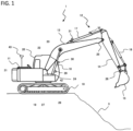
- the front work implement 12 includes a boom 13 angularly movably mounted on the upper swing structure 11, an arm 14 angularly movably mounted on a distal end of the boom 13, and a bucket (attachment) 15 angularly movably mounted on a distal end of the arm 14.
- the front work implement 12 also includes, as actuators for actuating the front work implement 12, a boom cylinder 16 that is a hydraulic cylinder for actuating the boom 13, an arm cylinder 17 that is a hydraulic cylinder for actuating the arm 14, and a bucket cylinder 18 that is a hydraulic cylinder for actuating the bucket 15.
- the boom angle sensor 24, the arm angle sensor 25, the bucket angle sensor 26, the inclination angle sensor 28, and the swinging angular velocity sensor 27 may be replaced with other sensors insofar as they can sense physical quantities from which posture information of the front work implement 12 can be calculated.
- the boom angle sensor 24, the arm angle sensor 25, and the bucket angle sensor 26 may be replaced with inclination angle sensors or inertia measurement units (IMUs).
- the boom bottom pressure sensor 29, the boom rod pressure sensor 30, the arm bottom pressure sensor 31, and the arm rod pressure sensor 32 may be replaced with other sensors insofar as they can sense physical quantities from which thrust forces produced by the boom cylinder 16 and the arm cylinder 17, i.e., drive force information of the front work implement 12, and load information of the cylinders 16 and 17 can be sensed).
- operation speeds of the boom cylinder 16 and the arm cylinder 17 may be sensed by stroke sensors, and operation speeds of the boom 13 and the arm 14 may be sensed by IMUs for sensing operation of the front work implement 12.
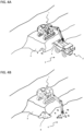
- the control lever 22a indicates raising and lowering of the boom 13 (extending and contracting of the boom cylinder 16) and dumping and crowding of the bucket 15 (extending and contracting of the bucket cylinder 18) whereas the control lever 22b indicates dumping and crowding of the arm 14 (extending and contracting of the arm cylinder 17) and leftward turning and rightward turning of the upper swing structure 11 (leftward rotation and rightward rotation of the hydraulic motor 19).
- the control lever 22a and the control lever 22b are dual composite multifunction control levers. Forward and rearward actions of the control lever 22a correspond respectively to raising and lowering of the boom 13, and leftward and rightward actions of the control lever 22a correspond respectively to dumping and crowding of the bucket 15.
- FIG. 2 is a schematic diagram of a hydraulic circuit of the hydraulic excavator 1 according to the present embodiment.
- the boom cylinder 16, the arm cylinder 17, the bucket cylinder 18, and the turn motor 19 are driven by a hydraulic working fluid delivered from a main pump 39.
- the rates at which and the directions in which the hydraulic working fluid flows as it is supplied to the hydraulic actuators 16 through 19 are controlled by respective control valves 35, 36, 37, and 38 that are actuated by drive signals that are output from the controller 21 according to the operation directions in which and the operation amounts by which the control levers 22a and 22b are operated.
- the control levers 22a and 22b generate control signals according to the operation directions in which and the operation amounts by which they are operated and outputs the generated control signals to the controller 21.
- the controller 21 generates drive signals (electric signals) according to the control signals, and outputs the generated drive signals to the control valves 35 through 38, which are electromagnetic proportional valves, thereby actuating the control valves 35 through 38.
- the degrees of opening of the control valves 35 through 38 vary according to the operation amounts by which the control levers 22a and 22b are operated. Specifically, the operation amounts by which the control levers 22a and 22b are operated define the speeds at which the hydraulic actuators 16 through 19 are operated. For example, when the operation amounts by which the control levers 22a and 22b are operated in a certain direction are increased, the degrees of opening of the control valves 35 through 38 in the corresponding direction are increased, increasing the rates at which the hydraulic working fluid flows as it is supplied to the hydraulic actuators 16 through 19 thereby to increase the speeds at which the hydraulic actuators 16 through 19 are operated. Consequently, the control signals generated by the control levers 22a and 22b have an aspect as speed commands for the hydraulic actuators 16 through 19. For this reason, the control signals generated by the control levers 22a and 22b may be herein referred to as speed commands for the hydraulic actuators 16 through 19 (the control valves 35 through 38).
- the controller 21 is supplied with signals input from the boom angle sensor 24, the arm angle sensor 25, the bucket angle sensor 26, the swinging angular velocity sensor 27, the inclination angle sensor 28, the boom bottom pressure sensor 29 and the boom rod pressure sensor 30 that are attached to the boom cylinder 16, and the arm bottom pressure sensor 31 and the arm rod pressure sensor 32 that are attached to the arm cylinder 17.
- the controller 21 calculates the load value of carried stuff (a carried load) carried by the front work implement 1 on the basis of these sensor signals, and displays the load measurement result on the monitor 23.
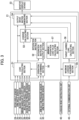
- FIG. 3 illustrates in the controller 21 the functions of the controller 21 as blocks.
- the controller 21 includes an operation determining section 50, a load calculating section 51, an integration instruction output section 52, a loadage calculating section 53, an output information generating section 54, a maximum loadage acquiring section 55, a target carried load calculating section 56, and a minimum integration load value calculating section 57.
- the target carried load calculating section 56 calculates a target carried load on the basis of remaining loadage that is obtained by subtracting the loadage calculated by the loadage calculating section 53 from the maximum loadage acquired by the maximum loadage acquiring section 55 and a remaining loading cycle count that is obtained by dividing the remaining loadage by a bucket volume.
- the integration instruction output section 52 outputs an integration instruction to the loadage calculating section 53 when the operation determining section 50 determines that the front work implement 12 has performed a transporting operation on the transportation machine 2 and when a carried load calculated by the load calculating section 51 is equal to or larger than a minimum integration load value calculated by the minimum integration load value calculating section 57.
- these two prerequisites represent the predetermined conditions under which the integration instruction output section 52 outputs an integration instruction.
- the output information generating section 54 produces information to be displayed on the monitor 23 on the basis of the outputs from the load calculating section 51, the loadage calculating section 53, the maximum loadage acquiring section 55, and the target carried load calculating section 56.
- the monitor 23 displays the information produced by the output information generating section 54.
- the equilibrium expressed by the equations (2) through (6) is modified and developed with respect to the weight Ml of the carried stuff.
- the load calculated according to the equations (1) through (7) cannot be of a constant value during the carrying operation due to sensor noises and hydraulic circuit characteristics. Therefore, weights Ml of the carried stuff that have been calculated during a predetermined period in the carrying operation are averaged to finalize a load.
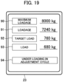
- the output information generating section 54 displays maximum loadage 90 of the transportation machine 2 acquired in step S113 and input from maximum loadage acquiring section 55, loadage 91 of the transportation machine 2 calculated in step S129 and input from the loadage calculating section 53, target carried load 92 calculated in step S117 or S118 and input from the target carried load calculating section 56, and carried load 93 calculated in step S126 and input from the load calculating section 51, as numerical values on the monitor 23.
- the hydraulic excavator 1 completes an excavating and loading work on the transportation machine 2 as a loading target in four cycles (in four loading cycles).
- the remaining loadage Mrem is larger than the minimum integrated value changing threshold value, and the target carriage load Mtar in each cycle exceeds the minimum integrated value changing threshold value (the middle portion of FIG. 9 ). Therefore, the minimum integration load value calculating section 57 keeps the minimum integrated value changing threshold value as the first set value (the lower portion of FIG. 9 ).
- the hydraulic excavator 1 adds the fact that a carried load exceeds a minimum integration load value as a condition for an integration, and the magnitude of the minimum integration load value is changed depending on the magnitude of the target carried load Mtar calculated each time the loadage Mt (the remaining loadage Mrem) is changed. Therefore, as an integration is carried out only when a carried load based on the progress of a loading work is measured, even if a carried load smaller than a carried load in a normal loading work is measured in an operation-analogous non-loading work, the measure carried load is excluded from an integration target.
- a minimum integration load value is not limited to the method described above, but a minimum integration load value may be calculated according to other methods. For example, a plurality of minimum integration load changing threshold values may be established, and a plurality of minimum integration load values may be established depending on the minimum integration load changing threshold values. Alternatively, a relationship between target carried loads and minimum integration load values may be determined in advance as a table or the like such that as a target carried load decreases, a minimum integration load value also decreases, and the minimum integration load value calculating section 57 may calculate a minimum integration load value depending on the magnitude of a target carried load according to the table.
- FIG. 11 is a schematic diagram illustrating the system configuration of a load measuring system that is incorporated in the work machine according to the present embodiment.
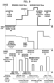
- FIG. 12 is a graph illustrating methods in which a hydraulic excavator according to the present embodiment changes the magnitude of a minimum integration load value that permits an integration of a carried load.
- FIG. 12A it is assumed that carried stuff a of the same type is to be loaded on a transportation machine A and a transportation machine B that have different maximum loadage, and a case in which the minimum integration load value calculating section 57 calculates a minimum integration load value on the basis of the maximum loadage of the transportation machines will be described below.
- the minimum integration load value calculating section 57 calculates a minimum integration load value on the basis of the maximum loadage of the transportation machines.
- FIG. 12B it is assumed that carried stuff a and b of different densities is to be loaded on transportation machines B that have the same maximum loadage, and a case in which the minimum integration load value calculating section 57 calculates a minimum integration load value on the basis of the types of the carried stuff will be described below.
- a minimum integration load value determined in step S121 illustrated in FIG. 8 is calculated depending on the bucket volume Mbk for the carried stuff a.
- the bucket volume Mbk is smaller than with the carried stuff a.
- the minimum integration load value calculating section 57 calculates a minimum integration load value on the basis of the type of the carried stuff (the density, the viscosity, or the like), thus the minimum integration load value can be optimized in loading works for loading carried stuff of different types, resulting in the same advantages as those according to the first embodiment.
- a work machine according to a third embodiment of the present invention will be described below with reference to FIGS. 13 and 14 .
- loading cycles on a transportation machine are counted, and a minimum integration load value is changed depending on a target carried load value and a loading cycle count.
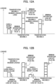
- FIG. 13 is a schematic diagram illustrating the system configuration of a load measuring system that is incorporated in the work machine according to the present embodiment.
- a controller 21 illustrated in FIG. 13 includes a loading cycle counting section 62 for measuring a loading cycle count that represents the number of times that the integration instruction output section 52 outputs an integration instruction.
- the minimum integration load value calculating section 57 is arranged to change the magnitude of a minimum integration load at the time the integration instruction output section 52 determines an integration instruction, on the basis of the outputs from the target carried load calculating section 56 and the loading cycle counting section 62.
- the minimum integration load value calculating section 57 calculates a first set value as a minimum integration load value when the magnitude of a target carried load is equal to or larger than a minimum integration load changing threshold value, and calculates as a minimum integration load value a second set value smaller than the first set value when the magnitude of a target carried load is smaller than the minimum integration load changing threshold value or when the loading cycle count from the loading cycle counting section 62 is equal to or larger than a predetermined threshold value (referred to as "loading cycle count threshold value").
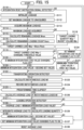
- step S132 the minimum integration load value calculating section 57 determines whether the target carried load Mtar is smaller than the minimum integration load changing threshold value or the loading cycle count is larger than the loading cycle count threshold value determined in advance in the minimum integration load value calculating section 57. If either one of these two conditions is satisfied, then control goes to step S120 in which the minimum integration load value is set to the second set value. Otherwise, control goes to step S121 in which the minimum integration load value is set to the first set value.
- the loading cycle count threshold value may be set to an integer that is 1 smaller the minimum number of loading cycles required for the hydraulic excavator 1 to load the transportation machine 2. For example, if the loading work is finished in four loading cycles, for example, then loading cycle count threshold value is set to 3.
- a load measuring system has a basic arrangement that is the same as the load measuring system illustrated in FIG. 3 , but is characterized in that when an integration instruction is output from the integration instruction output section 52 after the minimum integration load value calculating section 57 has calculated a second set value as the minimum integration load value, the minimum integration load value calculating section 57 calculates a first set value as the minimum integration load value regardless of the magnitude of the target carried load.
- the minimum integration load value calculating section 57 determines whether the minimum integration load value is the second set value or not in step S136 after step S129. If the minimum integration load value is the second set value, then the minimum integration load value changing flag is set to ON in step S137, after which control goes to step S130. If the minimum integration load value is not the second set value, then control goes to step S130 without changing the minimum integration load value changing flag.
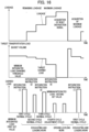
- FIG. 16 is a graph illustrating an example of changes in loadage Mt, a target carried load Mtar, a carried load, and a minimum integration load value according to the present embodiment.
- the loadage reset instruction unit 42 is operated, thereby outputting a reset instruction signal.
- step S119 Even if the target carried load is equal to or larger than the minimum integration load changing threshold value in step S119, control goes from step S119 to step S134 and the minimum integration load value is changed to the first set value. Therefore, the result remains the same. In other words, the minimum integration load value is necessarily set to the first set value regardless of the magnitude of the target carried value. Consequently, as illustrated in the lower portion of FIG. 16 , even if a carried load is measured in a ground level work performed before the loadage reset instruction unit 42 is operated after the fourth cycle has been finished, the carried load is not integrated as it is less than the first set value.
- step S110 a target carried load equal to or larger than the minimum integration load changing threshold value is calculated (the middle portion of FIG. 16 ), after which control goes from step S119 to step S134 in which the minimum integration load value changing flag is changed from ON back to OFF.
- a work machine according to a fifth embodiment of the present invention will be described below with reference to FIGS. 17 through 19 .
- the present embodiment is characterized in that a work status of the front work implement 12 is determined on the basis of a minimum carried load value and an integration instruction, and the work status is output to an indicating device such as the monitor 23 or the like, which notifies the operator, administrator, or the like of the work status.
- FIG. 17 is a schematic diagram illustrating the system configuration of a load measuring system that is incorporated in the work machine according to the present embodiment.
- a controller 21 illustrated in FIG. 17 includes a work status determining section 64 for determining a work status of the front work implement 12 on the basis of whether a second set value has been calculated by the minimum integration load value calculating section 57 or not and whether an integration instruction has been output from the integration instruction output section 52 or not.
- the work status determining section 64 determines a work status on the basis of the outputs from the loadage reset instruction unit 42, the operation determining section 50, the integration instruction output section 52, the loadage calculating section 53, and the minimum integration load value calculating section 57, and outputs the determined work status to the output information generating section 54 and the external communication unit 43.
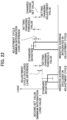
- FIG. 18 is a flowchart of a process that the controller 21 according to the present embodiment performs in the work status determining section 64. Each of the steps illustrated in FIG. 18 is executed in every predetermined sampling period by the controller 21. A case in which the work status determining section 64 outputs the determined work status to the output information generating section 54 (to the monitor 23) will be described hereinafter.
- the determined result from the work status determining section 64 may be output via the external communication unit 43 to a terminal such as an external computer or the like, so that the determined result IS appropriately referred to.
- the work status determining section 64 initializes the work status in step S140. Specifically, the work status is set to "PRIOR TO LOADING" indicating a status before carried stuff is loaded on the transportation machine 2 as a loading target (i.e., indicating that a loading operation in the first cycle has not been performed and loadage of the transportation machine 2 is zero), and held in a storage device in the controller 21.
- the work status determining section 64 outputs the work status that is held in the storage device to the monitor 23.
- FIG. 19 is a view illustrating an output screen of the monitor 23 according to the present embodiment.
- the output screen of the monitor 23 includes a work status display area 94.
- the work status display area 94 displays a message "PRIOR TO LOADING WORK.”
- the work status display area 94 displays a message in case the work status represents "UNDER ADJUSTMENT" (in step S154).
- step S142 the work status determining section 64 monitors whether an integration reset instruction signal has been output from the loadage reset instruction unit 42 or not. If it is determined that an integration reset instruction signal has been output, then control goes to step S143 in which the work status is set to "PRIOR TO LOADING" and held in the controller 21, after which control returns to step S141. In this case, the work status of "PRIOR TO LOADING" is displayed on the monitor 23 in step S141.
- step S142 If it is determined that an integration reset instruction signal has not been output in step S142, then the work status determining section 64 monitors whether a loading operation determination has been input from the operation determining section 50 or not. If it is determined that a loading operation determination has not been input, then control goes back to step S141 in which the work status held at this time is output to the monitor 23.
- step S144 if it is determined that a loading operation determination has been input in step S144 (i.e., if step S128 is executed in the flowchart illustrated in FIG. 8 ), then the work status determining section 64 waits in step S145 until the execution of step S120 or S121 in the flowchart illustrated in FIG. 8 is completed, after which control goes to step S146.
- step S145 the execution of step S120 or S121 in the flowchart illustrated in FIG. 8 is completed, after which control goes to step S146.
- step S148 the work status determining section 64 determines whether the minimum integration load value calculating section 57 has changed the minimum integration load value from the first set value to the second set value or not. If the minimum integration load value has been changed (i.e., has changed to the second set value) then control goes to step S152. If the minimum integration load value has not been changed (i.e., has remained to be the first set value) then control goes to step S149.
- the work status determining section 64 determines whether the carried load is larger than the second set value (the minimum carried load value) or not, thereby determining whether an integration instruction has been output from the integration instruction output section 52 or not, in step S152. If it is determined that an integration instruction has not been output, the work status determining section 64 sets in step S153 the work status to "GROUND LEVELING UNDER ADJUSTMENT" indicating that though an operation-analogous non-loading work is carried out in the adjustment cycle of the loading work, the carried load is not integrated, and holds the set work status in the controller 21, after which control goes back to step S141. In this case, a message indicating that the work status represents ground leveling under adjustment (“GROUND LEVELING IN ADJUSTMENT CYCLE,” for example) is displayed on the monitor 23 in step S141.
- step S154 the work status determining section 64 sets the work status to "UNDER ADJUSTMENT" indicating that a loading operation is carried out in the adjustment cycle of the loading work, and holds the set work status in the controller 21, after which control goes back to step S141.
- a message indicating that the work status represents under adjustment (“UNDER LOADING IN ADJUSTMENT CYCLE,” for example) is displayed on the monitor 23 in step S141.
- a work machine according to a sixth embodiment of the present invention will be described below with reference to FIGS. 20 through 22 .
- the present embodiment is characterized in that the second set value is changed on the basis of a variation of the carried load calculated after the second set value has been calculated by the minimum integration load value calculating section 57.
- step S163 the carried load storage section 65 calculates and holds an average and standard deviation of the carried load integrated in the adjustment cycle as indicated by the right bar in FIG. 22 . Then, the carried load storage section 65 calculates an adjustment cycle minimum integrated load difference that represents the difference between the standard deviation of the integrated carried load with respect to the average of the integrated carried load and the second set value (the minimum integration load value), after which control goes to step S165.
- step S164 the carried load storage section 65 calculates and holds an average and standard deviation of the carried load excluded from an integration in the adjustment cycle as indicated by the left bar in FIG. 22 . Then, the carried load storage section 65 calculates an adjustment cycle excluded load difference that represents the difference between the standard deviation of the carried load excluded from the integration with respect to the average of the carried load excluded from the integration and the second set value (the minimum integration load value), after which control goes to step S165.
- the load integrating condition changing section 66 adds a predetermined adjustment value set in the load integrating condition changing section 66 (hereinafter referred to as "setting changing adjustment value") to the second set value in step S167, after which control goes to step S168.
- setting changing adjustment value a predetermined adjustment value set in the load integrating condition changing section 66
- the transportation machine 2 may be judged as being loaded despite the fact that no loading is performed on the transportation machine 2, possibly giving rise to a cycle in which to integrate the carried load.
- such a cycle in which to integrate the carried load in error can be eliminated by increasing the second set value by adding the setting changing adjustment value thereto.
- step S168 the load integrating condition changing section 66 determines whether the adjustment cycle minimum integrated load difference in step S163 is smaller than the setting changing threshold value set in the load integrating condition changing section 66 or not. If the adjustment cycle minimum integrated load difference is larger than the setting changing threshold value, then control goes back to step S160.
- the target to be changed according to the present embodiment is not limited to the minimum integration load value in the adjustment cycle, i.e., the second set value. Rather, according to a method similar to the method described with reference to FIGS. 20 through 22 , the first set value as the minimum integration load value in the normal cycles or the minimum integration load changing threshold value as a trigger for changing the minimum integration load value from the first set value to the second set value may obviously be used as the target to be changed.
- the way in which the operation determining section 50 determines operations is not limited to the above method using the arm cylinder bottom pressure and the bucket angle. If the work machine is a lifting magnet machine, for example, then it is easy to determine a carrying operation and a loading operation on the basis of ON/OFF signals for magnet attraction.
- control lines and information lines that are understood as being required for the description of the embodiments. However, not all control lines and information lines of products are necessarily illustrated. Actually, almost all of the components may be considered as being connected to each other.
Landscapes
- Engineering & Computer Science (AREA)
- Mining & Mineral Resources (AREA)
- Civil Engineering (AREA)
- General Engineering & Computer Science (AREA)
- Structural Engineering (AREA)
- Physics & Mathematics (AREA)
- General Physics & Mathematics (AREA)
- Mechanical Engineering (AREA)
- Operation Control Of Excavators (AREA)
- Component Parts Of Construction Machinery (AREA)
Applications Claiming Priority (2)
| Application Number | Priority Date | Filing Date | Title |
|---|---|---|---|
| JP2018048648A JP6782271B2 (ja) | 2018-03-15 | 2018-03-15 | 作業機械 |
| PCT/JP2019/010944 WO2019177162A1 (ja) | 2018-03-15 | 2019-03-15 | 作業機械 |
Publications (3)
| Publication Number | Publication Date |
|---|---|
| EP3767039A1 EP3767039A1 (en) | 2021-01-20 |
| EP3767039A4 EP3767039A4 (en) | 2021-12-08 |
| EP3767039B1 true EP3767039B1 (en) | 2024-07-03 |
Family
ID=67907234
Family Applications (1)
| Application Number | Title | Priority Date | Filing Date |
|---|---|---|---|
| EP19767563.0A Active EP3767039B1 (en) | 2018-03-15 | 2019-03-15 | Working machine |
Country Status (6)
| Country | Link |
|---|---|
| US (1) | US11306460B2 (enExample) |
| EP (1) | EP3767039B1 (enExample) |
| JP (1) | JP6782271B2 (enExample) |
| KR (1) | KR102402515B1 (enExample) |
| CN (1) | CN111094661B (enExample) |
| WO (1) | WO2019177162A1 (enExample) |
Families Citing this family (12)
| Publication number | Priority date | Publication date | Assignee | Title |
|---|---|---|---|---|
| JP7088691B2 (ja) * | 2018-02-28 | 2022-06-21 | 株式会社小松製作所 | 積込機械の制御装置、制御方法および遠隔操作システム |
| US11041291B2 (en) * | 2018-09-14 | 2021-06-22 | Deere & Company | Controlling a work machine based on sensed variables |
| JP7173898B2 (ja) * | 2019-02-28 | 2022-11-16 | 日立建機株式会社 | 作業機械 |
| US11697917B2 (en) * | 2019-07-26 | 2023-07-11 | Deere & Company | Anticipatory modification of machine settings based on predicted operational state transition |
| JP7268577B2 (ja) * | 2019-10-31 | 2023-05-08 | コベルコ建機株式会社 | 作業機械 |
| JP7455568B2 (ja) | 2019-12-16 | 2024-03-26 | 株式会社小松製作所 | 作業機械、計測方法およびシステム |
| JP7287320B2 (ja) * | 2020-03-19 | 2023-06-06 | コベルコ建機株式会社 | 作業機械 |
| JP2021156078A (ja) * | 2020-03-30 | 2021-10-07 | 住友重機械工業株式会社 | ショベル |
| JP7452342B2 (ja) * | 2020-09-14 | 2024-03-19 | コベルコ建機株式会社 | 情報提示装置及び作業機械 |
| CN112255958A (zh) * | 2020-10-30 | 2021-01-22 | 广州市城市建设工程监理公司 | 一种自动化挖掘运输系统 |
| JPWO2022210897A1 (enExample) * | 2021-03-31 | 2022-10-06 | ||
| JP2025134217A (ja) * | 2024-03-04 | 2025-09-17 | 株式会社小松製作所 | 作業機械を含むシステム、作業機械、および作業機械の自動制御方法 |
Family Cites Families (17)
| Publication number | Priority date | Publication date | Assignee | Title |
|---|---|---|---|---|
| JPS58162816A (ja) * | 1982-03-23 | 1983-09-27 | Caterpillar Mitsubishi Ltd | 荷役積載重量監視装置 |
| KR910002234B1 (ko) * | 1982-12-01 | 1991-04-08 | 히다찌 겡끼 가부시기가이샤 | 적하 이송장치의 적하중량 표시장치 |
| JPS60141930A (ja) * | 1983-12-28 | 1985-07-27 | Hitachi Constr Mach Co Ltd | 油圧ショベルの積荷重量表示装置 |
| US4677579A (en) * | 1985-09-25 | 1987-06-30 | Becor Western Inc. | Suspended load measurement system |
| US5509293A (en) * | 1994-12-20 | 1996-04-23 | Caterpillar Inc. | Dynamic payload monitor |
| JP2925468B2 (ja) * | 1995-01-31 | 1999-07-28 | 株式会社小松製作所 | ダンプの積載重量監視装置 |
| JP2000129727A (ja) * | 1998-10-26 | 2000-05-09 | Hitachi Constr Mach Co Ltd | 建設機械の作業量計測装置 |
| US6931772B2 (en) * | 2001-10-18 | 2005-08-23 | Hitachi Construction Machinery Co., Ltd. | Hydraulic shovel work amount detection apparatus, work amount detection method, work amount detection result display apparatus |
| JP4017144B2 (ja) * | 2002-05-16 | 2007-12-05 | 株式会社小松製作所 | 土質改良装置 |
| JP4413122B2 (ja) * | 2004-10-13 | 2010-02-10 | 日立建機株式会社 | 油圧建設機械の制御装置 |
| US8340872B2 (en) | 2005-12-12 | 2012-12-25 | Caterpillar Inc. | Control system and method for capturing partial bucket loads in automated loading cycle |
| JP5138438B2 (ja) * | 2008-03-27 | 2013-02-06 | 株式会社小松製作所 | ホイールローダの積載荷重計測装置及び積載荷重計測方法 |
| JP2010089633A (ja) * | 2008-10-08 | 2010-04-22 | Caterpillar Japan Ltd | 作業量モニタリングシステム |
| US8909437B2 (en) * | 2012-10-17 | 2014-12-09 | Caterpillar Inc. | Payload Estimation system |
| JP5529241B2 (ja) | 2012-11-20 | 2014-06-25 | 株式会社小松製作所 | 作業機械および作業機械の作業量計測方法 |
| DE112014000134B4 (de) * | 2014-06-04 | 2016-09-22 | Komatsu Ltd. | Stellungsberechnungsvorrichtung für eine Arbeitsmaschine, Arbeitsmaschine und Stellungsberechnungsverfahren für eine Arbeitsmaschine |
| JP6604624B2 (ja) * | 2015-05-11 | 2019-11-13 | キャタピラー エス エー アール エル | 作業機械の自動振動装置 |
-
2018
- 2018-03-15 JP JP2018048648A patent/JP6782271B2/ja active Active
-
2019
- 2019-03-15 CN CN201980004316.9A patent/CN111094661B/zh active Active
- 2019-03-15 EP EP19767563.0A patent/EP3767039B1/en active Active
- 2019-03-15 KR KR1020207006305A patent/KR102402515B1/ko active Active
- 2019-03-15 WO PCT/JP2019/010944 patent/WO2019177162A1/ja not_active Ceased
- 2019-03-15 US US16/649,430 patent/US11306460B2/en active Active
Also Published As
| Publication number | Publication date |
|---|---|
| KR102402515B1 (ko) | 2022-05-30 |
| EP3767039A4 (en) | 2021-12-08 |
| US20200283992A1 (en) | 2020-09-10 |
| JP6782271B2 (ja) | 2020-11-11 |
| CN111094661B (zh) | 2022-06-14 |
| WO2019177162A1 (ja) | 2019-09-19 |
| EP3767039A1 (en) | 2021-01-20 |
| US11306460B2 (en) | 2022-04-19 |
| KR20200037350A (ko) | 2020-04-08 |
| CN111094661A (zh) | 2020-05-01 |
| JP2019158774A (ja) | 2019-09-19 |
Similar Documents
| Publication | Publication Date | Title |
|---|---|---|
| EP3767039B1 (en) | Working machine | |
| EP3763886B1 (en) | Work machinery | |
| CN110392756B (zh) | 作业机械 | |
| US11427984B2 (en) | Work machine | |
| KR102234963B1 (ko) | 유압 셔블 | |
| KR102562017B1 (ko) | 작업 기계 | |
| JP2018145754A (ja) | 作業機械の荷重計測装置 | |
| EP4101997B1 (en) | Work machine | |
| JP2025074594A (ja) | 作業機械および作業機械の制御方法 |
Legal Events
| Date | Code | Title | Description |
|---|---|---|---|
| STAA | Information on the status of an ep patent application or granted ep patent |
Free format text: STATUS: THE INTERNATIONAL PUBLICATION HAS BEEN MADE |
|
| PUAI | Public reference made under article 153(3) epc to a published international application that has entered the european phase |
Free format text: ORIGINAL CODE: 0009012 |
|
| STAA | Information on the status of an ep patent application or granted ep patent |
Free format text: STATUS: REQUEST FOR EXAMINATION WAS MADE |
|
| 17P | Request for examination filed |
Effective date: 20201015 |
|
| AK | Designated contracting states |
Kind code of ref document: A1 Designated state(s): AL AT BE BG CH CY CZ DE DK EE ES FI FR GB GR HR HU IE IS IT LI LT LU LV MC MK MT NL NO PL PT RO RS SE SI SK SM TR |
|
| AX | Request for extension of the european patent |
Extension state: BA ME |
|
| DAV | Request for validation of the european patent (deleted) | ||
| DAX | Request for extension of the european patent (deleted) | ||
| A4 | Supplementary search report drawn up and despatched |
Effective date: 20211109 |
|
| RIC1 | Information provided on ipc code assigned before grant |
Ipc: G01G 19/10 20060101ALI20211103BHEP Ipc: E02F 9/20 20060101AFI20211103BHEP |
|
| GRAP | Despatch of communication of intention to grant a patent |
Free format text: ORIGINAL CODE: EPIDOSNIGR1 |
|
| STAA | Information on the status of an ep patent application or granted ep patent |
Free format text: STATUS: GRANT OF PATENT IS INTENDED |
|
| INTG | Intention to grant announced |
Effective date: 20240125 |
|
| GRAS | Grant fee paid |
Free format text: ORIGINAL CODE: EPIDOSNIGR3 |
|
| GRAA | (expected) grant |
Free format text: ORIGINAL CODE: 0009210 |
|
| STAA | Information on the status of an ep patent application or granted ep patent |
Free format text: STATUS: THE PATENT HAS BEEN GRANTED |
|
| AK | Designated contracting states |
Kind code of ref document: B1 Designated state(s): AL AT BE BG CH CY CZ DE DK EE ES FI FR GB GR HR HU IE IS IT LI LT LU LV MC MK MT NL NO PL PT RO RS SE SI SK SM TR |
|
| REG | Reference to a national code |
Ref country code: CH Ref legal event code: EP |
|
| REG | Reference to a national code |
Ref country code: DE Ref legal event code: R096 Ref document number: 602019054624 Country of ref document: DE |
|
| REG | Reference to a national code |
Ref country code: LT Ref legal event code: MG9D |
|
| REG | Reference to a national code |
Ref country code: NL Ref legal event code: MP Effective date: 20240703 |
|
| PG25 | Lapsed in a contracting state [announced via postgrant information from national office to epo] |
Ref country code: PT Free format text: LAPSE BECAUSE OF FAILURE TO SUBMIT A TRANSLATION OF THE DESCRIPTION OR TO PAY THE FEE WITHIN THE PRESCRIBED TIME-LIMIT Effective date: 20241104 |
|
| REG | Reference to a national code |
Ref country code: AT Ref legal event code: MK05 Ref document number: 1699920 Country of ref document: AT Kind code of ref document: T Effective date: 20240703 |
|
| PG25 | Lapsed in a contracting state [announced via postgrant information from national office to epo] |
Ref country code: NL Free format text: LAPSE BECAUSE OF FAILURE TO SUBMIT A TRANSLATION OF THE DESCRIPTION OR TO PAY THE FEE WITHIN THE PRESCRIBED TIME-LIMIT Effective date: 20240703 |
|
| PG25 | Lapsed in a contracting state [announced via postgrant information from national office to epo] |
Ref country code: PT Free format text: LAPSE BECAUSE OF FAILURE TO SUBMIT A TRANSLATION OF THE DESCRIPTION OR TO PAY THE FEE WITHIN THE PRESCRIBED TIME-LIMIT Effective date: 20241104 Ref country code: NL Free format text: LAPSE BECAUSE OF FAILURE TO SUBMIT A TRANSLATION OF THE DESCRIPTION OR TO PAY THE FEE WITHIN THE PRESCRIBED TIME-LIMIT Effective date: 20240703 |
|
| PG25 | Lapsed in a contracting state [announced via postgrant information from national office to epo] |
Ref country code: NO Free format text: LAPSE BECAUSE OF FAILURE TO SUBMIT A TRANSLATION OF THE DESCRIPTION OR TO PAY THE FEE WITHIN THE PRESCRIBED TIME-LIMIT Effective date: 20241003 |
|
| PG25 | Lapsed in a contracting state [announced via postgrant information from national office to epo] |
Ref country code: FI Free format text: LAPSE BECAUSE OF FAILURE TO SUBMIT A TRANSLATION OF THE DESCRIPTION OR TO PAY THE FEE WITHIN THE PRESCRIBED TIME-LIMIT Effective date: 20240703 Ref country code: GR Free format text: LAPSE BECAUSE OF FAILURE TO SUBMIT A TRANSLATION OF THE DESCRIPTION OR TO PAY THE FEE WITHIN THE PRESCRIBED TIME-LIMIT Effective date: 20241004 Ref country code: PL Free format text: LAPSE BECAUSE OF FAILURE TO SUBMIT A TRANSLATION OF THE DESCRIPTION OR TO PAY THE FEE WITHIN THE PRESCRIBED TIME-LIMIT Effective date: 20240703 |
|
| PG25 | Lapsed in a contracting state [announced via postgrant information from national office to epo] |
Ref country code: BG Free format text: LAPSE BECAUSE OF FAILURE TO SUBMIT A TRANSLATION OF THE DESCRIPTION OR TO PAY THE FEE WITHIN THE PRESCRIBED TIME-LIMIT Effective date: 20240703 |
|
| PG25 | Lapsed in a contracting state [announced via postgrant information from national office to epo] |
Ref country code: LV Free format text: LAPSE BECAUSE OF FAILURE TO SUBMIT A TRANSLATION OF THE DESCRIPTION OR TO PAY THE FEE WITHIN THE PRESCRIBED TIME-LIMIT Effective date: 20240703 |
|
| PG25 | Lapsed in a contracting state [announced via postgrant information from national office to epo] |
Ref country code: IS Free format text: LAPSE BECAUSE OF FAILURE TO SUBMIT A TRANSLATION OF THE DESCRIPTION OR TO PAY THE FEE WITHIN THE PRESCRIBED TIME-LIMIT Effective date: 20241103 Ref country code: AT Free format text: LAPSE BECAUSE OF FAILURE TO SUBMIT A TRANSLATION OF THE DESCRIPTION OR TO PAY THE FEE WITHIN THE PRESCRIBED TIME-LIMIT Effective date: 20240703 |
|
| PG25 | Lapsed in a contracting state [announced via postgrant information from national office to epo] |
Ref country code: CZ Free format text: LAPSE BECAUSE OF FAILURE TO SUBMIT A TRANSLATION OF THE DESCRIPTION OR TO PAY THE FEE WITHIN THE PRESCRIBED TIME-LIMIT Effective date: 20240703 Ref country code: HR Free format text: LAPSE BECAUSE OF FAILURE TO SUBMIT A TRANSLATION OF THE DESCRIPTION OR TO PAY THE FEE WITHIN THE PRESCRIBED TIME-LIMIT Effective date: 20240703 |
|
| PG25 | Lapsed in a contracting state [announced via postgrant information from national office to epo] |
Ref country code: RS Free format text: LAPSE BECAUSE OF FAILURE TO SUBMIT A TRANSLATION OF THE DESCRIPTION OR TO PAY THE FEE WITHIN THE PRESCRIBED TIME-LIMIT Effective date: 20241003 Ref country code: ES Free format text: LAPSE BECAUSE OF FAILURE TO SUBMIT A TRANSLATION OF THE DESCRIPTION OR TO PAY THE FEE WITHIN THE PRESCRIBED TIME-LIMIT Effective date: 20240703 |
|
| PG25 | Lapsed in a contracting state [announced via postgrant information from national office to epo] |
Ref country code: RS Free format text: LAPSE BECAUSE OF FAILURE TO SUBMIT A TRANSLATION OF THE DESCRIPTION OR TO PAY THE FEE WITHIN THE PRESCRIBED TIME-LIMIT Effective date: 20241003 Ref country code: PL Free format text: LAPSE BECAUSE OF FAILURE TO SUBMIT A TRANSLATION OF THE DESCRIPTION OR TO PAY THE FEE WITHIN THE PRESCRIBED TIME-LIMIT Effective date: 20240703 Ref country code: NO Free format text: LAPSE BECAUSE OF FAILURE TO SUBMIT A TRANSLATION OF THE DESCRIPTION OR TO PAY THE FEE WITHIN THE PRESCRIBED TIME-LIMIT Effective date: 20241003 Ref country code: LV Free format text: LAPSE BECAUSE OF FAILURE TO SUBMIT A TRANSLATION OF THE DESCRIPTION OR TO PAY THE FEE WITHIN THE PRESCRIBED TIME-LIMIT Effective date: 20240703 Ref country code: IS Free format text: LAPSE BECAUSE OF FAILURE TO SUBMIT A TRANSLATION OF THE DESCRIPTION OR TO PAY THE FEE WITHIN THE PRESCRIBED TIME-LIMIT Effective date: 20241103 Ref country code: HR Free format text: LAPSE BECAUSE OF FAILURE TO SUBMIT A TRANSLATION OF THE DESCRIPTION OR TO PAY THE FEE WITHIN THE PRESCRIBED TIME-LIMIT Effective date: 20240703 Ref country code: GR Free format text: LAPSE BECAUSE OF FAILURE TO SUBMIT A TRANSLATION OF THE DESCRIPTION OR TO PAY THE FEE WITHIN THE PRESCRIBED TIME-LIMIT Effective date: 20241004 Ref country code: FI Free format text: LAPSE BECAUSE OF FAILURE TO SUBMIT A TRANSLATION OF THE DESCRIPTION OR TO PAY THE FEE WITHIN THE PRESCRIBED TIME-LIMIT Effective date: 20240703 Ref country code: ES Free format text: LAPSE BECAUSE OF FAILURE TO SUBMIT A TRANSLATION OF THE DESCRIPTION OR TO PAY THE FEE WITHIN THE PRESCRIBED TIME-LIMIT Effective date: 20240703 Ref country code: CZ Free format text: LAPSE BECAUSE OF FAILURE TO SUBMIT A TRANSLATION OF THE DESCRIPTION OR TO PAY THE FEE WITHIN THE PRESCRIBED TIME-LIMIT Effective date: 20240703 Ref country code: BG Free format text: LAPSE BECAUSE OF FAILURE TO SUBMIT A TRANSLATION OF THE DESCRIPTION OR TO PAY THE FEE WITHIN THE PRESCRIBED TIME-LIMIT Effective date: 20240703 Ref country code: AT Free format text: LAPSE BECAUSE OF FAILURE TO SUBMIT A TRANSLATION OF THE DESCRIPTION OR TO PAY THE FEE WITHIN THE PRESCRIBED TIME-LIMIT Effective date: 20240703 |
|
| REG | Reference to a national code |
Ref country code: DE Ref legal event code: R097 Ref document number: 602019054624 Country of ref document: DE |
|
| PG25 | Lapsed in a contracting state [announced via postgrant information from national office to epo] |
Ref country code: DK Free format text: LAPSE BECAUSE OF FAILURE TO SUBMIT A TRANSLATION OF THE DESCRIPTION OR TO PAY THE FEE WITHIN THE PRESCRIBED TIME-LIMIT Effective date: 20240703 Ref country code: SM Free format text: LAPSE BECAUSE OF FAILURE TO SUBMIT A TRANSLATION OF THE DESCRIPTION OR TO PAY THE FEE WITHIN THE PRESCRIBED TIME-LIMIT Effective date: 20240703 Ref country code: RO Free format text: LAPSE BECAUSE OF FAILURE TO SUBMIT A TRANSLATION OF THE DESCRIPTION OR TO PAY THE FEE WITHIN THE PRESCRIBED TIME-LIMIT Effective date: 20240703 |
|
| PG25 | Lapsed in a contracting state [announced via postgrant information from national office to epo] |
Ref country code: EE Free format text: LAPSE BECAUSE OF FAILURE TO SUBMIT A TRANSLATION OF THE DESCRIPTION OR TO PAY THE FEE WITHIN THE PRESCRIBED TIME-LIMIT Effective date: 20240703 |
|
| PG25 | Lapsed in a contracting state [announced via postgrant information from national office to epo] |
Ref country code: SK Free format text: LAPSE BECAUSE OF FAILURE TO SUBMIT A TRANSLATION OF THE DESCRIPTION OR TO PAY THE FEE WITHIN THE PRESCRIBED TIME-LIMIT Effective date: 20240703 Ref country code: IT Free format text: LAPSE BECAUSE OF FAILURE TO SUBMIT A TRANSLATION OF THE DESCRIPTION OR TO PAY THE FEE WITHIN THE PRESCRIBED TIME-LIMIT Effective date: 20240703 |
|
| PLBE | No opposition filed within time limit |
Free format text: ORIGINAL CODE: 0009261 |
|
| STAA | Information on the status of an ep patent application or granted ep patent |
Free format text: STATUS: NO OPPOSITION FILED WITHIN TIME LIMIT |
|
| 26N | No opposition filed |
Effective date: 20250404 |
|
| PG25 | Lapsed in a contracting state [announced via postgrant information from national office to epo] |
Ref country code: SE Free format text: LAPSE BECAUSE OF FAILURE TO SUBMIT A TRANSLATION OF THE DESCRIPTION OR TO PAY THE FEE WITHIN THE PRESCRIBED TIME-LIMIT Effective date: 20240703 |
|
| PG25 | Lapsed in a contracting state [announced via postgrant information from national office to epo] |
Ref country code: MC Free format text: LAPSE BECAUSE OF FAILURE TO SUBMIT A TRANSLATION OF THE DESCRIPTION OR TO PAY THE FEE WITHIN THE PRESCRIBED TIME-LIMIT Effective date: 20240703 |
|
| REG | Reference to a national code |
Ref country code: CH Ref legal event code: H13 Free format text: ST27 STATUS EVENT CODE: U-0-0-H10-H13 (AS PROVIDED BY THE NATIONAL OFFICE) Effective date: 20251023 |
|
| PG25 | Lapsed in a contracting state [announced via postgrant information from national office to epo] |
Ref country code: LU Free format text: LAPSE BECAUSE OF NON-PAYMENT OF DUE FEES Effective date: 20250315 |
|
| REG | Reference to a national code |
Ref country code: BE Ref legal event code: MM Effective date: 20250331 |
|
| PG25 | Lapsed in a contracting state [announced via postgrant information from national office to epo] |
Ref country code: FR Free format text: LAPSE BECAUSE OF NON-PAYMENT OF DUE FEES Effective date: 20250331 |
|
| PG25 | Lapsed in a contracting state [announced via postgrant information from national office to epo] |
Ref country code: BE Free format text: LAPSE BECAUSE OF NON-PAYMENT OF DUE FEES Effective date: 20250331 |
|
| PG25 | Lapsed in a contracting state [announced via postgrant information from national office to epo] |
Ref country code: CH Free format text: LAPSE BECAUSE OF NON-PAYMENT OF DUE FEES Effective date: 20250331 |
|
| PG25 | Lapsed in a contracting state [announced via postgrant information from national office to epo] |
Ref country code: IE Free format text: LAPSE BECAUSE OF NON-PAYMENT OF DUE FEES Effective date: 20250315 |
|
| PGFP | Annual fee paid to national office [announced via postgrant information from national office to epo] |
Ref country code: GB Payment date: 20260202 Year of fee payment: 8 |
|
| PGFP | Annual fee paid to national office [announced via postgrant information from national office to epo] |
Ref country code: DE Payment date: 20260128 Year of fee payment: 8 |