EP3763882B1 - Schnellwechsler - Google Patents
Schnellwechsler Download PDFInfo
- Publication number
- EP3763882B1 EP3763882B1 EP20176499.0A EP20176499A EP3763882B1 EP 3763882 B1 EP3763882 B1 EP 3763882B1 EP 20176499 A EP20176499 A EP 20176499A EP 3763882 B1 EP3763882 B1 EP 3763882B1
- Authority
- EP
- European Patent Office
- Prior art keywords
- locking
- quick coupler
- carrier
- display device
- electrical
- Prior art date
- Legal status (The legal status is an assumption and is not a legal conclusion. Google has not performed a legal analysis and makes no representation as to the accuracy of the status listed.)
- Active
Links
Images


Classifications
-
- G—PHYSICS
- G08—SIGNALLING
- G08B—SIGNALLING SYSTEMS, e.g. PERSONAL CALLING SYSTEMS; ORDER TELEGRAPHS; ALARM SYSTEMS
- G08B5/00—Visible signalling systems, e.g. visible personal calling systems or remote indication of seats occupied
- G08B5/22—Visible signalling systems, e.g. visible personal calling systems or remote indication of seats occupied using electric transmission; using electromagnetic transmission
-
- E—FIXED CONSTRUCTIONS
- E02—HYDRAULIC ENGINEERING; FOUNDATIONS; SOIL SHIFTING
- E02F—DREDGING; SOIL-SHIFTING
- E02F3/00—Dredgers; Soil-shifting machines
- E02F3/04—Dredgers; Soil-shifting machines mechanically-driven
- E02F3/28—Dredgers; Soil-shifting machines mechanically-driven with digging tools mounted on a dipper- or bucket-arm, i.e. there is either one arm or a pair of arms, e.g. dippers, buckets
- E02F3/36—Component parts
- E02F3/3604—Devices to connect tools to arms, booms or the like
- E02F3/3609—Devices to connect tools to arms, booms or the like of the quick acting type, e.g. controlled from the operator seat
- E02F3/3627—Devices to connect tools to arms, booms or the like of the quick acting type, e.g. controlled from the operator seat with a hook and a longitudinal locking element
-
- B—PERFORMING OPERATIONS; TRANSPORTING
- B60—VEHICLES IN GENERAL
- B60Q—ARRANGEMENT OF SIGNALLING OR LIGHTING DEVICES, THE MOUNTING OR SUPPORTING THEREOF OR CIRCUITS THEREFOR, FOR VEHICLES IN GENERAL
- B60Q5/00—Arrangement or adaptation of acoustic signal devices
- B60Q5/005—Arrangement or adaptation of acoustic signal devices automatically actuated
-
- E—FIXED CONSTRUCTIONS
- E02—HYDRAULIC ENGINEERING; FOUNDATIONS; SOIL SHIFTING
- E02F—DREDGING; SOIL-SHIFTING
- E02F3/00—Dredgers; Soil-shifting machines
- E02F3/04—Dredgers; Soil-shifting machines mechanically-driven
- E02F3/28—Dredgers; Soil-shifting machines mechanically-driven with digging tools mounted on a dipper- or bucket-arm, i.e. there is either one arm or a pair of arms, e.g. dippers, buckets
- E02F3/36—Component parts
- E02F3/3604—Devices to connect tools to arms, booms or the like
- E02F3/3609—Devices to connect tools to arms, booms or the like of the quick acting type, e.g. controlled from the operator seat
- E02F3/3659—Devices to connect tools to arms, booms or the like of the quick acting type, e.g. controlled from the operator seat electrically-operated
-
- E—FIXED CONSTRUCTIONS
- E02—HYDRAULIC ENGINEERING; FOUNDATIONS; SOIL SHIFTING
- E02F—DREDGING; SOIL-SHIFTING
- E02F3/00—Dredgers; Soil-shifting machines
- E02F3/04—Dredgers; Soil-shifting machines mechanically-driven
- E02F3/28—Dredgers; Soil-shifting machines mechanically-driven with digging tools mounted on a dipper- or bucket-arm, i.e. there is either one arm or a pair of arms, e.g. dippers, buckets
- E02F3/36—Component parts
- E02F3/3604—Devices to connect tools to arms, booms or the like
- E02F3/3609—Devices to connect tools to arms, booms or the like of the quick acting type, e.g. controlled from the operator seat
- E02F3/3663—Devices to connect tools to arms, booms or the like of the quick acting type, e.g. controlled from the operator seat hydraulically-operated
-
- E—FIXED CONSTRUCTIONS
- E02—HYDRAULIC ENGINEERING; FOUNDATIONS; SOIL SHIFTING
- E02F—DREDGING; SOIL-SHIFTING
- E02F9/00—Component parts of dredgers or soil-shifting machines, not restricted to one of the kinds covered by groups E02F3/00 - E02F7/00
- E02F9/24—Safety devices, e.g. for preventing overload
-
- E—FIXED CONSTRUCTIONS
- E02—HYDRAULIC ENGINEERING; FOUNDATIONS; SOIL SHIFTING
- E02F—DREDGING; SOIL-SHIFTING
- E02F9/00—Component parts of dredgers or soil-shifting machines, not restricted to one of the kinds covered by groups E02F3/00 - E02F7/00
- E02F9/26—Indicating devices
-
- B—PERFORMING OPERATIONS; TRANSPORTING
- B60—VEHICLES IN GENERAL
- B60Q—ARRANGEMENT OF SIGNALLING OR LIGHTING DEVICES, THE MOUNTING OR SUPPORTING THEREOF OR CIRCUITS THEREFOR, FOR VEHICLES IN GENERAL
- B60Q9/00—Arrangement or adaptation of signal devices not provided for in one of main groups B60Q1/00 - B60Q7/00, e.g. haptic signalling
-
- E—FIXED CONSTRUCTIONS
- E02—HYDRAULIC ENGINEERING; FOUNDATIONS; SOIL SHIFTING
- E02F—DREDGING; SOIL-SHIFTING
- E02F3/00—Dredgers; Soil-shifting machines
- E02F3/04—Dredgers; Soil-shifting machines mechanically-driven
- E02F3/28—Dredgers; Soil-shifting machines mechanically-driven with digging tools mounted on a dipper- or bucket-arm, i.e. there is either one arm or a pair of arms, e.g. dippers, buckets
- E02F3/36—Component parts
- E02F3/3604—Devices to connect tools to arms, booms or the like
- E02F3/3609—Devices to connect tools to arms, booms or the like of the quick acting type, e.g. controlled from the operator seat
- E02F3/3622—Devices to connect tools to arms, booms or the like of the quick acting type, e.g. controlled from the operator seat with a hook and a locking element acting on a pin
-
- E—FIXED CONSTRUCTIONS
- E02—HYDRAULIC ENGINEERING; FOUNDATIONS; SOIL SHIFTING
- E02F—DREDGING; SOIL-SHIFTING
- E02F3/00—Dredgers; Soil-shifting machines
- E02F3/04—Dredgers; Soil-shifting machines mechanically-driven
- E02F3/96—Dredgers; Soil-shifting machines mechanically-driven with arrangements for alternate or simultaneous use of different digging elements
- E02F3/963—Arrangements on backhoes for alternate use of different tools
Definitions
- the invention relates to a quick coupler according to the preamble of claim 1.
- the invention also relates to the use of a display device for such a quick coupler.
- Such quick couplers are used to easily and conveniently change different attachments on construction machines.
- a quick coupler for example, swivel buckets, grippers, scissors, compactors, magnets, hydraulic hammers or other attachments can be coupled or uncoupled from a driver's cab, for example to the boom of an excavator, in just a few seconds and with a high level of safety.
- a generic quick coupler is known. This contains a carrier which has first receptacles on one side for holding a first coupling element provided on an attachment and, on the other side, second receptacles with a locking element movable between a release position and a locking position for releasably holding a second coupling element.
- a mechanical display device for checking the locking is also arranged on the carrier.
- a quick-change system which comprises first or second sensors for checking a correct locking position of locking elements or a correct positioning between retaining bolts and contact openings corresponding to the retaining bolts, the data recorded by the sensors being transferred to a driver's cab for an auditory, visual or tactile display the coupling state can be played.
- a display device arranged on the quick-change system can be replaced.
- the object of the invention is to create a quick coupler of the type mentioned at the beginning and a display device for use with such a quick coupler, which enable improved control of proper locking for a machine operator and people in the danger zone of the machine.
- the display device contains an electrical locking display and an electrical control device which activates the locking display in an extended locking position of the locking element and deactivates it in a retracted release position and an extended position of the locking element that deviates from the locking position. Correct locking is therefore only indicated if the second coupling element is also in its intended position for correct locking. To monitor and display proper locking, not only the position of the locking element but also the position of the second coupling element is taken into account. This can improve control and increase security.
- Activation of the electrical locking indicator means the output of a specific signal from the locking indicator. Deactivation means the non-output of this particular signal. If the specific signal is replaced by another signal, this also constitutes deactivation within the meaning of this document.
- the electrical control device can be a switch controlled by the movement of the locking element, which contains a first switching element associated with the locking element and a second switching element associated with the locking indicator/display device for controlling the locking indicator.
- the switch can advantageously be an electro-mechanical switch, which is designed, for example, in the form of a button.
- the button can be designed, for example, as a roller button or as a sliding button.
- a roller stylus is low-wear, but is more complex to manufacture than a sliding stylus.
- Roller feeler is a rotationally mounted feeler element designed, for example, as a rotatably mounted roller, which rolls on a control cam.
- a sliding switch is a non-rotatable element that slides or grinds on a control cam.
- exactly one switch is provided. Compared to a multi-switch system, a mono-switch system is simpler and more cost-effective. However, a design as a redundant system is also conceivable and possible.
- non-contact switches such as electrical and/or magnetic proximity switches or the like can also be used.
- the first switching element can contain at least one cam that interacts with the second switching element.
- Position or status information of the locking element can be encoded in a simple manner via the cam. This information can be recorded by the second switching element.
- the cam can be part of a control curve.
- a cam can be designed positively as an elevation or negatively as a depression of a control curve with a positive or negative height.
- the control cam can be easily adjusted with additional cams.
- the cam can in particular be designed as a rotary cam, as an axial cam or as a linear cam.
- a rotary cam the cam or control cam is attached to the circumference of a rotationally symmetrical part rotating about its axis of symmetry.
- an axial cam the cam or control cam is attached axially to the end face of a part rotating about an axis of rotation.
- a linear cam the cam or control cam is attached along a straight-line movable, e.g. rod-shaped part.
- a control cam may include multiple cams.
- the cams can have the same or different heights. This makes it possible to provide more information about a position and/or condition of the locking element.
- the second switching element can be mechanically connected to the locking element via a linkage, in particular a rigid linkage. This enables a simple and robust design of the display device.
- the electrical locking indicator preferably contains an optical and/or acoustic signal generator.
- Opto-electrical (short: optical) and acousto-electrical (short: acoustic) signal transmitters have the advantage of low reactance compared to mechanical display means and can be controlled and regulated in fractions of a second. This also enables complex signal patterns. For example, it is possible to adapt or change the rhythm of the signal delivery in addition to the signal height (wavelength or pitch). Visual and acoustic signaling devices can also be combined.
- An acoustic signaling system is, for example, a buzzer, a siren or a loudspeaker.
- Acoustic signaling systems offer the advantage that there does not have to be visual contact between the signal generator and the signal addressee.
- different positions or states of the locking element can be coded with different acoustic signals, so that, for example, a continuous, subtle buzzing tone sounds during the engagement process and a short confirmation tone sounds after the clutch has been engaged.
- the optical signal generator of the electrical locking indicator is advantageously designed as a lamp that emits, for example, diffuse or concentrated light.
- the light source can be designed, for example, as an LED or laser.
- Optical signal transmitters have the advantage that they can be set up to radiate in just one direction or in several directions. This has the advantage that other people in the danger zone of a construction machine can also be informed about the coupling states of a quick coupler.
- Light sources have the advantage of being visible even at night. Depending on the requirements, one or more lamps can be provided.
- a light source can be set up to light up in one or more colors.
- a light source can also be set up to light up at certain intervals.
- the electrical locking indicator and the electrical control device can be accommodated in a common housing. This means that the electrical components of the display device are better protected from the effects of the weather.
- the housing can be designed to be transparent or semi-transparent.
- signal transmitters designed as lighting means can be placed within the housing.
- a semi-transparent housing can then advantageously act as a light diffuser in such a way that semi-transparent parts of the housing shine when illuminated by a lamp. This allows large-area illuminated displays to be created, which increases visibility.
- a light display can light up in one or more colors.
- a light display can include several light sources that light up in one or more colors.
- the housing can also have reflective surfaces. This allows light signals to be amplified or bundled. Certain positions or states of the locking element and thus certain coupling states can be coded by choosing a certain color of the light display.
- a slow flashing of the signal generator in one color can indicate the release position of the locking element, while a rapid flashing in a different color can indicate a position of the locking element that deviates from the release position and the locking position.
- the display device can have a connection for connecting an external display.
- An external display can be, for example, a screen in a driver's cab of a construction machine.
- the connection option creates opportunities for creating redundant display devices.
- the invention also relates to the use of a display device for a quick coupler described above.
- the display device has the special features and features described above.
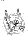
- a quick coupler 1 is shown for easily and conveniently changing different attachments on construction machines, in particular excavators.
- swivel buckets, grippers, scissors, magnets, compressors, hydraulic hammers or other mechanical or hydraulic attachments can be attached, for example via an in Figure 2
- Adapter 2 shown can be easily and conveniently coupled or uncoupled from a driver's cab to a boom or other attachment of an excavator or other construction vehicle.
- the adapter 2 which can be attached to an attachment, contains a base plate 3 and two mutually parallel side cheeks 4, between which a first bolt-shaped coupling element 5 and a second bolt-shaped coupling element 6 spaced therefrom at a predetermined distance for releasably connecting to the quick coupler 1 are arranged.
- the two bolt-shaped coupling elements 5 and 6 can be inserted into corresponding holes in the side walls 4 and fixed there.
- the bolt-shaped coupling elements 5 and 6 can also be arranged directly on the attachment.
- Quick coupler 1 shown in different perspectives contains a carrier 7 designed as a welded or cast part, which has first receptacles 8, which are open towards the front on one side, for receiving and holding the first bolt-shaped coupling element 5 and, on the other side, second receptacles 9 which are open downwards and have a locking element 10 for receiving and holding the second bolt-shaped coupling element 6.
- the quick coupler 1 contains two spaced-apart receptacles 8 for the first coupling element 5 on one side of the carrier 7 and two receptacles 9 for the second coupling element 6 on the other side.
- the first receptacles 8, which are open towards the front, are claw-shaped or designed fork-shaped.
- the second receptacles 9, which are open at the bottom, have a curved contact surface 11 for the contact of the second bolt-shaped coupling element 6.
- the carrier 9 contains on its top side two mutually parallel side parts 12, in which continuous openings 13 are provided for fastening bolts, not shown, for fastening the quick coupler 1 to a boom of an excavator or a connecting part of another construction vehicle.
- the quick coupler 1 also contains two locking elements 10 designed as locking bolts, which are located within the carrier 7 in Figure 1a shown guide holes 14 slidably guided and together by an in Figure 1b H-shaped cylinder 15 shown can be moved hydraulically between a retracted release position for releasing or coupling an attachment and an extended locking position V.
- the downwardly open second receptacles 9 are closed on the underside by the locking elements 10 arranged in the guide bores 14, so that the second bolt-shaped coupling element 6 is gripped under by the locking elements 10.
- Catch hooks 17 that can be pivoted about a transverse axis 16 are also arranged on the receptacles 8 for the first coupling element 5. These catch hooks 17 are from the Coupling elements 5 can be pivoted via a nose 18 between a downwardly pivoted coupling position and an upwardly pivoted closed position.
- the quick coupler 1 which is usually arranged on a boom of an excavator, is used in accordance with Figure 3A first moved in such a way that the first coupling element 5, which is arranged, for example, on the adapter 2 or on the attachment, is moved into the claw-shaped or fork-shaped receptacles 8 on one side of the quick coupler 1.
- the catch hooks 17 are also moved via the lugs 18 from the downwardly pivoted coupling position into the upwardly pivoted closed position.
- the locking elements 10 are in a release position L that is completely retracted into the carrier 7.
- the quick coupler 1 is pivoted around the first bolt-shaped coupling element 5 with the locking elements 10 still retracted so that the second coupling element 6 is attached to the adapter 2 or attachment according to Figure 3b comes to rest on the contact surfaces 11 of the downwardly open receptacles 9 on the other side of the quick coupler 1.
- the locking elements 10, which are displaceably arranged in the guide bores 14 in the carrier 7 of the quick coupler 1 can then be moved hydraulically into an in Figure 3b shown locking position V are extended, so that the second bolt-shaped coupling element 6 is gripped under by the two locking elements 10 on the quick coupler 1 and the attachment is thus held on the quick coupler 1.
- a faulty coupling process occurs, for example, if the locking elements 11 are extended before the coupling elements 5 are in their correct locking position, ie they hit the lower contact surface 11 of the carrier 7. This can be the case, for example, if the quick coupler 1 is not lowered properly due to incorrect operation or due to contamination between adapter 2 and quick coupler 1.
- the locking elements 10 extend, but without capturing the coupling elements 5 of the adapter 2 and bracing them relative to the carrier 7 of the quick coupler 1.
- the Locking elements 10 move as in Fig. 3c shown above the bolt-shaped coupling elements 5, so that there is no firm connection between adapter 2 and quick coupler 1.
- the display device 19 has an electrical control device 21 for checking a correct locking state or a correct position of the locking element 10, which is movable between a retracted release position, an extended locking position V and an unlocked extended position U that deviates from the locking position, and one connected to the control device 21 Electrical locking display 20 for displaying at least one correct locking position V with a first signal and for displaying an unlocked extended position U and / or retracted release position of the locking element 10 that deviates from the correct locking position V by a second signal.
- the second signal merely consists of deactivating the first signal.
- the electrical control device 21 is designed as a switch actuated by the movement of the locking element 10 with a first switching element 22 assigned to the locking element 10 and a second switching element 23 assigned to the locking indicator 20 for controlling the signal generator 21.
- the second switching element 23 is designed as a button that is actuated by the first switching element 22 and can be moved in one axis.
- the button is designed as a roller button.
- the first switching element 22 is designed as a cam slide (linear cam) with a cam 24 that interacts with the second switching element 23.
- the electrical control device 21 can also be designed as a non-contact switch, such as an inductive proximity sensor or the like.
- the cam slide has a control cam with exactly one cam 24, the cam or the position of the cam encoding a correct locking position V of the locking element 10.
- the cam here is designed as a sinusoidal elevation with a certain height.
- the first switching element 22, designed here as a cam slide with the cam 24, has an in Figure 2 shown, rigid linkage 25 and a holder 26 connected to the cylinder 15 used to move the locking elements 10. By displacing the locking elements 10 via the cylinder 15 into the Figures 3a to 3c In the positions shown, the first switching element 22, designed as a cam slide with the cam 24, is also moved into the position via the linkage 25 Figures 4a to 4c positions shown moved.
- the electrical control device 21 is designed in such a way that the electrical locking indicator 20 comprising signal generators is only activated when the locking elements 10 are in the in Figure 3b locking position V shown.
- the signal generators of the electrical locking indicator 20, which are controlled by the electrical control device 21, are designed as optical signal generators 27 with two lamps designed here as light-emitting diodes. Using two separate light sources, the visibility of the light display can be improved.
- the electrical locking indicator can also have acoustic signaling devices, for example a loudspeaker.
- the locking indicator 20 is activated in the form of the lamps, ie the control device 21 here closes a circuit in the form of the second switching element 22 for operating the lamps.
- the second switching element acts here as an analog switch or is connected to one, so that the second switching element 23 deflected by the cam 24 directly controls the electrical locking indicator.
- an electrical processing device could also be connected upstream or downstream of the second switching element 23 for indirectly closing the circuit.
- the circuit can be a circuit belonging to the on-board electrical system of the construction machine.
- the electrical display device 19 it is also conceivable and possible for the electrical display device 19 to be supplied independently, for example by a rechargeable battery element. This could be mounted inside the housing 28, for example.
- the cam slider has a plurality of cams 24 with different heights, which encode different positions or states of the locking elements 10.
- the electrical locking indicator 20 and the electrical control device 21 are housed in a common housing 28.
- the housing which is designed here in a square shape, is transparent on its top with a transparent cover plate.
- the housing could have transparent elements on other sides or could also be made completely transparent.
- Other housing shapes not shown in the exemplary embodiment are possible, in particular round, semicircular or dome-shaped housing shapes. The shape can advantageously improve visibility on several sides.
- the housing can also be partially or completely semi-transparent. This reduces glare and increases the illuminated area.
- a connection 29 for connection to external displays or the like is attached to the housing 28. Signals from the display device can be picked up via the connection and, for example, forwarded for output on an external screen located in the driver's cab of a construction machine.
Landscapes
- Engineering & Computer Science (AREA)
- Mechanical Engineering (AREA)
- General Engineering & Computer Science (AREA)
- Mining & Mineral Resources (AREA)
- Civil Engineering (AREA)
- Structural Engineering (AREA)
- Physics & Mathematics (AREA)
- General Physics & Mathematics (AREA)
- Electromagnetism (AREA)
- Acoustics & Sound (AREA)
- Component Parts Of Construction Machinery (AREA)
- Quick-Acting Or Multi-Walled Pipe Joints (AREA)
- Shovels (AREA)
- Human Computer Interaction (AREA)
Description
- Die Erfindung betrifft einen Schnellwechsler nach dem Oberbegriff des Anspruchs 1. Die Erfindung betrifft außerdem die Verwendung einer Anzeigevorrichtung für einen derartigen Schnellwechsler.
- Solche Schnellwechsler werden zum einfachen und bequemen Wechseln von unterschiedlichen Anbaugeräten an Baumaschinen eingesetzt. Mit einem derartigen Schnellwechsler können z.B. Schwenklöffel, Greifer, Scheren, Verdichter, Magnete, Hydraulikhammer oder andere Anbaugeräte in wenigen Sekunden und mit hohem Sicherheitsstandard von einer Fahrerkabine aus z.B. an einem Ausleger eines Baggers an- bzw. abgekuppelt werden.
- Aus der
DE 10 2015 009 491 A1 ist ein gattungsgemäßer Schnellwechsler bekannt. Dieser enthält einen Träger, der an einer Seite erste Aufnahmen zur Halterung eines an einem Anbaugerät vorgesehenen ersten Kopplungselements und an der anderen Seite zweite Aufnahmen mit einem zwischen einer Lösestellung und einer Verriegelungsstellung bewegbaren Verriegelungselement zur lösbaren Halterung eines zweiten Kopplungselements aufweist. An dem Träger ist außerdem eine mechanische Anzeigevorrichtung zur Kontrolle der Verriegelung angeordnet. - Ferner ist aus der
WO 2014 058 380 A1 ein Schnellwechselsystem bekannt, das erste bzw. zweite Sensoren zur Überprüfung einer korrekten Verschlussposition von Verschlusselementen bzw. eine korrekte Positionierung zwischen Haltebolzen und zu den Haltebolzen korrespondierenden Anlageöffnungen umfasst, wobei die von den Sensoren erfassten Daten in ein Führerhaus für eine auditive, visuelle oder taktile Anzeige des Kopplungszustandes gespielt werden können. Eine am Schnellwechselsystem angeordnete Anzeigevorrichtung sei hierdurch ersetzbar. - Aufgabe der Erfindung ist es, einen Schnellwechsler der eingangs genannten Art und eine Anzeigevorrichtung zur Verwendung bei einem derartigen Schnellwechsler zu schaffen, die eine verbesserte Kontrolle einer ordnungsgemäßen Verriegelung für einen Maschinenführer sowie sich im Gefahrenkreis der Maschine aufhaltende Personen ermöglichen.
- Diese Aufgabe wird durch einen Schnellwechsler mit den Merkmalen des Anspruchs 1 und durch die Verwendung einer Anzeigevorrichtung für einen derartigen Schnellwechsler mit den Merkmalen des Anspruchs 11 gelöst. Zweckmäßige Ausgestaltungen und vorteilhafte Weiterbildungen der Erfindung sind in den Unteransprüchen angegeben.
- Bei dem erfindungsgemäßen Schnellwechsler enthält die Anzeigevorrichtung eine elektrische Verriegelungsanzeige und eine elektrische Steuereinrichtung, welche die Verriegelungsanzeige in einer ausgefahrenen Verriegelungsstellung des Verriegelungselements aktiviert und in einer eingefahren Lösestellung und einer von der Verriegelungsstellung abweichenden Ausfahrstellung des Verriegelungselements deaktiviert. Eine korrekte Verriegelung wird also nur dann angezeigt, wenn sich auch das zweite Kopplungselement in seiner für eine korrekte Verriegelung vorgesehenen Stellung befindet. Für die Überwachung und Anzeige einer ordnungsgemäßen Verriegelung wird somit nicht nur die Stellung des Verriegelungselements, sondern auch die Position des zweiten Kopplungselements einbezogen. Dadurch kann die Kontrolle verbessert und die Sicherheit erhöht werden.
- Unter Aktivierung der elektrischen Verriegelungsanzeige ist die Ausgabe eines bestimmten Signals der Verrieglungsanzeige zu verstehen. Unter Deaktivierung ist die Nicht-Ausgabe dieses bestimmten Signals zu verstehen. Wird das bestimmte Signal durch ein anderes Signal ersetzt, liegt im Sinne dieser Schrift ebenfalls eine Deaktivierung vor.
- In einer vorteilhaften Ausführung kann die elektrische Steuereinrichtung ein durch die Bewegung des Verriegelungselements gesteuerter Schalter sein, der ein dem Verriegelungselement zugeordnetes erstes Schaltelement und ein der Verrieglungsanzeige/Anzeigevorrichtung zugehöriges zweites Schaltelement zur Steuerung der Verrieglungsanzeige enthält.
- Der Schalter kann vorteilhaft ein elektro-mechanischer Schalter sein, der z.B. in Form eines Tasters ausgebildet ist. Der Taster kann beispielsweise als Rollentaster oder als Gleittaster ausgebildet sein. Ein Rollentaster ist verschleißarm, gegenüber einem Gleittaster jedoch aufwendiger zu fertigen. Rollentaster ist ein z.B. als drehbar gelagerte Rolle ausgebildetes, rotatorisch gelagertes Tastelement, das auf einer Steuerkurve abrollt. Ein Gleittaster ist ein nicht drehbar gelagertes Element, welches auf einer Steuerkurve gleitet oder schleift.
- In einer anderen vorteilhaften Ausgestaltung ist genau ein Schalter vorgesehen. Im Vergleich zu einem Multi-Schalter-System ist ein Mono-Schalter-System einfacher und kostengünstiger. Denkbar und möglich ist jedoch auch eine Ausgestaltung als redundantes System.
- Auch andere Schalterprinzipien sind möglich. So können z.B. auch berührungslos arbeitende Schalter wie z.B. elektrische und/oder magnetische Näherungsschalter oder dgl. verwendet werden.
- Da erste Schaltelement kann in einer möglichen Ausführung mindestens einen mit dem zweiten Schaltelement zusammenwirkenden Nocken enthalten. Über den Nocken können Positions- bzw. Zustandsinformationen des Verriegelungselements auf einfache Art und Weise codiert werden. Diese Informationen können vom zweiten Schaltelement erfasst werden. Der Nocken kann Teil einer Steuerkurve sein. Ein Nocken kann positiv als Erhebung oder negativ als Vertiefung einer Steuerkurve mit einer positiven bzw. negativen Höhe ausgebildet sein.
- Es kann vorgesehen sein, weitere Zustände des Verrieglungselements, beispielsweise bestimmte Zwischenpositionen des Verriegelungselements, zu überwachen. Hierzu kann im Falle eines als Tastglied ausgestalteten Sensors die Steuerkurve mit weiteren Nocken einfach angepasst werden.
- Der Nocken kann insbesondere als Rotationsnocken, als Axialnocken oder als Linearnocken ausgestaltet sein. Dadurch sind verschiedene geometrisch vorteilhafte Anordnungen möglich. Bei einem Rotationsnocken ist der Nocken bzw. die Steuerkurve auf dem Umfang eines rotationssymmetrischen sich um seine Symmetrieachse drehenden Teils angebracht. Bei einem Axialnocken ist der Nocken bzw. die Steuerkurve axial auf der Stirnfläche eines sich um eine Rotationsachse drehenden Teils angebracht. Bei einem Linearnocken ist der Nocken bzw. die Steuerkurve entlang eines sich geradlinig verschiebbaren z.B. stabförmigen Teils angebracht.
- In einer Ausführungsform kann eine Steuerkurve mehrere Nocken umfassen. Die Nocken können gleiche oder unterschiedliche Höhe aufweisen. Dadurch können mehr Informationen über eine Position und/oder Zustand des Verrieglungselements bereitgestellt werden.
- Das zweite Schaltelement kann mechanisch über ein Gestänge, insbesondere ein starres Gestänge, mit dem Verrieglungselement verbunden sein. Dadurch ist eine einfache und robuste Ausführung der Anzeigevorrichtung möglich.
- Die elektrische Verriegelungsanzeige enthält vorzugsweise einen optischen und/oder akustischen Signalgeber.
- Opto-elektrische (kurz: optische) und akusto-elektrische (kurz: akustische) Signalgeber haben gegenüber mechanischen Anzeigemitteln den Vorteil geringer Reaktanz, und lassen sich in Sekundenbruchteilen steuern und regeln. Dies ermöglicht auch komplexe Signalmuster. Es ist z.B. möglich, neben Signalhöhe (Wellenlänge bzw. Tonhöhe) auch den Rhythmus der Signalabgabe anzupassen oder zu verändern. Optische und akustische Signalgeber können auch kombiniert werden.
- Eine akustische Signalanlage ist beispielsweise ein Summer, eine Sirene oder ein Lautsprecher. Akustische Signalanlagen bieten den Vorteil, dass kein Sichtkontakt zwischen Signalgeber und Signal-Adressat vorhanden sein muss. Weiterhin können verschiedene Positionen oder Zustände des Verriegelungselements mit verschiedenen akustischen Signalen codiert werden, so dass beispielsweise während des Einkuppelvorgangs ein kontinuierlicher, dezenter Summton ertönt und nach erfolgtem Einkuppeln ein kurzer Bestätigungston ertönt.
- Vorteilhaft ist der optische Signalgeber der elektrischen Verrieglungsanzeige als ein beispielsweise diffuses oder konzentriertes Licht ausstrahlende Leuchtmittel ausgebildet. Das Leuchtmittel kann z.B. als LED oder Laser ausgebildet sein. Optische Signalgeber haben den Vorteil, dass sie eingerichtet sein können, in nur eine oder in mehrere Richtungen abzustrahlen. Dies hat den Vorteil, dass auch weitere sich im Gefahrenkreis einer Baumaschine aufhaltenden Personen über Kopplungszustände eines Schnellwechslers informiert werden können. Leuchtmittel haben den Vorteil auch bei Nacht sichtbar zu sein. Je nach Anforderungen können ein oder auch mehrere Leuchtmittel vorgesehen sein. Ein Leuchtmittel kann eingerichtet sein, ein- oder mehrfarbig zu leuchten. Ein Leuchtmittel kann auch eingerichtet sein, in bestimmten Intervallen zu leuchten.
- In einer vorteilhaften Ausgestaltung können die elektrische Verrieglungsanzeige und die elektrische Steuereinrichtung in einem gemeinsamen Gehäuse untergebracht sein. Dadurch sind die elektrischen Komponenten der Anzeigevorrichtung besser vor Witterungseinflüssen geschützt. Außerdem ist eine einfache Montage einer Anzeigevorrichtung an einem Schnellwechsler, insbesondere auch eine einfache Nachrüstbarkeit einer Anzeigevorrichtung an bereits in Betrieb befindlichen Schnellwechslern möglich.
- In einer vorteilhaften Ausgestaltung der Erfindung kann das Gehäuse transparent oder semitransparent ausgebildet sein. Insbesondere als Leuchtmittel ausgebildete Signalgeber können dadurch innerhalb des Gehäuses platziert werden. Ein semitransparentes Gehäuse kann dann vorteilhaft als Licht-Diffusor so wirken, dass semi-transparente Teile des Gehäuses, wenn sie von einem Leuchtmittel angestrahlt werden, strahlen. Dadurch können großflächige Leuchtanzeigen realisiert werden, was die Sichtbarkeit erhöht. Eine Leuchtanzeige kann ein- oder mehrfarbig leuchten. Eine Leuchtanzeige kann mehrere Leuchtmittel umfassen, die ein- oder mehrfarbig leuchten. Das Gehäuse kann weiterhin reflektierende Flächen aufweisen. Dadurch lassen sich Leuchtsignale verstärken oder auch bündeln. Bestimmte Positionen oder Zustände des Verriegelungselements und damit bestimmte Kopplungszustände können durch bestimmte Farbwahl der Leuchtanzeige codiert werden. Beispielsweise kann ein langsames Blinken des Signalgebers in einer Farbe die Lösestellung des Verriegelungselements anzeigen, ein schnelles Blinken in einer anderen Farbe eine von Lösestellung und Verrieglungsstellung abweichende Stellung des Verriegelungselements anzeigen. Es ist aber auch möglich, nur ein einziges Signal zu verwenden, welches lediglich eine korrekte Kupplung in einer ausgefahrenen Verrieglungsstellung des Verriegelungselements anzeigt.
- In einer weiteren, vorteilhaften Ausgestaltung kann die Anzeigevorrichtung einen Anschluss zum Anschluss einer externen Anzeige aufweisen. Bei einer externen Anzeige kann es sich beispielsweise um einen Bildschirm in einer Fahrerkabine einer Baumaschine handeln. Durch die Anschlussmöglichkeit werden Möglichkeiten zur Ausbildung redundanter Anzeigevorrichtungen geschaffen.
- Die Erfindung betrifft außerdem die Verwendung einer Anzeigevorrichtung für einen vorstehend beschriebenen Schnellwechsler. Die Anzeigevorrichtung weist die zuvor beschriebenen Besonderheiten und Merkmale auf.
- Weitere Besonderheiten und Vorzüge der Erfindung ergeben sich aus der folgenden Beschreibung eines bevorzugten Ausführungsbeispiels anhand der Zeichnung. Es zeigen:
- Figur 1a
- einen Schnellwechsler einer ersten perspektivischen Ansicht;
- Figur 1b
- den Schnellwechsler von
Figur 1 in einer zweiten perspektivischen Ansicht; - Figur 2
- ein Schnellwechselsystem mit einem in den
Figuren 1A und 1B gezeigten Schnellwechsler und einem Adapter; - Figur 3a
- ein Schnellwechselsystem mit einem in den
Figuren 1A und 1B gezeigten Schnellwechsler und einem Adapter in einer Lösestellung; - Figur 3b
- ein Schnellwechselsystem mit einem in den
Figuren 1A und 1B gezeigten Schnellwechsler und einem Adapter in einer Verriegelungsstellung; - Figur 3c
- ein Schnellwechselsystem mit einem in den
Figuren 1A und 1B gezeigten Schnellwechsler und einem Adapter in einer unverriegelten Stellung; - Figur 4a
- eine Anzeigeeinrichtung in einer Lösestellung;
- Figur 4b
- eine Anzeigeeinrichtung in einer Verriegelungsstellung und
- Figur 4c
- eine Anzeigeeinrichtung in einer unverriegelten Ausfahrstellung.
- In den
Figuren 1a und 1b ist ein Schnellwechsler 1 zum einfachen und bequemen Wechseln von unterschiedlichen Anbaugeräten an Baumaschinen, insbesondere Baggern, gezeigt. Mit einem derartigen Schnellwechsler können z.B. Schwenklöffel, Greifer, Scheren, Magnete, Verdichter, Hydraulikhammer oder andere mechanische bzw. hydraulische Anbaugeräte z.B. über einen inFigur 2 gezeigten Adapter 2 einfach und bequem von einer Fahrerkabine aus an einem Ausleger oder einem anderen Anbauteil eines Baggers oder anderen Baufahrzeugs an- bzw. abgekuppelt werden. - Gemäß
Figur 2 enthält der an einem Anbaugerät befestigbare Adapter 2 eine Grundplatte 3 und zwei zueinander parallele Seitenwangen 4, zwischen denen ein erstes bolzenförmiges Kopplungselement 5 und ein davon in einem vorgegeben Abstand beabstandetes zweites bolzenförmiges Kopplungselement 6 zur lösbaren Verbindung mit dem Schnellwechsler 1 angeordnet sind. Die beiden bolzenförmigen Kopplungselemente 5 und 6 können in entsprechende Bohrungen in den Seitenwangen 4 eingesteckt und dort fixiert sein. Die bolzenförmigen Kopplungselemente 5 und 6 können aber auch direkt an dem Anbaugerät angeordnet sein. - Der in den
Figuren 1a und 1b in unterschiedlichen Perspektiven dargestellte Schnellwechsler 1 enthält einen als Schweiß- oder Gußteil ausgeführten Träger 7, der an einer Seite nach vorne offene erste Aufnahmen 8 zur Aufnahme und Halterung des ersten bolzenförmigen Kopplungselements 5 und an der anderen Seite nach unten offene zweite Aufnahmen 9 mit einem Verriegelungselement 10 zur Aufnahme und Halterung des zweiten bolzenförmigen Kopplungselements 6 aufweist. - Bei dem gezeigten Ausführungsbeispiel enthält der Schnellwechsler 1 an der einen Seite des Trägers 7 zwei voneinander beabstandete Aufnahmen 8 für das erste Kopplungselement 5 und auf der anderen Seite zwei Aufnahmen 9 für das zweite Kopplungselement 6. Die nach vorne offenen ersten Aufnahmen 8 sind klauen- oder gabelförmig ausgeführt. Die nach unten offenen zweiten Aufnahmen 9 weisen eine gekrümmte Anlagefläche 11 zur Anlage des zweiten bolzenförmigen Kopplungselements 6 auf. Der Träger 9 enthält an seiner Oberseite zwei zueinander parallele Seitenteile 12, in denen durchgängige Öffnungen 13 für nicht dargestellte Befestigungsbolzen zur Befestigung des Schnellwechslers 1 an einem Ausleger eines Baggers oder einem Anschlussteil eines anderen Baufahrzeugs vorgesehen sind.
- Der Schnellwechsler 1 enthält in der gezeigten Ausführung auch zwei als Verriegelungsbolzen ausgebildete Verriegelungselemente 10, die innerhalb des Trägers 7 in
Figur 1a gezeigten Führungsbohrungen 14 verschiebbar geführt und gemeinsam durch einen inFigur 1b gezeigten H-förmigen Zylinder 15 hydraulisch zwischen einer eingefahrenen Lösestellung zum Lösen oder Ankoppeln eines Anbaugeräts und einer ausgefahrenen Verriegelungsstellung V verschiebbar sind. In der Verriegelungsstellung V werden die nach unten offenen zweiten Aufnahmen 9 von den in den Führungsbohrungen 14 angeordneten Verriegelungselementen 10 an der Unterseite geschlossen, so dass das zweite bolzenförmige Kopplungselement 6 von den Verriegelungselementen 10 untergriffen wird. - An den Aufnahmen 8 für das erste Kopplungselement 5 sind außerdem um eine Querachse 16 schwenkbare Fanghaken 17 angeordnet. Diese Fanghaken 17 sind von den Kopplungselementen 5 über eine Nase 18 zwischen einer nach unten geschwenkten Kupplungsstellung und einer nach oben verschwenkten Schließstellung schwenkbar.
- Um mit Hilfe des Schnellwechslers 1 ein Anbaugerät anzukuppeln, wird der in der Regel an einem Ausleger eines Baggers angeordnete Schnellwechsler 1 gemäß
Figur 3A zunächst so bewegt, dass das z.B. an dem Adapter 2 oder an dem Anbaugerät angeordnete erste Kopplungselement 5 in die klauen- bzw. gabelförmigen Aufnahmen 8 auf der einen Seite des Schnellwechslers 1 eingefahren wird. Wenn das erste Kopplungselement 5 zum ordnungsgemäßen Eingriff in die Aufnahmen 8 gelangt, werden auch die Fanghaken 17 über die Nasen 18 aus der nach unten geschwenkten Kupplungsstellung in die nach oben geschwenkte Schließstellung bewegt. Bei Einkuppeln des ersten Kopplungselements befinden sich die Verriegelungselemente 10 in einer vollständig in den Träger 7 zurückgezogenen Lösestellung L. - Dann wird der Schnellwechsler 1 mit noch zurückgezogenen Verriegelungselementen 10 um das erste bolzenförmige Kopplungselement 5 so geschwenkt, dass das zweite Kopplungselement 6 am Adapter 2 oder Anbaugerät gemäß
Figur 3b zur Anlage an den Anlageflächen 11 der nach unten offenen Aufnahmen 9 auf der anderen Seite des Schnellwechslers 1 gelangt. Anschließend können die in den Führungsbohrungen 14 im Träger 7 des Schnellwechslers 1 verschiebbar angeordneten Verriegelungselemente 10 hydraulisch in eine inFigur 3b gezeigte Verriegelungsstellung V ausgefahren werden, so dass das zweite bolzenförmige Kopplungselement 6 von den beiden Verriegelungselementen 10 an dem Schnellwechsler 1 untergriffen und das Anbaugerät somit an dem Schnellwechsler 1 gehalten wird. - Allerdings kann es bei unsachgemäßer Bedienung zu fehlerhaften Kupplungsvorgängen und damit zu einer nicht korrekten Verriegelung kommen. Ein fehlerhafter Kupplungsvorgang liegt z.B. vor, wenn die Verriegelungselemente 11 ausgefahren werden, noch bevor die Kopplungselemente 5 in ihrer korrekten Verriegelungsposition sind, d.h. an der unteren Anlagefläche 11 des Trägers 7 anschlagen. Dies kann z.B. der Fall sein, wenn der Schnellwechsler 1 aufgrund einer Fehlbedienung oder aufgrund einer Verschmutzung zwischen Adapter 2 und Schnellwechsler 1 nicht ordnungsgemäß abgesenkt wird. In diesem Fall fahren die Verriegelungselemente 10 zwar aus, ohne jedoch die Kopplungselemente 5 des Adapters 2 zu erfassen und diese gegenüber dem Träger 7 des Schnellwechslers 1 zu verspannen. Die Verriegelungselemente 10 fahren wie in
Fig. 3c gezeigt oberhalb der bolzenförmigen Kopplungselemente 5 aus, so dass keine feste Verbindung zwischen Adapter 2 und Schnellwechsler 1 zustande kommt. Bei fehlenden Kopplungselementen 5 fahren die bolzenförmigen Verriegelungselemente 10 aufgrund eines dann fehlenden Anschlags über die inFigur 3b gezeigte Verriegelungsstellung V hinaus in eine inFigur 3c dargestellte unverriegelte Ausfahrstellung U. Trotz ausgefahrenen Verriegelungselementen 10 liegt dann keine korrekte Verriegelung vor, so dass der Adapter 1 mit dem daran befestigten Anbaugerät beim Anheben des Schnellwechslers 1 aus den Aufnahmen 9 rutschen kann und ggf. durch die Fanghaken 17 aufgefangen werden muss. Um eine korrekte Verrieglung zu überprüfen, ist an dem Träger 7 des Schnellwechslers 1 eine mit den Verriegelungselementen 10 gekoppelte Anzeigevorrichtung 19 angeordnet. - Wie aus den
Figuren 4a bis 4c hervorgeht, weist die Anzeigevorrichtung 19 eine elektrische Steuereinrichtung 21 zur Kontrolle eines korrekten Verriegelungszustandes bzw. einer korrekten Position des zwischen einer eingefahrenen Lösestellung, einer ausgefahrenen Verriegelungsstellung V und einer von der Verrieglungsstellung abweichenden, unverriegelten Ausfahrstellung U beweglichen Verriegelungselements 10 und einen mit der Steuereinrichtung 21 verbundene elektrische Verrieglungsanzeige 20 zur Anzeige zumindest einer korrekten Verrieglungsstellung V mit einem ersten Signal und zur Anzeige einer von der korrekten Verrieglungsstellung V abweichenden, unverriegelten Ausfahrstellung U und/oder eingefahrenen Lösestellung des Verriegelungselements 10 durch ein zweites Signal auf. Das zweite Signal besteht in dem Ausführungsbeispiel lediglich in der Deaktivierung des ersten Signals. - Bei dem gezeigten Ausführungsbeispiel ist die elektrische Steuereinrichtung 21 als ein durch die Bewegung des Verriegelungselements 10 betätigter Schalter mit einem dem Verriegelungselement 10 zugeordneten ersten Schaltelement 22 und einem der Verrieglungsanzeige 20 zugehörigen zweiten Schaltelement 23 zur Steuerung des Signalgebers 21 ausgeführt. Das zweite Schaltelement 23 ist als ein durch das erste Schaltelement 22 betätigter in einer Achse verschieblicher Taster ausgebildet. Der Taster ist als Rollentaster ausgeführt. Das erste Schaltelement 22 ist als Nockenschieber (Linearnocken) mit einem mit dem zweiten Schaltelement 23 zusammenwirkenden Nocken 24 ausgeführt. Die elektrische Steuereinrichtung 21 kann aber auch als berührungslos wirkender Schalter, wie z.B. induktiver Näherungssensor oder dgl. ausgeführt sein.
- Im Ausführungsbeispiel weist der Nockenschieber eine Steuerkurve mit genau einen Nocken 24 auf, wobei der Nocken bzw. die Position des Nockens eine korrekte Verrieglungsstellung V des Verriegelungselements 10 codiert. Der Nocken ist hier als sinusförmige Erhebung mit einer bestimmten Höhe ausgestaltet. Das hier als Nockenschieber mit dem Nocken 24 ausgebildete erste Schaltelement 22 ist über ein in
Figur 2 gezeigtes, starres Gestänge 25 und eine Halterung 26 mit dem zur Verschiebung der Verriegelungselemente 10 dienenden Zylinder 15 verbunden. Durch eine über den Zylinder 15 bewirkte Verschiebung der Verriegelungselemente 10 in die in denFiguren 3a bis 3c gezeigten Stellungen wird über das Gestänge 25 auch das als Nockenschieber mit dem Nocken 24 ausgebildete erste Schaltelement 22 in die in denFiguren 4a bis 4c gezeigten Positionen verschoben. - Die elektrische Steuereinrichtung 21 ist derart ausgestaltet, dass die Signalgeber umfassende elektrische Verriegelungsanzeige 20 nur dann aktiviert wird, wenn sich die Verriegelungselemente 10 in der in
Figur 3b gezeigten Verriegelungsstellung V befinden. - In dem gezeigten Ausführungsbeispiel sind die durch die elektrische Steuereinrichtung 21 gesteuerten Signalgeber der elektrischen Verrieglungsanzeige 20 als optischer Signalgeber 27 mit zwei hier als Leuchtdioden ausgebildeten Leuchtmitteln ausgeführt. Durch zwei separate Leuchtmittel kann die Erkennbarkeit der Leuchtanzeige verbessert werden. Anstelle oder zusätzlich zu den Leuchtelementen kann die elektrische Verriegelungsanzeige auch akustische Signalgeber, z.B. einen Lautsprecher, aufweisen.
- In der Verrieglungsstellung V wird die Verrieglungsanzeige 20 in Form der Leuchtmittel aktiviert, d.h. die Steuereinrichtung 21 schließt hier in Form des zweiten Schaltelements 22 einen Stromkreis zum Betrieb der Leuchtmittel. Das zweite Schaltelement wirkt hier als analoger Schalter bzw. ist mit einem solchen verbunden, sodass das durch die Nocke 24 ausgelenkte zweite Schaltelement 23 die elektrische Verrieglungsanzeige unmittelbar steuert. Dem zweiten Schaltelement 23 könnte jedoch auch zum mittelbaren Schließen des Stromkreises eine elektrische Verarbeitungseinrichtung vor- oder nachgeschaltet sein. Bei dem Stromkreis kann es sich um einen zum Bordnetz der Baumaschine gehörenden Stromkreis handeln. Denkbar und möglich ist jedoch auch eine unabhängige Versorgung der elektrischen Anzeigevorrichtung 19 z.B. durch ein wiederaufladbares Batterieelement. Dieses könnte z.B. innerhalb des Gehäuses 28 angebracht sein. Sobald sich das Verriegelungselement 10 aus der Verriegelungsstellung V bewegt, geht die Auslenkung des Rollentasters zurück auf die Basislinie des Nockenschiebers und unterbricht die Stromversorgung der Leuchtmittel, so dass die elektrische Verriegelungsanzeige deaktiviert wird.
- In anderen hier nicht dargestellten Ausführungsformen weist der Nockenschieber mehrere Nocken 24 mit unterschiedlichen Höhen auf, die unterschiedliche Positionen bzw. Zustände der Verriegelungselemente 10 codieren.
- Zum Schutz vor Verunreinigungen, Beschädigungen und Witterung sind die elektrische Verrieglungsanzeige 20 und die elektrische Steuereinrichtung 21 in einem gemeinsamen Gehäuse 28 untergebracht. Das hier eckig ausgeführte Gehäuse ist an seiner Oberseite mit einer durchsichtig gestalteten Deckplatte transparent ausgeführt. Das Gehäuse könnte jedoch an weiteren Seiten transparente Elemente aufweisen oder auch vollständig durchsichtig ausgeführt sein. Andere im Ausführungsbeispiel nicht gezeigte Gehäuseformen sind möglich, insbesondere runde, halbrunde oder kuppelartig gewölbte Gehäuseformen. Durch die Formgebung kann die Sichtbarkeit nach mehreren Seiten vorteilhaft verbessert werden. In einer anderen Ausführungsform kann das Gehäuse auch teilweise oder vollständig semitransparent ausgeführt sein. Dadurch werden Blendeffekte verringert und die Leuchtfläche vergrößert.
- Am Gehäuse 28 ist ein Anschluss 29 zur Verbindung mit externen Anzeigen oder dergleichen angebracht. Über den Anschluss können Signale der Anzeigevorrichtung abgegriffen werden und z.B. zur Ausgabe an einem externen im Führerhaus einer Baumaschine befindlichen Bildschirm weitergeleitet werden.
-
- 1
- Schnellwechsler
- 2
- Adapter
- 3
- Grundplatte
- 4
- Seitenwange
- 5
- Erstes Kopplungselement
- 6
- Zweites Kopplungselement
- 7
- Träger
- 8
- Erste Aufnahme
- 9
- Zweite Aufnahme
- 10
- Verriegelungselement
- 11
- Anlagefläche
- 12
- Seitenteil
- 13
- Öffnung
- 14
- Führungsbohrung
- 15
- Zylinder
- 16
- Querachse
- 17
- Fanghaken
- 18
- Nase
- 19
- Anzeigevorrichtung
- 20
- elektrische Verriegelungsanzeige
- 21
- Elektrische Steuereinrichtung
- 22
- Erstes Schaltelement
- 23
- Zweites Schaltelement
- 24
- Nocken
- 25
- Gestänge
- 26
- Halterung
- 27
- Signalgeber
- 28
- Gehäuse
- 29
- Anschluss
Claims (11)
- Schnellwechsler (1) zum automatischen Wechseln eines Anbaugeräts an einer Baumaschine, der an einer Seite eines Trägers (7) angeordnete erste Aufnahmen (8) zur Aufnahme eines ersten Kopplungselements (5), an der anderen Seite des Trägers (7) angeordnete zweite Aufnahmen (9) mit mindestens einem zwischen einer Lösestellung zum An- oder Abkoppeln des Anbaugeräts und einer Verriegelungsstellung (V) zur Halterung des Anbaugeräts (2) am Schnellwechsler (1) bewegbaren Verriegelungselement (10) zur Aufnahme eines zweiten Kopplungselements (6) und eine am Träger (7) angeordnete Anzeigevorrichtung (19) zur Kontrolle der Verriegelung enthält, dadurch gekennzeichnet, dass die am Träger (7) angeordnete Anzeigevorrichtung (19) eine elektrische Verriegelungsanzeige (20) und eine elektrische Steuereinrichtung (21) enthält, welche die Verriegelungsanzeige (20) in einer ausgefahrenen Verriegelungsstellung (V) des Verriegelungselements (10) aktiviert und in einer eingefahren Lösestellung und einer von der Verriegelungsstellung abweichenden Ausfahrstellung (U) des Verriegelungselements (10) deaktiviert.
- Schnellwechsler (1) nach Anspruch 1 dadurch gekennzeichnet, dass die elektrische Steuereinrichtung (21) als ein durch die Bewegung des Verriegelungselements (10) gesteuerter Schalter mit einem dem Verriegelungselement (10) zugeordneten ersten Schaltelement (22) und einem der Verriegelungsanzeige (20) zugeordneten zweiten Schaltelement (23) zur Steuerung der Verriegelungsanzeige (21) ausgebildet ist.
- Schnellwechsler (1) nach Anspruch 2, dadurch gekennzeichnet, dass das zweite Schaltelement (23) als ein durch das erste Schaltelement (22) betätigter Taster ausgebildet ist.
- Schnellwechsler (1) nach Anspruch 2 oder 3, dadurch gekennzeichnet, dass das erste Schaltelement (22) mindestens einen mit dem zweiten Schaltelement (23) zusammenwirkenden Nocken (24) enthält.
- Schnellwechsler (1) nach Anspruch 2 oder 3, dadurch gekennzeichnet, dass das zweite Schaltelement (23) über ein Gestänge (25), insbesondere starres Gestänge, mechanisch mit dem Verrieglungselement (10) verbunden ist.
- Schnellwechsler (1) nach einem der Ansprüche 2 bis 5, dadurch gekennzeichnet, dass die elektrische Verriegelungsanzeige (20) mindestens einen optischen und/oder akustischen Signalgeber (27) umfasst.
- Schnellwechsler (1) nach Anspruch 6, dadurch gekennzeichnet, dass der optische Signalgeber (27) der elektrischen Verriegelungsanzeige (20) als ein Leuchtmittel ausgebildet ist.
- Schnellwechsler (1) nach einem der vorhergehenden Ansprüche, dadurch gekennzeichnet, dass die elektrische Verrieglungsanzeige (20) und die elektrische Steuereinrichtung (21) in einem gemeinsamen Gehäuse (28) untergebracht sind.
- Schnellwechsler (1) nach Anspruch 8, dadurch gekennzeichnet, dass das Gehäuse (28) transparent oder semitransparent ausgestaltet ist.
- Schnellwechsler (1) nach einem der vorhergehenden Ansprüche, dadurch gekennzeichnet, dass die Anzeigevorrichtung (19) einen Anschluss (29) zum Anschluss einer externen Anzeige aufweist.
- Verwendung einer Anzeigevorrichtung (19) für einen Schnellwechsler (1) zum automatischen Wechseln eines Anbaugeräts an einer Baumaschine, der an einer Seite eines Trägers (7) angeordnete erste Aufnahmen (8) zur Aufnahme eines ersten Kopplungselements (5), an der anderen Seite des Trägers (7) angeordnete zweite Aufnahmen (9) mit mindestens einem zwischen einer Lösestellung zum An- oder Abkoppeln des Anbaugeräts und einer Verriegelungsstellung (V) zur Halterung des Anbaugeräts (2) am Schnellwechsler (1) bewegbaren Verriegelungselement (10) zur Aufnahme eines zweiten Kopplungselements (6) und eine am Träger (10) angeordnete Anzeigevorrichtung (19) zur Kontrolle der Verriegelung aufweist, dadurch gekennzeichnet, dass die am Träger (7) angeordnete Anzeigevorrichtung (19) eine elektrische Verriegelungsanzeige (20) und eine elektrische Steuereinrichtung (21) enthält, welche die Verriegelungsanzeige (20) in einer ausgefahrenen Verriegelungsstellung (V) des Verriegelungselements (10) aktiviert und in einer eingefahren Lösestellung und einer von der Verriegelungsstellung abweichenden Ausfahrstellung (U) des Verriegelungselements (10) deaktiviert.
Applications Claiming Priority (1)
| Application Number | Priority Date | Filing Date | Title |
|---|---|---|---|
| DE102019118913.6A DE102019118913A1 (de) | 2019-07-12 | 2019-07-12 | Schnellwechsler |
Publications (2)
| Publication Number | Publication Date |
|---|---|
| EP3763882A1 EP3763882A1 (de) | 2021-01-13 |
| EP3763882B1 true EP3763882B1 (de) | 2023-11-15 |
Family
ID=70857063
Family Applications (1)
| Application Number | Title | Priority Date | Filing Date |
|---|---|---|---|
| EP20176499.0A Active EP3763882B1 (de) | 2019-07-12 | 2020-05-26 | Schnellwechsler |
Country Status (11)
| Country | Link |
|---|---|
| US (1) | US11482083B2 (de) |
| EP (1) | EP3763882B1 (de) |
| JP (1) | JP7029193B2 (de) |
| AU (1) | AU2020203764B2 (de) |
| CA (1) | CA3082989A1 (de) |
| DE (1) | DE102019118913A1 (de) |
| DK (1) | DK3763882T3 (de) |
| ES (1) | ES2969228T3 (de) |
| FI (1) | FI3763882T3 (de) |
| HU (1) | HUE064481T2 (de) |
| PL (1) | PL3763882T3 (de) |
Families Citing this family (7)
| Publication number | Priority date | Publication date | Assignee | Title |
|---|---|---|---|---|
| US11536009B2 (en) | 2019-07-26 | 2022-12-27 | Deere & Company | System for detecting locking pin engagement of an implement |
| USD931909S1 (en) * | 2020-02-04 | 2021-09-28 | Deere & Company | Implement connection system |
| DE102020115197A1 (de) * | 2020-06-08 | 2021-12-09 | OilQuick Deutschland KG | Adapter für ein Schnellwechselsystem und Schnellwechselsystem mit einem derartigen Adapter |
| SE546540C2 (en) * | 2021-07-09 | 2024-11-26 | Smp Parts Ab | Quick coupling device comprising position sensors and a control unit arranged to control locking and maintenance of the device |
| CN114319477B (zh) * | 2022-03-14 | 2022-05-17 | 徐州巴特工程机械股份有限公司 | 一种挖掘机用液压式快换连接器 |
| EP4375426A1 (de) * | 2022-11-28 | 2024-05-29 | Oilquick AB | Werkzeughalter für eine maschine mit einem positionierungssystem |
| KR102707339B1 (ko) * | 2023-11-24 | 2024-09-19 | (주) 기린 | 커플러와 어댑터의 자동 착탈 및 원터치 유로 연결을 위한 더블실린더 |
Family Cites Families (15)
| Publication number | Priority date | Publication date | Assignee | Title |
|---|---|---|---|---|
| SE524941C2 (sv) * | 2003-02-17 | 2004-10-26 | Oilquick Ab | System innefattande redskapsfäste och arbetsredskap |
| AT9066U1 (de) * | 2005-12-23 | 2007-04-15 | Perwein Baumaschinen Systeme G | Kupplungsvorrichtung zum befestigen eines arbeitswerkzeugs an einem ausleger |
| GB2451304B (en) * | 2007-12-31 | 2009-11-18 | Quick Switch | Quick Hitch |
| GB2464988B8 (en) * | 2008-11-03 | 2013-02-20 | Miller Int Ltd | Coupler with coupling status sensors |
| JP5240172B2 (ja) * | 2009-11-24 | 2013-07-17 | トヨタ自動車株式会社 | 車両用シフト制御装置 |
| DE102010016492A1 (de) * | 2010-04-16 | 2011-10-20 | Lehnhoff Hartstahl Gmbh & Co. Kg | Werkzeugzustandsüberwachung |
| GB2486887A (en) * | 2010-12-21 | 2012-07-04 | Miller Int Ltd | Quick coupler status alarm |
| DE102011000057A1 (de) * | 2011-01-07 | 2012-07-12 | Claas Selbstfahrende Erntemaschinen Gmbh | Mähdrescher mit einer Verteilvorrichtung zur Verteilung gehäckselten Erntegutes |
| EP2909380A1 (de) | 2012-10-08 | 2015-08-26 | Rototilt Group AB | Vorrichtung zum verbinden einer vorrichtung/eines werkzeugs und verfahren dafür |
| WO2014168540A1 (en) * | 2013-04-09 | 2014-10-16 | Indexator Group Ab | System for controlling a quick coupling arranged at a tool arm |
| US9574319B2 (en) | 2014-08-11 | 2017-02-21 | Caterpillar Inc. | Positive indicator for couplers |
| GB2535194B (en) * | 2015-02-12 | 2018-07-11 | Caterpillar Inc | Engagement indicator system |
| US10590631B2 (en) | 2015-03-25 | 2020-03-17 | Wedgelock Equipment Limited | Visual indicator for a coupler |
| CN107272528A (zh) * | 2016-04-07 | 2017-10-20 | 卡特彼勒公司 | 用于工装快换装置的控制方法和控制设备 |
| GB201703831D0 (en) * | 2017-03-10 | 2017-04-26 | Agco Do Brazil Comercio E Ind Ltda | Lock proving system for an agricultural machine attachment |
-
2019
- 2019-07-12 DE DE102019118913.6A patent/DE102019118913A1/de not_active Withdrawn
-
2020
- 2020-05-26 HU HUE20176499A patent/HUE064481T2/hu unknown
- 2020-05-26 EP EP20176499.0A patent/EP3763882B1/de active Active
- 2020-05-26 PL PL20176499.0T patent/PL3763882T3/pl unknown
- 2020-05-26 FI FIEP20176499.0T patent/FI3763882T3/en active
- 2020-05-26 ES ES20176499T patent/ES2969228T3/es active Active
- 2020-05-26 DK DK20176499.0T patent/DK3763882T3/da active
- 2020-06-05 CA CA3082989A patent/CA3082989A1/en active Pending
- 2020-06-08 AU AU2020203764A patent/AU2020203764B2/en active Active
- 2020-07-06 JP JP2020116131A patent/JP7029193B2/ja active Active
- 2020-07-10 US US16/925,553 patent/US11482083B2/en active Active
Also Published As
| Publication number | Publication date |
|---|---|
| DK3763882T3 (da) | 2023-12-18 |
| PL3763882T3 (pl) | 2024-04-08 |
| EP3763882A1 (de) | 2021-01-13 |
| US20210010242A1 (en) | 2021-01-14 |
| CA3082989A1 (en) | 2021-01-12 |
| ES2969228T3 (es) | 2024-05-17 |
| AU2020203764B2 (en) | 2024-08-15 |
| AU2020203764A1 (en) | 2021-01-28 |
| JP7029193B2 (ja) | 2022-03-03 |
| US11482083B2 (en) | 2022-10-25 |
| FI3763882T3 (en) | 2024-01-02 |
| HUE064481T2 (hu) | 2024-03-28 |
| DE102019118913A1 (de) | 2021-01-14 |
| JP2021014780A (ja) | 2021-02-12 |
Similar Documents
| Publication | Publication Date | Title |
|---|---|---|
| EP3763882B1 (de) | Schnellwechsler | |
| EP0391225B1 (de) | Sicherheitsschaltanordnung für Hubkipp- oder Kippvorrichtungen | |
| EP0464410B1 (de) | Kombination von Arbeitsgerät und höhenverstellbare Versorgungseinheit | |
| DE102018128479A1 (de) | Schnellwechsler und Schnellwechselsystem mit einem derartigen Schnellwechsler | |
| DE3249143T1 (de) | Fernbetaetigbarer schnappmechanismus und verriegelungsbolzen fuer einen ausleger aus mehreren abschnitten und mit einem handbetaetigten endabschnitt | |
| EP3024099A1 (de) | Kabelbearbeitungseinrichtung | |
| DE19524226C2 (de) | Metallabfall-Beseitungsvorrichtung | |
| EP3730697B1 (de) | Adapter für ein schnellwechselsystem und schnellwechselsystem mit einem solchen adapter | |
| DE112014000182T5 (de) | Arbeitsfahrzeug und Rundumkennleuchte | |
| EP3107211B1 (de) | Steuer- und bedieneinheit für eine hubarbeitsbühne, eine mobile arbeitsmaschine oder eine baumaschine | |
| DE10256385B3 (de) | Spannvorrichtung, insbesondere Kniehebelspannvorrichtung | |
| EP0617298B1 (de) | Ablagevorrichtung für ärztliche oder zahnärztliche Behandlungsinstrumente mit einer Lichtschranke | |
| DE102015114632A1 (de) | Signalleuchte für Fahrzeuge | |
| DE202019105122U1 (de) | Bindemaschine | |
| DE9112245U1 (de) | Vorrichtung zur Anpassung eines Antriebselementes an ein Zuggeschirr für Straßenfahrzeuge | |
| DE19922500A1 (de) | Modulare Schaltervorrichtung, insbesondere für Kraftahrzeuge | |
| EP1171897B1 (de) | Vorrichtung zum schalten einer verbindung in abhängigkeit des zustandes einer zu überwachenden einrichtung, insbesondere sicherheitsschalter | |
| DE102013001546B4 (de) | Vorrichtung zum lösbaren Arretieren eines vorgebbaren Zustandes einer Einrichtung sowie Sicherheitsschalter mit einer solchen Vorrichtung | |
| EP3986746B1 (de) | Indikatoreinrichtung und fahrzeugsitz | |
| EP0038452A2 (de) | Steuereinrichtung für ein zahnärztliches Gerät | |
| DE60311120T2 (de) | Behälter zum lagern von gegenständen | |
| DE975910C (de) | Kommandogeraet fuer Arbeitsmaschinen mit bewegbaren Organen, insbesondere fuer Werkzeugmaschinen, Hebezeuge und Verladevorrichtungen | |
| DE474122C (de) | Vorrichtung zur Sicherung der Arbeiter beim maschinellen Gleisstopfbetriebe | |
| EP0385049B1 (de) | Türwächter | |
| EP3018271B1 (de) | Panikstange |
Legal Events
| Date | Code | Title | Description |
|---|---|---|---|
| PUAI | Public reference made under article 153(3) epc to a published international application that has entered the european phase |
Free format text: ORIGINAL CODE: 0009012 |
|
| STAA | Information on the status of an ep patent application or granted ep patent |
Free format text: STATUS: THE APPLICATION HAS BEEN PUBLISHED |
|
| AK | Designated contracting states |
Kind code of ref document: A1 Designated state(s): AL AT BE BG CH CY CZ DE DK EE ES FI FR GB GR HR HU IE IS IT LI LT LU LV MC MK MT NL NO PL PT RO RS SE SI SK SM TR |
|
| AX | Request for extension of the european patent |
Extension state: BA ME |
|
| STAA | Information on the status of an ep patent application or granted ep patent |
Free format text: STATUS: REQUEST FOR EXAMINATION WAS MADE |
|
| 17P | Request for examination filed |
Effective date: 20210713 |
|
| RBV | Designated contracting states (corrected) |
Designated state(s): AL AT BE BG CH CY CZ DE DK EE ES FI FR GB GR HR HU IE IS IT LI LT LU LV MC MK MT NL NO PL PT RO RS SE SI SK SM TR |
|
| GRAP | Despatch of communication of intention to grant a patent |
Free format text: ORIGINAL CODE: EPIDOSNIGR1 |
|
| STAA | Information on the status of an ep patent application or granted ep patent |
Free format text: STATUS: GRANT OF PATENT IS INTENDED |
|
| INTG | Intention to grant announced |
Effective date: 20230710 |
|
| GRAS | Grant fee paid |
Free format text: ORIGINAL CODE: EPIDOSNIGR3 |
|
| GRAA | (expected) grant |
Free format text: ORIGINAL CODE: 0009210 |
|
| STAA | Information on the status of an ep patent application or granted ep patent |
Free format text: STATUS: THE PATENT HAS BEEN GRANTED |
|
| AK | Designated contracting states |
Kind code of ref document: B1 Designated state(s): AL AT BE BG CH CY CZ DE DK EE ES FI FR GB GR HR HU IE IS IT LI LT LU LV MC MK MT NL NO PL PT RO RS SE SI SK SM TR |
|
| REG | Reference to a national code |
Ref country code: CH Ref legal event code: EP Ref country code: GB Ref legal event code: FG4D Free format text: NOT ENGLISH |
|
| P01 | Opt-out of the competence of the unified patent court (upc) registered |
Effective date: 20231020 |
|
| REG | Reference to a national code |
Ref country code: DE Ref legal event code: R096 Ref document number: 502020006003 Country of ref document: DE |
|
| REG | Reference to a national code |
Ref country code: IE Ref legal event code: FG4D Free format text: LANGUAGE OF EP DOCUMENT: GERMAN |
|
| REG | Reference to a national code |
Ref country code: DK Ref legal event code: T3 Effective date: 20231212 |
|
| REG | Reference to a national code |
Ref country code: FI Ref legal event code: FGE Ref country code: SE Ref legal event code: TRGR |
|
| REG | Reference to a national code |
Ref country code: NL Ref legal event code: FP |
|
| REG | Reference to a national code |
Ref country code: NO Ref legal event code: T2 Effective date: 20231115 |
|
| REG | Reference to a national code |
Ref country code: SK Ref legal event code: T3 Ref document number: E 43113 Country of ref document: SK |
|
| REG | Reference to a national code |
Ref country code: LT Ref legal event code: MG9D |
|
| REG | Reference to a national code |
Ref country code: HU Ref legal event code: AG4A Ref document number: E064481 Country of ref document: HU |
|
| PG25 | Lapsed in a contracting state [announced via postgrant information from national office to epo] |
Ref country code: GR Free format text: LAPSE BECAUSE OF FAILURE TO SUBMIT A TRANSLATION OF THE DESCRIPTION OR TO PAY THE FEE WITHIN THE PRESCRIBED TIME-LIMIT Effective date: 20240216 |
|
| PG25 | Lapsed in a contracting state [announced via postgrant information from national office to epo] |
Ref country code: IS Free format text: LAPSE BECAUSE OF FAILURE TO SUBMIT A TRANSLATION OF THE DESCRIPTION OR TO PAY THE FEE WITHIN THE PRESCRIBED TIME-LIMIT Effective date: 20240315 |
|
| PG25 | Lapsed in a contracting state [announced via postgrant information from national office to epo] |
Ref country code: LT Free format text: LAPSE BECAUSE OF FAILURE TO SUBMIT A TRANSLATION OF THE DESCRIPTION OR TO PAY THE FEE WITHIN THE PRESCRIBED TIME-LIMIT Effective date: 20231115 |
|
| PG25 | Lapsed in a contracting state [announced via postgrant information from national office to epo] |
Ref country code: LT Free format text: LAPSE BECAUSE OF FAILURE TO SUBMIT A TRANSLATION OF THE DESCRIPTION OR TO PAY THE FEE WITHIN THE PRESCRIBED TIME-LIMIT Effective date: 20231115 Ref country code: IS Free format text: LAPSE BECAUSE OF FAILURE TO SUBMIT A TRANSLATION OF THE DESCRIPTION OR TO PAY THE FEE WITHIN THE PRESCRIBED TIME-LIMIT Effective date: 20240315 Ref country code: GR Free format text: LAPSE BECAUSE OF FAILURE TO SUBMIT A TRANSLATION OF THE DESCRIPTION OR TO PAY THE FEE WITHIN THE PRESCRIBED TIME-LIMIT Effective date: 20240216 Ref country code: BG Free format text: LAPSE BECAUSE OF FAILURE TO SUBMIT A TRANSLATION OF THE DESCRIPTION OR TO PAY THE FEE WITHIN THE PRESCRIBED TIME-LIMIT Effective date: 20240215 Ref country code: PT Free format text: LAPSE BECAUSE OF FAILURE TO SUBMIT A TRANSLATION OF THE DESCRIPTION OR TO PAY THE FEE WITHIN THE PRESCRIBED TIME-LIMIT Effective date: 20240315 |
|
| REG | Reference to a national code |
Ref country code: ES Ref legal event code: FG2A Ref document number: 2969228 Country of ref document: ES Kind code of ref document: T3 Effective date: 20240517 |
|
| PG25 | Lapsed in a contracting state [announced via postgrant information from national office to epo] |
Ref country code: RS Free format text: LAPSE BECAUSE OF FAILURE TO SUBMIT A TRANSLATION OF THE DESCRIPTION OR TO PAY THE FEE WITHIN THE PRESCRIBED TIME-LIMIT Effective date: 20231115 Ref country code: LV Free format text: LAPSE BECAUSE OF FAILURE TO SUBMIT A TRANSLATION OF THE DESCRIPTION OR TO PAY THE FEE WITHIN THE PRESCRIBED TIME-LIMIT Effective date: 20231115 Ref country code: HR Free format text: LAPSE BECAUSE OF FAILURE TO SUBMIT A TRANSLATION OF THE DESCRIPTION OR TO PAY THE FEE WITHIN THE PRESCRIBED TIME-LIMIT Effective date: 20231115 |
|
| PG25 | Lapsed in a contracting state [announced via postgrant information from national office to epo] |
Ref country code: SM Free format text: LAPSE BECAUSE OF FAILURE TO SUBMIT A TRANSLATION OF THE DESCRIPTION OR TO PAY THE FEE WITHIN THE PRESCRIBED TIME-LIMIT Effective date: 20231115 Ref country code: RO Free format text: LAPSE BECAUSE OF FAILURE TO SUBMIT A TRANSLATION OF THE DESCRIPTION OR TO PAY THE FEE WITHIN THE PRESCRIBED TIME-LIMIT Effective date: 20231115 Ref country code: EE Free format text: LAPSE BECAUSE OF FAILURE TO SUBMIT A TRANSLATION OF THE DESCRIPTION OR TO PAY THE FEE WITHIN THE PRESCRIBED TIME-LIMIT Effective date: 20231115 |
|
| REG | Reference to a national code |
Ref country code: DE Ref legal event code: R097 Ref document number: 502020006003 Country of ref document: DE |
|
| PLBE | No opposition filed within time limit |
Free format text: ORIGINAL CODE: 0009261 |
|
| STAA | Information on the status of an ep patent application or granted ep patent |
Free format text: STATUS: NO OPPOSITION FILED WITHIN TIME LIMIT |
|
| 26N | No opposition filed |
Effective date: 20240819 |
|
| PG25 | Lapsed in a contracting state [announced via postgrant information from national office to epo] |
Ref country code: SI Free format text: LAPSE BECAUSE OF FAILURE TO SUBMIT A TRANSLATION OF THE DESCRIPTION OR TO PAY THE FEE WITHIN THE PRESCRIBED TIME-LIMIT Effective date: 20231115 |
|
| PG25 | Lapsed in a contracting state [announced via postgrant information from national office to epo] |
Ref country code: SI Free format text: LAPSE BECAUSE OF FAILURE TO SUBMIT A TRANSLATION OF THE DESCRIPTION OR TO PAY THE FEE WITHIN THE PRESCRIBED TIME-LIMIT Effective date: 20231115 |
|
| PG25 | Lapsed in a contracting state [announced via postgrant information from national office to epo] |
Ref country code: MC Free format text: LAPSE BECAUSE OF FAILURE TO SUBMIT A TRANSLATION OF THE DESCRIPTION OR TO PAY THE FEE WITHIN THE PRESCRIBED TIME-LIMIT Effective date: 20231115 |
|
| PG25 | Lapsed in a contracting state [announced via postgrant information from national office to epo] |
Ref country code: MC Free format text: LAPSE BECAUSE OF FAILURE TO SUBMIT A TRANSLATION OF THE DESCRIPTION OR TO PAY THE FEE WITHIN THE PRESCRIBED TIME-LIMIT Effective date: 20231115 |
|
| PGFP | Annual fee paid to national office [announced via postgrant information from national office to epo] |
Ref country code: SE Payment date: 20250311 Year of fee payment: 6 |
|
| PG25 | Lapsed in a contracting state [announced via postgrant information from national office to epo] |
Ref country code: IE Free format text: LAPSE BECAUSE OF NON-PAYMENT OF DUE FEES Effective date: 20240526 |
|
| PGFP | Annual fee paid to national office [announced via postgrant information from national office to epo] |
Ref country code: NL Payment date: 20250522 Year of fee payment: 6 |
|
| PGFP | Annual fee paid to national office [announced via postgrant information from national office to epo] |
Ref country code: FI Payment date: 20250520 Year of fee payment: 6 |
|
| PGFP | Annual fee paid to national office [announced via postgrant information from national office to epo] |
Ref country code: PL Payment date: 20250515 Year of fee payment: 6 Ref country code: DE Payment date: 20250606 Year of fee payment: 6 |
|
| PGFP | Annual fee paid to national office [announced via postgrant information from national office to epo] |
Ref country code: ES Payment date: 20250616 Year of fee payment: 6 Ref country code: DK Payment date: 20250521 Year of fee payment: 6 |
|
| PGFP | Annual fee paid to national office [announced via postgrant information from national office to epo] |
Ref country code: HU Payment date: 20250519 Year of fee payment: 6 Ref country code: NO Payment date: 20250520 Year of fee payment: 6 |
|
| PGFP | Annual fee paid to national office [announced via postgrant information from national office to epo] |
Ref country code: LU Payment date: 20250520 Year of fee payment: 6 Ref country code: BE Payment date: 20250520 Year of fee payment: 6 Ref country code: IT Payment date: 20250530 Year of fee payment: 6 |
|
| PGFP | Annual fee paid to national office [announced via postgrant information from national office to epo] |
Ref country code: FR Payment date: 20250521 Year of fee payment: 6 |
|
| PGFP | Annual fee paid to national office [announced via postgrant information from national office to epo] |
Ref country code: CH Payment date: 20250601 Year of fee payment: 6 |
|
| PGFP | Annual fee paid to national office [announced via postgrant information from national office to epo] |
Ref country code: AT Payment date: 20250519 Year of fee payment: 6 |
|
| PGFP | Annual fee paid to national office [announced via postgrant information from national office to epo] |
Ref country code: SK Payment date: 20250520 Year of fee payment: 6 Ref country code: TR Payment date: 20250516 Year of fee payment: 6 |
|
| PGFP | Annual fee paid to national office [announced via postgrant information from national office to epo] |
Ref country code: CZ Payment date: 20250514 Year of fee payment: 6 |
|
| PG25 | Lapsed in a contracting state [announced via postgrant information from national office to epo] |
Ref country code: CY Free format text: LAPSE BECAUSE OF FAILURE TO SUBMIT A TRANSLATION OF THE DESCRIPTION OR TO PAY THE FEE WITHIN THE PRESCRIBED TIME-LIMIT; INVALID AB INITIO Effective date: 20200526 |
|
| PGFP | Annual fee paid to national office [announced via postgrant information from national office to epo] |
Ref country code: GB Payment date: 20260324 Year of fee payment: 7 |