EP4375426A1 - Werkzeughalter für eine maschine mit einem positionierungssystem - Google Patents
Werkzeughalter für eine maschine mit einem positionierungssystem Download PDFInfo
- Publication number
- EP4375426A1 EP4375426A1 EP22209884.0A EP22209884A EP4375426A1 EP 4375426 A1 EP4375426 A1 EP 4375426A1 EP 22209884 A EP22209884 A EP 22209884A EP 4375426 A1 EP4375426 A1 EP 4375426A1
- Authority
- EP
- European Patent Office
- Prior art keywords
- actuator
- pattern
- tool holder
- sensor
- tool
- Prior art date
- Legal status (The legal status is an assumption and is not a legal conclusion. Google has not performed a legal analysis and makes no representation as to the accuracy of the status listed.)
- Pending
Links
- 230000008859 change Effects 0.000 claims abstract description 6
- 230000004913 activation Effects 0.000 claims abstract description 3
- 230000008878 coupling Effects 0.000 claims description 37
- 238000010168 coupling process Methods 0.000 claims description 37
- 238000005859 coupling reaction Methods 0.000 claims description 37
- 230000007246 mechanism Effects 0.000 claims description 24
- 238000000034 method Methods 0.000 claims description 18
- 239000000463 material Substances 0.000 claims description 15
- 230000001939 inductive effect Effects 0.000 claims description 8
- 230000001788 irregular Effects 0.000 claims description 8
- 230000001133 acceleration Effects 0.000 claims description 6
- 238000010146 3D printing Methods 0.000 claims description 4
- 238000004590 computer program Methods 0.000 claims description 4
- 238000003801 milling Methods 0.000 claims description 4
- 238000004544 sputter deposition Methods 0.000 claims description 4
- 230000000007 visual effect Effects 0.000 claims description 3
- 238000005530 etching Methods 0.000 claims description 2
- 238000010408 sweeping Methods 0.000 claims 1
- XEEYBQQBJWHFJM-UHFFFAOYSA-N Iron Chemical compound [Fe] XEEYBQQBJWHFJM-UHFFFAOYSA-N 0.000 description 4
- PXHVJJICTQNCMI-UHFFFAOYSA-N Nickel Chemical compound [Ni] PXHVJJICTQNCMI-UHFFFAOYSA-N 0.000 description 4
- 238000005516 engineering process Methods 0.000 description 4
- 239000010949 copper Substances 0.000 description 3
- 238000013461 design Methods 0.000 description 3
- 239000012530 fluid Substances 0.000 description 3
- 238000012986 modification Methods 0.000 description 3
- 230000004048 modification Effects 0.000 description 3
- 239000000956 alloy Substances 0.000 description 2
- 229910045601 alloy Inorganic materials 0.000 description 2
- 229910052802 copper Inorganic materials 0.000 description 2
- 230000005294 ferromagnetic effect Effects 0.000 description 2
- 229910052742 iron Inorganic materials 0.000 description 2
- 230000005291 magnetic effect Effects 0.000 description 2
- 239000002184 metal Substances 0.000 description 2
- 229910052751 metal Inorganic materials 0.000 description 2
- 150000002739 metals Chemical class 0.000 description 2
- 229910052759 nickel Inorganic materials 0.000 description 2
- 230000003068 static effect Effects 0.000 description 2
- RYGMFSIKBFXOCR-UHFFFAOYSA-N Copper Chemical compound [Cu] RYGMFSIKBFXOCR-UHFFFAOYSA-N 0.000 description 1
- 238000005299 abrasion Methods 0.000 description 1
- 239000004411 aluminium Substances 0.000 description 1
- 229910052782 aluminium Inorganic materials 0.000 description 1
- XAGFODPZIPBFFR-UHFFFAOYSA-N aluminium Chemical compound [Al] XAGFODPZIPBFFR-UHFFFAOYSA-N 0.000 description 1
- 230000009286 beneficial effect Effects 0.000 description 1
- 230000008901 benefit Effects 0.000 description 1
- 230000000903 blocking effect Effects 0.000 description 1
- 239000003990 capacitor Substances 0.000 description 1
- 210000000078 claw Anatomy 0.000 description 1
- 239000010941 cobalt Substances 0.000 description 1
- 229910017052 cobalt Inorganic materials 0.000 description 1
- GUTLYIVDDKVIGB-UHFFFAOYSA-N cobalt atom Chemical compound [Co] GUTLYIVDDKVIGB-UHFFFAOYSA-N 0.000 description 1
- 230000001010 compromised effect Effects 0.000 description 1
- 238000010276 construction Methods 0.000 description 1
- 238000001514 detection method Methods 0.000 description 1
- 239000000428 dust Substances 0.000 description 1
- 230000005484 gravity Effects 0.000 description 1
- 231100001261 hazardous Toxicity 0.000 description 1
- 230000036541 health Effects 0.000 description 1
- 238000007373 indentation Methods 0.000 description 1
- 230000006698 induction Effects 0.000 description 1
- 239000000696 magnetic material Substances 0.000 description 1
- 230000005415 magnetization Effects 0.000 description 1
- 238000012423 maintenance Methods 0.000 description 1
- 238000005259 measurement Methods 0.000 description 1
- 239000012528 membrane Substances 0.000 description 1
Images

Classifications
-
- E—FIXED CONSTRUCTIONS
- E02—HYDRAULIC ENGINEERING; FOUNDATIONS; SOIL SHIFTING
- E02F—DREDGING; SOIL-SHIFTING
- E02F3/00—Dredgers; Soil-shifting machines
- E02F3/04—Dredgers; Soil-shifting machines mechanically-driven
- E02F3/28—Dredgers; Soil-shifting machines mechanically-driven with digging tools mounted on a dipper- or bucket-arm, i.e. there is either one arm or a pair of arms, e.g. dippers, buckets
- E02F3/36—Component parts
- E02F3/3604—Devices to connect tools to arms, booms or the like
- E02F3/3609—Devices to connect tools to arms, booms or the like of the quick acting type, e.g. controlled from the operator seat
- E02F3/3622—Devices to connect tools to arms, booms or the like of the quick acting type, e.g. controlled from the operator seat with a hook and a locking element acting on a pin
-
- E—FIXED CONSTRUCTIONS
- E02—HYDRAULIC ENGINEERING; FOUNDATIONS; SOIL SHIFTING
- E02F—DREDGING; SOIL-SHIFTING
- E02F3/00—Dredgers; Soil-shifting machines
- E02F3/04—Dredgers; Soil-shifting machines mechanically-driven
- E02F3/28—Dredgers; Soil-shifting machines mechanically-driven with digging tools mounted on a dipper- or bucket-arm, i.e. there is either one arm or a pair of arms, e.g. dippers, buckets
- E02F3/36—Component parts
- E02F3/3604—Devices to connect tools to arms, booms or the like
- E02F3/3609—Devices to connect tools to arms, booms or the like of the quick acting type, e.g. controlled from the operator seat
- E02F3/3627—Devices to connect tools to arms, booms or the like of the quick acting type, e.g. controlled from the operator seat with a hook and a longitudinal locking element
-
- E—FIXED CONSTRUCTIONS
- E02—HYDRAULIC ENGINEERING; FOUNDATIONS; SOIL SHIFTING
- E02F—DREDGING; SOIL-SHIFTING
- E02F3/00—Dredgers; Soil-shifting machines
- E02F3/04—Dredgers; Soil-shifting machines mechanically-driven
- E02F3/28—Dredgers; Soil-shifting machines mechanically-driven with digging tools mounted on a dipper- or bucket-arm, i.e. there is either one arm or a pair of arms, e.g. dippers, buckets
- E02F3/36—Component parts
- E02F3/3604—Devices to connect tools to arms, booms or the like
- E02F3/3609—Devices to connect tools to arms, booms or the like of the quick acting type, e.g. controlled from the operator seat
- E02F3/364—Devices to connect tools to arms, booms or the like of the quick acting type, e.g. controlled from the operator seat using wedges
-
- E—FIXED CONSTRUCTIONS
- E02—HYDRAULIC ENGINEERING; FOUNDATIONS; SOIL SHIFTING
- E02F—DREDGING; SOIL-SHIFTING
- E02F3/00—Dredgers; Soil-shifting machines
- E02F3/04—Dredgers; Soil-shifting machines mechanically-driven
- E02F3/28—Dredgers; Soil-shifting machines mechanically-driven with digging tools mounted on a dipper- or bucket-arm, i.e. there is either one arm or a pair of arms, e.g. dippers, buckets
- E02F3/36—Component parts
- E02F3/3604—Devices to connect tools to arms, booms or the like
- E02F3/3609—Devices to connect tools to arms, booms or the like of the quick acting type, e.g. controlled from the operator seat
- E02F3/365—Devices to connect tools to arms, booms or the like of the quick acting type, e.g. controlled from the operator seat with redundant latching means, e.g. for safety purposes
-
- E—FIXED CONSTRUCTIONS
- E02—HYDRAULIC ENGINEERING; FOUNDATIONS; SOIL SHIFTING
- E02F—DREDGING; SOIL-SHIFTING
- E02F3/00—Dredgers; Soil-shifting machines
- E02F3/04—Dredgers; Soil-shifting machines mechanically-driven
- E02F3/28—Dredgers; Soil-shifting machines mechanically-driven with digging tools mounted on a dipper- or bucket-arm, i.e. there is either one arm or a pair of arms, e.g. dippers, buckets
- E02F3/36—Component parts
- E02F3/3604—Devices to connect tools to arms, booms or the like
- E02F3/3609—Devices to connect tools to arms, booms or the like of the quick acting type, e.g. controlled from the operator seat
- E02F3/3654—Devices to connect tools to arms, booms or the like of the quick acting type, e.g. controlled from the operator seat with energy coupler, e.g. coupler for hydraulic or electric lines, to provide energy to drive(s) mounted on the tool
-
- E—FIXED CONSTRUCTIONS
- E02—HYDRAULIC ENGINEERING; FOUNDATIONS; SOIL SHIFTING
- E02F—DREDGING; SOIL-SHIFTING
- E02F3/00—Dredgers; Soil-shifting machines
- E02F3/04—Dredgers; Soil-shifting machines mechanically-driven
- E02F3/28—Dredgers; Soil-shifting machines mechanically-driven with digging tools mounted on a dipper- or bucket-arm, i.e. there is either one arm or a pair of arms, e.g. dippers, buckets
- E02F3/36—Component parts
- E02F3/3604—Devices to connect tools to arms, booms or the like
- E02F3/3609—Devices to connect tools to arms, booms or the like of the quick acting type, e.g. controlled from the operator seat
- E02F3/3663—Devices to connect tools to arms, booms or the like of the quick acting type, e.g. controlled from the operator seat hydraulically-operated
-
- E—FIXED CONSTRUCTIONS
- E02—HYDRAULIC ENGINEERING; FOUNDATIONS; SOIL SHIFTING
- E02F—DREDGING; SOIL-SHIFTING
- E02F9/00—Component parts of dredgers or soil-shifting machines, not restricted to one of the kinds covered by groups E02F3/00 - E02F7/00
- E02F9/20—Drives; Control devices
- E02F9/22—Hydraulic or pneumatic drives
- E02F9/2221—Control of flow rate; Load sensing arrangements
- E02F9/2225—Control of flow rate; Load sensing arrangements using pressure-compensating valves
- E02F9/2228—Control of flow rate; Load sensing arrangements using pressure-compensating valves including an electronic controller
-
- E—FIXED CONSTRUCTIONS
- E02—HYDRAULIC ENGINEERING; FOUNDATIONS; SOIL SHIFTING
- E02F—DREDGING; SOIL-SHIFTING
- E02F9/00—Component parts of dredgers or soil-shifting machines, not restricted to one of the kinds covered by groups E02F3/00 - E02F7/00
- E02F9/26—Indicating devices
-
- E—FIXED CONSTRUCTIONS
- E02—HYDRAULIC ENGINEERING; FOUNDATIONS; SOIL SHIFTING
- E02F—DREDGING; SOIL-SHIFTING
- E02F9/00—Component parts of dredgers or soil-shifting machines, not restricted to one of the kinds covered by groups E02F3/00 - E02F7/00
- E02F9/26—Indicating devices
- E02F9/267—Diagnosing or detecting failure of vehicles
-
- F—MECHANICAL ENGINEERING; LIGHTING; HEATING; WEAPONS; BLASTING
- F15—FLUID-PRESSURE ACTUATORS; HYDRAULICS OR PNEUMATICS IN GENERAL
- F15B—SYSTEMS ACTING BY MEANS OF FLUIDS IN GENERAL; FLUID-PRESSURE ACTUATORS, e.g. SERVOMOTORS; DETAILS OF FLUID-PRESSURE SYSTEMS, NOT OTHERWISE PROVIDED FOR
- F15B15/00—Fluid-actuated devices for displacing a member from one position to another; Gearing associated therewith
- F15B15/20—Other details, e.g. assembly with regulating devices
- F15B15/28—Means for indicating the position, e.g. end of stroke
- F15B15/2815—Position sensing, i.e. means for continuous measurement of position, e.g. LVDT
- F15B15/2846—Position sensing, i.e. means for continuous measurement of position, e.g. LVDT using detection of markings, e.g. markings on the piston rod
-
- F—MECHANICAL ENGINEERING; LIGHTING; HEATING; WEAPONS; BLASTING
- F15—FLUID-PRESSURE ACTUATORS; HYDRAULICS OR PNEUMATICS IN GENERAL
- F15B—SYSTEMS ACTING BY MEANS OF FLUIDS IN GENERAL; FLUID-PRESSURE ACTUATORS, e.g. SERVOMOTORS; DETAILS OF FLUID-PRESSURE SYSTEMS, NOT OTHERWISE PROVIDED FOR
- F15B15/00—Fluid-actuated devices for displacing a member from one position to another; Gearing associated therewith
- F15B15/20—Other details, e.g. assembly with regulating devices
- F15B15/28—Means for indicating the position, e.g. end of stroke
- F15B15/2815—Position sensing, i.e. means for continuous measurement of position, e.g. LVDT
- F15B15/2861—Position sensing, i.e. means for continuous measurement of position, e.g. LVDT using magnetic means
-
- G—PHYSICS
- G01—MEASURING; TESTING
- G01D—MEASURING NOT SPECIALLY ADAPTED FOR A SPECIFIC VARIABLE; ARRANGEMENTS FOR MEASURING TWO OR MORE VARIABLES NOT COVERED IN A SINGLE OTHER SUBCLASS; TARIFF METERING APPARATUS; MEASURING OR TESTING NOT OTHERWISE PROVIDED FOR
- G01D5/00—Mechanical means for transferring the output of a sensing member; Means for converting the output of a sensing member to another variable where the form or nature of the sensing member does not constrain the means for converting; Transducers not specially adapted for a specific variable
- G01D5/12—Mechanical means for transferring the output of a sensing member; Means for converting the output of a sensing member to another variable where the form or nature of the sensing member does not constrain the means for converting; Transducers not specially adapted for a specific variable using electric or magnetic means
- G01D5/244—Mechanical means for transferring the output of a sensing member; Means for converting the output of a sensing member to another variable where the form or nature of the sensing member does not constrain the means for converting; Transducers not specially adapted for a specific variable using electric or magnetic means influencing characteristics of pulses or pulse trains; generating pulses or pulse trains
- G01D5/249—Mechanical means for transferring the output of a sensing member; Means for converting the output of a sensing member to another variable where the form or nature of the sensing member does not constrain the means for converting; Transducers not specially adapted for a specific variable using electric or magnetic means influencing characteristics of pulses or pulse trains; generating pulses or pulse trains using pulse code
- G01D5/2492—Pulse stream
-
- G—PHYSICS
- G08—SIGNALLING
- G08B—SIGNALLING OR CALLING SYSTEMS; ORDER TELEGRAPHS; ALARM SYSTEMS
- G08B5/00—Visible signalling systems, e.g. personal calling systems, remote indication of seats occupied
- G08B5/22—Visible signalling systems, e.g. personal calling systems, remote indication of seats occupied using electric transmission; using electromagnetic transmission
-
- G—PHYSICS
- G01—MEASURING; TESTING
- G01D—MEASURING NOT SPECIALLY ADAPTED FOR A SPECIFIC VARIABLE; ARRANGEMENTS FOR MEASURING TWO OR MORE VARIABLES NOT COVERED IN A SINGLE OTHER SUBCLASS; TARIFF METERING APPARATUS; MEASURING OR TESTING NOT OTHERWISE PROVIDED FOR
- G01D5/00—Mechanical means for transferring the output of a sensing member; Means for converting the output of a sensing member to another variable where the form or nature of the sensing member does not constrain the means for converting; Transducers not specially adapted for a specific variable
- G01D5/12—Mechanical means for transferring the output of a sensing member; Means for converting the output of a sensing member to another variable where the form or nature of the sensing member does not constrain the means for converting; Transducers not specially adapted for a specific variable using electric or magnetic means
- G01D5/14—Mechanical means for transferring the output of a sensing member; Means for converting the output of a sensing member to another variable where the form or nature of the sensing member does not constrain the means for converting; Transducers not specially adapted for a specific variable using electric or magnetic means influencing the magnitude of a current or voltage
- G01D5/24—Mechanical means for transferring the output of a sensing member; Means for converting the output of a sensing member to another variable where the form or nature of the sensing member does not constrain the means for converting; Transducers not specially adapted for a specific variable using electric or magnetic means influencing the magnitude of a current or voltage by varying capacitance
- G01D5/241—Mechanical means for transferring the output of a sensing member; Means for converting the output of a sensing member to another variable where the form or nature of the sensing member does not constrain the means for converting; Transducers not specially adapted for a specific variable using electric or magnetic means influencing the magnitude of a current or voltage by varying capacitance by relative movement of capacitor electrodes
- G01D5/2412—Mechanical means for transferring the output of a sensing member; Means for converting the output of a sensing member to another variable where the form or nature of the sensing member does not constrain the means for converting; Transducers not specially adapted for a specific variable using electric or magnetic means influencing the magnitude of a current or voltage by varying capacitance by relative movement of capacitor electrodes by varying overlap
- G01D5/2415—Mechanical means for transferring the output of a sensing member; Means for converting the output of a sensing member to another variable where the form or nature of the sensing member does not constrain the means for converting; Transducers not specially adapted for a specific variable using electric or magnetic means influencing the magnitude of a current or voltage by varying capacitance by relative movement of capacitor electrodes by varying overlap adapted for encoders
Definitions
- the invention relates to the field of tool holders in particular tool holders for machines, such as excavators, foresting machines, building machines, cranes and so on.
- the invention relates to a method for determining information relating to an actuator of a coupling mechanism of such a tool holder.
- Tool holders are widely used in order to connect various tools such as shovels, hammers, vibrators, claw arms, cutters and so on to excavators, forestry machines or robotic machines.
- the tool holders are thereby adapted to fit onto standardized tool adapters typically comprising a pair of bracket pins, the tool adapters being rigidly connected to the tool.
- the tool holders typically comprise a hook shaped cut-out, which can engage one of the bracket pins and a partial cut out interacting with a locking element that is connected to an actuator whereby the other of the bracket pins can be arranged in said partial cut out and locked by extending the locking element via the actuator.
- This connection has proven to be useful and variations of it are widely used in the construction industry, the foresting industry and many other heavy industries.
- bracket pins are typically hidden from the operators view.
- the one bracket pin configured to be secured by the locking element as the operator usually needs to see the hook shaped cut out in order to engage one of the bracket pins using the controls in the cabin.
- the other of the bracket pins can then be engaged by tipping the arm of the machine so that the other of the bracket pins engages in the partial cut out.
- the other of the bracket pins engages the partial cut out in a snug manner and the locking element then prevents the bracket pin from disengaging from the partial cut out.
- a correct locking can even be indicated in the cabin via displays or the like.
- inductive sensors which can provide information about the state of a coupling mechanism of a tool holder.
- a system using an induction sensor for detecting the position of the piston is for example illustrated in DE 10 2010 060 550 A1 .
- two sensor units are used to detect two specific positions of the piston.
- a pulse is generated and via the pulse the position of the piston can be detected.
- each position needs to be assigned a sensor, thus if ones wants to detect more positions every position of the piston needs to be assigned a separate sensor.
- the position of the piston cannot be determined continuously.
- EP 2846126 A1 Another system for determining the position using inductive measuring is shown in the EP 2846126 A1 .
- a system for detecting relative movement between two bodies is disclosed.
- EP 2846126 A1 illustrates two bodies whereby a first body is static and a second body is arranged movably on the first body.
- a pattern with magnetic marking is arranged on the second body and two inductive sensors sense the angle of the magnetic markings which is magnetically polarized S or N depending on the position.
- two sensors are required to sense the position of the body. Crossings between S and N magnetizations of the pattern can be sensed via the sensors and thus determine the position.
- EP 2846126 A1 uses a gradient angle between neighbouring intersections of the markings to determine the position of the second body.
- the system illustrated in EP 2846126 A1 is however rather complicated requires more than one sensor and is also not robust to be applied in machines since the markings can be easily scratched off or otherwise compromised.
- An object of the present invention is to provide a tool holder that is robust, safe and versatile.
- An additional object of the present invention is to provide a method for continuously determining the position and/or state of an actuator, for example a hydraulic or pneumatic cylinder.
- the inventors of the present invention has discovered that it is possible to use a pattern and a sweep sensor to detect the current position and even change in position and/or acceleration of an actuator such as a hydraulic cylinder.
- the solution is highly versatile, very robust and economic.
- the positioning of the sensor and the pattern can be chosen so that they are protected from outer influences and abrasions.
- the inventors have discovered that it is possible to mill the pattern into a housing of an actuator and to position the sensor on the housing or frame of the tool holder for optimal detection.
- an irregular pattern makes the positioning system even more robust since a computer and software can detect the exact position of the actuator or cylinder even after an electronic reset.
- a tool holder for a machine comprising:
- the sweep sensor can be arranged on the frame and the pattern can be arranged on the actuator housing, whereby the pattern is designed so that the sweep sensor can detect the pattern and generate a corresponding signal, which can be analysed by the processor for providing information relating to the actuator.
- the above-described tool holder allows to use only one sweep sensor for detecting the exact position and/or parameters such as speed and/or acceleration of the lock fingers or lock element and thus the actuator. This leads to a tool holder that is very safe as the position of the lock finger can be determined exactly and unambiguously during operation of the tool holder.
- more than one sweep sensor may however be employed for redundancy and safety reasons. These sweep sensors may be positioned at intervals above the pattern.
- the tool holder may be a rotator, an adapter for various tools or a tilt rotator.
- the sweep sensor may be arranged so that it faces away from an outer side of the frame. This may improve the protection of the sweep sensor and enhance durability.
- the information may be information relating to the position of the actuator and/or the speed and acceleration at which the actuator is currently moving.
- the sweep sensor and the processor may be configured to monitor the actuator continuously or at least during the use of the machine.
- the sweep sensor may be an infrared sensor that senses the surface structure of the pattern via the wavelength of the infrared light, whereby the infrared sensor is working as detector (send and receive) of the infrared light pulses.
- the actuator positioning system in particular the infrared sensor and the pattern are isolated from the environment, for example via a housing.
- the sweep sensor may be a capacitive sensor that can sense surfaces or the like depending on the electronic/static charge distribution on the surface; - similar to an adjustable capacitor in an electric circuit.
- the sweep sensor may be a resistive sensor comprising a mechanical arm or the like that follows the pattern during which the mechanical arm is affected by the pattern, which is recorded by a resistive element.
- the resistive element may thereby for example be a thin membrane which affected by a force that generates movement which results in different ohmic resistances.
- the sweep sensor may be a ultrasonic sensor that sweeps the pattern with ultrasonic waves.
- the sweep sensor may be inductive sensor and the pattern may be made of a magnetizable material.
- an infrared sensor or a resistive sensor may have the advantage that the pattern does not need to be made of magnetizable material.
- Using an inductive sensor and a pattern made of a magnetizable material may increase the robustness of the system towards dirt, dust and the like.
- sweep sensor used herein may refer to any of the type of sensor that can sense or sweep across a surface and thereby detect the structure of that surface thus interpret the sensed information and provide a signal based on the information.
- the term sweep sensor includes at least all of the type of infrared sensor, capacitive sensor, resistive sensor, ultrasonic sensor and/or inductive sensor.
- the inductive sensor may be used with a pattern made of a magnetizable material.
- a length of the pattern may correspond at least to a stroke length of the actuator so that the sweep sensor can continuously detect the pattern along the entire stroke length of the actuator.
- the position of the actuator or the actuator housing can be continuously determined along the entire stroke length of the actuator.
- the pattern may be an irregular pattern.
- the pattern may comprise at least three sections, whereby each section is different from - and unique to the other sections.
- a first section relating to an open coupling mechanism, a second section relating to a transporting stretch of the coupling mechanism between open and closed coupling mechanism and a third section relating to the closed coupling mechanism.
- the pattern may comprise at least four sections, whereby each section is different from - and unique to the other sections.
- the fourth section besides the previous paragraph, relating to the coupling mechanism being in an over-extended state.
- An irregular pattern improves the reliability of the actuator positioning system since it is possible to detect the exact actuator position or actuator housing position even after a reset or a power loss.
- An irregular pattern may further reduce or eliminate the need to calibrate the system prior to every new usage cycle or after a power loss or energy cut. An initial calibration may however still be needed.
- the pattern may be produced by lasering, sputtering, milling, etching or 3D printing into or on a strip of magnetizable material and wherein the strip is fixedly connected to the actuator housing.
- the strip may be bolted, screwed, clamped, magnetically connected or glued to the actuator housing. This may improve robustness of the system in case of standard change or in case of damage the strip of magnetizable material may simply be replaced.
- the actuator housing may be made of magnetizable material, and the pattern may be lasered, sputtered, milled, etched, 3D printed directly into or on the actuator housing.
- the actuator may comprise at least one hydraulic cylinder or pneumatic cylinder.
- the actuator may also be a paired cylinder of H-shape, whereby the actuator housing is H-shaped comprising two pistons that can extend and retract from both legs of the H-shape.
- the method may comprise the steps of:
- the pattern may be continuously read by the sweep sensor.
- the described method may improve the safety when operating a tool holder of machine, in particular during connecting and detaching tools. In general the described method may improve reliability of the tool holder.
- the information that is extracted may be information that relates to the position of the actuator.
- the information that is extracted may be information that relates to the speed or acceleration at which the actuator is moving.
- the invention may also relate to a software or a computer program product, which can be run on a processor or computer, which computer program product is configured to perform any of the described method steps.
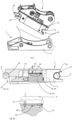
- Figure 1 schematically illustrates a tool holder 2 and a tool 1 that can be connected to one another via a coupling system 12.
- the tool holder 2 is typically coupled to a machine, for example an excavator or forestry machine or the like.
- the tool 1 or tool adapter 1 in the illustrated example is typically arranged on a tool such as a shovel, forestry tool, cutter, compactor or the like.
- the tool 1 or tool adapter 1 is designed so that it can be coupled to the tool holder 2 automatically without manual interreference of an operator at the tool 1 or tool holder 2.
- a frame 8 of the tool holder 2 comprises at least one hook shaped cut out 22 and at least one partial hook shaped cut out 24.
- At least one actuator 18 is embedded and connected, at least with one side, to the frame 8.
- a coupling mechanism 12 comprising the at least one actuator for example in the form of a hydraulic or pneumatic cylinder 18 (c.f. figures 2 and 3 ) connected to lock fingers 20 or a lock element and the at least one hook shaped cut out 22 and the at least one partial hook shaped cut out 24 on the tool holder 2 and a pair of bracket pins 6 on the tool 1 or tool adapter 1, said pair of bracket pins 6 being held together by a body 4 of the tool 1 or tool adapter 1.
- the lock fingers 20 are shown in an at least partially extended state, thus with the at least one actuator 18 at least partially extended.
- the hook shaped cut outs 22 are engaged first in one of the bracket pins 6.
- the tool 1 can be lifted and tilted by the machine via the tool holder 2 so that the at least partially hook shaped cut outs 22 can engage the other of the pair of bracket pins 6, when the lock fingers 20 are retracted and typically due to the tilting movement of the tool due to gravity.
- the lock fingers 20 can be extended so that they lock both bracket pins 6 securely and the tool 1 can be used.
- the coupling does not necessarily need to be established by lifting the tool 1, tilting it on the ground or just smoothly coupling while the tool is laying on the ground may be enough to connect the pair of bracket pins 6 to the tool holder 2 via the coupling mechanism 12.
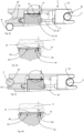
- Figure 2a is a cross sectional view of the tool holder 2 and a part of the tool, namely the pair of bracket pins 6 in order to explain the invention in more detail.
- Figure 2a illustrates how the first bracket pin 6 is snug engaged in the at least one hook shaped cut out 22 and the second bracket pin 6 is snug engaged in the partial hook shaped cut out 24.
- the at least one actuator 18 is in a fully retracted position so that the lock finger 20 does not engage the second bracket pin 6 in the at least one partial hook shaped cut out 24.
- the second bracket pin 6 is therewith not securely locked.
- the piston 28 of the actuator 18 is retracted in the housing 30 of the actuator 18.
- the at least one actuator 18 is connected to the frame 8 via a free end of the piston 28, in particular a rod of the piston 28, so that the housing 30 is moving in relation to the frame 8 when the actuator is extended and retracted.
- the pattern 14 is made of magnetic material or material that can be magnetized.
- Various such materials exist such as ferromagnetic iron, magnetizable aluminium or alloys, which comprise metals that can be magnetized such as iron (Fe), cobalt (Co), nickel (Ni) or even copper (Cu).
- any alloy that is suitable and containing at least one of the named metals may be used to provide the pattern 14.
- an sweep sensor 16 is arranged that can sense the pattern 14.
- the sweep sensor 16 is connected to a processor 32, a memory 34, for example a non-transitory memory, such as computer-readable media (CRM) that stores data for short periods or in the presence of power such as a memory device or Random Access Memory (RAM), a power source 36 and a display or the like 38 to display information, as shown in figure 5 , which figure 5 illustrates an actuator positioning system 10.
- the sweep sensor 16 is designed to sense the shape of the pattern 14 in order to determine the exact position of the actuator 18 in particular the actuator housing 30 and the lock finger(s) 22.
- Figure 2b illustrates the lock finger 20 and therewith the coupling mechanism 12 in the open and not secure position where the second bracket pin 6 is not secured in the hook shaped cut out 24.
- Figure 2b visualizes an enlargement of the area around the metallic pattern 14 and the sweep sensor 16 arranged on the actuator housing 30 of figure 2a , indicated by an elliptic circumference.
- the sweep sensor 16 is embedded in the frame 8 of the tool holder 2.
- sweep sensorThe sweep sensor 16 may be arranged perpendicular or parallel to a plane defined by the pattern 14. From figure 2b it also becomes clear how the sweep sensor 16 together with the processor 32, power source 36 and memory 34, thus with a computer, can determine the position of the lock element 20 or lock finger 20.
- a first section 40 of the metallic pattern 14 is arranged under or within vicinity of the sweep sensor 16.
- the first section 40 of the metallic pattern 14 comprises four (4) vertically cut indentations or pole shaped cut outs which are comparably thin in width as compared to a second section 42 of the metallic pattern 14, which second section comprises five (5) rectangular cut-outs spaced apart wider than the pole shaped cut outs of the first section 40.
- the rectangular cut outs of the second section 42 are also wider than the pole shaped cut outs of the first section 40.
- the sweep sensor 16 thus knows that the lock finger 20 is not yet extended since it can detect the first section 40 of the metallic pattern 14. This may be shown to an operator of a machine via the display 38.
- the state of the coupling mechanism 12 shown in figures 2a and 2b is determined as not safe since the tool can fall from the machine as it is not locked safely.
- the pattern 14 illustrated in figure 2b (and 3b, 4b) is only exemplary and the skilled person understands that many different patterns may be used and employed.
- FIGS 3a and 3b illustrate a similar view as figures 2a and 2b with same reference numbers being used for the same components.
- Figure 3a further illustrates how the piston 28 of the actuator 18 is fully extended with a rod of the piston 28 well visible.
- the housing 30 of the actuator 18 and the lock finger(s) 20 are therewith pushed towards the at least one partial hook shaped cut out 24.
- Figure 3a illustrates an unsafe state of the coupling mechanism 12, where the second bracket pin 6, which is supposed to engage the at least one partial hook shaped cut out 24 is not arranged snug in the partial hook shaped cut out 24 but rather arranged below the frame 8 of the tool holder 2. This can potentially be a very dangerous situation as the operator can normally not see the rear or second bracket pin 6.
- Figure 3b illustrates an enlargement of figure 3a , indicated by the elliptic circumference.
- Figure 3a illustrates fourth section 46 of the metallic pattern 14 is arranged under the sweep sensor 16 or in close vicinity of it.
- the fourth section 46 is designed similar to the first pattern 40 with rather slim pole shaped cut outs, the pole shaped cut outs of the fourth section 46 are however slimmer and closer together as the one from the first section 40.
- the metallic pattern 14 further comprise a third section 44 which third section 44 comprises basically a wider rectangular cut-out and a slimmer pole-shaped cut out. All four sections 40, 42, 44, 46 of the metallic pattern 14 are different and distinguishable from one another so that any relevant position of the actuator 18, the actuator housing 30 and therewith the lock element 20 (c.f.
- FIG 3a can be detected.
- the fourth section 46 and the corresponding signal path or signal curve (c.f. figures 6 to 8 ) makes it possible to detect and clearly distinguish the exact actuator position and the determine that the lock finger 20 is in an over-extended position and that the second bracket pin 6 is therewith not securely locked in the partial hook shaped cut out 24. This can be indicated to the machine operator via a warning, for example via the display 38 (c.f. figure 5 ) or by blocking the controls of the machine, once the pattern 14 is calibrated on the size of the tool holder 2.
- Figures 4a illustrates the coupling mechanism 12 in the properly secured state where the first bracket pin 6 is snug arranged in the hook shaped cut out 22 and the second bracket pin is snug arranged in the partial hook shaped cut out 24 and the lock fingers 20 is properly engaging and therewith locking the second bracket pin 6.
- the actuator 18 is in an extended position but not over-extended as in figure 3a .
- Figure 4b illustrates enlargement of figure 4a , indicated by the elliptic circumference.
- Figure 4a shows the third section 44 of the metallic pattern 14 is positioned under the sweep sensor 16.
- the third section 44 comprises a wider rectangular cut-out and a slimmer pole-shaped cut out directly next to one another.
- This specific design of the third section 44 lets the sweep sensor 16 and a connected processor 32 to detect the closed and locked position of the lock element 20. This is a safe state and the machine and tool may now be used, which can be signalled to the operator for example via the display 38.
- any of the described sections 40, 42, 44, 46 may be removed from the pattern 14 as illustrated in figures 2b , 3b, 4b .
- the fourth section 46 relating to the over-extended lock finger 20 and therewith an over extended state of the coupling mechanism 12 may be removed in another embodiment.
- the metallic pattern 14 may be a ferromagnetic pattern 14.
- a metallic pattern (not shown) with more or less than four (4) sections, whereby each section is distinguishable from the other sections.
- the number of sections depends on the use case and system requirements, such as number of actuator positions that need to be detected and how sensitive the actuator positioning system needs to be.
- the sections 40, 42, 44, 46 illustrated in figures 2a to 4b are rather basic. Other sections and therewith other metallic patterns may of course be used. Such other patterns may for example comprise curved surfaces, inclined surfaces and even different heights.
- the sweep sensor 16 is designed to measure at least more less perpendicular to a surface of the housing 30. It may however be inclined to the surface of the housing 30 as long it can follow and therewith detect and observe the metallic pattern 14 in order to provide positioning information of the actuator 18.
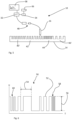
- FIG. 5 illustrates the actuator positioning system 10 according to the invention.
- the actuator positioning system 10 comprises the processor 32, the energy source 36, the memory 34, the display, the sweep sensor 16 and the pattern 14.
- the sweep sensor 16 and the pattern 14 are arranged on the tool holder (not shown in figure 5 ) and the sweep sensor 16 may be releasably connected to the processor 32 or computer, as indicated by the plugs and socket 48 during coupling and decoupling of the tool holder to the machine.
- the computer thus the processor 32, the memory 34, the energy source 36 and the display 38 may be part of the machine or they may be integrated in the tool holder 2. It is even possible to send the signal from the sweep sensor 14 in a wireless manner to the processor or computer.
- the computer may be arranged at any suitable position, for example in the cabin of the machine or at a central control centre.
- At least the display 38 is typically arranged in a cabin of the machine so that the operator can get information.
- the pattern 14 illustrated in figure 5 comprises four (4) sections 40', 42', 44' and 46', which are slightly different from the sections explained referring to figures 2a to 4b .
- the length of the pattern 14 may correspond at least to a stroke length of the actuator 18 so that the sweep sensor 16 can detect the pattern 14 along the entire stroke length of the actuator 18.
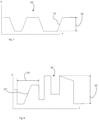
- FIGS. 6 to 8 show various curve shapes that can be provided via the computer, thus the processor 32 and memory 34, using information provided by the sweep sensor 14 and the pattern 16.
- Figure 6 illustrates a classical pulse curve 50 generated via the sweep sensor 16 and the pattern 14 in the housing 30 as explained referring to figures 2a to 5 .
- the classical pulse curve 50 may be analysed and interpreted by a computer, such as the memory 34, the processor 32 and the energy source 36 illustrated in figure 5 .
- the y-axis illustrates the Amplitude U and the x-axis illustrates the time T.
- the Amplitude U is typically given in voltage while the time T is typically given in seconds. Other dimensions than voltage and seconds may however be used.
- the classical pulse curve 50 allows to determine the exact position of the actuator 18 by analysing the pulses 52 and the periods 54 of the curve 50.
- the curve 50 illustrated in figure 6 also shows the actual amplitude 56 of the curve 50.
- the amplitude 56 may be directly proportional to the depth of the pattern 14 shown in figures 2a to 5 or it may be amplified or modified.
- figure 6 illustrates a first part 58 of the curve that may for example correspond to the fourth section 46 as illustrated in figures 2b , 3b and 4b while a second part 60 of the curve may correspond to the first section 40.
- the computer may now conclude that the actuator 18 is a fully retracted state since the curve 50 went from the fourth section 46, corresponding to the first part 58 (lock finger 20 in locked and secure position), to the first section 40 corresponding to the second part 60 (lock finger 20 in retracted and open position).
- the curve 50 allows to detect the exact position of the lock finger 20 and therewith the actuator at any point in time, no matter whether the actuator 18 is moving or in an idle position. Having an irregular pattern 14 with several different sections 40, 42, 44, 46 allows to determine very quickly and efficiently at which position the actuator 18 is at even after a current power loss or during rebooting or restarting of the machine.
- Figure 7 illustrates another curve 50' with inclined or sloped pulses 52' that also have one and the same amplitude 56' like the amplitude 56 of figure 6 .
- the inclined pulses may be amplified or generated based on time and speed of movement, thus digitalized, or they may be generated directly by designing the pattern 14 accordingly with inclined surfaces.
- Figure 8 illustrates another example of a curve 50" showing a combination of the curves 50, 50' illustrated in figures 6 and 7 , with varying amplitudes 56" and included surfaces 52".
- This curve may be obtained digitally using an algorithm based on signals provided by the sweep sensor 16 or it may be directly obtained from the pattern 14.
- curves 50, 50', 50" shown in figures 6 to 8 it is also possible to obtain curves that comprise sinus shaped elements alone or in combination with parts of the curves 50, 50', 50" as illustrated.
- digital tools and physical pattern generating technologies such as lasering, sputtering, milling, 3D printing and so on allow to generate a variety of suitable and useful patterns on the housing 30 of the actuator 18 or the actuator 18.
- the actuator 18 may be a hydraulic or pneumatic cylinder comprising at least two hydraulic or pneumatic cylinders with a H-shaped housing (not shown) whereby each leg of the H-shape comprises one cylinder. The free ends of the cylinder may thereby be connected to the frame of the tool holder.
- the pattern may be directly produced on or in the housing 30 of the actuator 18 for example by lasering, sputtering, milling, 3D printing or any similar method.
- a strip of material that is treated according to any of the above-described methods and comprises the pattern 14, may be glued, bolted, screwed, clamped or welded onto the housing 30 of the actuator 18.
- a releasable connection of the pattern 14 to the housing 30, such as screwing or clamping, may be desirable so that the pattern 14 can actually be replaced in case the use-case changes or in change another pattern 14 need to be used.
- Figure 9 illustrates a method for extracting information relating to the state of an actuator 18 and a coupling mechanism 12, respectively, in a tool holder 2.
- the method comprises the steps of:
- the information that can be extracted from the curve 50, 50', 50" or the actual signal may be positioning information, as described above.
- the information may however also be information related to the speed of movement of the actuator thus, how quick the actuator 18 moving between the various positions. This may allow to draw conclusions regarding hydraulic or pneumatic pressure in the hydraulic or pneumatic system and if fluid or hydraulic fluid needs to be added to the system. Further, the generation of the curve may be avoided if the signal can be compared to previous values and a stored database. This alone may be enough to extract positioning information from the signal.
- the signal or surface may be continuously read or swept SO1 by the sweep sensor.
- Reading the signal over time may mean that a measurement is performed by the sweep sensor 16 at regular time intervals.
- the intervals may be chosen to be rather small time periods and preferably in the millisecond range or shorter, in particular towards the end positions, coupling mechanism 12 open and coupling mechanism 12 securely closed,
Landscapes
- Engineering & Computer Science (AREA)
- Mechanical Engineering (AREA)
- General Engineering & Computer Science (AREA)
- Mining & Mineral Resources (AREA)
- Civil Engineering (AREA)
- Structural Engineering (AREA)
- Physics & Mathematics (AREA)
- Fluid Mechanics (AREA)
- General Physics & Mathematics (AREA)
- Electromagnetism (AREA)
- Machine Tool Sensing Apparatuses (AREA)
- Numerical Control (AREA)
- Shovels (AREA)
Priority Applications (5)
| Application Number | Priority Date | Filing Date | Title |
|---|---|---|---|
| EP22209884.0A EP4375426A1 (de) | 2022-11-28 | 2022-11-28 | Werkzeughalter für eine maschine mit einem positionierungssystem |
| KR1020230162374A KR20240079158A (ko) | 2022-11-28 | 2023-11-21 | 포지셔닝 시스템을 구비하는 기계용 툴 홀더 |
| JP2023198369A JP2024077616A (ja) | 2022-11-28 | 2023-11-22 | 位置決めシステムを有する機械用の工具ホルダ |
| CA3220979A CA3220979A1 (en) | 2022-11-28 | 2023-11-24 | Tool holder for a machine with a positioning system |
| US18/521,359 US20240175233A1 (en) | 2022-11-28 | 2023-11-28 | Tool holder for a machine with a positioning system |
Applications Claiming Priority (1)
| Application Number | Priority Date | Filing Date | Title |
|---|---|---|---|
| EP22209884.0A EP4375426A1 (de) | 2022-11-28 | 2022-11-28 | Werkzeughalter für eine maschine mit einem positionierungssystem |
Publications (1)
| Publication Number | Publication Date |
|---|---|
| EP4375426A1 true EP4375426A1 (de) | 2024-05-29 |
Family
ID=84364259
Family Applications (1)
| Application Number | Title | Priority Date | Filing Date |
|---|---|---|---|
| EP22209884.0A Pending EP4375426A1 (de) | 2022-11-28 | 2022-11-28 | Werkzeughalter für eine maschine mit einem positionierungssystem |
Country Status (5)
| Country | Link |
|---|---|
| US (1) | US20240175233A1 (de) |
| EP (1) | EP4375426A1 (de) |
| JP (1) | JP2024077616A (de) |
| KR (1) | KR20240079158A (de) |
| CA (1) | CA3220979A1 (de) |
Citations (6)
| Publication number | Priority date | Publication date | Assignee | Title |
|---|---|---|---|---|
| US5497083A (en) * | 1992-12-24 | 1996-03-05 | Kayaba Kogyo Kabushiki Kaisha | Rod axial position detector including a first scale having equidistant magnetic parts and a second scale having unequally distant parts and differing field strengths |
| WO2009078048A1 (en) * | 2007-12-19 | 2009-06-25 | Roaldo Alberton | Method for establishing the dynamic position of a mechanical translation actuator and related encoder |
| DE102010060550A1 (de) | 2010-11-15 | 2012-05-16 | Sick Ag | Sensor mit Verschleißerkennung |
| AU2014202627A1 (en) * | 2013-05-14 | 2014-12-04 | Kuo-Chieh Liao | Coupling device |
| EP2846126A1 (de) | 2013-09-04 | 2015-03-11 | Bogen Electronic GmbH | Messvorrichtung und Verfahren zum Messen der Position von Körpern |
| US10895057B2 (en) * | 2016-05-23 | 2021-01-19 | Hiltec Designs Ltd. | Coupler with contactless attachment engagement detection |
-
2022
- 2022-11-28 EP EP22209884.0A patent/EP4375426A1/de active Pending
-
2023
- 2023-11-21 KR KR1020230162374A patent/KR20240079158A/ko unknown
- 2023-11-22 JP JP2023198369A patent/JP2024077616A/ja active Pending
- 2023-11-24 CA CA3220979A patent/CA3220979A1/en active Pending
- 2023-11-28 US US18/521,359 patent/US20240175233A1/en active Pending
Patent Citations (6)
| Publication number | Priority date | Publication date | Assignee | Title |
|---|---|---|---|---|
| US5497083A (en) * | 1992-12-24 | 1996-03-05 | Kayaba Kogyo Kabushiki Kaisha | Rod axial position detector including a first scale having equidistant magnetic parts and a second scale having unequally distant parts and differing field strengths |
| WO2009078048A1 (en) * | 2007-12-19 | 2009-06-25 | Roaldo Alberton | Method for establishing the dynamic position of a mechanical translation actuator and related encoder |
| DE102010060550A1 (de) | 2010-11-15 | 2012-05-16 | Sick Ag | Sensor mit Verschleißerkennung |
| AU2014202627A1 (en) * | 2013-05-14 | 2014-12-04 | Kuo-Chieh Liao | Coupling device |
| EP2846126A1 (de) | 2013-09-04 | 2015-03-11 | Bogen Electronic GmbH | Messvorrichtung und Verfahren zum Messen der Position von Körpern |
| US10895057B2 (en) * | 2016-05-23 | 2021-01-19 | Hiltec Designs Ltd. | Coupler with contactless attachment engagement detection |
Also Published As
| Publication number | Publication date |
|---|---|
| JP2024077616A (ja) | 2024-06-07 |
| US20240175233A1 (en) | 2024-05-30 |
| CA3220979A1 (en) | 2024-05-28 |
| KR20240079158A (ko) | 2024-06-04 |
Similar Documents
| Publication | Publication Date | Title |
|---|---|---|
| EP2029967B2 (de) | Verfahren zur messung eines objekts | |
| US10895057B2 (en) | Coupler with contactless attachment engagement detection | |
| EP1899678B1 (de) | System und verfahren zur messung und abbildung einer oberfläche relativ zu einer referenz | |
| AU2017387164B2 (en) | Autonomous monitoring system based on magnetic field variation, which allows uncrushable material to be predicted, anticipated and detected in real time and associated methods | |
| EP3118583B1 (de) | Modulare abdichtungsvorrichtung mit fehlererkennungseinheit | |
| WO2015060730A1 (en) | Improvements in and relating to couplers | |
| US20140308061A1 (en) | Method and System for Detecting Engagement with a Work Tool Accessory | |
| EP4375426A1 (de) | Werkzeughalter für eine maschine mit einem positionierungssystem | |
| JP2019518155A (ja) | 掘削工程の効率判定用システム及び方法 | |
| Gao et al. | Mechanical damage in pipelines: a review of the methods and improvements in characterization, evaluation, and mitigation | |
| CN110363756A (zh) | 一种用于磨头的磨损检测系统及检测方法 | |
| CN106123732A (zh) | 一种自动化位置度检测设备 | |
| CN103245274A (zh) | 气瓶瓶口内径量具 | |
| EP3209973B1 (de) | Magnetoresistiver näherungssensor | |
| EP0829699B1 (de) | Verfahren und System zur Messung dreidimensionaler Verschiebungen | |
| US6879404B2 (en) | Device and method for checking bores in or edges on an object of measurement | |
| CN206160906U (zh) | 待焊接工件的穿孔检测装置 | |
| CA2820101A1 (en) | Detector system of slickline irregularities | |
| US4114429A (en) | Method of and apparatus for sensing strain in strained members | |
| US8049495B2 (en) | Probe for a magnetic remanence measurement method, and method for detecting deposits of foreign material and inclusions in hollow spaces | |
| CN214887036U (zh) | 铁磁性物体检测装置 | |
| JP6912604B2 (ja) | 座標系統合方法、及び柱状体を備える装置 | |
| CN205580896U (zh) | 一种摆锤式冲击试验机用刀刃对中定位器 | |
| CN216240605U (zh) | 检测装置及具有其的井口系统 | |
| CN109238089A (zh) | 一种用于检测热轧叉车横梁型钢尺寸的检测工具 |
Legal Events
| Date | Code | Title | Description |
|---|---|---|---|
| PUAI | Public reference made under article 153(3) epc to a published international application that has entered the european phase |
Free format text: ORIGINAL CODE: 0009012 |
|
| STAA | Information on the status of an ep patent application or granted ep patent |
Free format text: STATUS: THE APPLICATION HAS BEEN PUBLISHED |
|
| AK | Designated contracting states |
Kind code of ref document: A1 Designated state(s): AL AT BE BG CH CY CZ DE DK EE ES FI FR GB GR HR HU IE IS IT LI LT LU LV MC ME MK MT NL NO PL PT RO RS SE SI SK SM TR |