EP3763473A1 - Structure d'assemblage et procédé d'assemblage - Google Patents
Structure d'assemblage et procédé d'assemblage Download PDFInfo
- Publication number
- EP3763473A1 EP3763473A1 EP18908403.1A EP18908403A EP3763473A1 EP 3763473 A1 EP3763473 A1 EP 3763473A1 EP 18908403 A EP18908403 A EP 18908403A EP 3763473 A1 EP3763473 A1 EP 3763473A1
- Authority
- EP
- European Patent Office
- Prior art keywords
- protrusion
- outer peripheral
- welded
- overlapping portion
- peripheral portion
- Prior art date
- Legal status (The legal status is an assumption and is not a legal conclusion. Google has not performed a legal analysis and makes no representation as to the accuracy of the status listed.)
- Pending
Links
Images

Classifications
-
- B—PERFORMING OPERATIONS; TRANSPORTING
- B23—MACHINE TOOLS; METAL-WORKING NOT OTHERWISE PROVIDED FOR
- B23K—SOLDERING OR UNSOLDERING; WELDING; CLADDING OR PLATING BY SOLDERING OR WELDING; CUTTING BY APPLYING HEAT LOCALLY, e.g. FLAME CUTTING; WORKING BY LASER BEAM
- B23K26/00—Working by laser beam, e.g. welding, cutting or boring
- B23K26/20—Bonding
- B23K26/21—Bonding by welding
- B23K26/24—Seam welding
- B23K26/242—Fillet welding, i.e. involving a weld of substantially triangular cross section joining two parts
-
- B—PERFORMING OPERATIONS; TRANSPORTING
- B23—MACHINE TOOLS; METAL-WORKING NOT OTHERWISE PROVIDED FOR
- B23K—SOLDERING OR UNSOLDERING; WELDING; CLADDING OR PLATING BY SOLDERING OR WELDING; CUTTING BY APPLYING HEAT LOCALLY, e.g. FLAME CUTTING; WORKING BY LASER BEAM
- B23K26/00—Working by laser beam, e.g. welding, cutting or boring
- B23K26/20—Bonding
- B23K26/21—Bonding by welding
- B23K26/24—Seam welding
- B23K26/244—Overlap seam welding
-
- B—PERFORMING OPERATIONS; TRANSPORTING
- B23—MACHINE TOOLS; METAL-WORKING NOT OTHERWISE PROVIDED FOR
- B23K—SOLDERING OR UNSOLDERING; WELDING; CLADDING OR PLATING BY SOLDERING OR WELDING; CUTTING BY APPLYING HEAT LOCALLY, e.g. FLAME CUTTING; WORKING BY LASER BEAM
- B23K26/00—Working by laser beam, e.g. welding, cutting or boring
- B23K26/20—Bonding
- B23K26/32—Bonding taking account of the properties of the material involved
- B23K26/323—Bonding taking account of the properties of the material involved involving parts made of dissimilar metallic material
-
- B—PERFORMING OPERATIONS; TRANSPORTING
- B23—MACHINE TOOLS; METAL-WORKING NOT OTHERWISE PROVIDED FOR
- B23K—SOLDERING OR UNSOLDERING; WELDING; CLADDING OR PLATING BY SOLDERING OR WELDING; CUTTING BY APPLYING HEAT LOCALLY, e.g. FLAME CUTTING; WORKING BY LASER BEAM
- B23K2103/00—Materials to be soldered, welded or cut
- B23K2103/18—Dissimilar materials
Definitions
- the present disclosure relates to a joining structure and a joining method.
- PATENT DOCUMENT 1 International Patent Publication No. WO2017/170517
- the present disclosure has been devised and it is therefore an object of the present disclosure to restrain the occurrence of an electrolytic corrosion in a portion in which metal materials of the same type and a material of a different type overlap.
- Each aspect of the present disclosure is directed to a joining structure including a first member formed of a metal material, a second member formed of a metal material of a same type as that of the first member which can be welded to the first member, and a third member formed of a material that is difficult to weld to the first member and the second member, the first member, the second member, and the third member being jointed to each other, and the following solutions have been devised.
- a first aspect is characterized in that, in the joining structure, a protrusion is provided in at least one of the first member and the second member, a through portion in which the protrusion is inserted is formed in the third member, the first member and the second member are welded to each other via the through portion with the third member interposed therebetween in a region corresponding to the protrusion, and each of an outer peripheral portion of an overlapping portion of the first member and the third member and an outer peripheral portion of an overlapping portion of the second member and the third member is welded.
- the first member and the second member are formed of metal materials of the same type and the third member is formed of a material of a different type which is difficult to weld to the first member and the second member.
- the first member and the second member are welded to each other via the through portion with the third member interposed therebetween in the region corresponding to the protrusion.
- each of the respective outer peripheral portions of the overlapping portion of the first member and the third member and the overlapping portion of and the second member and the third member is welded.
- a second aspect is characterized in that, in the joining structure of the first aspect, the regions of the first member and the second member corresponding to the protrusion, the outer peripheral portion of the overlapping portion of the first member and the third member, and the outer peripheral portion of the overlapping portion of the second member and the third member are laser-welded to each.
- joining of the first member, the second member, and the third member may be performed by laser welding.
- a third aspect is characterized in that, in the joining structure of the second aspect, the regions of the first member and the second member corresponding to the protrusion, the outer peripheral portion of the overlapping portion of the first member and the third member, and the outer peripheral portion of the overlapping portion of the second member and the third member are laser-welded to each by radiating laser light from either of one member side among the first member, the second member, and the third member, which is formed of a material having a high laser absorption rate.
- the laser light may be radiated from either of one member side among the first member, the second member, and the third member, which is formed of a material having a high laser absorption rate.
- welding may be performed by radiating the laser light from a side in which the first material and the second member are provided, because the soft steel material has a lower reflectance to the laser light than that of the aluminum material, that is, the soft steel material has a higher laser absorption rate than that of the aluminum material.
- energy of the laser light can be efficiently absorbed, and the first member, the second member, and the third member can be sufficiently melted.
- a fourth aspect is characterized in that, in the joining structure of the first aspect, the regions of the first member and the second member corresponding to the protrusion are laser-welded, and the outer peripheral portion of the overlapping portion of the first member and the third member and the outer peripheral portion of the overlapping portion of the second member and the third member is welded using a filler material to each.
- joining of the first member and the second member may be performed by laser welding, and joining of the outer peripheral portion of the first member and the third member and joining of the outer peripheral portion of the second member and the third member may be performed by welding using a filler material, such as, for example, arc welding or laser filler welding.
- a filler material such as, for example, arc welding or laser filler welding.
- a fifth aspect is directed to a joining method, in which a first member formed of a metal material, a second member formed of a metal material of a same type as that of the first member which can be welded to the first member, and a third member formed of a material that is difficult to weld to the first member and the second member are joined to each other, at least one of the first member and the second member being configured such that a protrusion is provided therein, the third member being configured such that a through portion in which the protrusion is inserted is formed therein, and is characterized by including steps of inserting the protrusion in the through portion of the third member and interposing the third member between the first member and the second member, welding the first member and the second member to each other via the through portion by radiating laser light to a region corresponding to the protrusion, and welding each of an outer peripheral portion of an overlapping portion of the first member and the third member and an outer peripheral portion of an overlapping portion of the second member and the third member.
- the first member and the second member are formed of metal materials of the same type and the third member is formed of a material of a different type which is difficult to weld to the first member and the second member.
- the first member and the second member are welded to each other via the through portion with the third member interposed therebetween in the region corresponding to the protrusion.
- each of the respective outer peripheral portions of the overlapping portion of the first member and the third member and the overlapping portion of and the second member and the third member is welded.
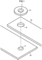
- a first member 10, a second member 20, and a third member 30 are disposed in a state in which the third member 30 is interposed between the first member 10 and the second member 20.
- the first member 10 is a disk-like member formed of a metal material, and a first protrusion 11 having an embossed shape is formed so as to be tapered and protrude toward the second member 20 in a central portion of the first member 10.
- the second member 20 is a plate-like member formed of a metal material of the same type as that of the first member 10 which can be welded to the first member 10, and a second protrusion 21 having an embossed shape is formed so as to be tapered and protrude toward the first member 10 therein.
- the third member 30 is a plate-like member formed of a material that is difficult to weld to the first member 10 and the second member 20, and a through hole 31 as a through portion is formed therein. Note that, although the through hole 31 is provided as the through portion, the through portion may be a through groove. In performing joining, the third member 30 that is a material of a different type is disposed so as to be interposed between the first member 10 and the second member 20 that are metal materials of the same type.
- the first protrusion 11 and the second protrusion 21 are disposed so as to be inserted in the through hole 31 of the third member 30 and to face to each other.
- the first protrusion 11 and the second protrusion 21 are inserted in the through hole 31 of the third member 30, and therefore, the through hole 31 has an effect of restraining relative positional displacement of the first member 10 and the second member 20 with respect to the through hole 31.
- the first protrusion 11 that a mark of a laser irradiation position and propriety of a bead forming position can be visually checked.
- the "metal materials of the same type” mean metals that can be welded to each other and may be not only the same material but also metal materials, such as ferrous metal materials, nonferrous metal materials, or the like, which have a good weld joining property.
- the "metal materials of the same type” mean materials of the same type which have good compatibility in welding.
- combinations of the first member 10 and the second member 20 in performing welding are as follows.
- ferrous metal materials there are combinations of soft steel and soft steel, stainless and stainless, soft steel and high tensile steel, high tensile steel and high tensile steel, and the like.
- nonferrous metal materials there are combinations of aluminum and aluminum, aluminum and aluminum alloy, aluminum alloy and aluminum alloy, and the like.
- the third member 30 as a material of a different type is a different material from those of the first member 10 and the second member 20 as metal materials of the same type and is a material that is difficult to weld to the first member 10 and the second member 20.
- the third member 30 as a material of a different type is a nonferrous metal material, such as a copper material, an aluminum material, or the like, which has a low laser light absorptivity and is difficult to laser-weld.
- a material of a different type from the metal materials include a resin material, such as carbon fiber reinforced plastics (CFRP), polyethylene terephthalate (PET), or the like.
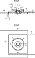
- the first protrusion 11 and the second protrusion 21 are inserted in the through hole 31 of the third member 30 and are disposed so as to face to each other in a plate-thickness direction with a predetermined space therebetween.
- joining of the first member 10 and the second member 20 is performed by laser welding.
- laser welding is performed by radiating laser light L in a circular shape toward a region corresponding to the first protrusion 11, that is, a region (a joinable range) that can be irradiated with the laser light L, from an upper side of the first member 10 in the plate-thickness direction.
- the laser light L is radiated in the plate-thickness direction in a state before welding in which the gap exists, the first member 10 and the second member 20 as metal materials of the same type are melt and jointed to each other and then solidified and shrunk, and the third member 30 as a material of a different type interposed therebetween is compressed and fixed.
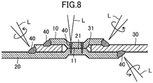
- the third member 30 that is a material of a different type is interposed between the first member 10 and the second member 20 that are metal materials of the same type, there is a probability that moisture enters a portion in which the first member 10, the second member 20, and the third member 30 overlap, so that an electrolytic corrosion occurs.
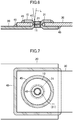
- each of an outer peripheral portion of an overlapping portion of the first member 10 and the third member 30 and an outer peripheral portion of an overlapping portion of the second member 20 and the third member 30 is welded.
- the laser light L is radiated in a circular shape from the upper side of the first member 10 in the plate-thickness direction along the outer peripheral portion of the overlapping portion of the first member 10 and the third member 30.
- the first member 10 and the third member 30 are melted to form the welded portion 40, and a sealed joining structure in which a gap between the first member 10 and the third member 30 in an overlapping direction is filled can be achieved.
- the first member 10, the second member 20, and the third member 30 may be melted and jointed to each other, for example, radiating the laser light L such that the laser light L reaches the third member 3.
- laser welding is performed by radiating the laser light L from a side which is formed of a material having a high laser absorption rate.
- the second member 20 is formed of a soft steel material and the third member 30 is formed of an aluminum material
- laser welding is performed by radiating the laser light L in a quadrangular shape from a lower side of the second member 20 in the plate-thickness direction along the outer peripheral potion of the overlapping portion of the first member 10 and the third member 30, because the soft steel material has a lower reflectance to the laser light L than that of the aluminum material, that is, the soft steel material has a higher laser absorption rate than that of the aluminum material.
- energy of the laser light L can be efficiently absorbed, and the second member 20 and the third member 30 can be sufficiently melted.
- a penetration depth d from an overlapping surface of the third member 30 located in an opposite side to a side that is irradiated with the laser light L may be a depth that is equal to or larger than 20% of a plate thickness t of the third member 30.
- the laser light L can be kept from passing through the third member 30 and airtightness can be ensured. Note that similar applies to the penetration depths in the first member 10 and the third member 30.
- FIG. 6 is a cross-sectional view illustrating a joining structure after welding according to a second embodiment.
- the same components as those in the first embodiment will be denoted by the same reference symbols as those in the first embodiment and only different points will be described below.
- the welded portion 40 is formed by radiating the laser light L in a circular shape to a region corresponding to the first protrusion 11 and the second protrusion 21 from an upper side in the plate-thickness direction.
- the first member 10 and the second member 20 are laser-welded.
- the outer peripheral portion of the overlapping portion of the first member 10 and the third member 30 is welded using a filler material. Specifically, arc welding or laser filler welding is performed along an outer peripheral corner portion of the overlapping portion of the first member 10 and the third member 30. Note that, in a case in which the first member 10 is a soft steel material and the third member 30 is an aluminum material, it is necessary to use a filler material exclusively used for materials of different types with which the soft steel material and the aluminum material can be welded.
- the outer peripheral portion of the overlapping portion of the second member 20 and the third member 30 is welded using a filler material. Specifically, arc welding or laser filler welding is performed along an outer peripheral corner of the overlapping portion of the second member 20 and the third member 30.
- a sealed joining structure in which the gap between the second member 20 and the third member 30 in the overlapping direction is filled with the welded portion 45 formed of the filler material that has been melt and jointed can be achieved.
- the first protrusion 11 and the second protrusion 21 have the same shape, but the first protrusion 11 and the second protrusion 21 may have different shapes. Moreover, a protrusion is provided in each of both the first member 10 and the second member 20, but a protrusion may be provided only one of the first member 10 and the second member 20.
- the laser light L is radiated from a side in which the first member 10 is provided, but the laser light L may be radiated from a side in which the second member 20 is provided.
- the materials of the first member 10 and the second member 20 are metal materials of the same type and, for example, a case in which a soft steel material is used for each of the first member 10 and the second member 20 has been described.
- different materials may be used for the first member 10 and the second member 20 as long as the materials are metal materials of the same type which can be welded to each other and can achieve an enough joining strength.
- arc welding or laser filler welding using a filler material is performed on the outer peripheral portion of the overlapping portion of the first member 10 and the third member 30 and the outer peripheral portion of the overlapping portion of the second member 20 and the third member 30.
- the present disclosure is not limited to this form.
- the outer peripheral corner portion may be melted, and thus, the first member 10 and the third member 30 may be welded. Note that, for the outer peripheral corner portion of the overlapping portion of the second member 20 and the third member 30, welding may be performed in a similar manner.
- the present disclosure As described above, according to the present disclosure, a highly practical effect that the occurrence of an electrolytic corrosion in a portion in which metal materials of the same type and a material of a different type overlap can be restrained is achieved, and therefore, the present disclosure is very useful and has high industrial applicability.
Landscapes
- Physics & Mathematics (AREA)
- Optics & Photonics (AREA)
- Engineering & Computer Science (AREA)
- Plasma & Fusion (AREA)
- Mechanical Engineering (AREA)
- Laser Beam Processing (AREA)
Applications Claiming Priority (2)
| Application Number | Priority Date | Filing Date | Title |
|---|---|---|---|
| JP2018038911 | 2018-03-05 | ||
| PCT/JP2018/041378 WO2019171659A1 (fr) | 2018-03-05 | 2018-11-07 | Structure d'assemblage et procédé d'assemblage |
Publications (2)
| Publication Number | Publication Date |
|---|---|
| EP3763473A1 true EP3763473A1 (fr) | 2021-01-13 |
| EP3763473A4 EP3763473A4 (fr) | 2021-04-28 |
Family
ID=67847029
Family Applications (1)
| Application Number | Title | Priority Date | Filing Date |
|---|---|---|---|
| EP18908403.1A Pending EP3763473A4 (fr) | 2018-03-05 | 2018-11-07 | Structure d'assemblage et procédé d'assemblage |
Country Status (5)
| Country | Link |
|---|---|
| US (1) | US11806809B2 (fr) |
| EP (1) | EP3763473A4 (fr) |
| JP (1) | JP7186370B2 (fr) |
| CN (1) | CN111819025B (fr) |
| WO (1) | WO2019171659A1 (fr) |
Families Citing this family (2)
| Publication number | Priority date | Publication date | Assignee | Title |
|---|---|---|---|---|
| JP7557675B2 (ja) * | 2019-04-19 | 2024-09-30 | パナソニックIpマネジメント株式会社 | 接合構造 |
| US20230039275A1 (en) * | 2019-12-13 | 2023-02-09 | Shindengen Electric Manufacturing Co., Ltd. | Welding method and welded structure |
Family Cites Families (17)
| Publication number | Priority date | Publication date | Assignee | Title |
|---|---|---|---|---|
| JPS587850B2 (ja) * | 1977-10-03 | 1983-02-12 | トヨタ自動車株式会社 | 金属材と非金属材の接合構造 |
| US5448831A (en) | 1993-11-08 | 1995-09-12 | Ap Parts Manufacturing Company | Method of manufacturing a stamp formed muffler with hermetically sealed laminated outer shell |
| JP3763525B2 (ja) * | 2002-03-29 | 2006-04-05 | 本田技研工業株式会社 | 溶接方法および溶接装置 |
| JP2006035285A (ja) * | 2004-07-29 | 2006-02-09 | Nissan Motor Co Ltd | 高エネルギビームによる異種材料の重ね接合方法及び重ね接合部材 |
| JP4645298B2 (ja) * | 2005-05-16 | 2011-03-09 | 日産自動車株式会社 | レーザ溶接方法およびレーザ溶接構造 |
| WO2007108079A1 (fr) * | 2006-03-17 | 2007-09-27 | Kabushiki Kaisha Kobe Seiko Sho | Metal de charge pour lier differents materiaux et procede pour lier differents materiaux |
| JP4957093B2 (ja) | 2006-06-29 | 2012-06-20 | 日産自動車株式会社 | 異種金属の接合方法 |
| US7666541B2 (en) | 2006-11-03 | 2010-02-23 | The Gillette Company | Ultrasonic metal welding techniques and batteries manufactured using such techniques |
| DE102007002856B4 (de) * | 2007-01-15 | 2012-02-09 | Edag Gmbh & Co. Kgaa | Vorrichtung zum Bördeln und Schweißen oder Löten von Bauteilen |
| US7819452B2 (en) * | 2008-05-12 | 2010-10-26 | United States Council For Automotive Research | Automotive structural joint and method of making same |
| JP6022402B2 (ja) * | 2013-05-22 | 2016-11-09 | 株式会社神戸製鋼所 | リベット接合構造体及びその製造方法 |
| JP5729429B2 (ja) * | 2013-07-29 | 2015-06-03 | トヨタ自動車株式会社 | 接合構造、及び接合構造の製造方法 |
| US10384296B2 (en) | 2014-12-15 | 2019-08-20 | Arconic Inc. | Resistance welding fastener, apparatus and methods for joining similar and dissimilar materials |
| US10981246B2 (en) | 2016-03-30 | 2021-04-20 | Panasonic Intellectual Property Management Co., Ltd. | Laser welding method |
| US20200298340A1 (en) | 2016-03-30 | 2020-09-24 | Panasonic Intellectual Property Management Co., Ltd. | Joint structure |
| WO2017170518A1 (fr) | 2016-03-30 | 2017-10-05 | パナソニックIpマネジメント株式会社 | Structure de raccord |
| JP2018051570A (ja) | 2016-09-26 | 2018-04-05 | 株式会社神戸製鋼所 | 異材接合用スポット溶接法、接合補助部材、及び、異材溶接継手 |
-
2018
- 2018-11-07 EP EP18908403.1A patent/EP3763473A4/fr active Pending
- 2018-11-07 WO PCT/JP2018/041378 patent/WO2019171659A1/fr unknown
- 2018-11-07 CN CN201880090763.6A patent/CN111819025B/zh active Active
- 2018-11-07 JP JP2020504775A patent/JP7186370B2/ja active Active
-
2020
- 2020-09-03 US US17/011,557 patent/US11806809B2/en active Active
Also Published As
| Publication number | Publication date |
|---|---|
| CN111819025A (zh) | 2020-10-23 |
| CN111819025B (zh) | 2022-08-09 |
| US11806809B2 (en) | 2023-11-07 |
| EP3763473A4 (fr) | 2021-04-28 |
| US20200398378A1 (en) | 2020-12-24 |
| JP7186370B2 (ja) | 2022-12-09 |
| JPWO2019171659A1 (ja) | 2021-03-04 |
| WO2019171659A1 (fr) | 2019-09-12 |
Similar Documents
| Publication | Publication Date | Title |
|---|---|---|
| US11806809B2 (en) | Joining structure and joining method | |
| US20210388859A1 (en) | Joint structure | |
| CN108778609B (zh) | 接合结构 | |
| US20140124489A1 (en) | Hybrid Welding Method of Laser Welding and Arc Welding for T-Joint | |
| WO2018056172A1 (fr) | Procédé de soudage par points destiné à l'assemblage de différents matériaux, élément auxiliaire d'assemblage et assemblage par soudage de différents matériaux | |
| CN110234463B (zh) | 接合结构 | |
| JP6085058B1 (ja) | 電池缶及び電池 | |
| KR20120009510A (ko) | 레이저 용접 방법 및 그것을 포함하는 전지의 제조 방법 | |
| EP2859986A1 (fr) | Dispositif de soudage, procédé de soudage et procédé de production de cellule | |
| CN108883500B (zh) | 激光焊接方法 | |
| EP3438473B1 (fr) | Structure de raccord | |
| CN109070269B (zh) | 接合结构 | |
| JP4232024B2 (ja) | 溶接ビード構造及び溶接方法 | |
| JP7349688B2 (ja) | 接合構造及び接合方法 | |
| JP7546208B2 (ja) | 接合構造 | |
| EP3763474A1 (fr) | Structure de jonction et procédé de jonction | |
| JP2009202226A (ja) | 低出力レーザの溶接構造 |
Legal Events
| Date | Code | Title | Description |
|---|---|---|---|
| STAA | Information on the status of an ep patent application or granted ep patent |
Free format text: STATUS: THE INTERNATIONAL PUBLICATION HAS BEEN MADE |
|
| PUAI | Public reference made under article 153(3) epc to a published international application that has entered the european phase |
Free format text: ORIGINAL CODE: 0009012 |
|
| STAA | Information on the status of an ep patent application or granted ep patent |
Free format text: STATUS: REQUEST FOR EXAMINATION WAS MADE |
|
| 17P | Request for examination filed |
Effective date: 20200904 |
|
| AK | Designated contracting states |
Kind code of ref document: A1 Designated state(s): AL AT BE BG CH CY CZ DE DK EE ES FI FR GB GR HR HU IE IS IT LI LT LU LV MC MK MT NL NO PL PT RO RS SE SI SK SM TR |
|
| AX | Request for extension of the european patent |
Extension state: BA ME |
|
| A4 | Supplementary search report drawn up and despatched |
Effective date: 20210325 |
|
| RIC1 | Information provided on ipc code assigned before grant |
Ipc: B23K 26/323 20140101AFI20210319BHEP Ipc: B23K 26/244 20140101ALI20210319BHEP Ipc: B23K 26/242 20140101ALI20210319BHEP Ipc: B23K 103/18 20060101ALN20210319BHEP |
|
| DAV | Request for validation of the european patent (deleted) | ||
| DAX | Request for extension of the european patent (deleted) | ||
| STAA | Information on the status of an ep patent application or granted ep patent |
Free format text: STATUS: EXAMINATION IS IN PROGRESS |
|
| 17Q | First examination report despatched |
Effective date: 20230817 |