EP3762857B1 - Surroundview-system mit angepasster projektionsfläche - Google Patents
Surroundview-system mit angepasster projektionsfläche Download PDFInfo
- Publication number
- EP3762857B1 EP3762857B1 EP19709621.7A EP19709621A EP3762857B1 EP 3762857 B1 EP3762857 B1 EP 3762857B1 EP 19709621 A EP19709621 A EP 19709621A EP 3762857 B1 EP3762857 B1 EP 3762857B1
- Authority
- EP
- European Patent Office
- Prior art keywords
- projection surface
- environment data
- surround view
- view system
- evaluation unit
- Prior art date
- Legal status (The legal status is an assumption and is not a legal conclusion. Google has not performed a legal analysis and makes no representation as to the accuracy of the status listed.)
- Active
Links
Images

Classifications
-
- G—PHYSICS
- G06—COMPUTING OR CALCULATING; COUNTING
- G06V—IMAGE OR VIDEO RECOGNITION OR UNDERSTANDING
- G06V20/00—Scenes; Scene-specific elements
- G06V20/50—Context or environment of the image
- G06V20/56—Context or environment of the image exterior to a vehicle by using sensors mounted on the vehicle
- G06V20/58—Recognition of moving objects or obstacles, e.g. vehicles or pedestrians; Recognition of traffic objects, e.g. traffic signs, traffic lights or roads
-
- G—PHYSICS
- G06—COMPUTING OR CALCULATING; COUNTING
- G06V—IMAGE OR VIDEO RECOGNITION OR UNDERSTANDING
- G06V20/00—Scenes; Scene-specific elements
- G06V20/60—Type of objects
- G06V20/64—Three-dimensional [3D] objects
Definitions
- the invention relates to a surround view system for a vehicle, a vehicle with such a surround view system, a method for adapting a projection surface of a surround view system, a program element and a computer-readable medium.
- Driver assistance systems that support the driver in performing driving maneuvers.
- Some of these driver assistance systems include surround-view systems that allow the driver to view the vehicle's surroundings.
- Such surround-view systems comprise one or more vehicle cameras that capture real images of the vehicle's surroundings. These are then combined by a data processing unit of the surround-view system to create an image of the vehicle's surroundings. The image of the vehicle's surroundings is then displayed to the driver on a display unit.
- the real images of the vehicle surroundings acquired by the cameras of the surround view system can first be projected onto projection points of a projection surface or a virtual model of the vehicle surroundings.
- the resulting composite surround view image of the vehicle surroundings can then be derived from the perspective of a virtual camera, which in turn can be displayed on the display unit as a surround view image.
- the position of the virtual camera for calculating the displayed surround view image can be varied, so that a different representation of the vehicle surroundings can be shown to the driver as needed or depending on the driving situation.
- the choice of the three-dimensional model of the environment for projecting the real images as well as for the generation of the composite surround view image is crucial for the quality of the displayed image.
- Examples from the state of the art are DE 10 2011 084554 A1 , US 2014/278065 A1 and DE 10 2014 208664 A1 .
- a first aspect of the invention relates to a surround view system for a vehicle according to claim 1.
- the 3D shape of a detected object can be added to the projection surface of the surround view system to obtain an improved virtual model of the environment around the vehicle.
- the detection unit can capture environmental data around a vehicle. This environmental data can be processed by an evaluation unit so that it, for example, detects an object in the environmental data.
- the evaluation unit can be configured to determine the 3D shape of the detected object, either directly by calculating or evaluating the environmental data or indirectly by comparing the detected object with predefined objects. For example, a vehicle can be detected and a typical 3D shape of a vehicle can be used from a database. The specific 3D shape of the detected object can then be added to the projection surface of the surround view system.
- the recorded environmental data can be projected onto the adapted projection surface in as much detail and free of distortion as possible and then shown to the driver, e.g. on a monitor or display.
- These distortions can arise in particular when environmental data was recorded from a specific angle or perspective and the perspective is changed to a virtual perspective for the driver to see it.
- the environmental data can have been generated by four cameras and the evaluation unit creates a surround view image (e.g. the four individual images are put together) which represents a virtual view (from above) of the vehicle.
- This top view was generated by the evaluation unit, which creates a virtual perspective above the vehicle based on the real-world environmental data.
- raised objects such as other vehicles, poles, or flowerpots, can cause distortions in the modified virtual perspective, which is subsequently displayed to the driver, due to the respective perspective used when generating the environmental data.
- the projection surface (basic shape or initial shape of the projection surface) can have various shapes, for example the shape of a bowl, a dish or a plane, but also any other shape. Furthermore, the Projection surface serves as a virtual model of the vehicle's environment to represent the recorded environmental data.
- the detection unit is a camera.
- the detection unit can comprise multiple cameras (including stereo cameras) and/or sensors for determining depth information, such as a radar, lidar, or ultrasonic sensor, or even a laser scanner.
- the detection unit can also comprise a combination of the above-mentioned sensors. Using the depth information, the 3D shape of the detected objects can be directly determined by the evaluation unit.
- the 3D shape of the detected object is predefined and corresponds to the object detected by the evaluation unit.
- the 3D shape of the detected object can be determined by comparing it with a database or a table.
- the evaluation unit can detect an object in the recorded environmental data and compare this object with the database or table to determine the 3D shape of the detected object.
- a typical 3D shape of a vehicle, a post, or a flowerpot can be stored in the database.
- the corresponding predefined 3D shape can be taken from the database or table and added to the projection surface. This eliminates the need for 3D detection and additional sensors in the detection unit, and computing time can be saved in the evaluation unit, since the specific 3D shape of the object does not need to be determined; rather, the 3D shape is already present. and can be selected and added to the projection surface.
- the evaluation unit is configured to determine the 3D shape of the detected object from the environmental data acquired by the detection unit.
- the 3D shape of the detected object can also be determined by the detection unit or calculated by the evaluation unit.
- the detection unit can have additional sensors for depth determination (e.g., radar, ultrasound, lidar, or laser) that are configured to determine 3D shapes.
- the evaluation unit can also calculate or determine a 3D shape if, for example, environmental data of the object is available from two different cameras from different viewing angles or perspectives.
- the 3D shape of the detected object can be calculated or determined using stereoscopy.
- the evaluation unit is configured to fill the area in the environment data hidden by the object with a predefined color or a pattern when projecting the environment data onto the adapted projection surface.
- an area can be created on the projection surface for which no surrounding data is available because it is obscured by the object.
- the detection unit cannot see around the object.
- This obscured area can be filled with a predefined color or pattern, for example, black.
- the hidden area can be filled with predefined environmental data during projection.
- the evaluation unit is configured to fill the area in the surrounding data hidden by the object when projecting the surrounding data onto the adapted projection surface by interpolating the surrounding surrounding data.
- the surrounding data of the hidden area can also be filled using interpolation, so that the surrounding data of the areas adjacent to the hidden area is interpolated to generate surrounding data for the hidden area.
- the evaluation unit is configured to fill the area in the surroundings data hidden by the object when projecting the surroundings data onto the adapted projection surface by mirroring the surroundings data of the front side of the object.
- the obscured area can be mirrored using the surrounding data of the front of the object, where the front is the side of the object that was detected by the detection unit.
- the object is a post, it is typically designed the same way on the front and back, so the image data of the front can also be projected onto the back.
- the methods described above for generating environmental data for the hidden area can also be combined.
- the evaluation unit is configured to remove the area in the surrounding data hidden by the object from the projection surface.
- the hidden area can also be removed from the projection area. No explicit environment data is available for the hidden area, so no explicit statement can be made about this area. Based on this, the projection area can be adjusted so that it only contains areas for which environment data is available.
- a further aspect of the invention relates to a vehicle with a surround-view system as described above and below.
- the vehicle is, for example, a motor vehicle, such as a car, bus, or truck, or else a rail vehicle, a ship, an aircraft, such as a helicopter or airplane, or, for example, a bicycle.
- a further aspect of the invention relates to a method for adjusting a projection surface of a surround-view system according to claim 7.
- steps of the method can also be performed in a different order or simultaneously. Furthermore, there can be a longer time interval between individual steps.
- a further aspect of the invention relates to a program element which, when executed on an evaluation unit of a surround view system, instructs the evaluation unit to carry out the method described above and below.
- a further aspect of the invention relates to a computer-readable medium on which a program element is stored which, when applied to an evaluation unit of a surround view system, instructs the evaluation unit to carry out the method described above and below.
- Fig. 1 shows a block diagram of a surround view system 1 for a vehicle according to an embodiment of the invention.
- the surround view system 1 has a detection unit 20 and an evaluation unit 10.
- the detection unit 20 can detect environmental data of a vehicle.
- the detection unit 20 can have one or more cameras.
- the detection unit 20 can also have a lidar, a radar, an ultrasonic sensor, a laser scanner, or a combination thereof.
- objects around the vehicle can be detected by the detection unit 20.
- the evaluation unit 10 can combine the environmental data detected by the detection unit 20 to form a surround view image and display it for the driver of a vehicle, for example on a display unit.
- the detected environmental data can be projected onto a projection surface.
- This projection surface can typically be shaped like a bowl or a dish, meaning that the areas closest to the vehicle can be flat and the more distant areas can be curved upwards.
- the projection surface can also be understood as a virtual model of the environment around the vehicle. The projection surface can be particularly useful if the surround view image is Driver is shown from a different perspective than the perspectives of the detection unit.
- the evaluation unit 10 can detect an object in the environmental data of the detection unit 20 and determine its 3D shape.
- the 3D shape of the detected object can be determined, for example, from the environmental data, for example by a stereo camera providing the depth information for the object or by the detection unit 20 having a sensor for determining the depth (e.g. a radar, ultrasound, or lidar sensor or a laser scanner).
- the 3D shape of the objects can also be determined by comparing it with predefined objects, for example the evaluation unit 10 can detect a vehicle in the environmental data and a predefined, typical 3D shape for a vehicle can be stored in a database. This predefined 3D shape can then be used by the evaluation unit 10. Furthermore, the evaluation unit 10 can add the specific 3D shape of the detected object(s) to the projection surface, thereby creating an adapted projection surface. In other words, the projection surface can be expanded to include the detected object, so that the adjusted projection surface provides a better representation of reality. This can improve the projection of the captured environmental data, preventing distortions in the display when the perspective changes. Furthermore, the evaluation unit 10 can project the environmental data onto the adjusted projection surface to display it to the vehicle driver.
- Fig. 2 and Fig. 3 show a projection surface 15 for a surround view system for a vehicle 2.
- This projection surface 15 is shown in an isometric ( Fig. 2 ) and on the other hand in a lateral ( Fig. 3 ) view.
- the projection surface 15 has a shape that corresponds to the shape of a bowl or dish.
- the area near the vehicle is flat, and the edge areas curve upwards and outwards, with the circumference of the projection surface steadily increasing with increasing height.
- This shape of the projection surface can, to a first approximation, ensure a good representation of the surrounding data for the surround view system.
- distortions in the representation can occur when projected onto this projection surface 15. This is particularly true if the perspective of the representation is virtually changed compared to the actually recorded surrounding data.
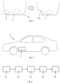
- Fig. 4 shows a representation of adding the 3D shape of the detected object 3 to the projection surface 15.
- a vehicle 2 and the projection surface 15 of the surround view system are shown.
- the Fig. 4 another object 3, here another vehicle.
- This additional object 3 can be detected by the surround view system and the 3D shape of the detected object can be determined by the surround view system, e.g. directly via sensors or indirectly by comparing it with a database and predefined 3D shapes for certain objects.
- the 3D shape of the detected object was added to the projection surface 15, creating an adapted projection surface 16. This allows the captured environmental data to be projected onto the projection surface more realistically.
- a hidden area may be present in the adapted projection surface 16 for which no explicit environmental data exists, since the object itself covers this area.
- the adapted Projection surface 16 can be moved in various ways. Unlike in the claimed invention, these can be filled with a predefined color or a predefined pattern, e.g., black. This hidden area can be filled by interpolating the surrounding environmental data.
- the front of the detected object can also be projected onto its back (hidden area).
- Fig. 5 shows a vehicle 2 with a surround view system 1 as described above and below.
- the described surround view system provides the driver of vehicle 2 with an improved display of the captured environmental data, with the perspective of the display being able to be changed or adjusted according to the driver's wishes.
- an adapted projection surface By using an adapted projection surface, distortions caused by raised objects can be reduced or avoided.
- Fig. 6 shows a flowchart for a method for adapting a projection surface for a surround view system.
- step S1 environmental data is acquired by a detection unit.
- step S2 an object can be detected in this environmental data.
- step S3 the 3D shape of the object detected in step S2 is determined.
- the 3D shape of the object can be detected directly by the detection unit or calculated by the evaluation unit, or the evaluation unit can access predefined 3D shapes and select the appropriate one based on the acquired environmental data.
- the determined 3D shape of the object is added to the projection surface of the surround view system.
- step S5 the Environmental data of the recording unit is projected onto the adapted projection surface.
Landscapes
- Engineering & Computer Science (AREA)
- Physics & Mathematics (AREA)
- General Physics & Mathematics (AREA)
- Multimedia (AREA)
- Theoretical Computer Science (AREA)
- Length Measuring Devices By Optical Means (AREA)
- Image Processing (AREA)
- Traffic Control Systems (AREA)
- Devices For Indicating Variable Information By Combining Individual Elements (AREA)
- Image Analysis (AREA)
- Closed-Circuit Television Systems (AREA)
Applications Claiming Priority (2)
| Application Number | Priority Date | Filing Date | Title |
|---|---|---|---|
| DE102018203590.3A DE102018203590A1 (de) | 2018-03-09 | 2018-03-09 | Surroundview-System mit angepasster Projektionsfläche |
| PCT/DE2019/200018 WO2019170202A1 (de) | 2018-03-09 | 2019-02-26 | Surroundview-system mit angepasster projektionsfläche |
Publications (2)
| Publication Number | Publication Date |
|---|---|
| EP3762857A1 EP3762857A1 (de) | 2021-01-13 |
| EP3762857B1 true EP3762857B1 (de) | 2025-04-09 |
Family
ID=65717688
Family Applications (1)
| Application Number | Title | Priority Date | Filing Date |
|---|---|---|---|
| EP19709621.7A Active EP3762857B1 (de) | 2018-03-09 | 2019-02-26 | Surroundview-system mit angepasster projektionsfläche |
Country Status (7)
| Country | Link |
|---|---|
| US (1) | US11410430B2 (https=) |
| EP (1) | EP3762857B1 (https=) |
| JP (1) | JP7295123B2 (https=) |
| KR (1) | KR102731753B1 (https=) |
| CN (1) | CN111819571B (https=) |
| DE (1) | DE102018203590A1 (https=) |
| WO (1) | WO2019170202A1 (https=) |
Families Citing this family (13)
| Publication number | Priority date | Publication date | Assignee | Title |
|---|---|---|---|---|
| US11507789B2 (en) * | 2019-05-31 | 2022-11-22 | Lg Electronics Inc. | Electronic device for vehicle and method of operating electronic device for vehicle |
| WO2021192327A1 (ja) * | 2020-03-25 | 2021-09-30 | 三菱マテリアル株式会社 | 表面被覆切削工具 |
| CN111862210B (zh) * | 2020-06-29 | 2023-05-12 | 辽宁石油化工大学 | 一种基于环视相机的目标物检测定位方法及装置 |
| DE102021208235A1 (de) * | 2021-07-29 | 2023-02-02 | Continental Autonomous Mobility Germany GmbH | Verfahren für ein Kamerasystem sowie Kamerasystem |
| EP4310768B1 (en) * | 2022-07-18 | 2024-06-12 | Harman International Industries, Incorporated | Driver assistance system |
| KR102583959B1 (ko) * | 2022-09-02 | 2023-09-27 | 주식회사 리트빅 | 3d 뷰 시점에 따른 경계선 합성영역 제어를 통한 3d svm 영상 왜곡보정 방법 |
| DE102022125774A1 (de) * | 2022-10-06 | 2024-04-11 | Connaught Electronics Ltd. | Anzeigen von Bilddaten in einem Fahrzeug mit sich verändernder Projektionsfläche |
| KR102778519B1 (ko) | 2023-01-11 | 2025-03-11 | 주식회사 아비커스 | 선박용 svm 영상 생성 방법 및 장치 |
| CN116363631B (zh) * | 2023-05-19 | 2023-09-05 | 小米汽车科技有限公司 | 三维目标检测方法、装置及车辆 |
| DE102023207634A1 (de) | 2023-08-09 | 2025-02-13 | Continental Autonomous Mobility Germany GmbH | Verfahren zum Erzeugen einer eine Fahrzeugumgebung darstellenden Umgebungsdarstellung, Steuereinrichtung, Fahrerassistenzsystem und Fahrzeug |
| DE102023207633A1 (de) | 2023-08-09 | 2025-02-13 | Continental Autonomous Mobility Germany GmbH | Verfahren zum Erzeugen einer eine Fahrzeugumgebung darstellenden Umgebungsdarstellung, Steuereinrichtung, Fahrerassistenzsystem und Fahrzeug |
| DE102023208357A1 (de) | 2023-08-31 | 2025-03-06 | Continental Autonomous Mobility Germany GmbH | Verfahren zur Erzeugung einer Umgebungsansicht eines Fahrzeugs |
| KR102689115B1 (ko) * | 2023-10-13 | 2024-07-26 | 주식회사 리트빅 | 엣지 클라우드 환경의 딥러닝 기반 가변형 3d 어라운드뷰 모니터링 시스템 |
Family Cites Families (47)
| Publication number | Priority date | Publication date | Assignee | Title |
|---|---|---|---|---|
| US5644689A (en) * | 1992-01-13 | 1997-07-01 | Hitachi, Ltd. | Arbitrary viewpoint three-dimensional imaging method using compressed voxel data constructed by a directed search of voxel data representing an image of an object and an arbitrary viewpoint |
| JP4195966B2 (ja) | 2002-03-05 | 2008-12-17 | パナソニック株式会社 | 画像表示制御装置 |
| JP3871614B2 (ja) | 2002-06-12 | 2007-01-24 | 松下電器産業株式会社 | 運転支援装置 |
| JP2004240480A (ja) * | 2003-02-03 | 2004-08-26 | Matsushita Electric Ind Co Ltd | 運転支援装置 |
| FR2853121B1 (fr) * | 2003-03-25 | 2006-12-15 | Imra Europe Sa | Dispositif de surveillance des alentours d'un vehicule |
| JPWO2006109398A1 (ja) * | 2005-03-15 | 2008-10-09 | オムロン株式会社 | 画像処理装置および方法、プログラム、並びに記録媒体 |
| JP4180065B2 (ja) * | 2005-05-13 | 2008-11-12 | 株式会社スクウェア・エニックス | 画像生成方法、画像生成装置、および画像生成プログラム |
| JP4642723B2 (ja) | 2006-09-26 | 2011-03-02 | クラリオン株式会社 | 画像生成装置および画像生成方法 |
| CN101246545B (zh) * | 2008-02-22 | 2010-07-07 | 华南师范大学 | 一种光学遥感图像去云的泊松方法 |
| DE102008060684B4 (de) * | 2008-03-28 | 2019-05-23 | Volkswagen Ag | Verfahren und Vorrichtung zum automatischen Einparken eines Kraftfahrzeugs |
| EP2285109B1 (en) | 2008-05-29 | 2018-11-28 | Fujitsu Limited | Vehicle image processor, and vehicle image processing system |
| CN102239506B (zh) | 2008-10-02 | 2014-07-09 | 弗兰霍菲尔运输应用研究公司 | 中间视合成和多视点数据信号的提取 |
| JP5165631B2 (ja) * | 2009-04-14 | 2013-03-21 | 現代自動車株式会社 | 車両周囲画像表示システム |
| JP5223811B2 (ja) | 2009-08-06 | 2013-06-26 | 株式会社日本自動車部品総合研究所 | 画像補正装置、画像補正方法、及びそれらに用いられる変換マップ作成方法 |
| JP5682284B2 (ja) * | 2010-12-16 | 2015-03-11 | 株式会社島津製作所 | X線撮影装置 |
| JP2012244600A (ja) | 2011-05-24 | 2012-12-10 | Fujitsu Ten Ltd | 画像表示システム、画像処理装置、及び、画像表示方法 |
| WO2013016409A1 (en) | 2011-07-26 | 2013-01-31 | Magna Electronics Inc. | Vision system for vehicle |
| DE102011084554A1 (de) | 2011-10-14 | 2013-04-18 | Robert Bosch Gmbh | Verfahren zur Darstellung eines Fahrzeugumfeldes |
| DE102012018325A1 (de) * | 2012-09-15 | 2014-03-20 | DSP-Weuffen GmbH | Verfahren und Vorrichtung für ein bildgebendes Fahrerassistenzsystem mit adaptiver Umsichtdarstellung |
| US9225942B2 (en) | 2012-10-11 | 2015-12-29 | GM Global Technology Operations LLC | Imaging surface modeling for camera modeling and virtual view synthesis |
| US20140114534A1 (en) | 2012-10-19 | 2014-04-24 | GM Global Technology Operations LLC | Dynamic rearview mirror display features |
| US8892358B2 (en) * | 2013-03-14 | 2014-11-18 | Robert Bosch Gmbh | System and method for distortion correction in three-dimensional environment visualization |
| US9834143B2 (en) | 2013-05-23 | 2017-12-05 | GM Global Technology Operations LLC | Enhanced perspective view generation in a front curb viewing system |
| US9886636B2 (en) | 2013-05-23 | 2018-02-06 | GM Global Technology Operations LLC | Enhanced top-down view generation in a front curb viewing system |
| US20150042799A1 (en) | 2013-08-07 | 2015-02-12 | GM Global Technology Operations LLC | Object highlighting and sensing in vehicle image display systems |
| US9013286B2 (en) * | 2013-09-23 | 2015-04-21 | Volkswagen Ag | Driver assistance system for displaying surroundings of a vehicle |
| TWI528325B (zh) | 2013-10-18 | 2016-04-01 | 財團法人資訊工業策進會 | 影像處理方法及應用影像處理方法之系統 |
| KR101470230B1 (ko) * | 2013-10-30 | 2014-12-08 | 현대자동차주식회사 | 주차 영역 추적 장치 및 그 방법 |
| EP3085074B1 (en) | 2013-12-19 | 2020-02-26 | Intel Corporation | Bowl-shaped imaging system |
| KR20150076759A (ko) | 2013-12-27 | 2015-07-07 | 주식회사 만도 | 차량용 카메라의 제어 장치 및 방법 |
| DE102014000495A1 (de) * | 2014-01-14 | 2014-08-14 | Daimler Ag | Vorrichtung und Verfahren zur Projektion von Informationen in emer Fahrzeugumgebung und Fahrzeug |
| DE102014208664A1 (de) * | 2014-05-08 | 2015-11-12 | Conti Temic Microelectronic Gmbh | Verfahren und vorrichtung zum verzerrungsfreien anzeigen einer fahrzeugumgebung eines fahrzeuges |
| US10442355B2 (en) | 2014-09-17 | 2019-10-15 | Intel Corporation | Object visualization in bowl-shaped imaging systems |
| US9437001B2 (en) | 2014-09-18 | 2016-09-06 | Intel Corporation | Tracking objects in bowl-shaped imaging systems |
| DE102015202863A1 (de) * | 2015-02-17 | 2016-08-18 | Conti Temic Microelectronic Gmbh | Verfahren und Vorrichtung zum verzerrungsfreien Anzeigen einer Fahrzeugumgebung eines Fahrzeuges |
| DE102015206477A1 (de) | 2015-04-10 | 2016-10-13 | Robert Bosch Gmbh | Verfahren zur Darstellung einer Fahrzeugumgebung eines Fahrzeuges |
| DE102015208343B4 (de) | 2015-05-06 | 2023-09-07 | Robert Bosch Gmbh | Verfahren zum Erzeugen eines Gesamtbildes einer Fahrzeugumgebung eines Fahrzeuges und entsprechende Vorrichtung |
| DE102015214611A1 (de) * | 2015-07-31 | 2017-02-02 | Conti Temic Microelectronic Gmbh | Verfahren und Vorrichtung zum Anzeigen einer Umgebungsszene eines Fahrzeuggespanns |
| DE102015223176A1 (de) | 2015-11-24 | 2017-05-24 | Conti Temic Microelectronic Gmbh | Verfahren und Vorrichtung zur Ermittlung von Verdeckungsbereichen in der Fahrzeugumgebung eines Fahrzeuges |
| DE102016211227A1 (de) | 2016-06-23 | 2017-12-28 | Conti Temic Microelectronic Gmbh | Verfahren und Fahrzeugsteuersystem zum Erzeugen von Abbildungen eines Umfeldmodells und entsprechendes Fahrzeug |
| DE102016211453A1 (de) | 2016-06-27 | 2017-12-28 | Conti Temic Microelectronic Gmbh | Verfahren und Fahrzeugsteuersystem zum Erzeugen von Abbildungen eines Umfeldmodells und entsprechendes Fahrzeug |
| JP6611353B2 (ja) * | 2016-08-01 | 2019-11-27 | クラリオン株式会社 | 画像処理装置、外界認識装置 |
| JP6659495B2 (ja) * | 2016-08-19 | 2020-03-04 | 株式会社東芝 | 撮像装置および送信方法 |
| DE102016220651A1 (de) | 2016-10-20 | 2018-04-26 | Conti Temic Microelectronic Gmbh | Verfahren und Vorrichtung zur Erzeugung einer Fahrzeugumgebungsansicht bei einem Fahrzeug |
| DE102016223391A1 (de) | 2016-11-25 | 2018-05-30 | Conti Temic Microelectronic Gmbh | Verfahren und vorrichtung zum erzeugen einer fahrzeugumgebungsansicht bei einem fahrzeug |
| DE102016225066A1 (de) | 2016-12-15 | 2018-06-21 | Conti Temic Microelectronic Gmbh | Rundumsichtsystem für ein Fahrzeug |
| DE102017206175A1 (de) | 2017-04-11 | 2018-10-11 | Conti Temic Microelectronic Gmbh | Surround-View-System für ein Fahrzeug |
-
2018
- 2018-03-09 DE DE102018203590.3A patent/DE102018203590A1/de not_active Withdrawn
-
2019
- 2019-02-26 KR KR1020207023212A patent/KR102731753B1/ko active Active
- 2019-02-26 CN CN201980017717.8A patent/CN111819571B/zh active Active
- 2019-02-26 EP EP19709621.7A patent/EP3762857B1/de active Active
- 2019-02-26 JP JP2020544254A patent/JP7295123B2/ja active Active
- 2019-02-26 US US16/979,308 patent/US11410430B2/en active Active
- 2019-02-26 WO PCT/DE2019/200018 patent/WO2019170202A1/de not_active Ceased
Also Published As
| Publication number | Publication date |
|---|---|
| US11410430B2 (en) | 2022-08-09 |
| EP3762857A1 (de) | 2021-01-13 |
| CN111819571A (zh) | 2020-10-23 |
| KR20200126365A (ko) | 2020-11-06 |
| US20210004614A1 (en) | 2021-01-07 |
| KR102731753B1 (ko) | 2024-11-20 |
| DE102018203590A1 (de) | 2019-09-12 |
| WO2019170202A1 (de) | 2019-09-12 |
| JP7295123B2 (ja) | 2023-06-20 |
| JP2021516390A (ja) | 2021-07-01 |
| CN111819571B (zh) | 2024-09-06 |
Similar Documents
| Publication | Publication Date | Title |
|---|---|---|
| EP3762857B1 (de) | Surroundview-system mit angepasster projektionsfläche | |
| DE102014107158B4 (de) | Verbesserte Top-Down-Bilderzeugung in einem Frontbordstein-Visualisierungssystem | |
| DE102014107156B4 (de) | System und Verfahren zum Bereitstellen einer verbesserten perspektivischen Bilderzeugung in einem Frontbordstein-Visualisierungssystem | |
| DE102014107155B4 (de) | Verbessertes Frontbordstein-Visualisierungssystem | |
| DE102014222617B4 (de) | Fahrzeugerfassungsverfahren und Fahrzeugerfassungssytem | |
| EP3328686A1 (de) | Verfahren und vorrichtung zum anzeigen einer umgebungsszene eines fahrzeuggespanns | |
| EP3537384A2 (de) | Visuelles surround-view-system zur überwachung des fahrzeuginneren | |
| DE102012223373A1 (de) | Vorrichtung und Verfahren zum Korrigieren einer Bildverzerrung von einer Heckkamera | |
| EP3308361B1 (de) | Verfahren zur erzeugung eines virtuellen bildes einer fahrzeugumgebung | |
| DE102016104730A1 (de) | Verfahren zum Detektieren eines Objekts entlang einer Straße eines Kraftfahrzeugs, Rechenvorrichtung, Fahrerassistenzsystem sowie Kraftfahrzeug | |
| DE102018001969A1 (de) | Verfahren zur Kalibrierung eines kontaktanalogen Headup-Displays eines Fahrzeuges in einer Werkstatt | |
| DE102015202863A1 (de) | Verfahren und Vorrichtung zum verzerrungsfreien Anzeigen einer Fahrzeugumgebung eines Fahrzeuges | |
| EP3924932A1 (de) | Modulares inpainting verfahren | |
| WO2017198429A1 (de) | Ermittlung von fahrzeugumgebungsdaten | |
| DE102014225848B4 (de) | Vorrichtung, Verfahren und computerlesbares Medium zum Korrigieren eines Interpolationskoeffizienten für einen Stereoabgleich | |
| DE102011082881A1 (de) | Darstellung der Umgebung eines Kraftfahrzeugs in einer bestimmten Ansicht unter Verwendung räumlicher Information | |
| DE102018130229B4 (de) | Verfahren und Vorrichtung zur Objektextraktion aus eine dreidimensionale Szene darstellenden Szenenbilddaten | |
| EP4208372A1 (de) | Verfahren zum anzeigen einer umgebung eines fahrzeuges auf einer anzeigeeinrichtung, verarbeitungseinheit und fahrzeug | |
| EP3695387B1 (de) | Verfahren zur darstellung von bildern eines kamerasystems eines fahrzeugs | |
| DE102012201805A1 (de) | Vorrichtung und Verfahren zum Bestimmen eines Kompensationsparameters für ein Übersprechen bei einem mehrsichtbetriebsfähigen Anzeigegerät | |
| DE102015007245B4 (de) | Verfahren zum Betreiben einer Datenbrilleneinrichtung und Datenbrilleneinrichtung | |
| DE102022112317B4 (de) | Verfahren zur Ermittlung einer dreidimensionalen Ausdehnungsinformation eines Zielobjekts, Kraftfahrzeug, Computerprogramm und elektronisch lesbarer Datenträger | |
| DE102016124989A1 (de) | Bordsteinrepräsentation mit einem dreidimensionalen Körper in einem Fahrerassistenzsystem für ein Kraftfahrzeug | |
| DE102022205393A1 (de) | Verfahren zum Betreiben eines Informationssystems, Computerprogrammprodukt sowie Fahrzeug | |
| WO2017092734A2 (de) | Verfahren zur darstellung einer simulationsumgebung |
Legal Events
| Date | Code | Title | Description |
|---|---|---|---|
| STAA | Information on the status of an ep patent application or granted ep patent |
Free format text: STATUS: UNKNOWN |
|
| STAA | Information on the status of an ep patent application or granted ep patent |
Free format text: STATUS: THE INTERNATIONAL PUBLICATION HAS BEEN MADE |
|
| PUAI | Public reference made under article 153(3) epc to a published international application that has entered the european phase |
Free format text: ORIGINAL CODE: 0009012 |
|
| STAA | Information on the status of an ep patent application or granted ep patent |
Free format text: STATUS: REQUEST FOR EXAMINATION WAS MADE |
|
| 17P | Request for examination filed |
Effective date: 20201009 |
|
| AK | Designated contracting states |
Kind code of ref document: A1 Designated state(s): AL AT BE BG CH CY CZ DE DK EE ES FI FR GB GR HR HU IE IS IT LI LT LU LV MC MK MT NL NO PL PT RO RS SE SI SK SM TR |
|
| AX | Request for extension of the european patent |
Extension state: BA ME |
|
| DAV | Request for validation of the european patent (deleted) | ||
| DAX | Request for extension of the european patent (deleted) | ||
| RAP1 | Party data changed (applicant data changed or rights of an application transferred) |
Owner name: CONTINENTAL AUTONOMOUS MOBILITY GERMANY GMBH |
|
| STAA | Information on the status of an ep patent application or granted ep patent |
Free format text: STATUS: EXAMINATION IS IN PROGRESS |
|
| 17Q | First examination report despatched |
Effective date: 20221117 |
|
| REG | Reference to a national code |
Ref country code: DE Ref legal event code: R079 Free format text: PREVIOUS MAIN CLASS: G06K0009000000 Ipc: G06V0020580000 Ref document number: 502019013177 Country of ref document: DE |
|
| GRAP | Despatch of communication of intention to grant a patent |
Free format text: ORIGINAL CODE: EPIDOSNIGR1 |
|
| STAA | Information on the status of an ep patent application or granted ep patent |
Free format text: STATUS: GRANT OF PATENT IS INTENDED |
|
| RIC1 | Information provided on ipc code assigned before grant |
Ipc: G06V 20/64 20220101ALI20241101BHEP Ipc: G06V 20/58 20220101AFI20241101BHEP |
|
| INTG | Intention to grant announced |
Effective date: 20241118 |
|
| GRAS | Grant fee paid |
Free format text: ORIGINAL CODE: EPIDOSNIGR3 |
|
| GRAA | (expected) grant |
Free format text: ORIGINAL CODE: 0009210 |
|
| STAA | Information on the status of an ep patent application or granted ep patent |
Free format text: STATUS: THE PATENT HAS BEEN GRANTED |
|
| AK | Designated contracting states |
Kind code of ref document: B1 Designated state(s): AL AT BE BG CH CY CZ DE DK EE ES FI FR GB GR HR HU IE IS IT LI LT LU LV MC MK MT NL NO PL PT RO RS SE SI SK SM TR |
|
| REG | Reference to a national code |
Ref country code: GB Ref legal event code: FG4D Free format text: NOT ENGLISH |
|
| REG | Reference to a national code |
Ref country code: CH Ref legal event code: EP |
|
| REG | Reference to a national code |
Ref country code: DE Ref legal event code: R096 Ref document number: 502019013177 Country of ref document: DE |
|
| REG | Reference to a national code |
Ref country code: IE Ref legal event code: FG4D Free format text: LANGUAGE OF EP DOCUMENT: GERMAN |
|
| REG | Reference to a national code |
Ref country code: DE Ref legal event code: R081 Ref document number: 502019013177 Country of ref document: DE Owner name: AUMOVIO AUTONOMOUS MOBILITY GERMANY GMBH, DE Free format text: FORMER OWNER: CONTINENTAL AUTONOMOUS MOBILITY GERMANY GMBH, 85057 INGOLSTADT, DE |
|
| RAP4 | Party data changed (patent owner data changed or rights of a patent transferred) |
Owner name: AUMOVIO AUTONOMOUS MOBILITY GERMANY GMBH |
|
| REG | Reference to a national code |
Ref country code: NL Ref legal event code: MP Effective date: 20250409 |
|
| PG25 | Lapsed in a contracting state [announced via postgrant information from national office to epo] |
Ref country code: NL Free format text: LAPSE BECAUSE OF FAILURE TO SUBMIT A TRANSLATION OF THE DESCRIPTION OR TO PAY THE FEE WITHIN THE PRESCRIBED TIME-LIMIT Effective date: 20250409 |
|
| PG25 | Lapsed in a contracting state [announced via postgrant information from national office to epo] |
Ref country code: PT Free format text: LAPSE BECAUSE OF FAILURE TO SUBMIT A TRANSLATION OF THE DESCRIPTION OR TO PAY THE FEE WITHIN THE PRESCRIBED TIME-LIMIT Effective date: 20250811 Ref country code: FI Free format text: LAPSE BECAUSE OF FAILURE TO SUBMIT A TRANSLATION OF THE DESCRIPTION OR TO PAY THE FEE WITHIN THE PRESCRIBED TIME-LIMIT Effective date: 20250409 Ref country code: ES Free format text: LAPSE BECAUSE OF FAILURE TO SUBMIT A TRANSLATION OF THE DESCRIPTION OR TO PAY THE FEE WITHIN THE PRESCRIBED TIME-LIMIT Effective date: 20250409 |
|
| REG | Reference to a national code |
Ref country code: LT Ref legal event code: MG9D |
|
| PG25 | Lapsed in a contracting state [announced via postgrant information from national office to epo] |
Ref country code: NO Free format text: LAPSE BECAUSE OF FAILURE TO SUBMIT A TRANSLATION OF THE DESCRIPTION OR TO PAY THE FEE WITHIN THE PRESCRIBED TIME-LIMIT Effective date: 20250709 Ref country code: GR Free format text: LAPSE BECAUSE OF FAILURE TO SUBMIT A TRANSLATION OF THE DESCRIPTION OR TO PAY THE FEE WITHIN THE PRESCRIBED TIME-LIMIT Effective date: 20250710 |
|
| PG25 | Lapsed in a contracting state [announced via postgrant information from national office to epo] |
Ref country code: PL Free format text: LAPSE BECAUSE OF FAILURE TO SUBMIT A TRANSLATION OF THE DESCRIPTION OR TO PAY THE FEE WITHIN THE PRESCRIBED TIME-LIMIT Effective date: 20250409 |
|
| PG25 | Lapsed in a contracting state [announced via postgrant information from national office to epo] |
Ref country code: BG Free format text: LAPSE BECAUSE OF FAILURE TO SUBMIT A TRANSLATION OF THE DESCRIPTION OR TO PAY THE FEE WITHIN THE PRESCRIBED TIME-LIMIT Effective date: 20250409 |
|
| PG25 | Lapsed in a contracting state [announced via postgrant information from national office to epo] |
Ref country code: HR Free format text: LAPSE BECAUSE OF FAILURE TO SUBMIT A TRANSLATION OF THE DESCRIPTION OR TO PAY THE FEE WITHIN THE PRESCRIBED TIME-LIMIT Effective date: 20250409 |
|
| PG25 | Lapsed in a contracting state [announced via postgrant information from national office to epo] |
Ref country code: RS Free format text: LAPSE BECAUSE OF FAILURE TO SUBMIT A TRANSLATION OF THE DESCRIPTION OR TO PAY THE FEE WITHIN THE PRESCRIBED TIME-LIMIT Effective date: 20250709 |
|
| PG25 | Lapsed in a contracting state [announced via postgrant information from national office to epo] |
Ref country code: IS Free format text: LAPSE BECAUSE OF FAILURE TO SUBMIT A TRANSLATION OF THE DESCRIPTION OR TO PAY THE FEE WITHIN THE PRESCRIBED TIME-LIMIT Effective date: 20250809 |
|
| PG25 | Lapsed in a contracting state [announced via postgrant information from national office to epo] |
Ref country code: LV Free format text: LAPSE BECAUSE OF FAILURE TO SUBMIT A TRANSLATION OF THE DESCRIPTION OR TO PAY THE FEE WITHIN THE PRESCRIBED TIME-LIMIT Effective date: 20250409 |
|
| REG | Reference to a national code |
Ref country code: DE Ref legal event code: R097 Ref document number: 502019013177 Country of ref document: DE |
|
| PG25 | Lapsed in a contracting state [announced via postgrant information from national office to epo] |
Ref country code: SM Free format text: LAPSE BECAUSE OF FAILURE TO SUBMIT A TRANSLATION OF THE DESCRIPTION OR TO PAY THE FEE WITHIN THE PRESCRIBED TIME-LIMIT Effective date: 20250409 Ref country code: DK Free format text: LAPSE BECAUSE OF FAILURE TO SUBMIT A TRANSLATION OF THE DESCRIPTION OR TO PAY THE FEE WITHIN THE PRESCRIBED TIME-LIMIT Effective date: 20250409 |
|
| PG25 | Lapsed in a contracting state [announced via postgrant information from national office to epo] |
Ref country code: CZ Free format text: LAPSE BECAUSE OF FAILURE TO SUBMIT A TRANSLATION OF THE DESCRIPTION OR TO PAY THE FEE WITHIN THE PRESCRIBED TIME-LIMIT Effective date: 20250409 |
|
| PG25 | Lapsed in a contracting state [announced via postgrant information from national office to epo] |
Ref country code: EE Free format text: LAPSE BECAUSE OF FAILURE TO SUBMIT A TRANSLATION OF THE DESCRIPTION OR TO PAY THE FEE WITHIN THE PRESCRIBED TIME-LIMIT Effective date: 20250409 |
|
| PG25 | Lapsed in a contracting state [announced via postgrant information from national office to epo] |
Ref country code: SK Free format text: LAPSE BECAUSE OF FAILURE TO SUBMIT A TRANSLATION OF THE DESCRIPTION OR TO PAY THE FEE WITHIN THE PRESCRIBED TIME-LIMIT Effective date: 20250409 Ref country code: RO Free format text: LAPSE BECAUSE OF FAILURE TO SUBMIT A TRANSLATION OF THE DESCRIPTION OR TO PAY THE FEE WITHIN THE PRESCRIBED TIME-LIMIT Effective date: 20250409 |
|
| PG25 | Lapsed in a contracting state [announced via postgrant information from national office to epo] |
Ref country code: IT Free format text: LAPSE BECAUSE OF FAILURE TO SUBMIT A TRANSLATION OF THE DESCRIPTION OR TO PAY THE FEE WITHIN THE PRESCRIBED TIME-LIMIT Effective date: 20250409 |
|
| PLBE | No opposition filed within time limit |
Free format text: ORIGINAL CODE: 0009261 |
|
| STAA | Information on the status of an ep patent application or granted ep patent |
Free format text: STATUS: NO OPPOSITION FILED WITHIN TIME LIMIT |
|
| REG | Reference to a national code |
Ref country code: CH Ref legal event code: L10 Free format text: ST27 STATUS EVENT CODE: U-0-0-L10-L00 (AS PROVIDED BY THE NATIONAL OFFICE) Effective date: 20260218 |
|
| 26N | No opposition filed |
Effective date: 20260112 |
|
| PGFP | Annual fee paid to national office [announced via postgrant information from national office to epo] |
Ref country code: GB Payment date: 20260223 Year of fee payment: 8 |
|
| PGFP | Annual fee paid to national office [announced via postgrant information from national office to epo] |
Ref country code: DE Payment date: 20260228 Year of fee payment: 8 |
|
| PGFP | Annual fee paid to national office [announced via postgrant information from national office to epo] |
Ref country code: FR Payment date: 20260227 Year of fee payment: 8 |