EP3761920B1 - Orthese mit anschlagstifthalter - Google Patents
Orthese mit anschlagstifthalter Download PDFInfo
- Publication number
- EP3761920B1 EP3761920B1 EP19710372.4A EP19710372A EP3761920B1 EP 3761920 B1 EP3761920 B1 EP 3761920B1 EP 19710372 A EP19710372 A EP 19710372A EP 3761920 B1 EP3761920 B1 EP 3761920B1
- Authority
- EP
- European Patent Office
- Prior art keywords
- stop pin
- arm
- orthosis
- holding arm
- orthosis according
- Prior art date
- Legal status (The legal status is an assumption and is not a legal conclusion. Google has not performed a legal analysis and makes no representation as to the accuracy of the status listed.)
- Active
Links
Images

Classifications
-
- A—HUMAN NECESSITIES
- A61—MEDICAL OR VETERINARY SCIENCE; HYGIENE
- A61F—FILTERS IMPLANTABLE INTO BLOOD VESSELS; PROSTHESES; DEVICES PROVIDING PATENCY TO, OR PREVENTING COLLAPSING OF, TUBULAR STRUCTURES OF THE BODY, e.g. STENTS; ORTHOPAEDIC, NURSING OR CONTRACEPTIVE DEVICES; FOMENTATION; TREATMENT OR PROTECTION OF EYES OR EARS; BANDAGES, DRESSINGS OR ABSORBENT PADS; FIRST-AID KITS
- A61F5/00—Orthopaedic methods or devices for non-surgical treatment of bones or joints; Nursing devices ; Anti-rape devices
- A61F5/01—Orthopaedic devices, e.g. long-term immobilising or pressure directing devices for treating broken or deformed bones such as splints, casts or braces
- A61F5/0102—Orthopaedic devices, e.g. long-term immobilising or pressure directing devices for treating broken or deformed bones such as splints, casts or braces specially adapted for correcting deformities of the limbs or for supporting them; Ortheses, e.g. with articulations
- A61F5/0123—Orthopaedic devices, e.g. long-term immobilising or pressure directing devices for treating broken or deformed bones such as splints, casts or braces specially adapted for correcting deformities of the limbs or for supporting them; Ortheses, e.g. with articulations for the knees
- A61F5/0125—Orthopaedic devices, e.g. long-term immobilising or pressure directing devices for treating broken or deformed bones such as splints, casts or braces specially adapted for correcting deformities of the limbs or for supporting them; Ortheses, e.g. with articulations for the knees the device articulating around a single pivot-point
-
- A—HUMAN NECESSITIES
- A61—MEDICAL OR VETERINARY SCIENCE; HYGIENE
- A61F—FILTERS IMPLANTABLE INTO BLOOD VESSELS; PROSTHESES; DEVICES PROVIDING PATENCY TO, OR PREVENTING COLLAPSING OF, TUBULAR STRUCTURES OF THE BODY, e.g. STENTS; ORTHOPAEDIC, NURSING OR CONTRACEPTIVE DEVICES; FOMENTATION; TREATMENT OR PROTECTION OF EYES OR EARS; BANDAGES, DRESSINGS OR ABSORBENT PADS; FIRST-AID KITS
- A61F5/00—Orthopaedic methods or devices for non-surgical treatment of bones or joints; Nursing devices ; Anti-rape devices
- A61F5/01—Orthopaedic devices, e.g. long-term immobilising or pressure directing devices for treating broken or deformed bones such as splints, casts or braces
- A61F5/0102—Orthopaedic devices, e.g. long-term immobilising or pressure directing devices for treating broken or deformed bones such as splints, casts or braces specially adapted for correcting deformities of the limbs or for supporting them; Ortheses, e.g. with articulations
- A61F5/013—Orthopaedic devices, e.g. long-term immobilising or pressure directing devices for treating broken or deformed bones such as splints, casts or braces specially adapted for correcting deformities of the limbs or for supporting them; Ortheses, e.g. with articulations for the arms, hands or fingers
-
- A—HUMAN NECESSITIES
- A61—MEDICAL OR VETERINARY SCIENCE; HYGIENE
- A61F—FILTERS IMPLANTABLE INTO BLOOD VESSELS; PROSTHESES; DEVICES PROVIDING PATENCY TO, OR PREVENTING COLLAPSING OF, TUBULAR STRUCTURES OF THE BODY, e.g. STENTS; ORTHOPAEDIC, NURSING OR CONTRACEPTIVE DEVICES; FOMENTATION; TREATMENT OR PROTECTION OF EYES OR EARS; BANDAGES, DRESSINGS OR ABSORBENT PADS; FIRST-AID KITS
- A61F5/00—Orthopaedic methods or devices for non-surgical treatment of bones or joints; Nursing devices ; Anti-rape devices
- A61F5/01—Orthopaedic devices, e.g. long-term immobilising or pressure directing devices for treating broken or deformed bones such as splints, casts or braces
- A61F5/0102—Orthopaedic devices, e.g. long-term immobilising or pressure directing devices for treating broken or deformed bones such as splints, casts or braces specially adapted for correcting deformities of the limbs or for supporting them; Ortheses, e.g. with articulations
- A61F2005/0132—Additional features of the articulation
- A61F2005/0165—Additional features of the articulation with limits of movement
- A61F2005/0167—Additional features of the articulation with limits of movement adjustable
-
- A—HUMAN NECESSITIES
- A61—MEDICAL OR VETERINARY SCIENCE; HYGIENE
- A61F—FILTERS IMPLANTABLE INTO BLOOD VESSELS; PROSTHESES; DEVICES PROVIDING PATENCY TO, OR PREVENTING COLLAPSING OF, TUBULAR STRUCTURES OF THE BODY, e.g. STENTS; ORTHOPAEDIC, NURSING OR CONTRACEPTIVE DEVICES; FOMENTATION; TREATMENT OR PROTECTION OF EYES OR EARS; BANDAGES, DRESSINGS OR ABSORBENT PADS; FIRST-AID KITS
- A61F5/00—Orthopaedic methods or devices for non-surgical treatment of bones or joints; Nursing devices ; Anti-rape devices
- A61F5/01—Orthopaedic devices, e.g. long-term immobilising or pressure directing devices for treating broken or deformed bones such as splints, casts or braces
- A61F5/0102—Orthopaedic devices, e.g. long-term immobilising or pressure directing devices for treating broken or deformed bones such as splints, casts or braces specially adapted for correcting deformities of the limbs or for supporting them; Ortheses, e.g. with articulations
- A61F2005/0132—Additional features of the articulation
- A61F2005/0179—Additional features of the articulation with spring means
Definitions
- Orthopedic orthoses are known to be used to guide and stabilize joints such as knee or elbow joints and/or to urge limbs in the direction of extension or flexion by means of spring force.
- the invention is therefore based on the object of creating an orthosis of the type mentioned at the outset with a pivoting range adjustment device which can be operated easily and without tools and which ensures that the pivoting range stop pins are held captive.
- the swivel range adjustment device comprises at least one flexible stop pin holder, which has a bearing section that can be rotated about an axis and a resilient holding arm, to which the stop pin is fastened.
- the orthosis according to the invention offers the advantage that the pivoting range limit(s) can be adjusted without tools and in a very simple and quick manner. It is also particularly advantageous that the stop pin is held captive on the orthosis.
- the stop pin holder is expediently designed in this way and arranged such that the stop pin can only be pulled out of one of the holes provided for limiting the pivoting range against the spring force of the stop pin holder.
- the stop pin holder can be designed in a very space-saving manner.
- the stop pin holder according to the invention is therefore particularly suitable for orthoses of small size, for example for children or small animals.
- the bearing section consists of a bearing ring which is arranged to be rotatable about the pivot axis of the orthosis. This allows the stop pin holder and thus the stop pin attached to it to be rotated very easily around the pivot axis into that angular position which is optimal for the desired positioning of the stop pin, without stresses occurring within the stop pin holder in the circumferential direction.
- the holding arm is advantageously designed in a meandering, S, U, V or W shape. As a result, a relatively large length of the holding arm can be achieved in a very small space. This provides a large range of motion for the stopper pin, facilitating removal of the stopper pin from and insertion into the swing limit holes.
- the support arm has a first arm portion which is concentric with the bearing ring in a first circumferential direction, and a second arm portion which is concentric with the bearing ring in a second circumferential direction, which is opposite to the first circumferential direction.
- the two arm sections expediently run in an arc of a circle concentrically to the pivot axis of the orthosis with only a small distance from one another. This enables the desired freedom of movement for the stop pin when changing the limit of the pivoting range in a particularly space-saving manner.
- the holding arm is advantageously designed as a leaf spring.
- a very thin sheet of spring steel with a thickness of, for example, only 0.2-0.5 mm, in particular 0.3 mm, can be used to produce the leaf spring, as a result of which the leaf spring takes up very little installation height.
- leaf springs are dimensionally stable in the direction of their main plane, while they allow simple rebounding, i.e. slight elastic bending, perpendicular to the main plane.
- Leaf springs made from a different material, for example plastic are also possible.
- the holding arm has a detachable pin attachment device in the form of a clip connection for attaching the stop pin.
- the stop pin can be attached to the stop pin holder in a simple and quick manner during assembly or can be removed from it if necessary.
- the fastening device comprises an insertion hole for inserting the stop pin and at least one spring or latching tongue which engages in a peripheral groove of the stop pin.
- a ring of spring tongues or locking tongues is provided, which extends inwards around the insertion hole and engages in a locking manner with the stop pin when it reaches the region of the circumferential groove of the stop pin.
- the bearing section and the holding arm are preferably designed as a one-piece spring sheet metal element.
- the stop holder can be produced in a particularly simple and cost-effective manner, for example by means of a stamping process.
- figure 1 shows a middle section of an orthosis according to the invention without a cover with a first rail arm 1 and a second rail arm 2, with an axis element 5 being shown in section.
- the two rail arms 1, 2 are only shown in abbreviated form and have fastening devices, not shown, in particular Velcro strips, shells or the like, with which the rail arms 1, 2 can be attached in a known manner to limbs connected by means of a body joint, for example on the thigh and lower leg, upper - and lower arm, etc., can be attached.
- the rail arms 1, 2 are connected to one another in an articulated manner in a joint region 3 and can be pivoted about a pivot axis 4 relative to one another.
- the pivot axis 4 is formed by the axis element 5, which is fixed to the first rail arm 1.
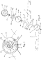
- FIG 2 shows the structure of the orthosis according to the invention in an exploded view.
- the first rail arm 1 has an end region 6 in the shape of a circular disc with a central bore 7 .
- This bore 7 serves to accommodate a cylindrical section 8 ( figure 7 ) of the axis element 5 and for the passage of a central Screw 9 which can be screwed into an axial threaded bore 10 of the axle element 5 in order to connect the axle element 5 and the first rail arm 1 in a rotationally fixed manner.
- a plurality of pivoting range limiting holes 11 are provided, which are arranged on a circular arc concentric to the pivoting axis 4 .
- the orthosis also has a first friction-reducing disc 12, the second rail arm 2, a second friction-reducing disc 13, a perforated disc 14, two stop pin holders 15a, 15b, the axle element 5 and a cover 16, one after the other in the axial direction.
- the two friction-reducing disks 12, 13 are expediently made of plastic, in particular Teflon.
- the second rail arm 2 has an end area 17 with a bore 18 .
- the bore 18 serves to accommodate a cylindrical bearing sleeve 19 which is rotatably mounted on the cylindrical section 8 of the axle element 5 so that the second rail arm 2 can be pivoted about the pivot axis 4 relative to the first rail arm 1 .
- the end region 17 of the second rail arm 2 has a circumference 20 in the shape of a circular arc over approximately 180°.
- a radially projecting stop surface 21 adjoins this arcuate circumference 20 .
- the two friction-reducing discs 12, 13 have central holes 22, 23 which serve in the same way as the bore 18 for the bearing sleeve 19 to pass through.
- the perforated disk 14 is designed as a circular disk and is arranged parallel to the end region 6 of the first rail arm 1 at such a fixed distance that the second rail arm 2 can be pivoted between them. This distance is determined by the length of the cylindrical bearing sleeve 19 which rests with one end against a diameter step 25a formed by a polygonal section 25 of the axle element 5 and with its other end against the first rail arm 1 .
- the perforated disk 14 has a central opening 24 with a polygonal contour, which is used for non-rotatably slipping onto the correspondingly designed polygonal section 25 of the axle element 5 .
- the perforated disk 14 is non-rotatably connected to the first rail arm 1 by means of a screw connection (not shown) arranged in its edge region.
- a plurality of pivoting range limiting holes 26 are provided, which are aligned with the pivoting range limiting holes 11 of the first rail arm 1 and, like these, are arranged on a circular arc concentric to the pivoting axis 4 .
- the pivoting range limiting holes 11, 26 extend along an arc of a circle over approximately 270° and can be arranged, for example, in such a way that the angular distance between adjacent pivoting range limiting holes 11, 26 is 10° in each case.
- the pivoting range limiting holes 11, 26 are used to insert two stop pins 27a, 27b to limit the pivoting range of the orthosis in the extension and flexion direction.
- the stop pins 27a, 27b have a cylindrical insertion section 46 ( figure 4 ) which can be inserted parallel to the pivot axis 4 into an aligned pair of pivot range limiting holes 11, 26 up to a radially projecting collar 47.
- the pivoting range is limited in the extension direction by the stop surface 21 of the second rail arm 2 striking one of the stop pins 27a, 27b.
- the pivoting range is limited in the direction of flexion by a stop surface 28 of the second rail arm 2 striking the other stop pin 27b, 27a.
- the stop pins 27a, 27b are each held captive on the axle element 5 by a separate stop pin holder 15a, 15b.
- the two stop pin holders 15a, 15b are of the same design, but are arranged on the axle element 5 in a mirror-inverted manner.
- the two stop pin holders 15a, 15b are expediently arranged adjacent to the orthosis in the axial direction.
- Each stop pin holder 15a, 15b consists of a flat, thin leaf spring made of spring steel sheet, the thickness of which is expediently about 0.2 to 0.5 mm, in particular 0.3 mm. Other materials and thicknesses are possible.
- each stop pin holder 15a, 15b comprises an annular bearing section 30 with a central opening 31 for the passage of a cylindrical axle section 32 of the axle element 5 ( figure 7 ), on which the stop pin holder 15a, 15b is rotatably mounted.
- the two stop pin holders 15a, 15b can thus be rotated about the pivot axis 4 independently of one another.
- a resilient, elastically flexible holding arm 33 is connected to the annular bearing section 30, at the free end of which a pin fastening device 34 is provided for fastening the stop pin 27a, 27b.
- the holding arm 33 comprises a first arm section 35 which runs concentrically to the pivot axis 4 in a first circumferential direction over an angular range of approximately 110°.
- the first arm section 35 can have other lengths and, for example, extend over an angular range of 30-180°.
- the first arm portion 35 is separated from the bearing portion 30 by a gap 36 whose width is smaller than the width of the first arm portion 35 .
- the first arm section 35 transitions into a second arm section 38 by means of a 180° arc section 37, which also runs concentrically to the pivot axis 4, but in a second direction which is opposite to the first direction.
- the width of the gap 39 between the second arm section 38 and the first arm section 35 is again smaller than the width of the arm sections 35, 38.
- the second arm section 38 in the embodiment shown extends over an angular range of approximately 45-55°.
- the length of the second arm section 38 is variable to a large extent.
- the free end 4 of the holding arm 33, on which the stop pin 27a, 27b is attached can be lifted sufficiently far perpendicularly to the main plane of the stop pin holder 15a, 15b in order to pull the stop pin 27a, 27b completely out of the swivel range limiting holes 11, 26 and in one desired swivel range limitation hole 11, 26 to be able to use.
- stop pins 27a, 27b can only be pulled out of the swivel range limiting holes 11, 26 against the spring force of the stop pin holders 15a, 15b, the stop pin holders 15a, 15b simultaneously prevent an undesirable axial displacement or a loosening of the stop pins 27a, 27b from the swivel range limiting holes 11, 26 .
- the arranged at the free end 40 of the holding arm 33 pin attachment device 34 is formed in the illustrated embodiment as a releasable attachment device in the form of a clip connection for attaching the stop pin 27a, 27b.
- the pin fastening device 34 has an insertion hole 41 for inserting the stop pin 27a, 27b and spring or latching tongues 42 which fit into a peripheral groove 43 of the stop pin 27a, 27b ( figure 4 ) engage and thereby hold the stop pin 27a, 27b both radially and axially.
- the extend Spring or latching tongues 42 inward around the entire circumference of the insertion hole 41 and can be formed by radial incisions in the spring steel sheet at the edge.
- the plate- or bowl-shaped cover 16 can be designed in such a way that its peripheral wall 44 extends over the perforated disk 14 close to the first rail arm 1 .
- a lateral recess in the peripheral wall 44 creates the necessary free space for pivoting the second rail arm 2 over a maximum pivoting range of, for example, 120-160°, in particular about 140° relative to the first rail arm 1.
- this maximum pivoting range can vary widely.
- the cover 16 can be fastened to the axle element 5, to the perforated disk 14 and/or to the first swivel arm 1 in a wide variety of ways.
- the inside of the cover 16 expediently has a flat surface 45 which is at a predetermined, relatively small distance from the perforated disk 14 and holds the bearing sections 30 of the two stop pin holders 15a, 15b adjacent to the perforated disk 14 with little play and the stop pin holders 15a, 15b in an axial direction.
Landscapes
- Health & Medical Sciences (AREA)
- Nursing (AREA)
- Orthopedic Medicine & Surgery (AREA)
- Engineering & Computer Science (AREA)
- Biomedical Technology (AREA)
- Heart & Thoracic Surgery (AREA)
- Vascular Medicine (AREA)
- Life Sciences & Earth Sciences (AREA)
- Animal Behavior & Ethology (AREA)
- General Health & Medical Sciences (AREA)
- Public Health (AREA)
- Veterinary Medicine (AREA)
- Orthopedics, Nursing, And Contraception (AREA)
- Rehabilitation Tools (AREA)
Description
- Orthopädische Orthesen werden bekannterweise dafür verwendet, Gelenke wie beispielsweise Knie- oder Ellbogengelenke zu führen und zu stabilisieren und/oder Gliedmaßen mittels Federkraft in Extensions-oder Flexionsrichtung zu drängen.
- Eine Orthese gemäß dem Oberbegriff des Anspruchs 1 ist aus der
WO 2017/050824 A1 bekannt. Bei Orthesen dieser Art sind die Schwenkbereichsgrenzen, innerhalb der die Schienenarme zwischen ihrer Extensions- und Flexionsendstellung relativ zueinander verschwenkt werden können, häufig mittels verstellbarer Anschlagstifte variabel einstellbar, die als Anschläge für den verschwenkbaren Schienenarm dienen. Üblicherweise werden diese Anschlagstifte in entsprechend angeordnete Bohrungen eingeschraubt. - Nachteilig ist bei diesen bekannten Orthesen, dass das Heraus- und Einschrauben der Anschlagstifte etwas umständlich ist und hierzu ein Werkzeug benötigt wird, das nicht immer griffbereit ist.
- Aus der
WO 95/25489 - Der Erfindung liegt daher die Aufgabe zugrunde, eine Orthese der eingangs genannten Art mit einer Schwenkbereicheinstellvorrichtung zu schaffen, die einfach und werkzeuglos betätigbar ist und ein unverlierbares Halten der Schwenkbereich-Anschlagstifte sicherstellt.
- Diese Aufgabe wird erfindungsgemäß durch eine Orthese mit den Merkmalen des Anspruchs 1 gelöst. Vorteilhafte Ausführungsformen der Erfindung sind in den weiteren Ansprüchen beschrieben.
- Erfindungsgemäß umfasst die Schwenkbereicheinstellvorrichtung mindestens einen flexiblen Anschlagstifthalter, der einen um eine Achse drehbaren Lagerabschnitt und einen federnden Haltearm aufweist, an dem der Anschlagstift befestigt ist.
- Die erfindungsgemäße Orthese bietet den Vorteil, dass die Verstellung der Schwenkbereichsgrenze(n) werkzeuglos und auf sehr einfache und schnelle Weise erfolgen kann. Besonders vorteilhaft ist ferner, dass der Anschlagstift unverlierbar an der Orthese gehalten wird. Zweckmäßigerweise ist hierbei der Anschlagstifthalter derart ausgebildet und angeordnet, dass der Anschlagstift nur gegen die Federkraft des Anschlagstifthalters aus einem der zur Begrenzung des Schwenkbereichs vorgesehenen Löcher herausgezogen werden kann. Weiterhin kann der Anschlagstifthalter auf sehr platzsparende Weise ausgebildet werden. Der erfindungsgemäße Anschlagstifthalter eignet sich daher in besonders guter Weise für Orthesen mit kleiner Baugröße, beispielsweise für Kinder oder Kleintiere.
- Gemäß einer vorteilhaften Ausführungsform besteht der Lagerabschnitt aus einem Lagerring, der um die Schwenkachse der Orthese herum drehbar angeordnet ist. Hierdurch lässt sich der Anschlagstifthalter und damit der daran befestigte Anschlagstift auf sehr einfache Weise in diejenige Winkelposition um die Schwenkachse herum drehen, die für die gewünschte Positionierung des Anschlagstifts optimal ist, ohne dass es zu Spannungen innerhalb des Anschlagstifthalters in Umfangsrichtung kommen würde.
- Vorteilhafterweise ist der Haltearm mäander-, S-, U-, V-oder W-förmig ausgebildet. Hierdurch lässt sich auf kleinstem Raum eine relativ große Länge des Haltearms erreichen. Dies schafft einen großen Bewegungsspielraum für den Anschlagstift, was das Entfernen des Anschlagstifts aus den Schwenkbereichbegrenzungslöchern und das Einsetzen in diese erleichtert.
- Vorteilhafterweise weist der Haltearm einen ersten Armabschnitt, der konzentrisch zum Lagerring in einer ersten Umfangsrichtung verläuft, und einen zweiten Armabschnitt auf, der konzentrisch zum Lagerring in einer zweiten Umfangsrichtung verläuft, die zur ersten Umfangsrichtung entgegengesetzt ist. Die beiden Armabschnitte verlaufen dabei zweckmäßigerweise mit nur geringem Abstand zueinander kreisbogenförmig konzentrisch zur Schwenkachse der Orthese. Dies ermöglicht auf besonders platzsparende Weise den gewünschten Bewegungsspielraum für den Anschlagstift beim Verändern der Schwenkbereichsgrenze.
- Vorteilhafterweise ist der Haltearm als Blattfeder ausgebildet. Zur Herstellung der Blattfeder kann ein sehr dünnes Federstahlblech mit einer Dicke von beispielsweise nur 0,2 - 0,5 mm, insbesondere 0,3 mm, verwendet werden, wodurch die Blattfeder nur sehr wenig Einbauhöhe beansprucht. Gleichzeitig sind derartige Blattfedern in Richtung ihrer Hauptebene formstabil, während sie senkrecht zur Hauptebene ein einfaches Ausfedern, d.h. ein leichtes elastisches Verbiegen, ermöglichen. Blattfedern aus einem anderen Material, beispielsweise Kunststoff, sind ebenfalls möglich.
- Gemäß einer vorteilhaften Ausführungsform weist der Haltearm eine lösbare Stiftbefestigungseinrichtung in Form einer Clipverbindung zur Befestigung des Anschlagstifts auf. Hierdurch kann der Anschlagstift bei der Montage auf einfache und schnelle Weise am Anschlagstifthalter befestigt oder bei Bedarf von diesem demontiert werden. Alternativ ist es jedoch auch möglich, den Anschlagstift auf andere Weise, insbesondere durch eine Schweiß- oder Klebeverbindung, am Haltearm zu befestigen.
- Vorteilhafterweise umfasst die Befestigungseinrichtung ein Einsteckloch zum Einstecken des Anschlagstifts und mindestens eine Feder- oder Rastzunge, die in eine Umfangsnut des Anschlagstifts eingreift. Besonders bevorzugt ist ein Federzungen- oder Rastzungenkranz vorgesehen, der sich um das Einsteckloch herum nach innen erstreckt und mit dem Anschlagstift verrastend in Eingriff tritt, wenn er in den Bereich der Umfangsnut des Anschlagstifts gelangt. Hierdurch wird der Anschlagstift auf besonders einfache und sichere Weise am Haltearm gehalten.
- Vorzugsweise sind der Lagerabschnitt und der Haltearm als einstückiges Federblechelement ausgebildet. Hierdurch lässt sich der Anschlaghalter auf besonders einfache und kostengünstige Weise, beispielsweise mittels eines Stanzvorgangs, herstellen. Alternativ ist es auch möglich, den Lagerabschnitt und den Haltearm getrennt herzustellen und nachträglich miteinander zu verbinden.
- Die Erfindung wird nachfolgend anhand der Zeichnungen beispielhaft näher erläutert. In diesen zeigen:
- Fig. 1:
- eine Darstellung des Gelenkbereichs der erfindungsgemäßen Orthese ohne Deckel, wobei das Achselement geschnitten dargestellt ist,
- Fig. 2:
- eine Explosionszeichnung der erfindungsgemäßen Orthese,
- Fig. 3
- eine Draufsicht auf einen Anschlagstifthalter,
- Fig. 4:
- eine Seitenansicht eines Anschlagstifts,
- Fig. 5:
- eine Draufsicht auf den Anschlagstift von
Fig. 4 , - Fig. 6:
- eine frontseitige Ansicht des Achselements, und
- Fig. 7:
- einen Längsschnitt durch das Achselement von
Figur 6 . -
Figur 1 zeigt einen mittleren Abschnitt einer erfindungsgemäßen Orthese ohne Deckel mit einem ersten Schienenarm 1 und einem zweiten Schienenarm 2, wobei ein Achselement 5 geschnitten dargestellt ist. Die beiden Schienenarme 1, 2 sind lediglich verkürzt dargestellt und weisen nicht dargestellte Befestigungseinrichtungen, insbesondere Klettbänder, Schalen oder dergleichen, auf, mit denen die Schienenarme 1, 2 in bekannter Weise an mittels eines Körpergelenks verbundenen Gliedmaßen, beispielsweise am Ober- und Unterschenkel, Ober- und Unterarm etc., befestigt werden können. - Die Schienenarme 1, 2 sind in einem Gelenkbereich 3 gelenkig miteinander verbunden und um eine Schwenkachse 4 relativ zueinander schwenkbar. Die Schwenkachse 4 wird durch das Achselement 5 gebildet, das am ersten Schienenarm 1 festgelegt ist.
-
Figur 2 zeigt in Explosionsdarstellung den Aufbau der erfindungsgemäßen Orthese. Der erste Schienenarm 1 weist einen kreisscheibenförmigen Endbereich 6 mit einer zentralen Bohrung 7 auf. Diese Bohrung 7 dient zur Aufnahme eines zylinderförmigen Abschnitts 8 (Figur 7 ) des Achselements 5 und zum Hindurchführen einer zentralen Schraube 9, die in eine axiale Gewindebohrung 10 des Achselements 5 eingeschraubt werden kann, um das Achselement 5 und den ersten Schienenarm 1 drehfest miteinander zu verbinden. - In einem randnahen Bereich des kreisscheibenförmigen Endbereichs 6 ist eine Mehrzahl von Schwenkbereichsbegrenzungslöchern 11 vorgesehen, die auf einem zur Schwenkachse 4 konzentrischen Kreisbogen angeordnet sind.
- In Axialrichtung aufeinanderfolgend weist die Orthese ferner eine erste Reibungsverminderungsscheibe 12, den zweiten Schienenarm 2, eine zweite Reibungsverminderungsscheibe 13, eine Lochscheibe 14, zwei Anschlagstifthalter 15a, 15b, das Achselement 5 und einen Deckel 16 auf.
- Die beiden Reibungsverminderungsscheiben 12, 13 bestehen zweckmäßigerweise aus Kunststoff, insbesondere Teflon.
- Der zweite Schienenarm 2 weist einen Endbereich 17 mit einer Bohrung 18 auf. Die Bohrung 18 dient zur Aufnahme einer zylindrischen Lagerhülse 19, die auf dem zylindrischen Abschnitt 8 des Achselements 5 drehbar gelagert ist, so dass der zweite Schienenarm 2 um die Schwenkachse 4 herum relativ zum ersten Schienenarm 1 verschwenkbar ist.
- Der Endbereich 17 des zweiten Schienenarms 2 weist über etwa 180° einen kreisbogenförmigen Umfang 20 auf. An diesen kreisbogenförmigen Umfang 20 schließt sich eine radial vorstehende Anschlagfläche 21 an.
- Die beiden Reibungsverminderungsscheiben 12, 13 weisen zentrale Löcher 22, 23 auf, die in gleicher Weise wie die Bohrung 18 zum Hindurchführen der Lagerhülse 19 dienen.
- Die Lochscheibe 14 ist als Kreisscheibe ausgebildet und parallel zum Endbereich 6 des ersten Schienenarms 1 in einem derartigen feststehenden Abstand angeordnet, dass der zweite Schienenarm 2 dazwischen verschwenkt werden kann. Dieser Abstand wird durch die Länge der zylindrischen Lagerhülse 19 bestimmt, die mit einer Stirnseite an einer von einem Mehrkantabschnitt 25 des Achselements 5 gebildeten Durchmesserstufe 25a und mit ihrer anderen Stirnseite am ersten Schienenarm 1 anliegt. Die Lochscheibe 14 weist eine mittige Öffnung 24 mit einer mehreckigen Kontur auf, die zum drehfesten Aufstecken auf den entsprechend ausgebildeten Mehrkantabschnitt 25 des Achselements 5 dient. Weiterhin ist die Lochscheibe 14 mittels einer nicht dargestellten, in ihrem Randbereich angeordneten Schraubverbindung drehfest mit dem ersten Schienenarm 1 verbunden.
- In einem randnahen Bereich der Lochscheibe 14 sind eine Mehrzahl von Schwenkbereichbegrenzungslöchern 26 vorgesehen, die zu den Schwenkbereichbegrenzungslöchern 11 des ersten Schienenarms 1 fluchten und wie diese auf einem zur Schwenkachse 4 konzentrischen Kreisbogen angeordnet sind. Die Schwenkbereichbegrenzungslöcher 11, 26 erstrecken sich im gezeigten Ausführungsbeispiel längs eines Kreisbogens über etwa 270° und können beispielsweise derart angeordnet sein, dass der Winkelabstand benachbarter Schwenkbereichbegrenzungslöcher 11, 26 jeweils 10° beträgt.
- Die Schwenkbereichbegrenzungslöcher 11, 26 dienen zum Einstecken von zwei Anschlagstiften 27a, 27b zur Begrenzung des Schwenkbereichs der Orthese in Extensions- und Flexionsrichtung. Die Anschlagstifte 27a, 27b weisen hierzu eine zylindrischen Einsteckabschnitt 46 (
Figur 4 ) auf, der parallel zur Schwenkachse 4 in ein fluchtendes Paar von Schwenkbereichbegrenzungslöchern 11, 26 bis zu einem radial vorspringenden Kragen 47 eingesteckt werden kann. Die Schwenkbereichsbegrenzung in Extensionsrichtung wird bewirkt, indem die Anschlagfläche 21 des zweiten Schienenarms 2 an einem der Anschlagstifte 27a, 27b anschlägt. Die Schwenkbereichsbegrenzung in Flexionsrichtung wird bewirkt, indem eine Anschlagfläche 28 des zweiten Schienenarms 2 am anderen Anschlagstift 27b, 27a anschlägt. Durch Einstecken der Anschlagstifte 27a, 27b in unterschiedliche Schwenkbereichbegrenzungslöcher 11, 26 können somit die Schwenkbereichsgrenzen der Orthese sowohl in Extensions- als auch in Flexionsrichtung verändert werden. - Die Anschlagstifte 27a, 27b werden jeweils durch einen separaten Anschlagstifthalter 15a, 15b unverlierbar am Achselement 5 gehalten. Im dargestellten Ausführungsbeispiel sind die beiden Anschlagstifthalter 15a, 15b gleich ausgebildet, jedoch spiegelbildlich gedreht am Achselement 5 angeordnet. Zweckmäßigerweise sind die beiden Anschlagstifthalter 15a, 15b in Axialrichtung der Orthese benachbart angeordnet.
- Die Ausgestaltung der Anschlagstifthalter 15a, 15b geht aus
Figur 3 hervor. Jeder Anschlagstifthalter 15a, 15b besteht aus einer ebenen, dünnen Blattfeder aus Federstahlblech, dessen Dicke zweckmäßigerweise etwa 0,2 bis 0,5 mm, insbesondere 0,3 mm, beträgt. Andere Materialien und Dicken sind möglich. - Weiterhin umfasst jeder Anschlagstifthalter 15a, 15b einen ringförmigen Lagerabschnitt 30 mit einer mittigen Öffnung 31 zum Hindurchführen eines zylinderförmigen Achsabschnitts 32 des Achselements 5 (
Figur 7 ), auf dem der Anschlagstifthalter 15a, 15b drehbar gelagert ist. Die beiden Anschlagstifthalter 15a, 15b sind somit unabhängig voneinander um die Schwenkachse 4 drehbar. - Mit dem ringförmigen Lagerabschnitt 30 ist ein federnder, elastisch biegsamer Haltearm 33 verbunden, an dessen freiem Ende eine Stiftbefestigungseinrichtung 34 zur Befestigung des Anschlagstifts 27a, 27b vorgesehen ist.
- Der Haltearm 33 umfasst einen ersten Armabschnitt 35, der konzentrisch zur Schwenkachse 4 in einer ersten Umfangsrichtung über einen Winkelbereich von etwa 110° verläuft. Der erste Armabschnitt 35 kann andere Längen aufweisen und sich beispielsweise über einen Winkelbereich von 30-180° erstrecken. Weiterhin ist der erste Armabschnitt 35 vom Lagerabschnitt 30 durch einen Spalt 36 getrennt, dessen Breite geringer als die Breite des ersten Armabschnitts 35 ist.
- Der erste Armabschnitt 35 geht mittels eines 180°-Bogenabschnitts 37 in einen zweiten Armabschnitt 38 über, der ebenfalls konzentrisch zur Schwenkachse 4, jedoch in einer zweiten Richtung verläuft, die zur ersten Richtung gegenläufig ist. Die Breite des Spalts 39 zwischen dem zweiten Armabschnitt 38 und dem ersten Armabschnitt 35 ist wiederum geringer als die Breite der Armabschnitte 35, 38. Weiterhin erstreckt sich der zweite Armabschnitt 38 im gezeigten Ausführungsbeispiel über einen Winkelbereich von etwa 45-55°. Auch hier ist die Länge des zweiten Armabschnitts 38 in großem Umfang variabel.
- Durch den mäanderförmigen Verlauf des Haltearms 33 kann dieser bei sehr kleiner Baugröße eine große Länge aufweisen. Hierdurch kann das freie Ende 4 des Haltearms 33, an dem der Anschlagstift 27a, 27b befestigt ist, ausreichend weit senkrecht zur Hauptebene des Anschlagstifthalters 15a, 15b hochgehoben werden, um den Anschlagstift 27a, 27b vollkommen aus den Schwenkbereichbegrenzungslöchern 11, 26 herausziehen und in einem gewünschten Schwenkbereichbegrenzungsloch 11, 26 einsetzen zu können. Da das Herausziehen der Anschlagstifte 27a, 27b aus den Schwenkbereichbegrenzungslöchern 11, 26 nur gegen die Federkraft der Anschlagstifthalter 15a, 15b möglich ist, verhindern die Anschlagstifthalter 15a, 15b gleichzeitig eine unerwünschte Axialverschiebung oder ein Lösen der Anschlagstifte 27a, 27b aus den Schwenkbereichbegrenzungslöchern 11, 26.
- Die am freien Ende 40 des Haltearms 33 angeordnete Stiftbefestigungseinrichtung 34 ist im dargestellten Ausführungsbeispiel als lösbare Befestigungseinrichtung in Form einer Clipverbindung zur Befestigung des Anschlagstifts 27a, 27b ausgebildet. Hierzu weist die Stiftbefestigungseinrichtung 34 ein Einsteckloch 41 zum Einstecken des Anschlagstifts 27a, 27b und Feder- oder Rastzungen 42 auf, die in eine Umfangsnut 43 des Anschlagstifts 27a, 27b (
Figur 4 ) eingreifen und dadurch den Anschlagstift 27a, 27b sowohl radial als auch axial halten. Wie inFigur 3 dargestellt, erstrecken sich die Feder- oder Rastzungen 42 um den gesamten Umfang des Einstecklochs 41 herum nach innen und können durch randseitige radiale Einschnitte in das Federstahlblech gebildet werden. - Der teller- bzw. napfförmige Deckel 16 kann derart ausgebildet sein, dass sich seine Umfangswand 44 über die Lochscheibe 14 bis nahe zum ersten Schienenarm 1 erstreckt. Eine seitliche Aussparung in der Umfangswand 44 schafft dabei den notwendigen Freiraum zum Verschwenken des zweiten Schienenarms 2 über einen maximalen Schwenkbereich von beispielsweise 120-160°, insbesondere von etwa 140° relativ zum ersten Schienenarm 1. Dieser maximale Schwenkbereich kann jedoch in weitem Umfang variieren.
- Ferner kann der Deckel 16 auf unterschiedlichste Weise am Achselement 5, an der Lochscheibe 14 und/oder am ersten Schwenkarm 1 befestigt sein. Zweckmäßigerweise weist der Deckel 16 auf seiner Innenseite eine ebene Fläche 45 auf, die einen vorbestimmten, relativ geringen Abstand zur Lochscheibe 14 hat und die Lagerabschnitte 30 der beiden Anschlagstifthalter 15a, 15b mit geringem Spiel benachbart zur Lochscheibe 14 hält und die Anschlagstifthalter 15a, 15b in einer axialen Richtung festlegt.
- Es ist ohne weiteres möglich, die beschriebene Schwenkbereicheinstellvorrichtung bei Orthesen zu verwenden, bei denen nur ein einzelner Anschlagstift 27a, 27b vorgesehen ist.
Claims (8)
- Orthese mit einem ersten und zweiten Schienenarm (1, 2), die gelenkig miteinander verbunden und relativ zueinander innerhalb eines bestimmten Schwenkbereichs schwenkbar sind, und mit einer Schwenkbereicheinstellvorrichtung, die mindestens einen Anschlagstift (27a, 27b) zur Begrenzung des Schwenkbereichs aufweist, wobei der Anschlagstift (27a, 27b) wahlweise in unterschiedlich positionierten Schwenkbereichbegrenzungslöchern (11, 26) der Orthese anordenbar ist, dadurch gekennzeichnet, dass die Schwenkbereicheinstellvorrichtung mindestens einen flexiblen Anschlagstifthalter (15a, 15b) umfasst, der einen um eine Schwenkachse (4) drehbaren Lagerabschnitt (30) und einen federnden Haltearm (33) aufweist, an dem der Anschlagstift (27a, 27b) befestigt ist.
- Orthese nach Anspruch 1, dadurch gekennzeichnet, dass der Lagerabschnitt (30) aus einem Lagerring besteht, der um die Schwenkachse (4) der Orthese herum drehbar angeordnet ist.
- Orthese nach Anspruch 1 oder 2, dadurch gekennzeichnet, dass der Haltearm (33) mäander-, S-, U-, V- oder W-förmig ausgebildet ist.
- Orthese nach Anspruch 2 oder 3, dadurch gekennzeichnet, dass der Haltearm (33) einen ersten Armabschnitt (35), der konzentrisch zum Lagerring in einer ersten Umfangsrichtung verläuft, und einen zweiten Armabschnitt (38) aufweist, der konzentrisch zum Lagerring in einer zweiten Umfangsrichtung verläuft, die zur ersten Umfangsrichtung entgegengesetzt ist.
- Orthese nach einem der vorhergehenden Ansprüche, dadurch gekennzeichnet, dass der Haltearm (33) als Blattfeder ausgebildet ist.
- Orthese nach einem der vorhergehenden Ansprüche, dadurch gekennzeichnet, dass der Haltearm (33) eine lösbare Stiftbefestigungseinrichtung (34) in Form einer Clipverbindung zur Befestigung des Anschlagstifts (27a, 27b) aufweist.
- Orthese nach Anspruch 4, dadurch gekennzeichnet, dass die Stiftbefestigungseinrichtung (34) ein Einsteckloch (41) zum Einstecken des Anschlagstifts (27a, 27b) und mindestens eine Feder- oder Rastzunge (42) umfasst, die in eine Umfangsnut (43) des Anschlagstifts (27a, 27b) eingreift.
- Orthese nach einem der vorhergehenden Ansprüche, dadurch gekennzeichnet, dass der Lagerabschnitt (30) und der Haltearm (33) als einstückiges Federblechelement ausgebildet sind.
Applications Claiming Priority (2)
| Application Number | Priority Date | Filing Date | Title |
|---|---|---|---|
| DE102018105480.7A DE102018105480A1 (de) | 2018-03-09 | 2018-03-09 | Orthese mit Anschlagstifthalter |
| PCT/EP2019/055693 WO2019170803A1 (de) | 2018-03-09 | 2019-03-07 | Orthese mit anschlagstifthalter |
Publications (2)
| Publication Number | Publication Date |
|---|---|
| EP3761920A1 EP3761920A1 (de) | 2021-01-13 |
| EP3761920B1 true EP3761920B1 (de) | 2022-04-20 |
Family
ID=65729343
Family Applications (1)
| Application Number | Title | Priority Date | Filing Date |
|---|---|---|---|
| EP19710372.4A Active EP3761920B1 (de) | 2018-03-09 | 2019-03-07 | Orthese mit anschlagstifthalter |
Country Status (3)
| Country | Link |
|---|---|
| EP (1) | EP3761920B1 (de) |
| DE (1) | DE102018105480A1 (de) |
| WO (1) | WO2019170803A1 (de) |
Families Citing this family (3)
| Publication number | Priority date | Publication date | Assignee | Title |
|---|---|---|---|---|
| IT201900017342A1 (it) * | 2019-09-26 | 2021-03-26 | Fgp Srl | Ortesi applicabile su arti superiori od inferiori provvista di accessorio adibito ad esercizi di prono-supinazione ad angolazione regolabile |
| DE102020001327A1 (de) * | 2020-02-28 | 2021-09-02 | Bernhard Sacherer | Orthesengelenk zum Bilden einer Funktionsstellung mit gefederter Auslenkung. |
| DE102023124508A1 (de) * | 2023-09-12 | 2025-03-13 | Georg-August-Universität Göttingen Stiftung Öffentlichen Rechts | Exoskelett |
Family Cites Families (8)
| Publication number | Priority date | Publication date | Assignee | Title |
|---|---|---|---|---|
| US5292303A (en) * | 1992-07-01 | 1994-03-08 | Smith & Nephew Donjoy, Inc. | Hinged orthopedic brace having an adjustable pivot range |
| CA2186227C (en) * | 1994-03-22 | 1999-09-28 | Mark Deharde | Multi-functional dynamic splint |
| US5672152A (en) * | 1995-11-28 | 1997-09-30 | Breg, Inc. | Hinge for an orthopedic brace having an adjustable range of rotation |
| DE19645076A1 (de) * | 1996-10-31 | 1998-05-14 | Albrecht Gmbh | Vorrichtung zur Reduktion von Streck- oder Beugedefiziten eines distalen Körperglieds gegenüber einem proximalen Körperglied |
| US7235059B2 (en) * | 2005-01-12 | 2007-06-26 | Breg, Inc. | Releasably locking hinge for an orthopedic brace having adjustable rotation limits |
| US7189212B2 (en) * | 2005-06-21 | 2007-03-13 | Bradley Lineberger | Orthopedic polycentric hinge |
| ITRM20130100A1 (it) * | 2013-02-21 | 2014-08-22 | Tecnoway S A S | Tutore per articolazione. |
| DE102015012321A1 (de) * | 2015-09-23 | 2017-03-23 | Albrecht Gmbh | Dynamische Gelenkstütze |
-
2018
- 2018-03-09 DE DE102018105480.7A patent/DE102018105480A1/de not_active Withdrawn
-
2019
- 2019-03-07 EP EP19710372.4A patent/EP3761920B1/de active Active
- 2019-03-07 WO PCT/EP2019/055693 patent/WO2019170803A1/de not_active Ceased
Also Published As
| Publication number | Publication date |
|---|---|
| WO2019170803A1 (de) | 2019-09-12 |
| DE102018105480A1 (de) | 2019-09-12 |
| EP3761920A1 (de) | 2021-01-13 |
Similar Documents
| Publication | Publication Date | Title |
|---|---|---|
| DE69409667T2 (de) | Scharniereinrichtung | |
| DE3000691C2 (de) | Haltevorrichtung | |
| EP3658336B1 (de) | Hakenhalterung für eine werkzeugmaschine | |
| DE3229116A1 (de) | Foerderband-reinigungsvorrichtung | |
| EP0699419A2 (de) | Osteosynthetischer Fixateur | |
| DE3213470C2 (de) | ||
| EP3761920B1 (de) | Orthese mit anschlagstifthalter | |
| DE19707629A1 (de) | Scharnier | |
| EP1180381A1 (de) | Intravenöse Kathetervorrichtung mit Nadelschutz | |
| EP3746665B1 (de) | Möbelbeschlag | |
| DE102012011848A1 (de) | Befestigungsanordnung | |
| EP3199404B1 (de) | Deckelvorrichtung, ablagefach mit deckelvorrichtung und werkzeug zur montage | |
| DE2847060C3 (de) | Halterung eines Gesichtsschildes an einem Schutzhelm | |
| DE102019101273B4 (de) | Befestigungsvorrichtung zum Halten eines Sensors und Verfahren zum Befestigen und Justieren eines Sensors | |
| CH649020A5 (en) | Chuck for taps | |
| DE102010008491B4 (de) | Vorrichtung zur Führung einer medizinischen Kanüle an einem Ultraschallkopf | |
| EP3738534B1 (de) | Einrichtung zum fixieren von knochen | |
| DE102006016213A1 (de) | Chirurgische Verbindungsvorrichtung und chirurgische Vorrichtung | |
| EP3761921B1 (de) | Orthese mit werkzeuglos festlegbarem deckel | |
| DE202015003640U1 (de) | Fernoptische Einrichtung mit einer Halterung für einen Riemen | |
| EP0614037A1 (de) | Deckenstativ | |
| DE3733126A1 (de) | Schwenklagerung, insbesondere fuer tuerhaltebaender an kraftwagentueren | |
| DE202006005629U1 (de) | Chirurgische Verbindungsvorrichtung und chirurgische Vorrichtung | |
| DE10131854B4 (de) | Klemmvorrichtung zur Personensicherung im Bergsport | |
| DE202015106329U1 (de) | Montagevorrichtung für eine Zieleinrichtung an einer Handfeuerwaffe |
Legal Events
| Date | Code | Title | Description |
|---|---|---|---|
| STAA | Information on the status of an ep patent application or granted ep patent |
Free format text: STATUS: UNKNOWN |
|
| STAA | Information on the status of an ep patent application or granted ep patent |
Free format text: STATUS: THE INTERNATIONAL PUBLICATION HAS BEEN MADE |
|
| PUAI | Public reference made under article 153(3) epc to a published international application that has entered the european phase |
Free format text: ORIGINAL CODE: 0009012 |
|
| STAA | Information on the status of an ep patent application or granted ep patent |
Free format text: STATUS: REQUEST FOR EXAMINATION WAS MADE |
|
| 17P | Request for examination filed |
Effective date: 20200916 |
|
| AK | Designated contracting states |
Kind code of ref document: A1 Designated state(s): AL AT BE BG CH CY CZ DE DK EE ES FI FR GB GR HR HU IE IS IT LI LT LU LV MC MK MT NL NO PL PT RO RS SE SI SK SM TR |
|
| AX | Request for extension of the european patent |
Extension state: BA ME |
|
| DAV | Request for validation of the european patent (deleted) | ||
| DAX | Request for extension of the european patent (deleted) | ||
| GRAP | Despatch of communication of intention to grant a patent |
Free format text: ORIGINAL CODE: EPIDOSNIGR1 |
|
| STAA | Information on the status of an ep patent application or granted ep patent |
Free format text: STATUS: GRANT OF PATENT IS INTENDED |
|
| INTG | Intention to grant announced |
Effective date: 20211116 |
|
| GRAS | Grant fee paid |
Free format text: ORIGINAL CODE: EPIDOSNIGR3 |
|
| GRAA | (expected) grant |
Free format text: ORIGINAL CODE: 0009210 |
|
| STAA | Information on the status of an ep patent application or granted ep patent |
Free format text: STATUS: THE PATENT HAS BEEN GRANTED |
|
| AK | Designated contracting states |
Kind code of ref document: B1 Designated state(s): AL AT BE BG CH CY CZ DE DK EE ES FI FR GB GR HR HU IE IS IT LI LT LU LV MC MK MT NL NO PL PT RO RS SE SI SK SM TR |
|
| REG | Reference to a national code |
Ref country code: GB Ref legal event code: FG4D Free format text: NOT ENGLISH |
|
| REG | Reference to a national code |
Ref country code: CH Ref legal event code: EP |
|
| REG | Reference to a national code |
Ref country code: IE Ref legal event code: FG4D Free format text: LANGUAGE OF EP DOCUMENT: GERMAN |
|
| REG | Reference to a national code |
Ref country code: DE Ref legal event code: R096 Ref document number: 502019004124 Country of ref document: DE |
|
| REG | Reference to a national code |
Ref country code: AT Ref legal event code: REF Ref document number: 1484605 Country of ref document: AT Kind code of ref document: T Effective date: 20220515 |
|
| REG | Reference to a national code |
Ref country code: LT Ref legal event code: MG9D |
|
| REG | Reference to a national code |
Ref country code: NL Ref legal event code: MP Effective date: 20220420 |
|
| PG25 | Lapsed in a contracting state [announced via postgrant information from national office to epo] |
Ref country code: NL Free format text: LAPSE BECAUSE OF FAILURE TO SUBMIT A TRANSLATION OF THE DESCRIPTION OR TO PAY THE FEE WITHIN THE PRESCRIBED TIME-LIMIT Effective date: 20220420 |
|
| PG25 | Lapsed in a contracting state [announced via postgrant information from national office to epo] |
Ref country code: SE Free format text: LAPSE BECAUSE OF FAILURE TO SUBMIT A TRANSLATION OF THE DESCRIPTION OR TO PAY THE FEE WITHIN THE PRESCRIBED TIME-LIMIT Effective date: 20220420 Ref country code: PT Free format text: LAPSE BECAUSE OF FAILURE TO SUBMIT A TRANSLATION OF THE DESCRIPTION OR TO PAY THE FEE WITHIN THE PRESCRIBED TIME-LIMIT Effective date: 20220822 Ref country code: NO Free format text: LAPSE BECAUSE OF FAILURE TO SUBMIT A TRANSLATION OF THE DESCRIPTION OR TO PAY THE FEE WITHIN THE PRESCRIBED TIME-LIMIT Effective date: 20220720 Ref country code: LT Free format text: LAPSE BECAUSE OF FAILURE TO SUBMIT A TRANSLATION OF THE DESCRIPTION OR TO PAY THE FEE WITHIN THE PRESCRIBED TIME-LIMIT Effective date: 20220420 Ref country code: HR Free format text: LAPSE BECAUSE OF FAILURE TO SUBMIT A TRANSLATION OF THE DESCRIPTION OR TO PAY THE FEE WITHIN THE PRESCRIBED TIME-LIMIT Effective date: 20220420 Ref country code: GR Free format text: LAPSE BECAUSE OF FAILURE TO SUBMIT A TRANSLATION OF THE DESCRIPTION OR TO PAY THE FEE WITHIN THE PRESCRIBED TIME-LIMIT Effective date: 20220721 Ref country code: FI Free format text: LAPSE BECAUSE OF FAILURE TO SUBMIT A TRANSLATION OF THE DESCRIPTION OR TO PAY THE FEE WITHIN THE PRESCRIBED TIME-LIMIT Effective date: 20220420 Ref country code: ES Free format text: LAPSE BECAUSE OF FAILURE TO SUBMIT A TRANSLATION OF THE DESCRIPTION OR TO PAY THE FEE WITHIN THE PRESCRIBED TIME-LIMIT Effective date: 20220420 Ref country code: BG Free format text: LAPSE BECAUSE OF FAILURE TO SUBMIT A TRANSLATION OF THE DESCRIPTION OR TO PAY THE FEE WITHIN THE PRESCRIBED TIME-LIMIT Effective date: 20220720 |
|
| PG25 | Lapsed in a contracting state [announced via postgrant information from national office to epo] |
Ref country code: RS Free format text: LAPSE BECAUSE OF FAILURE TO SUBMIT A TRANSLATION OF THE DESCRIPTION OR TO PAY THE FEE WITHIN THE PRESCRIBED TIME-LIMIT Effective date: 20220420 Ref country code: PL Free format text: LAPSE BECAUSE OF FAILURE TO SUBMIT A TRANSLATION OF THE DESCRIPTION OR TO PAY THE FEE WITHIN THE PRESCRIBED TIME-LIMIT Effective date: 20220420 Ref country code: LV Free format text: LAPSE BECAUSE OF FAILURE TO SUBMIT A TRANSLATION OF THE DESCRIPTION OR TO PAY THE FEE WITHIN THE PRESCRIBED TIME-LIMIT Effective date: 20220420 Ref country code: IS Free format text: LAPSE BECAUSE OF FAILURE TO SUBMIT A TRANSLATION OF THE DESCRIPTION OR TO PAY THE FEE WITHIN THE PRESCRIBED TIME-LIMIT Effective date: 20220820 |
|
| REG | Reference to a national code |
Ref country code: DE Ref legal event code: R097 Ref document number: 502019004124 Country of ref document: DE |
|
| PG25 | Lapsed in a contracting state [announced via postgrant information from national office to epo] |
Ref country code: SM Free format text: LAPSE BECAUSE OF FAILURE TO SUBMIT A TRANSLATION OF THE DESCRIPTION OR TO PAY THE FEE WITHIN THE PRESCRIBED TIME-LIMIT Effective date: 20220420 Ref country code: SK Free format text: LAPSE BECAUSE OF FAILURE TO SUBMIT A TRANSLATION OF THE DESCRIPTION OR TO PAY THE FEE WITHIN THE PRESCRIBED TIME-LIMIT Effective date: 20220420 Ref country code: RO Free format text: LAPSE BECAUSE OF FAILURE TO SUBMIT A TRANSLATION OF THE DESCRIPTION OR TO PAY THE FEE WITHIN THE PRESCRIBED TIME-LIMIT Effective date: 20220420 Ref country code: EE Free format text: LAPSE BECAUSE OF FAILURE TO SUBMIT A TRANSLATION OF THE DESCRIPTION OR TO PAY THE FEE WITHIN THE PRESCRIBED TIME-LIMIT Effective date: 20220420 Ref country code: DK Free format text: LAPSE BECAUSE OF FAILURE TO SUBMIT A TRANSLATION OF THE DESCRIPTION OR TO PAY THE FEE WITHIN THE PRESCRIBED TIME-LIMIT Effective date: 20220420 Ref country code: CZ Free format text: LAPSE BECAUSE OF FAILURE TO SUBMIT A TRANSLATION OF THE DESCRIPTION OR TO PAY THE FEE WITHIN THE PRESCRIBED TIME-LIMIT Effective date: 20220420 |
|
| PLBE | No opposition filed within time limit |
Free format text: ORIGINAL CODE: 0009261 |
|
| STAA | Information on the status of an ep patent application or granted ep patent |
Free format text: STATUS: NO OPPOSITION FILED WITHIN TIME LIMIT |
|
| 26N | No opposition filed |
Effective date: 20230123 |
|
| PG25 | Lapsed in a contracting state [announced via postgrant information from national office to epo] |
Ref country code: AL Free format text: LAPSE BECAUSE OF FAILURE TO SUBMIT A TRANSLATION OF THE DESCRIPTION OR TO PAY THE FEE WITHIN THE PRESCRIBED TIME-LIMIT Effective date: 20220420 |
|
| PG25 | Lapsed in a contracting state [announced via postgrant information from national office to epo] |
Ref country code: SI Free format text: LAPSE BECAUSE OF FAILURE TO SUBMIT A TRANSLATION OF THE DESCRIPTION OR TO PAY THE FEE WITHIN THE PRESCRIBED TIME-LIMIT Effective date: 20220420 |
|
| P01 | Opt-out of the competence of the unified patent court (upc) registered |
Effective date: 20230524 |
|
| PG25 | Lapsed in a contracting state [announced via postgrant information from national office to epo] |
Ref country code: MC Free format text: LAPSE BECAUSE OF FAILURE TO SUBMIT A TRANSLATION OF THE DESCRIPTION OR TO PAY THE FEE WITHIN THE PRESCRIBED TIME-LIMIT Effective date: 20220420 |
|
| REG | Reference to a national code |
Ref country code: CH Ref legal event code: PL |
|
| REG | Reference to a national code |
Ref country code: BE Ref legal event code: MM Effective date: 20230331 |
|
| PG25 | Lapsed in a contracting state [announced via postgrant information from national office to epo] |
Ref country code: LU Free format text: LAPSE BECAUSE OF NON-PAYMENT OF DUE FEES Effective date: 20230307 |
|
| REG | Reference to a national code |
Ref country code: IE Ref legal event code: MM4A |
|
| PG25 | Lapsed in a contracting state [announced via postgrant information from national office to epo] |
Ref country code: LI Free format text: LAPSE BECAUSE OF NON-PAYMENT OF DUE FEES Effective date: 20230331 Ref country code: IT Free format text: LAPSE BECAUSE OF FAILURE TO SUBMIT A TRANSLATION OF THE DESCRIPTION OR TO PAY THE FEE WITHIN THE PRESCRIBED TIME-LIMIT Effective date: 20220420 Ref country code: IE Free format text: LAPSE BECAUSE OF NON-PAYMENT OF DUE FEES Effective date: 20230307 Ref country code: CH Free format text: LAPSE BECAUSE OF NON-PAYMENT OF DUE FEES Effective date: 20230331 |
|
| PG25 | Lapsed in a contracting state [announced via postgrant information from national office to epo] |
Ref country code: BE Free format text: LAPSE BECAUSE OF NON-PAYMENT OF DUE FEES Effective date: 20230331 |
|
| PG25 | Lapsed in a contracting state [announced via postgrant information from national office to epo] |
Ref country code: BG Free format text: LAPSE BECAUSE OF FAILURE TO SUBMIT A TRANSLATION OF THE DESCRIPTION OR TO PAY THE FEE WITHIN THE PRESCRIBED TIME-LIMIT Effective date: 20220420 |
|
| PG25 | Lapsed in a contracting state [announced via postgrant information from national office to epo] |
Ref country code: BG Free format text: LAPSE BECAUSE OF FAILURE TO SUBMIT A TRANSLATION OF THE DESCRIPTION OR TO PAY THE FEE WITHIN THE PRESCRIBED TIME-LIMIT Effective date: 20220420 |
|
| REG | Reference to a national code |
Ref country code: AT Ref legal event code: MM01 Ref document number: 1484605 Country of ref document: AT Kind code of ref document: T Effective date: 20240307 |
|
| PG25 | Lapsed in a contracting state [announced via postgrant information from national office to epo] |
Ref country code: AT Free format text: LAPSE BECAUSE OF NON-PAYMENT OF DUE FEES Effective date: 20240307 |
|
| PG25 | Lapsed in a contracting state [announced via postgrant information from national office to epo] |
Ref country code: CY Free format text: LAPSE BECAUSE OF FAILURE TO SUBMIT A TRANSLATION OF THE DESCRIPTION OR TO PAY THE FEE WITHIN THE PRESCRIBED TIME-LIMIT; INVALID AB INITIO Effective date: 20190307 |
|
| PG25 | Lapsed in a contracting state [announced via postgrant information from national office to epo] |
Ref country code: HU Free format text: LAPSE BECAUSE OF FAILURE TO SUBMIT A TRANSLATION OF THE DESCRIPTION OR TO PAY THE FEE WITHIN THE PRESCRIBED TIME-LIMIT; INVALID AB INITIO Effective date: 20190307 |
|
| PG25 | Lapsed in a contracting state [announced via postgrant information from national office to epo] |
Ref country code: TR Free format text: LAPSE BECAUSE OF FAILURE TO SUBMIT A TRANSLATION OF THE DESCRIPTION OR TO PAY THE FEE WITHIN THE PRESCRIBED TIME-LIMIT Effective date: 20220420 |
|
| PGFP | Annual fee paid to national office [announced via postgrant information from national office to epo] |
Ref country code: GB Payment date: 20260324 Year of fee payment: 8 |
|
| PGFP | Annual fee paid to national office [announced via postgrant information from national office to epo] |
Ref country code: DE Payment date: 20260320 Year of fee payment: 8 |
|
| PGFP | Annual fee paid to national office [announced via postgrant information from national office to epo] |
Ref country code: AT Payment date: 20260410 Year of fee payment: 5 |
|
| PGFP | Annual fee paid to national office [announced via postgrant information from national office to epo] |
Ref country code: FR Payment date: 20260324 Year of fee payment: 8 |