EP3760749B1 - Vorrichtung zur herstellung von eisenerzbriketts - Google Patents
Vorrichtung zur herstellung von eisenerzbriketts Download PDFInfo
- Publication number
- EP3760749B1 EP3760749B1 EP19906597.0A EP19906597A EP3760749B1 EP 3760749 B1 EP3760749 B1 EP 3760749B1 EP 19906597 A EP19906597 A EP 19906597A EP 3760749 B1 EP3760749 B1 EP 3760749B1
- Authority
- EP
- European Patent Office
- Prior art keywords
- hot
- dri
- unit
- cooling water
- iron
- Prior art date
- Legal status (The legal status is an assumption and is not a legal conclusion. Google has not performed a legal analysis and makes no representation as to the accuracy of the status listed.)
- Active
Links
Images


Classifications
-
- C—CHEMISTRY; METALLURGY
- C22—METALLURGY; FERROUS OR NON-FERROUS ALLOYS; TREATMENT OF ALLOYS OR NON-FERROUS METALS
- C22B—PRODUCTION AND REFINING OF METALS; PRETREATMENT OF RAW MATERIALS
- C22B1/00—Preliminary treatment of ores or scrap
- C22B1/14—Agglomerating; Briquetting; Binding; Granulating
- C22B1/24—Binding; Briquetting ; Granulating
- C22B1/248—Binding; Briquetting ; Granulating of metal scrap or alloys
-
- C—CHEMISTRY; METALLURGY
- C21—METALLURGY OF IRON
- C21B—MANUFACTURE OF IRON OR STEEL
- C21B13/00—Making spongy iron or liquid steel, by direct processes
- C21B13/0086—Conditioning, transformation of reduced iron ores
-
- B—PERFORMING OPERATIONS; TRANSPORTING
- B30—PRESSES
- B30B—PRESSES IN GENERAL
- B30B11/00—Presses specially adapted for forming shaped articles from material in particulate or plastic state, e.g. briquetting presses, tabletting presses
- B30B11/16—Presses specially adapted for forming shaped articles from material in particulate or plastic state, e.g. briquetting presses, tabletting presses using pocketed rollers, e.g. two co-operating pocketed rollers
-
- C—CHEMISTRY; METALLURGY
- C21—METALLURGY OF IRON
- C21B—MANUFACTURE OF IRON OR STEEL
- C21B13/00—Making spongy iron or liquid steel, by direct processes
-
- C—CHEMISTRY; METALLURGY
- C21—METALLURGY OF IRON
- C21B—MANUFACTURE OF IRON OR STEEL
- C21B13/00—Making spongy iron or liquid steel, by direct processes
- C21B13/0046—Making spongy iron or liquid steel, by direct processes making metallised agglomerates or iron oxide
-
- C—CHEMISTRY; METALLURGY
- C22—METALLURGY; FERROUS OR NON-FERROUS ALLOYS; TREATMENT OF ALLOYS OR NON-FERROUS METALS
- C22B—PRODUCTION AND REFINING OF METALS; PRETREATMENT OF RAW MATERIALS
- C22B1/00—Preliminary treatment of ores or scrap
- C22B1/14—Agglomerating; Briquetting; Binding; Granulating
- C22B1/24—Binding; Briquetting ; Granulating
- C22B1/2406—Binding; Briquetting ; Granulating pelletizing
-
- C—CHEMISTRY; METALLURGY
- C22—METALLURGY; FERROUS OR NON-FERROUS ALLOYS; TREATMENT OF ALLOYS OR NON-FERROUS METALS
- C22B—PRODUCTION AND REFINING OF METALS; PRETREATMENT OF RAW MATERIALS
- C22B1/00—Preliminary treatment of ores or scrap
- C22B1/26—Cooling of roasted, sintered, or agglomerated ores
-
- B—PERFORMING OPERATIONS; TRANSPORTING
- B30—PRESSES
- B30B—PRESSES IN GENERAL
- B30B15/00—Details of, or accessories for, presses; Auxiliary measures in connection with pressing
- B30B15/32—Discharging presses
-
- C—CHEMISTRY; METALLURGY
- C21—METALLURGY OF IRON
- C21B—MANUFACTURE OF IRON OR STEEL
- C21B2400/00—Treatment of slags originating from iron or steel processes
- C21B2400/04—Specific shape of slag after cooling
- C21B2400/044—Briquettes or moulded bodies other than sheets
Definitions
- the present invention relates to an apparatus for producing hot briquetted iron (HBI). More particularly, the present invention relates to an apparatus for producing iron briquettes at a high temperature to prevent oxidation of direct reduced iron (DRI) discharged from a hot reduction furnace and to facilitate the transport of the DRI.
- HBI hot briquetted iron
- Hot briquetted iron is a product developed as a supplement for pig iron or scrap. It is produced by processing direct reduced iron (DRI) produced from direct reduction of iron ore. Since HBI is high quality iron, it is used as a material for manufacturing high quality steel products such as H-beams and steel plates.
- DRI direct reduced iron
- DRI is prepared by heating a mixture containing an iron oxide-containing material and a carbonaceous reducing agent with a reduction furnace. In the furnace, iron oxides are reduced to metallic iron.
- DRI can be prepared by reducing dried pellets made from magnetite ore and bituminous coal with a rotary hearth furnace, and HBI can be produced from hot forming of the DRI.
- Direct reduction for preparing DRI refers to a process that reduces iron oxides (iron ore) in a high temperature environment of 1000 °C to 1200 °C .
- iron oxides iron ore
- this hot DRI discharged from a hot reduction furnace is left at room temperature, there is a risk of fire because the hot DRI spontaneously ignites very easily. In this case, the DRI can slowly oxidize and return to its previous state (i.e., iron oxides). Therefore, there is room for improvement in a technique for cooling and storing hot briquetted iron (HBI) produced from hot pressing of direct reduced iron (DRI).
- HBI hot briquetted iron
- US 6 074 456 A1 provides a method for performing the production of the hot briquettes at low cost and with little equipment involved, where in particular the wear and the Susceptibility to failure should be kept as Small as possible.
- US 4 093 455 A provides a compacted, passivated metallized iron product useful as a feed material for a steelmaking process, the product generally being formed by the compaction of hot metallized iron material, thus forming a product with a very dense face and a less dense center.
- JP 2001 348252 A provides a rotary cooler classifies the supplied stainless steel slag to the slag powder, slag grains and slag lumps while cooling the slag by water cooling and air cooling to improve the treatment efficiency of stainless steel slag and to improve the recovering efficiency of slag powder.
- US 2008/236335 A1 provides a method and system for the supply of a continuous stream of hot direct reduced iron (HDRI) from a direct reduction (DR) shaft furnace or direct reduced iron (DRI) reheating furnace to a point outside of the DR shaft furnace or DRI reheating furnace where the HDRI stream is split into at least two HDRI streams.
- HDRI hot direct reduced iron
- An objective of the present invention is to provide a HBI production apparatus for producing low-temperature iron briquettes from hot direct reduced iron (DRI) discharged from a reduction furnace so that the iron briquettes can be easily handled and carried.
- DRI direct reduced iron
- an apparatus for producing hot briquetted iron as defined by the independent claim 1.
- the apparatus includes: a feeder unit configured to cool and transport direct reduced iron (DRI); a quantitative dispenser unit configured to pulverize the direct reduced iron received from the feeder unit and discharge a fixed amount of the direct reduction iron each time; a hot briquette forming unit configured to form hot iron briquettes by processing the DRI discharged from the quantitative dispenser unit at high temperatures and high pressing forces; and a cylindrical cooler unit configured to cool the hot iron briquettes.
- the cooler unit includes a cylindrical body with an inlet and an outlet, a transport screw or blade for transporting the hot iron briquettes, and a cooling water spray nozzle.
- the transport screw and the cooling water spray nozzle are disposed inside the cylindrical body.
- the hot iron briquettes are introduced into the cooler unit through the inlet and are discharged from the cooler unit through the outlet, the cooler unit is obliquely installed such that the outlet of the cooler unit is positioned higher than the inlet, and cooling water cools the hot iron briquettes introduced through the inlet and is discharged from the cooler unit through the inlet.
- the cooling water sprayed from the spray nozzle may secondly cool the hot iron briquettes that are primarily cooled by the retained cooling water and then transported toward the outlet by the transport screw or blades.
- the cooler unit may include a sieve member in a discharge port of the outlet, the sieve member straining the hot iron briquettes to remove cooling water remaining on the surface of the hot iron briquettes.
- the cooler unit may further include a rotating unit that rotates the cylindrical body.
- the cooler unit may further include a blocking plate provided inside the body and positioned close to the inlet, thereby maintaining a level of cooling water in the cylindrical body.
- the hot briquette forming unit may include: a hot briquetting machine composed of briquetting rollers configured to hot-press the DRI at high temperatures to form hot briquetted iron and a hydraulic device that adjusts a pressing force of the briquetting rollers; and a separator that separates the hot briquetted iron discharged from the hot briquetting machine into the hot iron briquettes.
- the quantitative dispenser unit may include: a pulverizer that pulverizes the DRI into DRI particles with a predetermined size; a storage bin that temporarily stores and discharges the DRI particles; and a diverter that switches between moving paths of the DRI particles discharged from the storage bin.
- the feeder unit may include: a cooler that transports the DRI while performing indirect cooling on the DRI and a conveyer equipped with a bucket for transporting the cooled DRI.
- an apparatus for producing hot briquetted iron is equipped with a cooler, thereby being capable of producing low-temperature iron briquettes by first preparing hot iron briquettes from direct reduced iron (DRI) that are discharged hot from a reduction furnace and then cooling the hot iron briquettes with the cooler unit.
- DRI direct reduced iron
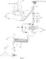
- FIG. 1 is a schematic diagram illustrating a hot briquetted iron (HBI) production apparatus according to one embodiment of the present invention
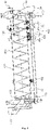
- FIG. 2 is a perspective view illustrating a cooler unit of the HBI production apparatus according to one embodiment of the present invention
- FIG. 3 is a front-side perspective view illustrating the cooler unit of the HBI production apparatus according to one embodiment of the present invention, the apparatus being viewed from a direction of an outlet
- FIG. 4 is a cross-sectional view taken along a line A-A' of FIG. 2
- FIG. 5 is a cross-sectional view taken along a line B-B' of FIG. 2 .
- the HBI production apparatus includes a feeder unit 100, a quantitative dispenser unit 200, a hot briquette forming unit 300, and a cooler unit 400.
- the feeder unit 100 cools and transports direct reduced iron (DRI) 1.
- the feeder unit 100 includes a cooler 110 and a conveyer 120. Iron oxides are reduced at a high temperature of 1000 °C to 1200 °C to become the DRI 1.
- the DRI 1 is then transported to the feeder unit 100. In such a high temperature range, the DRI particles may aggregate with each other so that it is difficult to transport or transform the DRI particles. Therefore, the DRI 1 that is discharged hot needs to be cooled by the cooler 110.
- the DRI 1 is cooled through indirect cooling in a nitrogen atmosphere environment.
- the cooler 110 is equipped with cooling water nozzles 112 on the outer surface thereof. When cooling water is supplied to the cooler 110 through a cooling water pipe, the cooling water is sprayed outward from the cooler 110.
- the feeder unit 100 may further include a cooling water cover that prevents the cooling water from escaping to other units or components.
- the cooler 110 performs indirect cooling on the DRI 1 and transports the DRI to the conveyer 120.
- the cooler 110 has a cylindrical main body which is connected to a motor 114. Thus, the main body of the cooler 110 is rotated by the motor 114.
- the cooler 110 is installed to be inclined toward the conveyer 120.
- the cooler 110 may further include a transport screw provided inside the main body. The transport screw rotates along with the main body of the cooler 110, thereby transporting the DRI 1.
- the DRI cooled by the cooler 110 is transported to the conveyer 120.
- the conveyer 120 is equipped with a bucket 122 for the transport of the DRI and a motor 124 for moving the conveyer 120.
- the conveyer 120 is a kind of chain conveyer.
- the bucket 122 is attached to a strand of chain that obliquely extends.
- the DRI is charged into the bucket 122 and then the bucket 122 moves down along the chain to the quantitative dispenser unit 200.
- the conveyer 120 may further include a guide member, a guide roller, a header chain roller, and a tail chain roller. While the DRI in the bucket 122 is being transported to the quantitative dispenser unit 200 by the conveyer 120, the DRI is further cooled down.
- the DRI transported to the quantitative dispenser unit 200 is pulverized in the quantitative dispenser unit 200, and a predetermined fixed amount of the DRI is fed into the hot briquette forming unit 300.
- the quantitative dispenser unit 200 includes: a pulverizer 210 that pulverizes the DRI into DRI particles with a predetermined size; a storage bin 220 that temporarily stores and discharges the DRI particles; and a diverter 240 that switches between moving paths of the DRI particles discharged from the storage bin 220.
- the pulverizer 210 pulverizes the DRI masses or lumps into DRI pellets or fines which are than charged into the storage bin 220 having a predetermined volume. Therefore, a fixed amount of DRI can be discharged from the quantitative dispenser unit 200.
- the pulverizer 210 is composed of a pair of rollers each of which is provided with grooves or saw-like impact bars.
- the rollers are combined with respective rotary shafts spaced a predetermined distance from each other.
- the pulverizer 210 includes a pair of rollers, rotary shafts combined with the respective rollers, two motors connected to the respective rotary shafts, and a pulverizer casing encasing the other components.
- the storage bin 220 is used to a buffering space that temporarily stores a fixed amount of DRI particles and discharges it.
- the DRI particles are transported to the next stage process by a feed leg 260.
- a shut-off valve 230 230 or a slide gate 250 may be provided between the storage bin 220 and the diverter 240 to control the discharge or the amount of discharge of the DRI particles.
- the shut-off valve 230 is used to prevent the discharge of the direct reduced iron when the HBI production apparatus is inspected, repaired, or experiences unexpected malfunctioning during the production process.
- the shut-off value 230 is composed of a valve body and a valve actuator.
- the slide gate 250 is a mechanical device that can control the discharge amount of the direct reduced iron.
- the amount of direct reduced iron in the force feeder 311 of the hot briquette forming unit 300 is detected and the degree of opening of the slide gate 250 is correspondingly controlled. In this manner, it is possible to adjust the amount of direct reduced iron that is input to the hot briquette forming unit (300).
- the slide gate 250 may be composed of a slide gate body, a gate, and a gate operating cylinder.
- the diverter 240 for switching the moving paths of the direct reduced iron discharged from the storage bin 220 is a device that can change the direction of movement of the direct reduced iron between two paths.
- HBI hot briquetted iron
- the diverter 240 guides the direct reduced iron to be transported toward the hot briquette forming unit 300.
- the diverter 240 guides the direct reduced iron to be transported toward a bypass line (not shown). That is, due to the presence of the diverter 240, it is possible to prepare for a situation in which the hot briquette forming unit 300 needs to be evacuated within a short time for some reasons, for example, in a case of an equipment failure or a certain emergency situation.
- the diverter 240 may be composed of a case, a damper, and a damper operating cylinder.
- the direct reduced iron transported to the quantitative dispenser unit 200 is pressed at a high temperature through the hot briquette forming unit 300, thereby being molded into hot briquetted iron 5.
- the hot briquette forming unit 300 may include a hot briquetting machine 310 and a separator 320.
- the hot briquetting machine 310 includes a pair of briquetting rollers 312 that directly press the direct reduced iron and a hydraulic device 314 that adjusts the pressing force of the briquetting rollers 312.
- the direct reduced iron supplied by the operation of the screw located inside the force feeder 311 is passed through a nip between the briquetting rollers 312 rotating in counter directions.
- the direct reduced iron particles are changed into hot iron briquettes.
- the briquetting rollers 312 may have a plurality of intaglio pockets, and the intaglio pockets may have a zigzag shape for higher molding efficiency.
- the HBI production apparatus may further include roller drive motors for rotating the briquetting rollers 312 and a reducer for adjusting the speed of rotation of the briquetting rollers 312, and a hydraulic cylinder and system 316 that adjusts the pressure of the hydraulic device.
- the hot briquetted iron (HBI) produced through hot pressing of the hot briquetting machine 310 has a continuous strip shape.
- the hot briquette forming unit 300 includes a separator 320.
- the separator 320 includes a guide frame, a rotor, a shaft, a casing, and a rotor drive motor.
- the briquettes discharged from the separator 320 are still hot (for example, a temperature of 550°C to 650°C. Therefore, it is difficult to carry and handle the briquettes.
- the cooler unit 400 includes a cylindrical body 410 and a transport screw 412 or blade and a cooling water spray nozzle 420 which are provided in the cylindrical body 410.
- the body has an inlet 430 on a first side thereof and an outlet 440 on a second side thereof, in which the first side and the second side are opposite to each other.
- the briquettes can be introduced into the body through the inlet 430 and can be discharged from the body through the outlet 440.
- cooling water is discharged from the body through the inlet 430.
- the cooler unit 400 may further include a device that rotates the body 410.
- the hot briquettes introduced into the body 410 through the inlet 430 are transported toward the outlet 440 by the transport screw 412 that rotates in conjunction with the body 410.
- the hot briquettes are cooled while being transported through the body 410, i.e., from the inlet to the outlet.
- the rotary blades of the transport screw 412 are arranged at intervals of 3 to 10 times the width or size of the hot iron briquettes, and the height of the rotary blades is 1 to 1.5 times the width or the size of the hot iron briquettes.
- the cooling water spray nozzle 420 is located in the vicinity of the outlet 440, and the cooling water moves to the cooling water spray nozzle 420 through the cooling water supply pipe 20. Since the cooler unit 400 is provided with the cooling water supply line 20 and the cooling water spray nozzle 420 located in the vicinity of the outlet 440, it is possible to directly spraying the cooling water onto the hot iron briquettes, thereby directly cooling the hot iron briquettes in the cylindrical body 410.
- the cooler unit 400 is obliquely installed such that the outlet 440 is positioned higher than the inlet 430.
- a blocking plate is provided inside the body 410 and is positioned close to the inlet 430. Therefore, it is possible to maintain a level of cooling water 22 in the body 410. That is, the cylindrical body is inclined such that the inlet 430 through which the hot iron briquettes are introduced into the body is relatively low and the outlet 440 through which the hot iron briquettes cooled by the cooling water are discharged from the body.
- cooling water 22 retained in the body and maintained at a predetermined water level primarily cools the hot iron briquettes introduced through the inlet 430, and cooling water sprayed from the cooling water spray nozzle 420 secondarily cools the hot iron briquettes that are primarily cooled by the retained cooling water and are then transported toward the outlet by the transport screw 412 or the blades.
- the hot iron briquettes are cooled in this manner by the cooler unit 400 and are then discharged from the cooler unit 400.
- the blocking plate 432 positioned close to the inlet 430 is fixedly welded to the body 410.
- the blocking plate 432 acts like a dam for retaining the cooling water 22, thereby securing a constant level of the cooling water 22 retained in the body 410.
- the cooling water 22 When the cooling water 22 is heated by heat-exchanging with the hot iron briquettes being present in the vicinity of the inlet 430, the water level rises and thus the heated cooling water overflows the blocking plate 432, thereby flowing out through the inlet 430. Since, cold cooling water is replenished, the temperature of the cooling water retained in the body is maintained below a predetermined temperature.
- the hot iron briquettes that are discharged hot i.e. temperature of 550°C to 650°C
- the hot iron briquettes are cooled through direct contact with the cooling water or the rotary cooler unit 400.
- the hot iron briquettes are finally cooled to a temperature of 80°C to 100°C so that they can be easily carried and handled. That is, since the HBI production apparatus according to an embodiment of the present invention is equipped with the cooler unit 400, it is possible to produce low-temperature iron briquettes from direct reduced iron that is discharged hot from a direct reduction furnace.
- the produced iron briquettes can be easily transported to a destination by using a general-purpose transport facility.
- the water level of the retention cooling water 22 is the same as the height of the blocking plate 432. For example, it may be 300 mm to 600 mm.
- the cooling water continuously supplied to the hot iron briquettes through the cooling water spray nozzle 420 overflows the blocking plate 432 and is thus discharged from the cooler unit 400 through the inlet 430.
- the cooling water that is discharged outside through the inlet is in a heated state.
- the heated cooling water flows into a cooling tower to be cooled again.
- This cooled cooling water is pumped by a cooling water circulation pump so as to be supplied again to the cooler unit 400 through the cooling water supply line 20 and the cooling water spray nozzle 420.
- the contact time during which the cooling water sprayed from the cooling water spray nozzle 420 is in contact with the hot iron briquettes is about 5 to 10 minutes.
- the time of contact between the retention cooling water and the hot iron briquettes is determined depending on the temperature of the retention cooling water 22 in the body of the cooler unit. For example, when the temperature of the retention cooling water 22 is higher than a proper temperature, that is, when excessively many hot iron briquettes are supplied to the cooler unit, the feed flow rate of the retention cooling water 22 so that the retention time of the cooling water in the body 410 is decreased. Thus, cooling effect can be enhanced.
- the feed flow rate of the retention cooling water 22 is reduced so that the retention time of the retention cooling water 22 in the body 410 is increased.
- the inclination angle of the body 410 of the cooler unit 400 is in a range of 2° to 15°.
- the inclination angle is determined depending on the diameter and length of the body 410. When the diameter of the body 410 of the cooler unit is relatively large and the length is relatively short, the inclination angle is increased.
- the cooling unit 400 includes a support 460 composed of a base frame 464, a support roller 462, and a guide roller 466.
- the support roller 462 provided between the base frame 464 and the body 410 supports the body 410 so that the rotational axis of the body does not shake during rotation of the body 410.
- the guide roller 466 prevents the linear movement of the body 410 in the backward-forward direction of the body 410. Therefore, although the body 410 of the cooler unit is inclined, the rotational motion of the body of the cooler unit can be stably performed due to the support 460.
- the cooler unit 400 further includes a rotating unit 470 for rotating the body 410, and the rotating unit 470 takes a gear type or chain type driving mechanism.
- the rotating unit 470 includes a motor 472 that provides driving force, a pinion gear 476 mounted on the motor 472, and a driving gear 474 mounted on the outer surface of the body 410 and configured to engage with the pinion gear 476.
- the cooler 400 may have a problem in that the internal temperature of the body 410 of the cooler unit 400 increases due to the vapor that occurs when the hot iron briquettes are cooled by the cooling water. In this case, it is difficult to cool the hot iron briquettes with the cooler unit 400. Therefore, the cooler unit 400 may further include a vapor discharge pump that pumps the vapor out of the body 410 of the cooler unit 400.
- the cooler unit 400 may further include a sieve member 450 for separating the cooling water 24 and the hot iron briquettes 5 in a discharge port of the outlet 440. Due to the presence of the sieve member 450, the cooling water 24 remaining on the iron briquettes can be removed. That is, the cooled iron briquettes 5 are strained and then transported to a transporting device 500 and then stored in a storage tank.
Landscapes
- Engineering & Computer Science (AREA)
- Chemical & Material Sciences (AREA)
- Manufacturing & Machinery (AREA)
- Organic Chemistry (AREA)
- Metallurgy (AREA)
- Materials Engineering (AREA)
- Geochemistry & Mineralogy (AREA)
- Geology (AREA)
- Life Sciences & Earth Sciences (AREA)
- General Life Sciences & Earth Sciences (AREA)
- Environmental & Geological Engineering (AREA)
- Mechanical Engineering (AREA)
- Manufacture Of Iron (AREA)
- Manufacture And Refinement Of Metals (AREA)
Claims (8)
- Vorrichtung zum Herstellen von heiß brikettiertem Eisen (HBI: Hot Briquetted Iron), wobei die Vorrichtung umfasst:eine Zuführeinheit (100), die eingerichtet ist, um direkt reduziertes Eisen, das als DRI (Direct Reduced Iron) (1) bezeichnet wird, zu kühlen und zu transportieren;eine quantitative Abgabeeinheit (200), die eingerichtet ist, um das DRI (1) zu pulverisieren und eine vorbestimmte feste Menge des pulverisierten DRI (1) auf einmal abzugeben;eine Heißbrikett-Bildungseinheit (300), die eingerichtet ist, um die feste Menge des DRI (1) heißzupressen, um Heißeisenbriketts zu bilden; undeine Kühlereinheit (400), die eingerichtet ist, um die Heißeisenbriketts zu kühlen,wobei die Kühlereinheit (400) umfasst: einen zylindrischen Körper (410) mit einem Einlass (430), der auf einer ersten Seite davon vorgesehen ist, und einem Auslass (440), der auf einer zweiten Seite davon vorgesehen ist, eine Kühlwasser-Sprühdüse (420), die im Inneren des zylindrischen Körpers (410) vorgesehen ist,und eine Transportschnecke (412) oder -schaufel, die eingerichtet ist, um die Heißeisenbriketts von dem Einlass (430) zu dem Auslass (440) zu transportieren, und in dem zylindrischen Körper (410) vorgesehen ist,wobei die Heißeisenbriketts in die Kühlereinheit (400) durch den Einlass (430) eingeführt und von der Kühlereinheit (400) durch den Auslass (440) abgegeben werden, wobei die Kühlereinheit (400) schräg installiert ist, so dass der Auslass (440) der Kühlereinheit (400) höher positioniert ist als der Einlass (430) undKühlwasser, das in dem Körper (410) der Kühlereinheit (400) enthalten ist, eingerichtet ist, um die Heißeisenbriketts zu kühlen, die durch den Einlass (430) eingeführt und durch den Einlass (430) nach außen abgegeben werden.
- Vorrichtung nach Anspruch 1, wobei Kühlwasser, das aus der Kühlwasser-Sprühdüse (420) der Kühlereinheit (400) gesprüht wird, eingerichtet ist, um die Heißeisenbriketts in zweiter Linie zu kühlen, die in erster Linie durch das enthaltene Kühlwasser gekühlt werden und dann durch die Transportschnecke (412) oder -schaufeln hin zu dem Auslass (440) transportiert werden.
- Vorrichtung nach Anspruch 1, wobei die Kühlereinheit (400) ferner ein Siebelement (450) umfasst, das an einer Abgabeöffnung des Auslasses (440) angeordnet ist, das eingerichtet ist, um die Heißeisenbriketts abzuseihen, so dass die Heißeisenbriketts ohne das Kühlwasser, das auf der Oberfläche der Briketts verbleibt, abgegeben werden.
- Vorrichtung nach Anspruch 1, wobei die Kühlereinheit (400) ferner eine Dreheinheit (470) umfasst, die eingerichtet ist, um den Körper (410) der Kühlereinheit (400) zu drehen.
- Vorrichtung nach Anspruch 1, wobei die Kühlereinheit (400) ferner eine Sperrplatte (432) umfasst, die im Inneren des Körpers (410) vorgesehen und nahe dem Einlass (430) positioniert ist, wodurch ein Kühlwasserspegel in dem Körper (410) aufrechterhalten wird.
- Vorrichtung nach Anspruch 1, wobei die Heißbrikett-Bildungseinheit (300) umfasst: eine Heißbrikettiermaschine (310), die Brikettierwalzen (312), die eingerichtet sind, um das DRI (1) bei einer hohen Temperatur zu pressen, um heiß brikettiertes Eisen zu bilden, und eine Hydraulikeinrichtung (314), die eingerichtet ist, um eine Presskraft der Brikettierwalzen (312) einzustellen, aufweist; und eine Trenneinrichtung (320), die eingerichtet ist, um das heiß brikettierte Eisen in die Heißeisenbriketts zu trennen.
- Vorrichtung nach Anspruch 1, wobei die quantitative Abgabeeinheit (200) umfasst: eine Pulverisiereinrichtung (210), die eingerichtet ist, um das DRI (1) in DRI-Partikel mit einer vorbestimmten Größe zu pulverisieren; einen Speicherbehälter (220), der eingerichtet ist, um die DRI-Partikel vorübergehend zu speichern und abzugeben; und eine Umlenkeinrichtung (240), die eingerichtet ist, um zwischen Bewegungswegen der DRI-Partikel, die von dem Speicherbehälter (220) abgegeben werden, umzuschalten.
- Vorrichtung nach Anspruch 1, wobei die Zuführeinheit (100) umfasst: einen Kühler (110), der eingerichtet ist, um das DRI (1) zu transportieren, während an dem DRI (1) ein indirektes Kühlen vorgenommen wird; und eine Fördereinrichtung (122), die mit einem Eimer versehen ist, der eingerichtet ist, um das gekühlte DRI (1), das darin gespeichert ist, zu transportieren.
Applications Claiming Priority (2)
| Application Number | Priority Date | Filing Date | Title |
|---|---|---|---|
| KR1020190051899A KR102077689B1 (ko) | 2019-05-03 | 2019-05-03 | 고온 브리켓 철의 제조장치 |
| PCT/KR2019/011238 WO2020226234A1 (ko) | 2019-05-03 | 2019-09-02 | 고온 브리켓 철의 제조장치 |
Publications (3)
| Publication Number | Publication Date |
|---|---|
| EP3760749A1 EP3760749A1 (de) | 2021-01-06 |
| EP3760749A4 EP3760749A4 (de) | 2021-09-01 |
| EP3760749B1 true EP3760749B1 (de) | 2022-12-07 |
Family
ID=69514175
Family Applications (1)
| Application Number | Title | Priority Date | Filing Date |
|---|---|---|---|
| EP19906597.0A Active EP3760749B1 (de) | 2019-05-03 | 2019-09-02 | Vorrichtung zur herstellung von eisenerzbriketts |
Country Status (6)
| Country | Link |
|---|---|
| US (1) | US20210238707A1 (de) |
| EP (1) | EP3760749B1 (de) |
| KR (1) | KR102077689B1 (de) |
| MX (1) | MX2020007488A (de) |
| RU (1) | RU2753212C1 (de) |
| WO (1) | WO2020226234A1 (de) |
Families Citing this family (4)
| Publication number | Priority date | Publication date | Assignee | Title |
|---|---|---|---|---|
| KR102390012B1 (ko) | 2020-06-09 | 2022-04-28 | 제일산기 주식회사 | 고온 브리켓 철의 냉각장치 |
| US12000011B2 (en) * | 2021-06-22 | 2024-06-04 | Midrex Technologies, Inc. | System and method for the production of hot briquetted iron (HBI) containing flux and/or carbonaceous material at a direct reduction plant |
| DE102022101419A1 (de) | 2022-01-21 | 2023-07-27 | Maschinenfabrik Köppern Gmbh & Co. Kg | Vorrichtung zum Zerteilen eines Brikettstrangs |
| KR102783842B1 (ko) | 2022-05-12 | 2025-03-21 | 제일산기 주식회사 | 가변 냉각방식이 적용된 고온 브리켓 철의 하이브리드 냉각장치 |
Family Cites Families (14)
| Publication number | Priority date | Publication date | Assignee | Title |
|---|---|---|---|---|
| US4093455A (en) * | 1975-06-05 | 1978-06-06 | Midrex Corporation | Compacted, passivated metallized iron product |
| JPS56150110A (en) * | 1980-04-24 | 1981-11-20 | Mitsubishi Heavy Ind Ltd | Forming equipment for hot briquet of reduced iron |
| DE19545985A1 (de) * | 1995-12-09 | 1997-06-12 | Metallgesellschaft Ag | Verfahren zum Heißbrikettieren von körnigem Eisenschwamm |
| JP4320917B2 (ja) * | 2000-05-22 | 2009-08-26 | 大同特殊鋼株式会社 | 還元ペレット連続冷却装置の使用方法 |
| JP3372934B2 (ja) * | 2000-06-02 | 2003-02-04 | 川崎重工業株式会社 | ステンレス鋼スラグの処理設備 |
| JP3616762B2 (ja) * | 2001-12-27 | 2005-02-02 | 株式会社御池鐵工所 | 廃棄物炭化炉 |
| US7938882B2 (en) * | 2007-04-02 | 2011-05-10 | Midrex Technologies, Inc. | Method and system for the supply of hot direct reduced iron for multiple uses |
| JP4317579B2 (ja) * | 2007-09-05 | 2009-08-19 | 新日本製鐵株式会社 | 還元鉄成形体の製造方法、及び銑鉄の製造方法 |
| JP5053011B2 (ja) * | 2007-09-19 | 2012-10-17 | 株式会社神戸製鋼所 | 熱間成形用還元鉄の温度制御方法 |
| JP5286880B2 (ja) * | 2008-03-28 | 2013-09-11 | 新日鐵住金株式会社 | スラグの冷却方法 |
| JP2011214122A (ja) * | 2010-04-02 | 2011-10-27 | Nippon Steel Engineering Co Ltd | ホットブリケットの製造方法および製造設備 |
| JP2012144788A (ja) | 2011-01-13 | 2012-08-02 | Kobe Steel Ltd | ホットブリケットアイアンの製造方法、およびその製造装置 |
| KR101244820B1 (ko) | 2011-04-05 | 2013-04-01 | 제일산기 주식회사 | 브리켓팅 장치 |
| KR20130110591A (ko) * | 2012-03-29 | 2013-10-10 | 현대제철 주식회사 | 브리켓 제조 장치 및 이를 이용한 브리켓 제조 방법 |
-
2019
- 2019-05-03 KR KR1020190051899A patent/KR102077689B1/ko active Active
- 2019-09-02 EP EP19906597.0A patent/EP3760749B1/de active Active
- 2019-09-02 RU RU2020122093A patent/RU2753212C1/ru active
- 2019-09-02 US US16/962,091 patent/US20210238707A1/en not_active Abandoned
- 2019-09-02 MX MX2020007488A patent/MX2020007488A/es unknown
- 2019-09-02 WO PCT/KR2019/011238 patent/WO2020226234A1/ko not_active Ceased
Also Published As
| Publication number | Publication date |
|---|---|
| US20210238707A1 (en) | 2021-08-05 |
| RU2753212C1 (ru) | 2021-08-12 |
| KR102077689B1 (ko) | 2020-02-14 |
| WO2020226234A1 (ko) | 2020-11-12 |
| EP3760749A1 (de) | 2021-01-06 |
| MX2020007488A (es) | 2021-02-09 |
| EP3760749A4 (de) | 2021-09-01 |
Similar Documents
| Publication | Publication Date | Title |
|---|---|---|
| EP3760749B1 (de) | Vorrichtung zur herstellung von eisenerzbriketts | |
| KR102389265B1 (ko) | 벌크 재료의 냉각 | |
| US9200346B2 (en) | Dry granulation of metallurgical slag | |
| RU2434948C2 (ru) | Способ и система подачи горячего железа прямого восстановления для многочисленных потребителей | |
| US9115413B2 (en) | Apparatus and methods for producing direct reduced iron | |
| CN107250078B (zh) | 一种回收钢铁生产步骤中产生的白渣的装置 | |
| US6214086B1 (en) | Direct reduced iron discharge system and method | |
| US4076520A (en) | Method for continuous passivation of sponge iron material | |
| KR100673785B1 (ko) | 산화 금속 환원용 설비와 그 조작 방법 및 환원로용 원재료의 성형물 | |
| CN113774202A (zh) | 热压铁块的冷却装置 | |
| WO2009016443A1 (fr) | Procédé de traitement de scorie sortant d'une cuve métallurgique et dispositif de mise en oeuvre de ce procédé | |
| EP3023480B1 (de) | Vorrichtung zur herstellung von kohlebriketts | |
| KR20080082649A (ko) | 컨베이어 시스템, 복합 시스템 및 금속 야금학적 방법의결합 방법 | |
| CN102388153B (zh) | 高密度还原铁的制造方法以及高密度还原铁的制造装置 | |
| US7687018B2 (en) | Means for conveying material | |
| JP3583067B2 (ja) | 移動炉床式熱処理炉の排出装置およびその操業方法 | |
| JP2002105518A (ja) | 回転炉床式の金属還元炉及び酸化金属の還元方法 | |
| JP2001234256A (ja) | 回転炉床式還元炉の操業方法、および、還元炉原料の成形体 | |
| KR20190084604A (ko) | 스크류형의 직접환원철법 냉각장치 | |
| CN222048594U (zh) | 一种用于烧结环冷机卸料的运转小车 | |
| CN118910344B (zh) | 一种用于钒钛矿冶炼的高炉喷吹煤粉预热装置 | |
| CN113834342B (zh) | 一种鼓风式烧结余热回收造块装置及方法 | |
| JP2013029251A (ja) | 輻射式冷却装置及び還元鉄製造方法 | |
| CN205188382U (zh) | 一种采用链斗式提升卸料机的环式培烧机 | |
| CN118910355A (zh) | 一种金属化球团连续热装热送熔分冶炼的系统及方法 |
Legal Events
| Date | Code | Title | Description |
|---|---|---|---|
| STAA | Information on the status of an ep patent application or granted ep patent |
Free format text: STATUS: UNKNOWN |
|
| STAA | Information on the status of an ep patent application or granted ep patent |
Free format text: STATUS: THE INTERNATIONAL PUBLICATION HAS BEEN MADE |
|
| PUAI | Public reference made under article 153(3) epc to a published international application that has entered the european phase |
Free format text: ORIGINAL CODE: 0009012 |
|
| STAA | Information on the status of an ep patent application or granted ep patent |
Free format text: STATUS: REQUEST FOR EXAMINATION WAS MADE |
|
| 17P | Request for examination filed |
Effective date: 20200709 |
|
| AK | Designated contracting states |
Kind code of ref document: A1 Designated state(s): AL AT BE BG CH CY CZ DE DK EE ES FI FR GB GR HR HU IE IS IT LI LT LU LV MC MK MT NL NO PL PT RO RS SE SI SK SM TR |
|
| AX | Request for extension of the european patent |
Extension state: BA ME |
|
| RIN1 | Information on inventor provided before grant (corrected) |
Inventor name: PARK, SANG KUI |
|
| A4 | Supplementary search report drawn up and despatched |
Effective date: 20210730 |
|
| RIC1 | Information provided on ipc code assigned before grant |
Ipc: C22B 1/24 20060101AFI20210726BHEP Ipc: C22B 1/248 20060101ALI20210726BHEP Ipc: C21B 13/00 20060101ALI20210726BHEP Ipc: C21B 13/10 20060101ALI20210726BHEP Ipc: B30B 11/16 20060101ALI20210726BHEP Ipc: C22B 1/26 20060101ALI20210726BHEP |
|
| STAA | Information on the status of an ep patent application or granted ep patent |
Free format text: STATUS: EXAMINATION IS IN PROGRESS |
|
| 17Q | First examination report despatched |
Effective date: 20211221 |
|
| REG | Reference to a national code |
Ref country code: DE Ref legal event code: R079 Ref document number: 602019023020 Country of ref document: DE Free format text: PREVIOUS MAIN CLASS: C22B0001240000 Ipc: C21B0013000000 |
|
| GRAP | Despatch of communication of intention to grant a patent |
Free format text: ORIGINAL CODE: EPIDOSNIGR1 |
|
| STAA | Information on the status of an ep patent application or granted ep patent |
Free format text: STATUS: GRANT OF PATENT IS INTENDED |
|
| DAV | Request for validation of the european patent (deleted) | ||
| DAX | Request for extension of the european patent (deleted) | ||
| RIC1 | Information provided on ipc code assigned before grant |
Ipc: B30B 15/32 20060101ALN20220707BHEP Ipc: C22B 1/26 20060101ALI20220707BHEP Ipc: C22B 1/24 20060101ALI20220707BHEP Ipc: B30B 11/16 20060101ALI20220707BHEP Ipc: C21B 13/00 20060101AFI20220707BHEP |
|
| INTG | Intention to grant announced |
Effective date: 20220726 |
|
| GRAS | Grant fee paid |
Free format text: ORIGINAL CODE: EPIDOSNIGR3 |
|
| GRAA | (expected) grant |
Free format text: ORIGINAL CODE: 0009210 |
|
| STAA | Information on the status of an ep patent application or granted ep patent |
Free format text: STATUS: THE PATENT HAS BEEN GRANTED |
|
| AK | Designated contracting states |
Kind code of ref document: B1 Designated state(s): AL AT BE BG CH CY CZ DE DK EE ES FI FR GB GR HR HU IE IS IT LI LT LU LV MC MK MT NL NO PL PT RO RS SE SI SK SM TR |
|
| REG | Reference to a national code |
Ref country code: GB Ref legal event code: FG4D |
|
| REG | Reference to a national code |
Ref country code: CH Ref legal event code: EP Ref country code: AT Ref legal event code: REF Ref document number: 1536333 Country of ref document: AT Kind code of ref document: T Effective date: 20221215 |
|
| REG | Reference to a national code |
Ref country code: DE Ref legal event code: R096 Ref document number: 602019023020 Country of ref document: DE |
|
| REG | Reference to a national code |
Ref country code: IE Ref legal event code: FG4D |
|
| REG | Reference to a national code |
Ref country code: LT Ref legal event code: MG9D |
|
| REG | Reference to a national code |
Ref country code: NL Ref legal event code: MP Effective date: 20221207 |
|
| PG25 | Lapsed in a contracting state [announced via postgrant information from national office to epo] |
Ref country code: SE Free format text: LAPSE BECAUSE OF FAILURE TO SUBMIT A TRANSLATION OF THE DESCRIPTION OR TO PAY THE FEE WITHIN THE PRESCRIBED TIME-LIMIT Effective date: 20221207 Ref country code: NO Free format text: LAPSE BECAUSE OF FAILURE TO SUBMIT A TRANSLATION OF THE DESCRIPTION OR TO PAY THE FEE WITHIN THE PRESCRIBED TIME-LIMIT Effective date: 20230307 Ref country code: LT Free format text: LAPSE BECAUSE OF FAILURE TO SUBMIT A TRANSLATION OF THE DESCRIPTION OR TO PAY THE FEE WITHIN THE PRESCRIBED TIME-LIMIT Effective date: 20221207 Ref country code: FI Free format text: LAPSE BECAUSE OF FAILURE TO SUBMIT A TRANSLATION OF THE DESCRIPTION OR TO PAY THE FEE WITHIN THE PRESCRIBED TIME-LIMIT Effective date: 20221207 Ref country code: ES Free format text: LAPSE BECAUSE OF FAILURE TO SUBMIT A TRANSLATION OF THE DESCRIPTION OR TO PAY THE FEE WITHIN THE PRESCRIBED TIME-LIMIT Effective date: 20221207 |
|
| REG | Reference to a national code |
Ref country code: AT Ref legal event code: MK05 Ref document number: 1536333 Country of ref document: AT Kind code of ref document: T Effective date: 20221207 |
|
| PG25 | Lapsed in a contracting state [announced via postgrant information from national office to epo] |
Ref country code: RS Free format text: LAPSE BECAUSE OF FAILURE TO SUBMIT A TRANSLATION OF THE DESCRIPTION OR TO PAY THE FEE WITHIN THE PRESCRIBED TIME-LIMIT Effective date: 20221207 Ref country code: PL Free format text: LAPSE BECAUSE OF FAILURE TO SUBMIT A TRANSLATION OF THE DESCRIPTION OR TO PAY THE FEE WITHIN THE PRESCRIBED TIME-LIMIT Effective date: 20221207 Ref country code: LV Free format text: LAPSE BECAUSE OF FAILURE TO SUBMIT A TRANSLATION OF THE DESCRIPTION OR TO PAY THE FEE WITHIN THE PRESCRIBED TIME-LIMIT Effective date: 20221207 Ref country code: HR Free format text: LAPSE BECAUSE OF FAILURE TO SUBMIT A TRANSLATION OF THE DESCRIPTION OR TO PAY THE FEE WITHIN THE PRESCRIBED TIME-LIMIT Effective date: 20221207 Ref country code: GR Free format text: LAPSE BECAUSE OF FAILURE TO SUBMIT A TRANSLATION OF THE DESCRIPTION OR TO PAY THE FEE WITHIN THE PRESCRIBED TIME-LIMIT Effective date: 20230308 |
|
| PG25 | Lapsed in a contracting state [announced via postgrant information from national office to epo] |
Ref country code: NL Free format text: LAPSE BECAUSE OF FAILURE TO SUBMIT A TRANSLATION OF THE DESCRIPTION OR TO PAY THE FEE WITHIN THE PRESCRIBED TIME-LIMIT Effective date: 20221207 |
|
| PG25 | Lapsed in a contracting state [announced via postgrant information from national office to epo] |
Ref country code: SM Free format text: LAPSE BECAUSE OF FAILURE TO SUBMIT A TRANSLATION OF THE DESCRIPTION OR TO PAY THE FEE WITHIN THE PRESCRIBED TIME-LIMIT Effective date: 20221207 Ref country code: RO Free format text: LAPSE BECAUSE OF FAILURE TO SUBMIT A TRANSLATION OF THE DESCRIPTION OR TO PAY THE FEE WITHIN THE PRESCRIBED TIME-LIMIT Effective date: 20221207 Ref country code: PT Free format text: LAPSE BECAUSE OF FAILURE TO SUBMIT A TRANSLATION OF THE DESCRIPTION OR TO PAY THE FEE WITHIN THE PRESCRIBED TIME-LIMIT Effective date: 20230410 Ref country code: EE Free format text: LAPSE BECAUSE OF FAILURE TO SUBMIT A TRANSLATION OF THE DESCRIPTION OR TO PAY THE FEE WITHIN THE PRESCRIBED TIME-LIMIT Effective date: 20221207 Ref country code: CZ Free format text: LAPSE BECAUSE OF FAILURE TO SUBMIT A TRANSLATION OF THE DESCRIPTION OR TO PAY THE FEE WITHIN THE PRESCRIBED TIME-LIMIT Effective date: 20221207 Ref country code: AT Free format text: LAPSE BECAUSE OF FAILURE TO SUBMIT A TRANSLATION OF THE DESCRIPTION OR TO PAY THE FEE WITHIN THE PRESCRIBED TIME-LIMIT Effective date: 20221207 |
|
| PG25 | Lapsed in a contracting state [announced via postgrant information from national office to epo] |
Ref country code: SK Free format text: LAPSE BECAUSE OF FAILURE TO SUBMIT A TRANSLATION OF THE DESCRIPTION OR TO PAY THE FEE WITHIN THE PRESCRIBED TIME-LIMIT Effective date: 20221207 Ref country code: IS Free format text: LAPSE BECAUSE OF FAILURE TO SUBMIT A TRANSLATION OF THE DESCRIPTION OR TO PAY THE FEE WITHIN THE PRESCRIBED TIME-LIMIT Effective date: 20230407 Ref country code: AL Free format text: LAPSE BECAUSE OF FAILURE TO SUBMIT A TRANSLATION OF THE DESCRIPTION OR TO PAY THE FEE WITHIN THE PRESCRIBED TIME-LIMIT Effective date: 20221207 |
|
| REG | Reference to a national code |
Ref country code: DE Ref legal event code: R097 Ref document number: 602019023020 Country of ref document: DE |
|
| PLBE | No opposition filed within time limit |
Free format text: ORIGINAL CODE: 0009261 |
|
| STAA | Information on the status of an ep patent application or granted ep patent |
Free format text: STATUS: NO OPPOSITION FILED WITHIN TIME LIMIT |
|
| PG25 | Lapsed in a contracting state [announced via postgrant information from national office to epo] |
Ref country code: DK Free format text: LAPSE BECAUSE OF FAILURE TO SUBMIT A TRANSLATION OF THE DESCRIPTION OR TO PAY THE FEE WITHIN THE PRESCRIBED TIME-LIMIT Effective date: 20221207 |
|
| 26N | No opposition filed |
Effective date: 20230908 |
|
| PG25 | Lapsed in a contracting state [announced via postgrant information from national office to epo] |
Ref country code: SI Free format text: LAPSE BECAUSE OF FAILURE TO SUBMIT A TRANSLATION OF THE DESCRIPTION OR TO PAY THE FEE WITHIN THE PRESCRIBED TIME-LIMIT Effective date: 20221207 |
|
| P01 | Opt-out of the competence of the unified patent court (upc) registered |
Effective date: 20231116 |
|
| REG | Reference to a national code |
Ref country code: CH Ref legal event code: PL |
|
| PG25 | Lapsed in a contracting state [announced via postgrant information from national office to epo] |
Ref country code: LU Free format text: LAPSE BECAUSE OF NON-PAYMENT OF DUE FEES Effective date: 20230902 |
|
| REG | Reference to a national code |
Ref country code: BE Ref legal event code: MM Effective date: 20230930 |
|
| GBPC | Gb: european patent ceased through non-payment of renewal fee |
Effective date: 20230902 |
|
| PG25 | Lapsed in a contracting state [announced via postgrant information from national office to epo] |
Ref country code: LU Free format text: LAPSE BECAUSE OF NON-PAYMENT OF DUE FEES Effective date: 20230902 Ref country code: IT Free format text: LAPSE BECAUSE OF FAILURE TO SUBMIT A TRANSLATION OF THE DESCRIPTION OR TO PAY THE FEE WITHIN THE PRESCRIBED TIME-LIMIT Effective date: 20221207 Ref country code: MC Free format text: LAPSE BECAUSE OF FAILURE TO SUBMIT A TRANSLATION OF THE DESCRIPTION OR TO PAY THE FEE WITHIN THE PRESCRIBED TIME-LIMIT Effective date: 20221207 |
|
| REG | Reference to a national code |
Ref country code: IE Ref legal event code: MM4A |
|
| PG25 | Lapsed in a contracting state [announced via postgrant information from national office to epo] |
Ref country code: IE Free format text: LAPSE BECAUSE OF NON-PAYMENT OF DUE FEES Effective date: 20230902 |
|
| PG25 | Lapsed in a contracting state [announced via postgrant information from national office to epo] |
Ref country code: GB Free format text: LAPSE BECAUSE OF NON-PAYMENT OF DUE FEES Effective date: 20230902 |
|
| PG25 | Lapsed in a contracting state [announced via postgrant information from national office to epo] |
Ref country code: CH Free format text: LAPSE BECAUSE OF NON-PAYMENT OF DUE FEES Effective date: 20230930 |
|
| PG25 | Lapsed in a contracting state [announced via postgrant information from national office to epo] |
Ref country code: IE Free format text: LAPSE BECAUSE OF NON-PAYMENT OF DUE FEES Effective date: 20230902 Ref country code: GB Free format text: LAPSE BECAUSE OF NON-PAYMENT OF DUE FEES Effective date: 20230902 Ref country code: CH Free format text: LAPSE BECAUSE OF NON-PAYMENT OF DUE FEES Effective date: 20230930 |
|
| PG25 | Lapsed in a contracting state [announced via postgrant information from national office to epo] |
Ref country code: BE Free format text: LAPSE BECAUSE OF NON-PAYMENT OF DUE FEES Effective date: 20230930 |
|
| PG25 | Lapsed in a contracting state [announced via postgrant information from national office to epo] |
Ref country code: BG Free format text: LAPSE BECAUSE OF FAILURE TO SUBMIT A TRANSLATION OF THE DESCRIPTION OR TO PAY THE FEE WITHIN THE PRESCRIBED TIME-LIMIT Effective date: 20221207 |
|
| PG25 | Lapsed in a contracting state [announced via postgrant information from national office to epo] |
Ref country code: BG Free format text: LAPSE BECAUSE OF FAILURE TO SUBMIT A TRANSLATION OF THE DESCRIPTION OR TO PAY THE FEE WITHIN THE PRESCRIBED TIME-LIMIT Effective date: 20221207 |
|
| PG25 | Lapsed in a contracting state [announced via postgrant information from national office to epo] |
Ref country code: CY Free format text: LAPSE BECAUSE OF FAILURE TO SUBMIT A TRANSLATION OF THE DESCRIPTION OR TO PAY THE FEE WITHIN THE PRESCRIBED TIME-LIMIT; INVALID AB INITIO Effective date: 20190902 |
|
| PG25 | Lapsed in a contracting state [announced via postgrant information from national office to epo] |
Ref country code: HU Free format text: LAPSE BECAUSE OF FAILURE TO SUBMIT A TRANSLATION OF THE DESCRIPTION OR TO PAY THE FEE WITHIN THE PRESCRIBED TIME-LIMIT; INVALID AB INITIO Effective date: 20190902 |
|
| PGFP | Annual fee paid to national office [announced via postgrant information from national office to epo] |
Ref country code: FR Payment date: 20250922 Year of fee payment: 7 |
|
| PG25 | Lapsed in a contracting state [announced via postgrant information from national office to epo] |
Ref country code: TR Free format text: LAPSE BECAUSE OF FAILURE TO SUBMIT A TRANSLATION OF THE DESCRIPTION OR TO PAY THE FEE WITHIN THE PRESCRIBED TIME-LIMIT Effective date: 20221207 |
|
| PGFP | Annual fee paid to national office [announced via postgrant information from national office to epo] |
Ref country code: DE Payment date: 20250930 Year of fee payment: 7 |