EP3023480B1 - Vorrichtung zur herstellung von kohlebriketts - Google Patents
Vorrichtung zur herstellung von kohlebriketts Download PDFInfo
- Publication number
- EP3023480B1 EP3023480B1 EP14826739.6A EP14826739A EP3023480B1 EP 3023480 B1 EP3023480 B1 EP 3023480B1 EP 14826739 A EP14826739 A EP 14826739A EP 3023480 B1 EP3023480 B1 EP 3023480B1
- Authority
- EP
- European Patent Office
- Prior art keywords
- rotation
- crushing plates
- rotors
- crushing
- mixture
- Prior art date
- Legal status (The legal status is an assumption and is not a legal conclusion. Google has not performed a legal analysis and makes no representation as to the accuracy of the status listed.)
- Not-in-force
Links
Images


Classifications
-
- C—CHEMISTRY; METALLURGY
- C10—PETROLEUM, GAS OR COKE INDUSTRIES; TECHNICAL GASES CONTAINING CARBON MONOXIDE; FUELS; LUBRICANTS; PEAT
- C10L—FUELS NOT OTHERWISE PROVIDED FOR; NATURAL GAS; SYNTHETIC NATURAL GAS OBTAINED BY PROCESSES NOT COVERED BY SUBCLASSES C10G OR C10K; LIQUIFIED PETROLEUM GAS; USE OF ADDITIVES TO FUELS OR FIRES; FIRE-LIGHTERS
- C10L5/00—Solid fuels
- C10L5/02—Solid fuels such as briquettes consisting mainly of carbonaceous materials of mineral or non-mineral origin
- C10L5/06—Methods of shaping, e.g. pelletizing or briquetting
- C10L5/10—Methods of shaping, e.g. pelletizing or briquetting with the aid of binders, e.g. pretreated binders
-
- C—CHEMISTRY; METALLURGY
- C10—PETROLEUM, GAS OR COKE INDUSTRIES; TECHNICAL GASES CONTAINING CARBON MONOXIDE; FUELS; LUBRICANTS; PEAT
- C10L—FUELS NOT OTHERWISE PROVIDED FOR; NATURAL GAS; SYNTHETIC NATURAL GAS OBTAINED BY PROCESSES NOT COVERED BY SUBCLASSES C10G OR C10K; LIQUIFIED PETROLEUM GAS; USE OF ADDITIVES TO FUELS OR FIRES; FIRE-LIGHTERS
- C10L5/00—Solid fuels
- C10L5/02—Solid fuels such as briquettes consisting mainly of carbonaceous materials of mineral or non-mineral origin
- C10L5/34—Other details of the shaped fuels, e.g. briquettes
- C10L5/36—Shape
- C10L5/361—Briquettes
Definitions
- the present invention relates to a coal briquette manufacturing apparatus. More particularly, the present invention relates to a coal briquette manufacturing apparatus that can minimize attachment of coal when lump coal is crushed.
- a reducing furnace reducing iron ores and a melter-gasifier melting reduced iron ores are used.
- coal briquettes are charged into the melter-gasifier.
- reduced irons are melted in the melter-gasifier, transformed to molten iron and slag, and then discharged outside.
- the coal briquettes charged into the melter-gasifier form a coal-packed bed.
- oxygen is injected through a tuyere installed in the melter-gasifier, the coal-packed bed is burned to generate combustion gas.
- the combustion gas is transformed into reduction gas at a high temperature while increasing a temperature through the coal-packed bed.
- the high-temperature reduction gas is discharged outside the melter-gasifier to be supplied to the reducing furnace as the reducing gas.
- Reaction efficiency and heat-transfer efficiency may be increased by ensuring permeability and flow so that gas and liquid smoothly pass through the melter-gastifier.
- the coal briquettes are manufactured in the shape of predetermined-sized briquettes by mixing coal containing a sufficient amount of moisture and molasses and then compression-molding the mixture in the molding device.
- the molding device is formed of two compression molding rolls provided in a lower portion thereof and a gravity feeder provided in an upper portion thereof to feed coal to the molding rolls. Further, the gravity feeder is provided with a chopper to crush lump coal among coals fed into the gravity feeder. When the lump coal is provided directly into the gravity feeder, the lump coal is grown to a ball having a large diameter, thereby causing deterioration of quality of coal briquettes.
- the chopper has a structure in which a rotation shaft where a plurality of crushing plates are installed rotates to crush lumped coals.
- the present invention has been made in an effort to provide a coal briquette manufacturing apparatus that can clearly crush lumped coals.
- the present invention provides a coal briquette manufacturing apparatus that can minimize occurrence of attachment of coals when crushing coals.
- a coal briquette manufacturing apparatus includes a mixer forming a mixture of powdered coal and a binder, a gravity feeder connected to a lower end of the mixer and feeding the mixture, a molding device connected to a lower end of the gravity feeder and molding the mixture fed from the gravity feeder, and a crusher provided between the mixer and an upper end of the gravity feeder and crushing the mixture to be flown into the gravity feeder, is characterised in that the crusher may include rotation rotors rotatably provided in a housing and having crushing plates disposed at a distance from each other along the shaft direction, a driver rotating the rotation rotors, and a scraper member provided in the housing and disposed in front surfaces of the crushing plates to scrape mixtures attached to the crushing plates.
- the rotation rotors may include at least two rotation rotors and arranged in parallel with each other in the housing, and crushing plates provided in each of neighboring rotation rotors may be alternately arranged
- the scraper member may include an upper end portion extended toward the crushing plates and having a groove through which the crushing plate passes formed at location corresponding to each crushing plate of the rotation rotor and a lower end portion connected to a lower end of the upper end portion and extended downward while passing through the crushing plates of the rotation rotor to guide a mixture.
- the scraper member formed with a structure in which the upper end portion located in the crushing plate may be inclined with respect to a rotation direction of the rotation rotor.
- the two neighboring rotation rotors may have different rotation directions.
- the two neighboring rotation rotors may have different rotation speed.
- the coal briquette manufacturing apparatus may further include a reduction gear provided between the two neighboring rotation rotors and differentiating relative rotation speed of the two rotation rotors.
- Crushing plates provided in one rotation rotor among the two neighboring rotation rotors may be formed in the shape of a round plate, and crushing plates of the other rotation rotor may have a structure in which a plurality of wings extended in a radial direction are arranged while respectively having an angle along a circumference direction.
- attachment of coals in a coal crushing process can be prevented, and lumps of coal can be surely crushed such that quality of coal briquette can be improved.
- coal attachment can be minimized, the process can be continued, thereby improving productivity.
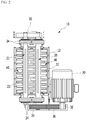
- FIG. 1 schematically illustrates a coal briquette manufacturing apparatus according to an exemplary embodiment of the present invention.
- a coal briquette manufacturing apparatus 100 of FIG. 1 is an example of the present invention, and the present invention is not limited thereto. Thus, a structure of the coal briquette manufacturing apparatus 100 can be variously modified.
- the coal briquette manufacturing apparatus 100 includes a mixer 110 mixing powdered coal and a binder, a molding device 120 manufacturing briquettes by compression-molding the mixture of the coal and the binder, and a gravity feeder 130 feeding the mixture to the molding device 120.
- the coal briquette manufacturing apparatus 100 may further include other constituent elements, for example, at least one of kneaders 140 connected to a rear end of the mixer 110 and kneading the mixture and a transfer screw 150 that transfers a mixture discharged from the kneader 140.
- the transfer screw 150 that transfers the mixture discharged from the mixture 110 is provided in an upper end of the gravity feeder 130, and a crusher 10 that crushes a lump of coal included in the mixture fed to the gravity feeder 130 is provided between the transfer screw 150 and an upper end of the gravity feeder 130.
- the crusher 10 crushes a lump of coal of which the size of greater than or equal to a predetermine size.
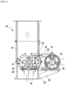
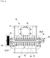
- FIG. 2 to FIG. 4 exemplarily illustrate a structure of the crusher 10 according to the present exemplary embodiment.
- the crusher 10 includes rotation rotors 20 and 21 rotatably provided in a housing 12 and where crushing plates 22 and 23 are provided with a gap therebetween along a shaft direction, a driver that drives the rotation rotors 20 ad 21, and a scraper member 40 provided in the housing 12 and disposed in the front surfaces of crushing plates 22 and 23 so as to scrape the mixture attached to the crushing plates 22 and 23.
- the mixture attached to the crushing plates 22 and 23 of the rotation rotors 20 and 21 is continuously removed by the scraper member 40 and thus the crushing plates 22 and 23 can be maintained in a clean state, and accordingly, crushing of lumps of coal can be continuously performed without stopping the operation.
- the mixture implies viscid coal mixed with a binder.
- the housing 12 forms an outer shape of the crusher 10, and an opening and closing door 14 is provided in the side surface of the crusher 10 to check the inside thereof.
- the housing 12 is formed in the shape of a quadrangular container into which the mixture moves, and an upper end and a lower end of the housing 12 are respectively connected to an outlet of the transfer screw 150 and an upper end inlet of the gravity feeder 130.
- the rotation rotors 20 and 21 are rotatable provided in a horizontal direction in the housing 12.
- a plurality of crushing plates 22 and 23 are respectively provided at a distance from each other along the shaft direction.
- the shafts of the rotation rotors 20 and 21 are rotatably supported by bearing blocks 24 provided in the housing 12.
- the driver may include a driving motor 30, a driving wheel 32 provided in the driving shaft, a driven wheel 34 provided in the shaft of the rotation rotor 20, and a belt 36 connected to the driving wheel 32 and the driven wheel 34.
- the driving motor 30 operates, power is transferred to the rotation rotor 20 through the driving wheel 32, the belt 36, and the driven wheel 34 such that the rotation rotor 20 rotates.
- two rotation rotors 20 and 21 are provided and disposed in parallel with each other in the housing 12.
- the crushing plates 22 and 23 provided in the respective rotation rotors 20 and 21 are alternately arranged between the neighboring rotation rotors 20 and 21.
- the alternate arrangement implies that crushing plates 22 and 23 provided in rotation rotors 20 and 21 overlap crushing plates 22 and 23 of other rotation rotors 20 and 21 that neighbor between the crushing plates 22 and 23 such that the crushing plates 22 and 23 are alternately arranged.
- the crushing plates 22 and 23 may have a thickness that is smaller than a gap between crushing plates 22 and 23 and other crushing plates 22 and 23 that are engaged with each other such that the crushing plates 22 and 23 can respectively rotate between the respectively engaged crushing plates 22 and 23.
- crushing plates 22 and 23 provided in each rotation rotor 20 and 21 scrape mixtures attached to neighboring crushing plates 22 and 23 while passing therebetween such that the mixtures can be prevented from being attached to the crushing plates 22 and 23.
- One rotation rotor 20 among the two rotation rotors 20 and 21 is connected with the driver.
- the other rotation rotor 21 receives power from the rotation rotor 20 and rotates. Accordingly, the crushing plates 22 and 23 provided in the rotation rotors 20 and 21 rotate and thus lumped coals included in the mixture are crushed.
- the scraping member 40 separates the viscid mixture attached to the front surfaces of the crushing plates 22 and 23 by scraping the same, and this will be described in detail later.
- the two rotation rotors 20 and 21 have different rotation directions. That is, as shown in FIG. 3 , the respective rotation rotors disposed in the left and right sides of the drawing respectively rotate in the clockwise direction and the counterclockwise direction.
- the mixture charged into the housing 12 are passed through between the rotation rotors 20 and 21 by the two rotating rotation rotors 20 and 21 and then moved downward. In such a process, the lumped coals included in the mixture are crushed by the crushing plates 22 and 23 rotating in the two rotation rotors 20 and 21.
- every neighboring two rotation rotors 20 and 21 have different rotation speed.
- a reduction gear 50 is provided between the two rotation rotors 20 and 21, and differentiates relative rotation speed of the two rotation rotors 20 and 21 while providing power between the two rotation rotors 20 and 21.
- a relative rotation speed difference between the two rotation rotors 20 and 21 is variously changed, and not limited to a specific value.
- the reduction gear 50 may be formed of, for example, gear groups respectively provided in the two rotation rotors 20 and 21 and each having a different number of teeth.
- the rotation rotor 20 connected to the driver rotates
- the other rotation rotor 21 connected to the reduction gear 50 rotates.
- the rotation rotor 20 connected to the driving motor and the rotation rotor 21 connected through the reduction gear 50 have different rotation speed. Accordingly, the two rotation rotors 20 and 21 respectively rotate with different speed.
- the respective crushing plates 22 and 23 provided in the two rotation rotors 20 and 21 may be formed in shapes that are different from each other.
- the crushing plate 23 provided in one rotation rotor 21 is formed in the shape of a round plate
- the crushing plate 22 provided in the other rotation rotor 20 is formed with a structure in which a plurality of wings 25 extended in a radial direction are arranged while each having an angle along a circumference direction.
- the wings 25 of each crushing plate 22 may be formed in the same location along the shaft direction of the rotation rotor, or may be formed respectively in different locations.
- the viscid mixture attached to the crushing plates 22 and 23 are scrapped by the scraper member attached to the front side of the crushing plates 22 and 23 and thus completely separated from the crushing plates 22 and 23.
- the scraper member 40 is extended along the shaft direction of the rotation rotors 20 and 21 in the housing 12 and thus lateral front ends thereof are fixed to the housing 12.
- Two scraper members 40 are provided corresponding to the crushing plates 22 and 23 provided in the respective rotation rotors 20 and 21.
- Each scraper member 40 includes an upper end portion 41 extended toward the crushing plates 22 and 23 and where grooves 42 through which the crushing plates 22 and 23 pass are formed at corresponding locations of the crushing plates 22 and 23 of the rotation rotors 20 and 21 to scrap coal attached to the crushing plates 22 and 23 and a lower end portion 44 connected to a lower end of the upper end 41 and extended downward, passing through the front ends of the crushing plates 22 and 23 to guide coals.
- the lower end portion 44 of the scraper member 40 is integrally formed with the upper end portion 41.
- the grooves 42 formed in the upper end portion 41 of the scraper 40 may correspond to the thickness of the crushing plates 22 and 23 in size. As shown in FIG. 4 , the upper end portion 41 of the scraper member 40 contacts both sides of the crushing plates 22 and 23 by being inserted between the crushing plates 22 and 23. Thus, as the crushing pates 22 and 23 relatively rotate with respect to the scraper member 40 fixed in the housing 12, the mixture attached to the crushing plates 22 and 23 is scrapped and detached by the scraper member 40.
- the upper end portion 41 of the scraper member 40 is inclined opposite to the rotation direction of the rotation rotors 20 and 21.
- the upper end portion 41 of the scraper member 40 forms an inclined surface that is inclined to the left side.
- the upper end portion 41 of the scraper 41 also forms an inclined surface that is inclined to the right side.
- the upper end portion 41 of the scraper member 40 that contacts the crushing plates 22 and 23 is inclined and thus forms an inclined surface, and thus when the crushing plates 22 and 23 rotate, the weight of the mixture attached to the crushing plates 22 and 23 is applied to the upper end portion 41 in a perpendicular direction. That is, as shown in FIG. 5 , the mixture attached to the crushing plate 22 is extruded by the upper end portion 41 of the scraper member 40 and thus detached from the crushing plate 22, and since the upper end portion 41 forms the inclined surface, the mixture attached to the crushing plate 22 is applied with a force in the perpendicular direction of the upper end portion 41.
- the scraper member 40 can more easily remove the mixture attached to the crushing plate 22.
- the mixture detached from the crushing plate 22 by the upper end portion 41 is introduced to the lower end portion 44 along the upper end portion 41 and then dropped down through the lower end portion 44.
- the viscid mixture of the binder and coal is flown into the crusher 10 through a transfer screw.
- the mixture flown into the crusher 10 passes through the two rotation rotors 20 and 21 that rotate in the opposite direction and thus lumped coals included in the mixture are crushed by the crushing plates 22 and 23 provided in the rotation rotors 20 and 21.
- the two rotation rotors 20 and 21 continuously crush the mixture and move the crushed mixture downward. Through such a process, attachment of the viscid mixture to the crushing plates 22 and 23 can be minimized by the crushing plates 22 and 23 that rotate while being alternately overlapped with each other. Since the two rotation rotors 20 and 21 rotate with different rotation speed, the crushing plates 22 and 23 provided in each of the rotation rotors 20 and 21 also rotate with relatively different speed. Thus, crushing plates 22 and 23 of rotation rotor 20 and 21 that are being overlapped with respect to crushing plates 22 and 23 of other rotation rotors 20 and 21 rotate with relatively slow or rapid speed such that mixtures attached to the respective crushing plates 22 and 23 are scrapped and detached.
- the viscid mixture attached to the crushing plates 22 and 23 is scrapped by the scraper member 40 attached to the front surfaces of the crushing plates 22 and 23 while the crushing plates 22 and 23 rotate such that the mixture is detached from the crushing plates 22 and 23.
- the scraper member 40 since the upper end portion 41 is extended between the respective crushing plates 22 and 23 provided in each rotation rotors 20 and 21, the mixtures attached to the respective crushing plates 22 and 23 can be completely removed.
- the crusher 10 can prevent attachment of a viscid mixture to the crushing plates 22 and 23 and continuously perform a sufficient crushing work with relative rotation movement of the crushing plates 22 and 23 provided in the two rotation rotors 20 and 21 and the scraper member 40.
Landscapes
- Chemical & Material Sciences (AREA)
- Life Sciences & Earth Sciences (AREA)
- Environmental & Geological Engineering (AREA)
- General Life Sciences & Earth Sciences (AREA)
- Geochemistry & Mineralogy (AREA)
- Geology (AREA)
- Oil, Petroleum & Natural Gas (AREA)
- Organic Chemistry (AREA)
- Crushing And Pulverization Processes (AREA)
- Crushing And Grinding (AREA)
- Solid Fuels And Fuel-Associated Substances (AREA)
Claims (8)
- Kohlebrikettherstellungsvorrichtung (100), einen Mischer (110), der ein Gemisch aus pulverisierter Kohle und einem Bindemittel bildet, eine Schwerkraftzuführung (130), die an ein unteres Ende des Mischers (110) angeschlossen ist und das Gemisch zuführt, eine Formgebungsvorrichtung (120), die an ein unteres Ende der Schwerkraftzuführung (130) angeschlossen ist und das aus der Schwerkraftzuführung (130) zugeführte Gemisch formt, und einen Zerkleinerer (10) umfassend, der zwischen dem Mischer (110) und einem oberen Ende der Schwerkraftzuführung (130) vorgesehen ist und das in die Schwerkraftzuführung (130) zu leitende Gemisch zerkleinert,
dadurch gekennzeichnet, dass der Zerkleinerer (10) Rotationsrotoren (20, 21), die drehbeweglich in einem Gehäuse (12) vorgesehen sind und Brechplatten (22, 23) aufweisen, die in einem Abstand voneinander entlang der Wellenrichtung angeordnet sind, wobei eine Antriebsvorrichtung die Rotationsrotoren (20, 21) dreht, und ein Abstreifelement (40) umfasst, das im Gehäuse (12) vorgesehen und in Vorderflächen der Brechplatten (22, 23) angeordnet ist, um das an den Brechplatten (22, 23) angesetzte Gemisch abzustreifen. - Kohlebrikettherstellungsvorrichtung (100) nach Anspruch 1, wobei die Rotationsrotoren (20, 21) mindestes zwei Rotationsrotoren umfassen, die parallel zueinander im Gehäuse (12) angeordnet sind, und die Brechplatten (22, 23), die jeweils in benachbarten Rotationsrotoren (20, 21) vorgesehen sind, abwechselnd angeordnet sind.
- Kohlebrikettherstellungsvorrichtung (100) nach Anspruch 2, wobei die zwei benachbarten Rotationsrotoren (20, 21) eine unterschiedliche Drehzahl aufweisen.
- Kohlebrikettherstellungsvorrichtung (100) nach Anspruch 3, darüber hinaus ein Untersetzungsgetriebe (50) umfassend, das zwischen den zwei benachbarten Rotationsrotoren (20, 21) vorgesehen ist und eine relative Drehzahl der zwei Rotationsrotoren (20, 21) differenziert.
- Kohlebrikettherstellungsvorrichtung (100) nach Anspruch 4, wobei die zwei benachbarten Rotationsrotoren (20, 21) verschiedene Drehrichtungen aufweisen.
- Kohlebrikettherstellungsvorrichtung (100) nach einem der der Ansprüche 1 bis 5, wobei das Abstreifelement (40) einen oberen Endabschnitt (41), der zu den Brechplatten (22, 23) hin verlängert ist und Nuten (42) aufweist, durch welche die Brechplatten (22, 23) hindurchgehen, die an Stellen ausgebildet sind, die jeder Brechplatte des Rotationsrotors entsprechen, und einen unteren Endabschnitt (44) aufweist, der an ein unteres Ende des oberen Endabschnitts (41) angeschlossen ist und nach unten verlängert ist, und dabei die Brechplatten (22, 23) des Rotationsrotors hindurchlässt, um das Gemisch zu führen.
- Kohlebrikettherstellungsvorrichtung (100) nach Anspruch 6, wobei das Abstreifelement (40) mit einer Struktur ausgebildet ist, bei welcher der in den Brechplatten (22) befindliche obere Endabschnitt (41) in Bezug auf die Drehrichtung des Rotationsrotors (20) geneigt ist.
- Kohlebrikettherstellungsvorrichtung (100) nach Anspruch 7, wobei die Brechplatten (23), die in einem Rotationsrotor (21) von den zwei benachbarten Rotationsrotoren (20, 21) vorgesehen sind, in Form einer runden Platte ausgebildet sind, und die Brechplatten (22) des anderen Rotationsrotors (20) eine Struktur aufweisen, bei der mehrere in einer radialen Richtung verlängerte Flügel (25) angeordnet sind und dabei jeweils einen Winkel entlang einer Umfangsrichtung aufweisen.
Applications Claiming Priority (2)
| Application Number | Priority Date | Filing Date | Title |
|---|---|---|---|
| KR20130084765A KR101419881B1 (ko) | 2013-07-18 | 2013-07-18 | 성형탄 제조 장치 |
| PCT/KR2014/006345 WO2015009005A1 (ko) | 2013-07-18 | 2014-07-15 | 성형탄 제조 장치 |
Publications (3)
| Publication Number | Publication Date |
|---|---|
| EP3023480A1 EP3023480A1 (de) | 2016-05-25 |
| EP3023480A4 EP3023480A4 (de) | 2016-08-24 |
| EP3023480B1 true EP3023480B1 (de) | 2018-06-27 |
Family
ID=51742267
Family Applications (1)
| Application Number | Title | Priority Date | Filing Date |
|---|---|---|---|
| EP14826739.6A Not-in-force EP3023480B1 (de) | 2013-07-18 | 2014-07-15 | Vorrichtung zur herstellung von kohlebriketts |
Country Status (4)
| Country | Link |
|---|---|
| EP (1) | EP3023480B1 (de) |
| KR (1) | KR101419881B1 (de) |
| CN (1) | CN105264056B (de) |
| WO (1) | WO2015009005A1 (de) |
Families Citing this family (4)
| Publication number | Priority date | Publication date | Assignee | Title |
|---|---|---|---|---|
| KR101850132B1 (ko) * | 2013-12-24 | 2018-04-19 | 주식회사 포스코 | 성형탄 제조 장치 |
| WO2017082504A1 (ko) * | 2015-11-13 | 2017-05-18 | 주식회사 포스코 | 성형탄 제조 장치 |
| CN106010702B (zh) * | 2016-05-26 | 2018-10-12 | 太原重工股份有限公司 | 型煤制造设备 |
| CN110090703A (zh) * | 2019-05-06 | 2019-08-06 | 南通瀚蓝机械科技有限公司 | 一种直通式破碎阀 |
Family Cites Families (13)
| Publication number | Priority date | Publication date | Assignee | Title |
|---|---|---|---|---|
| GB125379A (en) * | 1918-04-03 | 1920-09-03 | Charles Howard Smith | Improvements in and relating to the Treatment of Coal, especially in the Manufacture of Fuel Briquets. |
| DE2104380A1 (en) * | 1971-01-30 | 1972-08-17 | Fritz Mueller Kg Asphalt U Tie | Viscous material mixer - esp for bitumen etc using fixed scrapers and rotating vanes |
| KR100340333B1 (ko) * | 2000-06-15 | 2002-06-12 | 임남기 | 분코크스를 이용한 괴코크스 제조방법 및 그 장치 |
| JP2003342586A (ja) | 2002-05-29 | 2003-12-03 | Jfe Steel Kk | 冶金用コークスの製造方法、装置及び擬似粒子 |
| KR100856271B1 (ko) | 2002-12-10 | 2008-09-03 | 주식회사 포스코 | 성형탄 프레스장치의 분탄덩어리 컷팅장치 |
| KR20050077103A (ko) * | 2004-01-26 | 2005-08-01 | 주식회사 포스코 | 넓은 입도 분포의 석탄을 직접 사용하는 용철제조장치 및이를 이용한 용철제조방법 |
| KR20050099425A (ko) * | 2004-04-10 | 2005-10-13 | 박학구 | 음식물 처리기의 분쇄장치 |
| KR100923286B1 (ko) * | 2006-01-18 | 2009-10-23 | 제일산기 주식회사 | 무결합제 성형탄의 제조방법 |
| AU2008203855B2 (en) * | 2008-08-13 | 2015-07-23 | Mecrus Pty Ltd | Process of forming a composite briquette |
| US8753410B2 (en) * | 2009-02-17 | 2014-06-17 | University Of Kentucky Research Foundation | Method for producing fuel briquettes from high moisture fine coal or blends of high moisture fine coal and biomass |
| KR101571171B1 (ko) * | 2009-10-12 | 2015-11-24 | 박상우 | 선별 가연성폐기물의 탄화고형연료 제조방법 및 장치 |
| KR101198895B1 (ko) * | 2010-12-28 | 2012-11-07 | 주식회사 포스코 | 코크스용 석탄 건조 장치 및 건조 방법 |
| KR101321925B1 (ko) * | 2011-12-12 | 2013-10-28 | 주식회사 포스코 | 코크스 건식 소화설비의 더스트 파쇄장치 |
-
2013
- 2013-07-18 KR KR20130084765A patent/KR101419881B1/ko active Active
-
2014
- 2014-07-15 CN CN201480031066.5A patent/CN105264056B/zh not_active Expired - Fee Related
- 2014-07-15 WO PCT/KR2014/006345 patent/WO2015009005A1/ko not_active Ceased
- 2014-07-15 EP EP14826739.6A patent/EP3023480B1/de not_active Not-in-force
Non-Patent Citations (1)
| Title |
|---|
| None * |
Also Published As
| Publication number | Publication date |
|---|---|
| EP3023480A4 (de) | 2016-08-24 |
| CN105264056A (zh) | 2016-01-20 |
| KR101419881B1 (ko) | 2014-07-15 |
| WO2015009005A8 (ko) | 2015-04-02 |
| CN105264056B (zh) | 2018-06-01 |
| WO2015009005A1 (ko) | 2015-01-22 |
| EP3023480A1 (de) | 2016-05-25 |
Similar Documents
| Publication | Publication Date | Title |
|---|---|---|
| EP3023480B1 (de) | Vorrichtung zur herstellung von kohlebriketts | |
| US9682524B2 (en) | Pelletizing or granulating apparatus | |
| CN205462388U (zh) | 一种石灰石破碎机 | |
| CN107159403A (zh) | 一种矿山用粉碎装置 | |
| CN220176969U (zh) | 一种除大块与破碎一体机 | |
| EP3760749B1 (de) | Vorrichtung zur herstellung von eisenerzbriketts | |
| CN202876885U (zh) | 高效粉碎热法破碎机 | |
| KR20240156556A (ko) | 삼원계 재료 가공에 사용되는 멀티 롤러 파쇄기 | |
| EP3088496B1 (de) | Vorrichtung zur herstellung von kohlebriketts | |
| WO2017082504A1 (ko) | 성형탄 제조 장치 | |
| CN114272814A (zh) | 一种大型连续式混料机 | |
| CN210965272U (zh) | 一种钨条成型废品的粉碎回收装置 | |
| CN201658964U (zh) | 对辊式造粒机破块装置 | |
| CN219187065U (zh) | 一种石英砂原矿高效破碎装置 | |
| CN116273313A (zh) | 一种固态油气研究用的破碎装置 | |
| CN201519586U (zh) | 一种双辊破矿机 | |
| CN206623217U (zh) | 一种用于高炉炮泥混合料生产的炮泥混合机 | |
| CN220590184U (zh) | 一种用于生产增碳剂的原料粉碎装置 | |
| KR102677734B1 (ko) | 공자전 볼밀 | |
| CN224087576U (zh) | 一种金属废料回收用破碎装置 | |
| CN223417358U (zh) | 一种高效立磨选粉机 | |
| CN220696934U (zh) | 一种代替锰铁合金产品的生产线 | |
| CN218654638U (zh) | 一种自动化饲料粉碎机 | |
| CN221666636U (zh) | 一种转底炉的螺旋出料装置 | |
| CN215029804U (zh) | 一种铅冰铜渣回收装置 |
Legal Events
| Date | Code | Title | Description |
|---|---|---|---|
| PUAI | Public reference made under article 153(3) epc to a published international application that has entered the european phase |
Free format text: ORIGINAL CODE: 0009012 |
|
| 17P | Request for examination filed |
Effective date: 20160217 |
|
| AK | Designated contracting states |
Kind code of ref document: A1 Designated state(s): AL AT BE BG CH CY CZ DE DK EE ES FI FR GB GR HR HU IE IS IT LI LT LU LV MC MK MT NL NO PL PT RO RS SE SI SK SM TR |
|
| AX | Request for extension of the european patent |
Extension state: BA ME |
|
| A4 | Supplementary search report drawn up and despatched |
Effective date: 20160726 |
|
| RIC1 | Information provided on ipc code assigned before grant |
Ipc: B01J 19/18 20060101ALI20160720BHEP Ipc: C10L 5/10 20060101AFI20160720BHEP Ipc: B01J 19/20 20060101ALI20160720BHEP |
|
| DAX | Request for extension of the european patent (deleted) | ||
| GRAP | Despatch of communication of intention to grant a patent |
Free format text: ORIGINAL CODE: EPIDOSNIGR1 |
|
| INTG | Intention to grant announced |
Effective date: 20180110 |
|
| GRAS | Grant fee paid |
Free format text: ORIGINAL CODE: EPIDOSNIGR3 |
|
| GRAA | (expected) grant |
Free format text: ORIGINAL CODE: 0009210 |
|
| AK | Designated contracting states |
Kind code of ref document: B1 Designated state(s): AL AT BE BG CH CY CZ DE DK EE ES FI FR GB GR HR HU IE IS IT LI LT LU LV MC MK MT NL NO PL PT RO RS SE SI SK SM TR |
|
| REG | Reference to a national code |
Ref country code: GB Ref legal event code: FG4D |
|
| REG | Reference to a national code |
Ref country code: AT Ref legal event code: REF Ref document number: 1012343 Country of ref document: AT Kind code of ref document: T Effective date: 20180715 |
|
| REG | Reference to a national code |
Ref country code: IE Ref legal event code: FG4D |
|
| REG | Reference to a national code |
Ref country code: DE Ref legal event code: R096 Ref document number: 602014027653 Country of ref document: DE Ref country code: FR Ref legal event code: PLFP Year of fee payment: 5 |
|
| PG25 | Lapsed in a contracting state [announced via postgrant information from national office to epo] |
Ref country code: NO Free format text: LAPSE BECAUSE OF FAILURE TO SUBMIT A TRANSLATION OF THE DESCRIPTION OR TO PAY THE FEE WITHIN THE PRESCRIBED TIME-LIMIT Effective date: 20180927 Ref country code: BG Free format text: LAPSE BECAUSE OF FAILURE TO SUBMIT A TRANSLATION OF THE DESCRIPTION OR TO PAY THE FEE WITHIN THE PRESCRIBED TIME-LIMIT Effective date: 20180927 Ref country code: FI Free format text: LAPSE BECAUSE OF FAILURE TO SUBMIT A TRANSLATION OF THE DESCRIPTION OR TO PAY THE FEE WITHIN THE PRESCRIBED TIME-LIMIT Effective date: 20180627 Ref country code: SE Free format text: LAPSE BECAUSE OF FAILURE TO SUBMIT A TRANSLATION OF THE DESCRIPTION OR TO PAY THE FEE WITHIN THE PRESCRIBED TIME-LIMIT Effective date: 20180627 Ref country code: LT Free format text: LAPSE BECAUSE OF FAILURE TO SUBMIT A TRANSLATION OF THE DESCRIPTION OR TO PAY THE FEE WITHIN THE PRESCRIBED TIME-LIMIT Effective date: 20180627 |
|
| REG | Reference to a national code |
Ref country code: NL Ref legal event code: MP Effective date: 20180627 |
|
| REG | Reference to a national code |
Ref country code: LT Ref legal event code: MG4D |
|
| PG25 | Lapsed in a contracting state [announced via postgrant information from national office to epo] |
Ref country code: RS Free format text: LAPSE BECAUSE OF FAILURE TO SUBMIT A TRANSLATION OF THE DESCRIPTION OR TO PAY THE FEE WITHIN THE PRESCRIBED TIME-LIMIT Effective date: 20180627 Ref country code: HR Free format text: LAPSE BECAUSE OF FAILURE TO SUBMIT A TRANSLATION OF THE DESCRIPTION OR TO PAY THE FEE WITHIN THE PRESCRIBED TIME-LIMIT Effective date: 20180627 Ref country code: LV Free format text: LAPSE BECAUSE OF FAILURE TO SUBMIT A TRANSLATION OF THE DESCRIPTION OR TO PAY THE FEE WITHIN THE PRESCRIBED TIME-LIMIT Effective date: 20180627 Ref country code: GR Free format text: LAPSE BECAUSE OF FAILURE TO SUBMIT A TRANSLATION OF THE DESCRIPTION OR TO PAY THE FEE WITHIN THE PRESCRIBED TIME-LIMIT Effective date: 20180928 |
|
| PG25 | Lapsed in a contracting state [announced via postgrant information from national office to epo] |
Ref country code: NL Free format text: LAPSE BECAUSE OF FAILURE TO SUBMIT A TRANSLATION OF THE DESCRIPTION OR TO PAY THE FEE WITHIN THE PRESCRIBED TIME-LIMIT Effective date: 20180627 |
|
| PG25 | Lapsed in a contracting state [announced via postgrant information from national office to epo] |
Ref country code: RO Free format text: LAPSE BECAUSE OF FAILURE TO SUBMIT A TRANSLATION OF THE DESCRIPTION OR TO PAY THE FEE WITHIN THE PRESCRIBED TIME-LIMIT Effective date: 20180627 Ref country code: CZ Free format text: LAPSE BECAUSE OF FAILURE TO SUBMIT A TRANSLATION OF THE DESCRIPTION OR TO PAY THE FEE WITHIN THE PRESCRIBED TIME-LIMIT Effective date: 20180627 Ref country code: IS Free format text: LAPSE BECAUSE OF FAILURE TO SUBMIT A TRANSLATION OF THE DESCRIPTION OR TO PAY THE FEE WITHIN THE PRESCRIBED TIME-LIMIT Effective date: 20181027 Ref country code: EE Free format text: LAPSE BECAUSE OF FAILURE TO SUBMIT A TRANSLATION OF THE DESCRIPTION OR TO PAY THE FEE WITHIN THE PRESCRIBED TIME-LIMIT Effective date: 20180627 Ref country code: PL Free format text: LAPSE BECAUSE OF FAILURE TO SUBMIT A TRANSLATION OF THE DESCRIPTION OR TO PAY THE FEE WITHIN THE PRESCRIBED TIME-LIMIT Effective date: 20180627 Ref country code: SK Free format text: LAPSE BECAUSE OF FAILURE TO SUBMIT A TRANSLATION OF THE DESCRIPTION OR TO PAY THE FEE WITHIN THE PRESCRIBED TIME-LIMIT Effective date: 20180627 |
|
| PG25 | Lapsed in a contracting state [announced via postgrant information from national office to epo] |
Ref country code: SM Free format text: LAPSE BECAUSE OF FAILURE TO SUBMIT A TRANSLATION OF THE DESCRIPTION OR TO PAY THE FEE WITHIN THE PRESCRIBED TIME-LIMIT Effective date: 20180627 Ref country code: IT Free format text: LAPSE BECAUSE OF FAILURE TO SUBMIT A TRANSLATION OF THE DESCRIPTION OR TO PAY THE FEE WITHIN THE PRESCRIBED TIME-LIMIT Effective date: 20180627 Ref country code: ES Free format text: LAPSE BECAUSE OF FAILURE TO SUBMIT A TRANSLATION OF THE DESCRIPTION OR TO PAY THE FEE WITHIN THE PRESCRIBED TIME-LIMIT Effective date: 20180627 |
|
| REG | Reference to a national code |
Ref country code: CH Ref legal event code: PL |
|
| REG | Reference to a national code |
Ref country code: DE Ref legal event code: R097 Ref document number: 602014027653 Country of ref document: DE |
|
| PG25 | Lapsed in a contracting state [announced via postgrant information from national office to epo] |
Ref country code: LU Free format text: LAPSE BECAUSE OF NON-PAYMENT OF DUE FEES Effective date: 20180715 Ref country code: MC Free format text: LAPSE BECAUSE OF FAILURE TO SUBMIT A TRANSLATION OF THE DESCRIPTION OR TO PAY THE FEE WITHIN THE PRESCRIBED TIME-LIMIT Effective date: 20180627 |
|
| REG | Reference to a national code |
Ref country code: BE Ref legal event code: MM Effective date: 20180731 |
|
| REG | Reference to a national code |
Ref country code: IE Ref legal event code: MM4A |
|
| PG25 | Lapsed in a contracting state [announced via postgrant information from national office to epo] |
Ref country code: LI Free format text: LAPSE BECAUSE OF NON-PAYMENT OF DUE FEES Effective date: 20180731 Ref country code: IE Free format text: LAPSE BECAUSE OF NON-PAYMENT OF DUE FEES Effective date: 20180715 Ref country code: CH Free format text: LAPSE BECAUSE OF NON-PAYMENT OF DUE FEES Effective date: 20180731 |
|
| PLBE | No opposition filed within time limit |
Free format text: ORIGINAL CODE: 0009261 |
|
| STAA | Information on the status of an ep patent application or granted ep patent |
Free format text: STATUS: NO OPPOSITION FILED WITHIN TIME LIMIT |
|
| GBPC | Gb: european patent ceased through non-payment of renewal fee |
Effective date: 20180927 |
|
| PG25 | Lapsed in a contracting state [announced via postgrant information from national office to epo] |
Ref country code: BE Free format text: LAPSE BECAUSE OF NON-PAYMENT OF DUE FEES Effective date: 20180731 Ref country code: DK Free format text: LAPSE BECAUSE OF FAILURE TO SUBMIT A TRANSLATION OF THE DESCRIPTION OR TO PAY THE FEE WITHIN THE PRESCRIBED TIME-LIMIT Effective date: 20180627 |
|
| 26N | No opposition filed |
Effective date: 20190328 |
|
| PG25 | Lapsed in a contracting state [announced via postgrant information from national office to epo] |
Ref country code: SI Free format text: LAPSE BECAUSE OF FAILURE TO SUBMIT A TRANSLATION OF THE DESCRIPTION OR TO PAY THE FEE WITHIN THE PRESCRIBED TIME-LIMIT Effective date: 20180627 |
|
| PGFP | Annual fee paid to national office [announced via postgrant information from national office to epo] |
Ref country code: FR Payment date: 20190624 Year of fee payment: 6 |
|
| PG25 | Lapsed in a contracting state [announced via postgrant information from national office to epo] |
Ref country code: GB Free format text: LAPSE BECAUSE OF NON-PAYMENT OF DUE FEES Effective date: 20180927 |
|
| PGFP | Annual fee paid to national office [announced via postgrant information from national office to epo] |
Ref country code: DE Payment date: 20190620 Year of fee payment: 6 |
|
| PG25 | Lapsed in a contracting state [announced via postgrant information from national office to epo] |
Ref country code: AL Free format text: LAPSE BECAUSE OF FAILURE TO SUBMIT A TRANSLATION OF THE DESCRIPTION OR TO PAY THE FEE WITHIN THE PRESCRIBED TIME-LIMIT Effective date: 20180627 |
|
| PGFP | Annual fee paid to national office [announced via postgrant information from national office to epo] |
Ref country code: AT Payment date: 20190621 Year of fee payment: 6 |
|
| PG25 | Lapsed in a contracting state [announced via postgrant information from national office to epo] |
Ref country code: MT Free format text: LAPSE BECAUSE OF NON-PAYMENT OF DUE FEES Effective date: 20180715 |
|
| PG25 | Lapsed in a contracting state [announced via postgrant information from national office to epo] |
Ref country code: TR Free format text: LAPSE BECAUSE OF FAILURE TO SUBMIT A TRANSLATION OF THE DESCRIPTION OR TO PAY THE FEE WITHIN THE PRESCRIBED TIME-LIMIT Effective date: 20180627 |
|
| PG25 | Lapsed in a contracting state [announced via postgrant information from national office to epo] |
Ref country code: PT Free format text: LAPSE BECAUSE OF FAILURE TO SUBMIT A TRANSLATION OF THE DESCRIPTION OR TO PAY THE FEE WITHIN THE PRESCRIBED TIME-LIMIT Effective date: 20180627 |
|
| PG25 | Lapsed in a contracting state [announced via postgrant information from national office to epo] |
Ref country code: MK Free format text: LAPSE BECAUSE OF NON-PAYMENT OF DUE FEES Effective date: 20180627 Ref country code: CY Free format text: LAPSE BECAUSE OF FAILURE TO SUBMIT A TRANSLATION OF THE DESCRIPTION OR TO PAY THE FEE WITHIN THE PRESCRIBED TIME-LIMIT Effective date: 20180627 Ref country code: HU Free format text: LAPSE BECAUSE OF FAILURE TO SUBMIT A TRANSLATION OF THE DESCRIPTION OR TO PAY THE FEE WITHIN THE PRESCRIBED TIME-LIMIT; INVALID AB INITIO Effective date: 20140715 |
|
| REG | Reference to a national code |
Ref country code: DE Ref legal event code: R119 Ref document number: 602014027653 Country of ref document: DE |
|
| REG | Reference to a national code |
Ref country code: AT Ref legal event code: MM01 Ref document number: 1012343 Country of ref document: AT Kind code of ref document: T Effective date: 20200715 |
|
| PG25 | Lapsed in a contracting state [announced via postgrant information from national office to epo] |
Ref country code: FR Free format text: LAPSE BECAUSE OF NON-PAYMENT OF DUE FEES Effective date: 20200731 |
|
| PG25 | Lapsed in a contracting state [announced via postgrant information from national office to epo] |
Ref country code: AT Free format text: LAPSE BECAUSE OF NON-PAYMENT OF DUE FEES Effective date: 20200715 Ref country code: DE Free format text: LAPSE BECAUSE OF NON-PAYMENT OF DUE FEES Effective date: 20210202 |