EP3760140B1 - Mehrteilige ligaturklammer - Google Patents
Mehrteilige ligaturklammer Download PDFInfo
- Publication number
- EP3760140B1 EP3760140B1 EP20182582.5A EP20182582A EP3760140B1 EP 3760140 B1 EP3760140 B1 EP 3760140B1 EP 20182582 A EP20182582 A EP 20182582A EP 3760140 B1 EP3760140 B1 EP 3760140B1
- Authority
- EP
- European Patent Office
- Prior art keywords
- ligation clip
- clip
- end portion
- ligation
- mating feature
- Prior art date
- Legal status (The legal status is an assumption and is not a legal conclusion. Google has not performed a legal analysis and makes no representation as to the accuracy of the status listed.)
- Active
Links
Images






Classifications
-
- A—HUMAN NECESSITIES
- A61—MEDICAL OR VETERINARY SCIENCE; HYGIENE
- A61B—DIAGNOSIS; SURGERY; IDENTIFICATION
- A61B17/00—Surgical instruments, devices or methods
- A61B17/12—Surgical instruments, devices or methods for ligaturing or otherwise compressing tubular parts of the body, e.g. blood vessels or umbilical cord
- A61B17/122—Clamps or clips, e.g. for the umbilical cord
-
- A—HUMAN NECESSITIES
- A61—MEDICAL OR VETERINARY SCIENCE; HYGIENE
- A61B—DIAGNOSIS; SURGERY; IDENTIFICATION
- A61B17/00—Surgical instruments, devices or methods
- A61B17/12—Surgical instruments, devices or methods for ligaturing or otherwise compressing tubular parts of the body, e.g. blood vessels or umbilical cord
- A61B17/128—Surgical instruments, devices or methods for ligaturing or otherwise compressing tubular parts of the body, e.g. blood vessels or umbilical cord for applying or removing clamps or clips
-
- A—HUMAN NECESSITIES
- A61—MEDICAL OR VETERINARY SCIENCE; HYGIENE
- A61B—DIAGNOSIS; SURGERY; IDENTIFICATION
- A61B17/00—Surgical instruments, devices or methods
- A61B17/12—Surgical instruments, devices or methods for ligaturing or otherwise compressing tubular parts of the body, e.g. blood vessels or umbilical cord
- A61B17/128—Surgical instruments, devices or methods for ligaturing or otherwise compressing tubular parts of the body, e.g. blood vessels or umbilical cord for applying or removing clamps or clips
- A61B17/1285—Surgical instruments, devices or methods for ligaturing or otherwise compressing tubular parts of the body, e.g. blood vessels or umbilical cord for applying or removing clamps or clips for minimally invasive surgery
-
- A—HUMAN NECESSITIES
- A61—MEDICAL OR VETERINARY SCIENCE; HYGIENE
- A61B—DIAGNOSIS; SURGERY; IDENTIFICATION
- A61B17/00—Surgical instruments, devices or methods
- A61B2017/00477—Coupling
Definitions
- Polymeric ligation clips typically include first and second beams that are coupled together at one end by a pivotable connection, e.g., living hinge, such that the first and second beams can be moved in relation to each other between open and clamped positions.
- the ligation clips can be applied to tissue endoscopically through a small diameter incision or through a small diameter cannula positioned through the incision to minimize trauma to a patient during a surgical procedure.
- the clips are supported in a compressed or partially compressed state to minimize the overall dimension of the clips and facilitate delivery of the clips through the cannula or incision.
- Storing polymeric clips in a compressed or partially compressed state may impact the condition of the clips which may impact the performance of the clips. More specifically, storing the polymeric clips in a compressed or partially compressed state causes strain and/or material creep in the material of the polymeric clip, especially in the region of the living hinge, which may adversely impact the condition and/or performance of the polymeric clip.
- US patent 4487205 describes a haemostatic clip with a pair of legs members rotatable about a hinge portion
- US patent 9282972 describes surgical clips with penetrating locking mechanism
- US patent application US2011/0224700 and PCT application WO9282972 describe a surgical clip with a locking mechanism proximal to the hinge thereof
- WO 2019/099462 describes a ligation clip according to the preamble.
- a ligation clip comprising: a first beam having a first end portion, a second end portion, and a first clamping surface positioned between the first and second end portions, the first end portion including a first mating feature and the second end portion including first locking structure;
- the first beam may includes first bosses extending from opposite sides of the second end portion of the first beam and the second beam includes second bosses extending from opposite sides of the second end portion of the second beam).
- the first mating feature may be is adapted to be releasably coupled to a first mating structure.
- proximal is used generally to refer to that portion of the device that is closer to a clinician
- distal is used generally to refer to that portion of the device that is farther from the clinician
- endoscopic is used generally to refer to endoscopic, laparoscopic, arthroscopic, and/or any other procedure conducted through a small diameter incision or cannula.
- clinician is used generally to refer to medical personnel including doctors, nurses, and support personnel.
- substantially or about is used generally to refer to 90 percent to 110 percent of a referenced parameter.
- the disclosed ligation clip includes a first beam having a first end including a first mating feature and a second beam having a first end including a second mating feature.
- the first and second mating features of the first and second beams can be selectively coupled together to facilitate pivotable movement of the ligation clip between open and clamped positions.
- the first and second mating features are configured to allow the first and second beams to open to a position in which the first and second beams are substantially longitudinally aligned to minimize the outer dimension of the clip in the open position.
- the first and second mating features are configured to minimize strain on the first and second beams when the clip is in the open position to minimize strain and material creep on the polymeric clip during storage and delivery of the ligation clip through a small diameter cannula.
- FIGS. 1-3 An exemplary embodiment of the disclosed polymeric ligation clip is shown in FIGS. 1-3 generally as ligation clip 10.
- the ligation clip 10 includes a first beam 12 and a second beam 14.
- the first beam 12 has a first end portion 12a including a first mating feature 16, and a second end portion 12b including a first locking element 18 and first bosses 20.
- the first bosses 20 extend from opposite sides of the first beam 12.
- the first bosses 20 can be formed from a single transverse member that is positioned on and extends across the first beam 12. Alternately, other beam configurations are envisioned.
- the first beam 12 has a first clamping surface 22 that faces the second beam 14 when the ligation clip 10 is moved to a clamped position.
- the second beam 14 has a first end portion 14a including a second mating feature 24, and a second end portion 14b including a second locking element 26 and spaced second bosses 28.
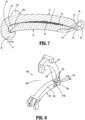
- the second beam 14 has a second clamping surface 32 is in juxtaposed alignment with the first clamping surface 22 when the clip 10 is in the clamped position ( FIG. 7 ).
- the first and second clamping surfaces 22 and 32 may include tissue retention features such as protrusions and/or recesses to minimize slippage of the ligation clip 10 along tissue when the ligation clip 10 is clamped about tissue.
- tissue retention features such as protrusions and/or recesses
- the first and second beams 12, 14 are longitudinally aligned and the clamping surfaces 22, 32 of the first and second beams 12, 14, respectively, face in substantially the same direction. In this position, no strain is placed on the first and second mating features 16, 24, respectively, of the first and second beams 12, 14, respectively.
- the first locking element 18 of the first beam 12 includes a latch member 40 and the second locking element 26 of the second beam 14 includes a latch member receiver 42 that is positioned to receive and engage the latch member 40 to retain the ligation clip 10 in a clamped position ( FIG. 7 ).
- the latch member 40 may be hook-shaped and the latch member receiver 42 may define a channel 42a between the second bosses 28 that directs or guides the latch member 40 into engagement with the latch member receiver 42.
- the first and second locking elements 18 and 26 may assume a variety of different configurations to retain the ligation clip 10 in the clamped position ( FIG. 7 ).
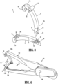
- FIG. 3 illustrates the ligation clip 10 with the first beam 12 separated from the second beam 14.
- the first mating feature 16 of the first beam 12 of the ligation clip 10 is configured to be coupled with the second mating feature 24 of the second beam 14 of the ligation clip 10 to facilitate pivotable movement of the first beam 12 in relation to the second beam 14 between open ( FIG. 1 ) and clamped positions ( FIG. 7 ).
- the first mating feature 16 of the first beam 12 includes a hook portion 44 that defines a semi-cylindrical recess 46 and the second mating feature 24 includes a transverse post 48 that can be received within the semi-cylindrical recess 46 to couple the first beam 12 to the second beam 14.
- the transverse post 48 ( FIG. 5 ) is substantially cylindrical.
- the first end portion 14a of the second beam 14 defines a first through bore 50 that extends through an upper surface of the beam 14 that is contiguous with the second clamping surface 32 and receives the hook portion 44 of the first beam 12.
- the transverse post 48 defines one end of the first through bore 50 and is received within the semi-cylindrical recess 46 of the hook portion 44 of the first mating feature 16 when the hook portion 44 is inserted through the first through bore 50 of the second beam 14 to pivotably secure the first beam 12 to the second beam 14.
- the configuration of the first and second mating features 16 and 24 allows the ligation clip 10 to be positioned in the open position with the first beam 12 in substantial alignment with the second beam 14 without placing any strain on the first and second mating features 16 and 24 of the first and second beams 12, 14 to minimize strain and material creep within the ligation clip 10.
- the second beam 14 of the ligation clip 10 also defines a second through bore 52 that extends between side walls of the second beam 14.
- the second through bore 52 allows a portion of the first end portion 14a of the second beam 14 to flex inwardly upon movement of the ligation clip 10 to the clamped position to facilitate closure of the ligation clip 10.
- the second through bore 52 may have a diamond shape to form a flexible portion 54 ( FIG. 5 ) on the first end 14a of the second beam 14. Alternately, other configurations are envisioned for the second through bore 52, e.g., oval, circular, etc.
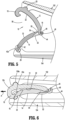
- FIGS. 4-7 illustrate the ligation clip 10 supported in a conventional clip applier 100 as the ligation clip 10 in moved from a partially open position ( FIG. 4 ) to the clamped position ( FIG. 7 ) to apply the ligation clip 10 to tissue.
- the clip applier 100 includes a first jaw 102 and a second jaw 104 that is secured to the first jaw 102 by a pivot member 106.
- the pivot member 106 facilitates pivotal movement of the first jaw 102 in relation to the second jaw 104 between an open position ( FIG. 4 ) and a closed position.
- the jaws 102 and 104 include semi-circular recesses 108a and 108b that receive the first and second bosses 20 and 28 of the first and second beams 12 and 14, respectively, to support the ligation clip 10 between the jaws 102, 104. Receipt of the bosses 20 and 28 within the recesses 108a and 108b secures the ligation clip 10 between the jaws 102 and 104.
- FIGS. 4 and 5 illustrate the ligation clip 10 supported between the first and second jaws 102 and 104 of the clip applier 100 in an open position.
- the bosses 20 are received within the recesses 108a in the jaw 102 of the clip applier 100 and the bosses 28 are received in the recesses 108b in the jaw 104 of the clip applier 100.
- the first clamping surface 22 on the second end portion 12b of the first beam 12 is spaced from the second clamping surface 32 on the second end portion 14b of the second beam 14 such that the first locking element 18 is spaced from the second locking element 26.
- the second ends 12b and 14b of the first and second beams 12 and 14 define a mouth 56 for receiving tissue "T" ( FIG. 7 ) and the flexible portion 54 ( FIG. 5 ) of the first end 14a of the second beam 14 is not compressed such that minimal strain is applied to the first and second beams 12, 14.
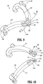
- FIGS. 8-14 illustrate another exemplary embodiment of the disclosed ligation clip shown generally as 200.
- the ligation clip 200 is substantially similar to the ligation clip 10 except for the configuration of the first mating feature 216 on the first beam 212 and the configuration of the second mating feature 224 on the second beam 214. Accordingly, for the sake of brevity, only the first and second mating features 216 and 224 will be described in detail herein.
- FIGS. 8-11 illustrate the ligation clip 200 in the open position with the second end portion of the first beam 212 spaced from the second end portion 214a of the second beam 214 to define a mouth 256 for receiving tissue "T" ( FIG. 14 ).
- the first beam 212 includes a first clamping surface 222 and the second beam 214 includes a second clamping surface 232.
- the first mating feature 216 is formed on the first end 212a of the first beam 212 and includes a body 260 defining a flat surface 262 that is contiguous with the first clamping surface 222.
- the body 260 has a width "W1" ( FIG.
- the body 260 includes a projection 266 that extends downwardly from the flat surface 262 towards the second beam 214.
- the projection 266 is arrow-shaped and includes a retention head 268 that having retention surfaces 268a.
- the flat surface 262 of the first mating feature 216 is positioned in juxtaposed engagement with the flat surface 272 of the second mating feature 224 of the second beam 214.
- the ligation clip 200 is in an open position ( FIG. 8 ) with minimal strain placed on the first and second beams 212, 214.
- the first end of each of the first and second beams 212 and 214 includes a second through bore 278 that extends between side walls of the first and second beams 212 and 214.
- the second through bores 278 allow a portion of the first end portions 212a and 214a of the first and second beams 212 and 214, respectively, to flex inwardly upon movement of the ligation clip 200 towards the clamped position to facilitate closure of the ligation clip 200.
- the first and second through bores 278 may have diamond shapes although other configurations are envisioned, e.g., oval, circular, etc.
- FIG. 12 illustrates the ligation clip 200 supported between the first and second jaws 102 and 104 of the clip applier 100 ( FIG. 4 ) in an open position.
- bosses 220 on the first beam 212 of the ligation clip 200 are received within the recesses 108a in the jaw 102 of the clip applier 100 and the bosses 228 on the second beam 214 of the ligation clip 200 are received in the recesses 108b in the jaw 104 of the clip applier 100.
- the first clamping surface 222 on the second end portion 212b of the first beam 212 is spaced from the second clamping surface 232 on the second end portion 214b of the second beam 214 such that the first locking element 218 is spaced from the second locking element 226.
- minimal strain is placed on the first and second beams 212 and 214.
- FIGS. 13 and 14 illustrate the ligation clip 200 and clip applier 100 ( FIG. 4 ) as the jaws 102 and 104 of the clip applier 100 ( FIG. 4 ) are approximated to move the ligation clip 200 from the open position ( FIG. 12 ) towards the clamped position ( FIG. 14 ).
- the first and second beams 212 and 214 bend at their hinge portions 264 and 274, respectively, such that the clamping surfaces 222 and 232 of the first and second beams 212 and 214 move into juxtaposed alignment.
- the first locking element 218 of the first beam 212 moves through the channel 242a ( FIG.
- tissue "T” is clamped between the first and second clamping surfaces 222 and 232 of the first and second beams 212 and 214, respectively.
- first and second beams 212, 214 are deformed about their hinge portions 264 and 274, respectively, to generate a force in the beams 212 and 214 tending to urge the beams 212 and 214 to the open position ( FIG. 12 ).
- This force helps to retain the first and second locking elements 218 and 226 engaged with each other to retain the ligation clip 200 in the clamped position.
- the beams 212, 214 of the ligation clip 200 are illustrated as being coupled together during delivery of the ligation clip 200 to a surgical site, it is envisioned that the first and second beams 212, 214 (as well as beams 12, 14 of ligation clip 10) could be delivered to a surgical site as separate components and coupled together upon delivery to the surgical site prior to being moved to the clamped position. This would allow the first and second beams 212, 214 to be delivered to the surgical site with the first beam 212 longitudinally aligned with the second beam 214 (such as shown in FIG. 1 in regard to ligation clip 10) to facilitate delivery of the ligation clip 200 through a small diameter cannula or incision.
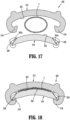
- FIGS. 15-18 illustrate another exemplary embodiment of the disclosed ligation clip shown generally as 300.
- the ligation clip 300 is substantially similar to the ligation clip 10 ( FIG. 1 ) and 200 ( FIG. 8 ) except for the configuration of the first mating feature 316 on the first beam 312 and the configuration of the second mating feature 324 on the second beam 314. Accordingly, for the sake of brevity, only the first and second mating features 316 and 324 will be described in detail herein.
- FIG. 15 illustrates the ligation clip 300 in the open position with the first beam 312 spaced from the second beam 314.
- the first and second beams 312 and 314, respectively, of the ligation clip 300 are not pivotably coupled to each other at one end. Rather, the first and second beams 312 and 314 are moved to the closed position in parallel orientation to clamp tissue "T" ( FIG. 18 .
- the first beam 312 of the ligation clip 300 includes a first clamping surface 322 and the second beam 314 of the ligation clip 300 includes a second clamping surface 332.
- first locking elements 318 move through the channels 342a of the latch member receivers 342, contact between each of the first locking elements 318 and a respective one of the second locking elements 326 biases the first locking elements 318 outwardly to allow the first locking elements 318 to pass over and snap into engagement with the locking member receiver 342 ( FIG. 18 ). Engagement between the first and second locking elements 318 and 326 secures the first beam 312 to the second beam 314 in the clamped position.
- the first and second beams 312, 314 can be delivered to a surgical site independently with the beams 312, 314 in longitudinal alignment to facilitate delivery of the ligation clip through a small diameter incision or trocar.
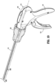
- FIGS. 19-24 illustrate a surgical clip applier, shown generally as clip applier 500, that can be used to apply a surgical clip, e.g., ligation clip 10 ( FIG. 1 ), to tissue "T".
- the clip applier 500 includes a handle assembly 510, an elongate shaft 512 that defines a longitudinal axis "X", and a tool assembly 514 ( FIG. 20 ).
- the handle assembly 510 includes a stationary handle 516 and a movable trigger 518 that is movable from a non-compressed position ( Fig. 19 ) toward the stationary handle 516 to a compressed position to operate the tool assembly 514 ( FIG. 20 ).
- the elongate shaft 512 includes a proximal portion that is supported by a scalloped rotation knob 520.
- the scalloped rotation knob 520 is supported on the handle assembly 510 for rotation such that rotation of the rotation knob 520 about the longitudinal axis "X" causes rotation of the elongate shaft 512 and tool assembly 514 in relation to the handle assembly 510 about the longitudinal axis "X".
- the elongate shaft 512 defines a stepped channel 524 that extends from the handle assembly 510 and receives the tool assembly 514.
- the stepped channel 524 has a first portion 524a and a second portion 524b having a width that is smaller than the width of the first portion 524a.
- the tool assembly 514 is received within the first portion 524a of the stepped channel 524 and is movable from a retracted position within the stepped channel 524 ( FIG. 21 ) to an advanced position ( FIG. 22 ) extending from a distal end of the stepped channel 524.
- the ligation clip 10 extends into and is partially received within the second portion 524b of the stepped channel 524.
- Engagement between the ligation clip 10 and walls defining the second portion 524b of the stepped channel 524 maintains the orientation of the ligation clip 10 within the stepped channel 524 and on the tool assembly 514 as the tool assembly 514 is moved within the stepped channel 524 from its retracted position to its advanced position.
- FIGS. 20 and 21 illustrate the tool assembly 514 which includes a first jaw 530, a second jaw 532, and an actuator rod 534.
- the first jaw 530 supports the second jaw 532 and is movable longitudinally within the first portion 524a of the stepped channel 524 between its retracted position ( FIG. 21 ) and its advanced position ( FIG. 22 ).
- the first jaw 530 is supported on a distal end portion of a rail 538 that extends from the handle assembly 510 through the elongate shaft 512.
- the rail 538 defines a channel 540 that receives the actuator rod 534.
- the stationary jaw 530 includes side walls 542 that define a cavity 544 between the side walls 542 and a bore 546 in each of the side walls 542.
- the cavity 544 communicates with the channel 540.
- the first jaw 530 includes a distal portion 548 that includes spaced arms 550. Each of the spaced arms 550 defines a concavity 552 that receives the bosses 28 on the second beam 14 of the ligation clip 10 to support the ligation clip 10 on the first jaw 530.
- the second jaw 532 includes a first end portion 554 that includes spaced hubs 556. Each of the spaced hubs 556 supports a pivot member 556a that is received within one of the bores 546 of the first jaw 530 to pivotably couple the second jaw 532 to the first jaw 530.
- the second jaw 532 also includes an arm 558 that extends from the first portion 554 of the second jaw 532 to a second portion 560 of the second jaw 532.
- the second portion 560 includes a pair of spaced support members 562 that define concavities 564. The concavities 564 receive the bosses 20 of the ligation clip 10 to support the first beam 12 of the ligation clip 10 on the second jaw 532 ( FIG. 21 ).
- the actuator rod 534 is movable within the channel 540 of the rail 538 and the cavity 544 of the stationary jaw 530 between an advanced position ( FIG. 21 ) and a retracted position ( FIG. 25 ) and includes a distal portion 566 that has a forked member 568.
- the forked member 568 includes two tines 568a. Each of the tines 568a is coupled to one of the spaced hubs 556 of the second jaw 532 by a flexible coupling member 570.
- the connection point between the flexible coupling member 570 and the spaced hubs 556 is positioned outwardly of a transverse axis defined by the pivot members 556a of the second jaw 532.
- the tines 568a cause the second jaw 532 to pivot about the transverse axis defined by the pivot member 556a to pivot the second jaw 532 in relation to the first jaw 530 from on open position ( FIG. 21 ) to a clamped position ( FIG. 25 ).
- the clip applier 500 ( FIG. 19 ) is used by a clinician to position a ligation clip 10 onto tissue endoscopically
- the elongate shaft 512 and the tool assembly 514 are inserted through a cannula and/or an incision in a patient's body to access the surgical site.
- the tool assembly 514 is inserted through the cannula
- the tool assembly 514 is in the open position.
- the first jaw 530 is longitudinally aligned with the second jaw 532 to facilitate placement through a small diameter incision or cannula.
- the ligation clip 10 is supported within the first and second jaws 530, 532 in the fully open position.
- the beams 12, 14 are supported on the first and second jaws 530 and 532 and such that the clamping surface 22, 32 of the first and second beams 12, 14, respectively, of the ligation clip 10 are longitudinally aligned and face in substantially the same direction.
- the bosses 28 of the second beam 14 are received in the concavities 552 of the second jaw 14 and the bosses 20 received in the concavities 564 of the second jaw 53.
- the width of the ligation clip 10 is minimized to facilitate receipt of the ligation clip 10 within a reduced diameter elongate shaft 512 and/or delivery of the ligation clip 10 through a small diameter cannula and/or incision.
- the ligation clip 10 is in a relaxed condition such that minimal strain is placed on the clip 10 prior to application of the clip 10 to tissue "T" ( FIG. 25 ).
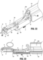
- FIGS. 22 and 23 illustrate the clip applier 500 with the tool assembly 514 moved to the advanced position extended from the elongate shaft 512.
- the tool assembly 514 is moved to the advanced position in the direction indicated by arrow "A" via operation of the trigger assembly 510.
- the first jaw 530 is moved through the distal end of the elongate shaft 512 to expose the ligation clip 10 in the open position.
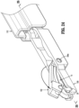
- FIGS. 24 and 25 illustrate the distal portion of the clip applier 500 ( FIG. 19 ) as the tool assembly 514 is actuated to apply the ligation clip 10 about the tissue "T".
- the actuator rod 534 FIG. 25
- the flexible coupling members 570 is moved from its advanced position to its retracted position in the direction indicated by arrows "B” in FIG. 25 to move the flexible coupling members 570 about the transverse pivot axis defined by the pivot members 556a to pivot the second jaw 532 in the direction indicated by arrows "C”.
- the first beam 12 of the ligation clip 10 is pivoted towards the second beam 14 to move the first locking element 18 of the first beam 12 into latching engagement with the second locking element 26 of the second beam 14 to retain the ligation clip 10 in the clamped position.
- the ligation clips 200, and 300 can be applied to tissue using the clip applier 500.
- the ligation clips 200, 300 can be delivered to a surgical site with the first and second beams separated from each other, wherein the first and second beams 12, 14 are joined immediately prior to application of the ligation clip 10, 200, 300 to tissue.
- the clip applier 500 may be provided to deliver clips 10, 200, 300 to jaws of the clip applier with the first and second beams separated from each other so that the width of the clip is minimized to facilitate receipt of the clip within a small diameter shaft and to minimize strain on the ligation clip or portions of the ligation clip. As discussed above, this prevents degradation of the condition and/or the performance of the ligation clip during storage of the clip within the clip applier and/or during delivery of the ligation clip to the surgical site.
- the exemplary aspects of the ligation clips described in this application can be formed from resilient polymeric materials including. Other materials of construction are also envisioned.
Landscapes
- Health & Medical Sciences (AREA)
- Surgery (AREA)
- Life Sciences & Earth Sciences (AREA)
- Heart & Thoracic Surgery (AREA)
- Nuclear Medicine, Radiotherapy & Molecular Imaging (AREA)
- Vascular Medicine (AREA)
- Engineering & Computer Science (AREA)
- Biomedical Technology (AREA)
- Reproductive Health (AREA)
- Medical Informatics (AREA)
- Molecular Biology (AREA)
- Animal Behavior & Ethology (AREA)
- General Health & Medical Sciences (AREA)
- Public Health (AREA)
- Veterinary Medicine (AREA)
- Surgical Instruments (AREA)
Claims (3)
- Ligaturklammer (10), umfassend:einen ersten Balken (12) mit einem ersten Endabschnitt (12a), einem zweiten Endabschnitt (12b) und einer ersten Klemmfläche (22), die zwischen dem ersten und zweiten Endabschnitt (12a, 12b) positioniert ist, wobei der erste Endabschnitt (12a) ein erstes Passungsmerkmal (16) einschließt und der zweite Endabschnitt (12b) eine erste Verriegelungsstruktur (18) einschließt;einen zweiten Balken (14) mit einem ersten Endabschnitt (14a), einem zweiten Endabschnitt (14b) und einer zweiten Klemmfläche (32), die zwischen dem ersten und dem zweiten Endabschnitt (14a, 14b) angeordnet ist, wobei der erste Endabschnitt (14a) des zweiten Balkens (14) ein zweites Passungsmerkmal (24) einschließt und der zweite Endabschnitt (14b) des zweiten Balkens (14) eine zweite Verriegelungsstruktur (26) einschließt, wobei das zweite Passungsmerkmal (24) so ausgebildet ist, dass es mit dem ersten Passungsmerkmal (16) gekoppelt werden kann, um den ersten Balken (12) mit dem zweiten Balken (14) zu koppeln, wobei der erste Balken (12) in Bezug auf den zweiten Balken (14) beweglich ist, um die Ligaturklammer (10) von einer offenen Position in eine geklemmte Position zu bewegen, wobei die erste Verriegelungsstruktur (18) so ausgebildet ist, dass sie mit der zweiten Verriegelungsstruktur (26) in Eingriff kommt, um die Ligaturklammer (10) in der geklemmten Position zu sichern,wobei das erste Passungsmerkmal (16) und die erste Verriegelungsstruktur (18) jeweils ein hakenförmiges Riegelelement (40) einschließen und das zweite Passungsmerkmal (24) und die zweite Verriegelungsstruktur (26) jeweils eine Riegelelementaufnahme (42) einschließen, wobei die hakenförmigen Riegelelemente (40) in Eingriff mit den jeweiligen Riegelelementaufnahmen (42) gebracht werden können, um die Ligaturklammer (10) in der geklemmten Position zu sichern; wobei das erste Passungsmerkmal (16) einen Hakenabschnitt (44) einschließt, der eine halbzylindrische Aussparung (46) definiert, und das zweite Passungsmerkmal (24) einen Querpfosten (48) einschließt, der in der halbzylindrischen Aussparung (46) aufgenommen ist, um den ersten Balken (12) schwenkbar mit dem zweiten Balken (14) zu verbinden;
wobei der erste Endabschnitt (14a) des zweiten Balkens (14) eine erste Durchgangsbohrung (50) definiert, die den Hakenabschnitt (44) aufnimmt, wobei der Querpfosten (48) ein Ende der Durchgangsbohrung (50) definiert und wobei der zweite Balken (14) Seitenwände einschließt,dadurch gekennzeichnet, dass das erste Ende des zweiten Balkens (14) eine zweite Durchgangsbohrung (52) definiert, die zwischen den Seitenwänden des zweiten Balkens (14) verläuft, wobei die zweite Durchgangsbohrung (52) einen flexiblen Abschnitt bildet, der so positioniert ist, dass er mit dem ersten Balken (12) in Eingriff kommt, wenn die Ligaturklammer (10) von der offenen Position in Richtung der geklammerten Position bewegt wird, um die Ligaturklammer (10) in Richtung der offenen Position zu drücken. - Ligaturklammer (10) nach Anspruch 1, wobei der erste Balken (12) erste Vorsprünge (20) einschließt, die von gegenüberliegenden Seiten des zweiten Endabschnitts (12b) des ersten Balkens (12) ausgehen, und der zweite Balken (14) zweite Vorsprünge (28) einschließt, die von gegenüberliegenden Seiten des zweiten Endabschnitts (14b) des zweiten Balkens (14) ausgehen.
- Ligaturklammer (10) nach einem der vorstehenden Ansprüche, wobei das erste Passungsmerkmal (16) so angepasst ist, dass es lösbar mit einer ersten Passungsstruktur verbunden werden kann.
Priority Applications (1)
| Application Number | Priority Date | Filing Date | Title |
|---|---|---|---|
| EP25168535.0A EP4555950A3 (de) | 2019-07-02 | 2020-06-26 | Mehrteiliger ligaturclip |
Applications Claiming Priority (2)
| Application Number | Priority Date | Filing Date | Title |
|---|---|---|---|
| US201962869584P | 2019-07-02 | 2019-07-02 | |
| US16/866,649 US11707282B2 (en) | 2019-07-02 | 2020-05-05 | Multi-piece ligation clip |
Related Child Applications (2)
| Application Number | Title | Priority Date | Filing Date |
|---|---|---|---|
| EP25168535.0A Division-Into EP4555950A3 (de) | 2019-07-02 | 2020-06-26 | Mehrteiliger ligaturclip |
| EP25168535.0A Division EP4555950A3 (de) | 2019-07-02 | 2020-06-26 | Mehrteiliger ligaturclip |
Publications (3)
| Publication Number | Publication Date |
|---|---|
| EP3760140A2 EP3760140A2 (de) | 2021-01-06 |
| EP3760140A3 EP3760140A3 (de) | 2021-02-24 |
| EP3760140B1 true EP3760140B1 (de) | 2025-05-14 |
Family
ID=71266311
Family Applications (2)
| Application Number | Title | Priority Date | Filing Date |
|---|---|---|---|
| EP20182582.5A Active EP3760140B1 (de) | 2019-07-02 | 2020-06-26 | Mehrteilige ligaturklammer |
| EP25168535.0A Pending EP4555950A3 (de) | 2019-07-02 | 2020-06-26 | Mehrteiliger ligaturclip |
Family Applications After (1)
| Application Number | Title | Priority Date | Filing Date |
|---|---|---|---|
| EP25168535.0A Pending EP4555950A3 (de) | 2019-07-02 | 2020-06-26 | Mehrteiliger ligaturclip |
Country Status (3)
| Country | Link |
|---|---|
| US (3) | US11707282B2 (de) |
| EP (2) | EP3760140B1 (de) |
| CN (1) | CN112168272B (de) |
Families Citing this family (5)
| Publication number | Priority date | Publication date | Assignee | Title |
|---|---|---|---|---|
| US11707282B2 (en) | 2019-07-02 | 2023-07-25 | Covidien Lp | Multi-piece ligation clip |
| US12114866B2 (en) | 2020-03-26 | 2024-10-15 | Covidien Lp | Interoperative clip loading device |
| KR20240006062A (ko) * | 2021-05-07 | 2024-01-12 | 텔리플렉스 메디컬 인코포레이티드 | 외과용 클립을 언래칭하기 위한 장치 및 방법 |
| CN114403977B (zh) * | 2022-01-29 | 2024-01-02 | 苏州英途康医疗科技有限公司 | 一种结扎夹和夹仓装置 |
| CN116919516A (zh) * | 2022-03-31 | 2023-10-24 | 江苏风和医疗器材股份有限公司 | 施夹钳 |
Citations (1)
| Publication number | Priority date | Publication date | Assignee | Title |
|---|---|---|---|---|
| WO2019099462A1 (en) * | 2017-11-14 | 2019-05-23 | Teleflex Medical Incorporated | Surgical clip |
Family Cites Families (133)
| Publication number | Priority date | Publication date | Assignee | Title |
|---|---|---|---|---|
| US3040749A (en) | 1958-04-07 | 1962-06-26 | Hugh W Payton | Umbilical cord clamp |
| US3247852A (en) * | 1963-10-10 | 1966-04-26 | Hollister Inc | Umbilical cord clamp |
| US3439523A (en) | 1964-03-30 | 1969-04-22 | Peter B Samuels | Hemostatic clip constructions |
| BE654195A (de) | 1964-10-09 | 1965-02-01 | ||
| US3713533A (en) | 1971-04-28 | 1973-01-30 | Codman & Shurtleff | Hemostatic clip holder |
| US4076120A (en) | 1976-12-10 | 1978-02-28 | American Hospital Supply Corporation | Cartridge for holding hemostatic clips |
| US4146130A (en) | 1977-04-08 | 1979-03-27 | Samuels Peter B | Hemostatic clip, clip applicator and cartridge therefor |
| US4187712A (en) | 1977-04-08 | 1980-02-12 | Samuels Peter B | Hemostatic clip applicator |
| US4212390A (en) | 1977-10-20 | 1980-07-15 | Propper Manufacturing Co., Inc. | Wound clip rack |
| US4212303A (en) | 1978-07-17 | 1980-07-15 | Hollister Incorporated | Umbilical cord clamp |
| US4390019A (en) | 1979-02-28 | 1983-06-28 | Leveen Harry H | Blood vessel clamp |
| US4227730A (en) * | 1979-05-29 | 1980-10-14 | Baxter Travenol Laboratories, Inc. | Gripper member for retention of a plastic tube |
| US4418694A (en) | 1979-06-18 | 1983-12-06 | Ethicon, Inc. | Non-metallic, bio-compatible hemostatic clips |
| US4294355A (en) | 1979-12-06 | 1981-10-13 | Ethicon, Inc. | Cartridge for hemostatic clips |
| US4344531A (en) | 1980-09-08 | 1982-08-17 | Edward Weck & Company, Inc. | Hemostatic clip cartridge |
| US4346869A (en) | 1981-03-12 | 1982-08-31 | Macneill Robert L | Tube clamp |
| US4412617A (en) | 1981-07-20 | 1983-11-01 | Ethicon, Inc. | Ligating clip package |
| US4361229A (en) | 1981-08-03 | 1982-11-30 | Ethicon, Inc. | Cartridge for hemostatic clips |
| US4449531A (en) | 1981-08-27 | 1984-05-22 | Ethicon, Inc. | Non-metallic, bio-compatible hemostatic clips with interlocking latch means |
| US4550729A (en) | 1981-08-27 | 1985-11-05 | Ethicon, Inc. | Non-metallic, bio-compatible hemostatic clips with interlocking latch means |
| US4485953A (en) | 1982-04-05 | 1984-12-04 | Senco Products, Inc. | Surgical stapling instrument and cartridge therefor |
| US4487205A (en) | 1982-04-26 | 1984-12-11 | Ethicon, Inc. | Non-metallic, bio-compatible hemostatic clips |
| US4696396A (en) | 1985-12-19 | 1987-09-29 | Samuels Peter B | Hemostatic clip cartridge |
| US4726372A (en) | 1986-09-19 | 1988-02-23 | Metatech Corporation | Hemostatic clip |
| US4834096A (en) | 1987-10-26 | 1989-05-30 | Edward Weck Incorporated | Plastic ligating clips |
| US4971198A (en) | 1988-04-18 | 1990-11-20 | Edward Weck Incorporated | Hemostatic clip and cartridge assembly |
| US4942886A (en) | 1989-02-22 | 1990-07-24 | Timmons John W | External incontinency device |
| US5062846A (en) | 1989-03-28 | 1991-11-05 | Edward Weck Incorporated | Penetrating plastic ligating clip |
| US4972949A (en) | 1989-09-26 | 1990-11-27 | Horizon Surgical, Inc. | Hemostatic clip holder for small clips |
| US4936447A (en) | 1989-09-26 | 1990-06-26 | Horizon Surgical Inc. | Hemostatic clip holder |
| US5100416A (en) | 1989-10-17 | 1992-03-31 | Edward Weck Incorporated | Ligating clip applying instrument |
| US4961499A (en) | 1990-01-04 | 1990-10-09 | Pilling Co. | Hemostatic clip cartridge |
| US5046624A (en) | 1990-08-13 | 1991-09-10 | Murphy Susan A | Surgical instrument stand |
| US5050272A (en) | 1990-10-16 | 1991-09-24 | Anago, Inc. | Closure member for an ice bag |
| US5046611A (en) | 1990-10-22 | 1991-09-10 | Edward Weck Incorporated | Hemostatic clip cartridge |
| US5201416A (en) | 1990-10-22 | 1993-04-13 | Edward Weck Incorporated | Hemostatic clip cartridge |
| US5423831A (en) | 1991-01-24 | 1995-06-13 | Nates; Colin | Clamp |
| US5411481A (en) * | 1992-04-08 | 1995-05-02 | American Cyanamid Co. | Surgical purse string suturing instrument and method |
| US5279416A (en) | 1992-06-05 | 1994-01-18 | Edward Weck Incorporated | Ligating device cartridge with separable retainer |
| US5285556A (en) * | 1992-12-14 | 1994-02-15 | Shorin Joseph E | Integral polymeric clamp |
| US5403327A (en) | 1992-12-31 | 1995-04-04 | Pilling Weck Incorporated | Surgical clip applier |
| US5462555A (en) | 1993-12-30 | 1995-10-31 | United States Surgical Corporation | Umbilical cord clip and applicator |
| US5697942A (en) | 1994-07-31 | 1997-12-16 | Palti; Yoram | Internal vascular clamp |
| US5908430A (en) | 1995-06-07 | 1999-06-01 | Appleby; Timothy | Easy loading hemostatic clip and cartridge |
| US5564262A (en) | 1995-07-20 | 1996-10-15 | Ethicon, Inc. | Ligaclip loading machine and process |
| US5609599A (en) * | 1995-07-27 | 1997-03-11 | Levin; John M. | Leak clip |
| US5713912A (en) | 1995-08-30 | 1998-02-03 | Stress Management, Inc. | Ligating clip having ramp-shaped vessel clamping members and tool for applying same |
| US5676676A (en) | 1995-08-30 | 1997-10-14 | Porter; Wayne | Ligating clip having ramp-shaped vessel-clamping members |
| US5846255A (en) | 1996-01-31 | 1998-12-08 | Casey Medical Products Limited | Surgical clip |
| FR2751863B1 (fr) | 1996-08-01 | 1999-01-22 | Vitalitec International | Support de clips hemostatiques |
| GB9707204D0 (en) | 1997-04-09 | 1997-05-28 | Price Invena Aps | Clamping and cutting devices |
| US6044971A (en) | 1997-10-10 | 2000-04-04 | United States Surgical Corporation | Clip cartridge |
| US5921991A (en) | 1997-10-23 | 1999-07-13 | Biomax Technologies Inc. | Multi-colored umbilical cord clamp |
| JP2000131620A (ja) | 1998-10-27 | 2000-05-12 | Olympus Optical Co Ltd | 望遠鏡 |
| US6228097B1 (en) | 1999-01-22 | 2001-05-08 | Scion International, Inc. | Surgical instrument for clipping and cutting blood vessels and organic structures |
| US6217590B1 (en) | 1999-01-22 | 2001-04-17 | Scion International, Inc. | Surgical instrument for applying multiple staples and cutting blood vessels and organic structures and method therefor |
| DE19903752C1 (de) | 1999-01-30 | 2000-03-30 | Aesculap Ag & Co Kg | Magazin zur Aufnahme von Clips |
| GB2353710A (en) | 1999-08-06 | 2001-03-07 | Henleys Medical Supplies Ltd | Umbilical cord clamp |
| IL132913A (en) | 1999-11-14 | 2004-09-27 | Porat Michael | Device and method for clamping and cutting a flexible deformable tube |
| US6391035B1 (en) | 2000-03-24 | 2002-05-21 | Timothy Appleby | Hemostatic clip removal instrument |
| US6419682B1 (en) | 2000-03-24 | 2002-07-16 | Timothy Appleby | Hemostatic clip cartridge |
| US6349727B1 (en) | 2000-05-25 | 2002-02-26 | Pos-T-Vac, Inc. | Penile clamp for inhibiting incontinence |
| US6273253B1 (en) | 2000-07-07 | 2001-08-14 | Vitalitec International, Inc. | Cartridge and system for holding and applying clips |
| US20020046961A1 (en) | 2000-10-19 | 2002-04-25 | Scion International | Surgical clip holder and method therefor |
| DE10116168A1 (de) | 2001-03-31 | 2001-11-29 | Joachim Heinzl | Verfahren und Einrichtung zum Klippsen mit dem Endoskop |
| US20020177863A1 (en) | 2001-05-24 | 2002-11-28 | Mandel Stanley R. | Surface treated ligating clip |
| US6824547B2 (en) | 2001-07-13 | 2004-11-30 | Pilling Weck Incorporated | Endoscopic clip applier and method |
| US20030069589A1 (en) | 2001-10-09 | 2003-04-10 | Small George H. | Umbilical cord clamp and methods of using same |
| US20040199178A1 (en) | 2001-10-09 | 2004-10-07 | Small George H. | Umbilical cord clamp and methods of using same |
| US7211091B2 (en) | 2002-08-27 | 2007-05-01 | Pilling Weck Incorporated | Fingertip-actuated surgical clip applier and related methods |
| US6880699B2 (en) | 2002-08-27 | 2005-04-19 | Pilling Weck Incorporated | Cartridge for holding asymmetric surgical clips |
| US7131977B2 (en) | 2002-08-27 | 2006-11-07 | Pilling Weck Incorporated | Apparatus and method for removing a clip |
| US6863675B2 (en) | 2002-09-20 | 2005-03-08 | Pilling Weck Incorporated | Ligating clip with integral penetrating hook |
| US7052504B2 (en) | 2002-11-19 | 2006-05-30 | Teleflex Incorporated | Automated-feed surgical clip applier and related methods |
| US7211092B2 (en) | 2002-11-19 | 2007-05-01 | Pilling Weck Incorporated | Automated-feed surgical clip applier and related methods |
| WO2004080290A2 (en) | 2003-03-11 | 2004-09-23 | Tyco Healthcare Group, Lp | Clip applying apparatus with angled jaw |
| US7144402B2 (en) | 2003-06-16 | 2006-12-05 | Synovis Life Technologies, Inc. | Vascular clamp |
| US7326223B2 (en) | 2004-01-22 | 2008-02-05 | Teleflex Medical Incorporated | Ligating clip with integral cutting guide |
| US7316696B2 (en) | 2004-01-22 | 2008-01-08 | Teleflex Medical Incorporated | Ligating clip with integral interlocking latch mechanism |
| US20050165423A1 (en) | 2004-01-23 | 2005-07-28 | Pilling Weck Incorporated | Ligating clip with integral tissue-securing mechanism |
| US7001412B2 (en) | 2004-01-28 | 2006-02-21 | Pilling Weck Incorporated | Surgical clip with integral suture-securing mechanism |
| US7585304B2 (en) | 2004-02-02 | 2009-09-08 | Teleflex Medical Incorporated | Endoscopic clip applying apparatus with improved aperture for clip release and related method |
| CN1925810B (zh) | 2004-03-07 | 2010-11-10 | 辛迪思有限公司 | 容置器和支架系统 |
| US7452368B2 (en) | 2004-09-15 | 2008-11-18 | Ethicon, Inc. | System for holding surgical fasteners |
| US20060124485A1 (en) | 2004-12-10 | 2006-06-15 | Kennedy Daniel L | Enhanced visibility cartridge with improved retainer |
| US20060217749A1 (en) | 2005-03-24 | 2006-09-28 | Pilling Weck Incorporated | Reduced closure force ligating clip |
| DE102005045006B3 (de) | 2005-09-21 | 2007-01-04 | Cardiomedical Gmbh | Behältnis zur Aufnahme von Klammern |
| US20070083218A1 (en) | 2005-10-12 | 2007-04-12 | A Morris Steven | Coated ligating clip |
| US20070118161A1 (en) | 2005-11-22 | 2007-05-24 | Kennedy Daniel L | Non-snag polymer ligating clip |
| US9480480B2 (en) | 2005-12-22 | 2016-11-01 | Albert N. Santilli | Vascular and intestinal occlusion |
| US9486225B2 (en) | 2005-12-22 | 2016-11-08 | Robert E. Michler | Exclusion of the left atrial appendage |
| US8328458B2 (en) | 2007-07-20 | 2012-12-11 | Twin Bay Medical, Inc. | Sanitary clamp |
| US8512362B2 (en) | 2007-11-05 | 2013-08-20 | Usgi Medical Inc. | Endoscopic ligation |
| US8042687B2 (en) | 2007-12-14 | 2011-10-25 | Vesocclude Medical Llc | Hemostatic clip cartridge |
| US9445820B2 (en) | 2007-12-31 | 2016-09-20 | Teleflex Medical Incorporated | Ligation clip with flexible clamping feature |
| DE102008018158A1 (de) | 2008-04-10 | 2009-10-15 | Aesculap Ag | Ligaturklammermagazin und Lagerkörper zur Verwendung in diesem |
| DE102009035756A1 (de) | 2009-07-24 | 2011-01-27 | Aesculap Ag | Clipträgervorrichtung |
| US8425515B2 (en) | 2009-10-30 | 2013-04-23 | Depuy Spine, Inc. | Bone graft loading instruments and methods of connecting a bone graft to a bone plate |
| US10136898B2 (en) | 2010-03-09 | 2018-11-27 | Teleflex Medical Incorporated | Narrow profile surgical ligation clip |
| US20110224700A1 (en) | 2010-03-09 | 2011-09-15 | Teleflex Medical Incorporated | Narrow Profile Surgical Ligation Clip |
| US20110295291A1 (en) | 2010-05-28 | 2011-12-01 | Dean Trivisani | Novel Vascular Clamp |
| US10335157B2 (en) | 2010-10-02 | 2019-07-02 | Covidien Lp | Asymmetrical surgical clip with penetrating lock, non-slip clamping surface, severable hinge, hinge boss and pivoting applicator tip |
| US20120226291A1 (en) | 2011-03-04 | 2012-09-06 | Jenkins Clinic, Inc. | Surgical Ligation Clip and Applicator Device |
| EP2688492A4 (de) | 2011-03-21 | 2015-07-08 | Univ Tulane | Ablösbare mehrteilige klemmwerkzeuge sowie verfahren zu ihrer herstellung und anwendung |
| KR20140015514A (ko) | 2011-04-26 | 2014-02-06 | 바이탈리텍 인터내셔널, 아이엔씨. | 통합 잠금 시스템을 구비한 수술용 패스너를 위한 카트리지 |
| US9271737B2 (en) | 2011-09-15 | 2016-03-01 | Teleflex Medical Incorporated | Automatic surgical ligation clip applier |
| EP2755578A2 (de) | 2011-09-15 | 2014-07-23 | Teleflex Medical Incorporated | Manueller chirurgischer ligationsclipapplikator |
| WO2013059826A1 (en) | 2011-10-20 | 2013-04-25 | Atsina Surgical, Llc | Ligation clip |
| DE102011056821A1 (de) | 2011-12-21 | 2013-06-27 | Aesculap Ag | Medizinische Clipträgervorrichtung |
| US9282972B1 (en) | 2012-10-14 | 2016-03-15 | Innovative Urololy, Llc | Surgical clips with penetrating locking mechanism and non-slip clamping surfaces |
| US10226273B2 (en) | 2013-03-14 | 2019-03-12 | Ethicon Llc | Mechanical fasteners for use with surgical energy devices |
| WO2016081822A1 (en) | 2014-11-21 | 2016-05-26 | Novate Medical Technologies, Llc | Multi-component detachable cutting and clamping tool and methods of using same |
| CN106264647A (zh) | 2015-06-04 | 2017-01-04 | 上海林超医疗设备科技有限公司 | 具有开夹功能的施夹钳 |
| WO2016205343A1 (en) | 2015-06-16 | 2016-12-22 | Nanova Biomaterials, Inc. | Anti-migration surgical ligation clip |
| CN204839635U (zh) | 2015-06-19 | 2015-12-09 | 江西圣济药业有限公司 | 一种自定位型脐带夹 |
| CN204765788U (zh) * | 2015-07-03 | 2015-11-18 | 桐庐洲济医疗器械有限公司 | 一次性结扎夹 |
| WO2017017587A2 (en) * | 2015-07-24 | 2017-02-02 | Cliptip Medical Ltd | Thickness-adjustable hemostatic clips, clip appliers, and applications thereof |
| EP3328295B1 (de) | 2015-07-30 | 2021-05-05 | Teleflex Medical Incorporated | Schnappbare chirurgische clipkassette |
| CN105078536A (zh) | 2015-08-26 | 2015-11-25 | 施青青 | 一种双联组织夹及施夹器 |
| JP2018537168A (ja) * | 2015-11-20 | 2018-12-20 | クリップティップ メディカル リミテッド | 外科クリップ及びその留置制御 |
| US10258345B2 (en) | 2016-05-25 | 2019-04-16 | Geoff Brown | Surgical ligation clip |
| CA3032824C (en) | 2016-08-03 | 2021-04-27 | Teleflex Medical Incorporated | Surgical ligation clip |
| CN206197995U (zh) * | 2016-08-29 | 2017-05-31 | 张大宏 | 强力防脱型止血夹 |
| US11534177B2 (en) | 2017-03-21 | 2022-12-27 | Teleflex Medical Incorporated | Flexible stabilizing member for a clip applier |
| WO2018175610A1 (en) | 2017-03-21 | 2018-09-27 | Teleflex Medical Incorporated | Surgical clip and clip applier |
| JP6876821B2 (ja) | 2017-03-21 | 2021-05-26 | テレフレックス メディカル インコーポレイテッド | 交換可能な先端部を備えたクリップアプライヤ |
| US11266408B2 (en) | 2017-03-21 | 2022-03-08 | Teleflex Medical Incorporated | Clip applier having stabilizing member |
| US10722235B2 (en) * | 2017-05-11 | 2020-07-28 | Covidien Lp | Spring-release surgical clip |
| USD808522S1 (en) | 2017-07-11 | 2018-01-23 | Vesolock Medical, Llc | Latching ends of a polymer ligating clip |
| US20190133590A1 (en) | 2017-11-03 | 2019-05-09 | Covidien Lp | Ligation clip with controlled tissue compression |
| US20190159782A1 (en) | 2017-11-28 | 2019-05-30 | Covidien Lp | Surgical ligation clip with tissue stop member |
| US20190223874A1 (en) | 2018-01-24 | 2019-07-25 | Covidien Lp | Ligation clip with tissue retention features |
| US11707282B2 (en) | 2019-07-02 | 2023-07-25 | Covidien Lp | Multi-piece ligation clip |
-
2020
- 2020-05-05 US US16/866,649 patent/US11707282B2/en active Active
- 2020-06-23 CN CN202010579826.3A patent/CN112168272B/zh active Active
- 2020-06-26 EP EP20182582.5A patent/EP3760140B1/de active Active
- 2020-06-26 EP EP25168535.0A patent/EP4555950A3/de active Pending
-
2023
- 2023-06-27 US US18/214,761 patent/US12285176B2/en active Active
-
2025
- 2025-03-28 US US19/093,738 patent/US20250221716A1/en active Pending
Patent Citations (1)
| Publication number | Priority date | Publication date | Assignee | Title |
|---|---|---|---|---|
| WO2019099462A1 (en) * | 2017-11-14 | 2019-05-23 | Teleflex Medical Incorporated | Surgical clip |
Also Published As
| Publication number | Publication date |
|---|---|
| US20210000474A1 (en) | 2021-01-07 |
| US12285176B2 (en) | 2025-04-29 |
| US20250221716A1 (en) | 2025-07-10 |
| US11707282B2 (en) | 2023-07-25 |
| EP3760140A3 (de) | 2021-02-24 |
| EP3760140A2 (de) | 2021-01-06 |
| CN112168272B (zh) | 2026-03-24 |
| US20230338039A1 (en) | 2023-10-26 |
| EP4555950A3 (de) | 2025-07-30 |
| CN112168272A (zh) | 2021-01-05 |
| EP4555950A2 (de) | 2025-05-21 |
Similar Documents
| Publication | Publication Date | Title |
|---|---|---|
| EP3760140B1 (de) | Mehrteilige ligaturklammer | |
| US10130373B2 (en) | Automatic surgical ligation clip applier | |
| CN110856662A (zh) | 手术施夹器和结扎夹 | |
| US10349950B2 (en) | Apparatus for applying surgical clips | |
| JP4756702B2 (ja) | 切開先端具を備える外科手術用ステープリングデバイス | |
| US20180228492A1 (en) | Clip applying apparatus with angled jaw | |
| US6824547B2 (en) | Endoscopic clip applier and method | |
| US20110224700A1 (en) | Narrow Profile Surgical Ligation Clip | |
| JP2020511263A (ja) | 交換可能な先端部を備えたクリップアプライヤ | |
| MXPA06010632A (es) | Aplicador de broche con caracteristicas de resistencia a la migracion. | |
| JP2014531250A (ja) | 手動外科用結紮クリップアプライヤ | |
| JP2014531241A (ja) | ステープル補強クリップを備えた外科用器具 | |
| JP2020511264A (ja) | 安定化部材を有するクリップアプライヤ | |
| CN112315537B (zh) | 可堆叠结扎夹 | |
| US20230380853A1 (en) | Articulation locking mechanisms for end effectors and methods of use | |
| CN114727748A (zh) | 施夹器 | |
| US10478164B2 (en) | Jaw for a surgical tubular shaft instrument | |
| JP2014531246A (ja) | 細い外科用結紮クリップ | |
| US11147557B1 (en) | Surgical clip applicator | |
| US20220265278A1 (en) | End effector for multi-fire clip applier | |
| MXPA06004250A (en) | Force limiting mechanism for medical instrument |
Legal Events
| Date | Code | Title | Description |
|---|---|---|---|
| PUAI | Public reference made under article 153(3) epc to a published international application that has entered the european phase |
Free format text: ORIGINAL CODE: 0009012 |
|
| STAA | Information on the status of an ep patent application or granted ep patent |
Free format text: STATUS: THE APPLICATION HAS BEEN PUBLISHED |
|
| AK | Designated contracting states |
Kind code of ref document: A2 Designated state(s): AL AT BE BG CH CY CZ DE DK EE ES FI FR GB GR HR HU IE IS IT LI LT LU LV MC MK MT NL NO PL PT RO RS SE SI SK SM TR |
|
| AX | Request for extension of the european patent |
Extension state: BA ME |
|
| PUAL | Search report despatched |
Free format text: ORIGINAL CODE: 0009013 |
|
| AK | Designated contracting states |
Kind code of ref document: A3 Designated state(s): AL AT BE BG CH CY CZ DE DK EE ES FI FR GB GR HR HU IE IS IT LI LT LU LV MC MK MT NL NO PL PT RO RS SE SI SK SM TR |
|
| AX | Request for extension of the european patent |
Extension state: BA ME |
|
| RIC1 | Information provided on ipc code assigned before grant |
Ipc: A61B 17/00 20060101ALN20210118BHEP Ipc: A61B 17/128 20060101ALI20210118BHEP Ipc: A61B 17/29 20060101ALI20210118BHEP Ipc: A61B 17/122 20060101AFI20210118BHEP |
|
| STAA | Information on the status of an ep patent application or granted ep patent |
Free format text: STATUS: REQUEST FOR EXAMINATION WAS MADE |
|
| 17P | Request for examination filed |
Effective date: 20210812 |
|
| RBV | Designated contracting states (corrected) |
Designated state(s): AL AT BE BG CH CY CZ DE DK EE ES FI FR GB GR HR HU IE IS IT LI LT LU LV MC MK MT NL NO PL PT RO RS SE SI SK SM TR |
|
| STAA | Information on the status of an ep patent application or granted ep patent |
Free format text: STATUS: EXAMINATION IS IN PROGRESS |
|
| 17Q | First examination report despatched |
Effective date: 20231019 |
|
| GRAP | Despatch of communication of intention to grant a patent |
Free format text: ORIGINAL CODE: EPIDOSNIGR1 |
|
| STAA | Information on the status of an ep patent application or granted ep patent |
Free format text: STATUS: GRANT OF PATENT IS INTENDED |
|
| RIC1 | Information provided on ipc code assigned before grant |
Ipc: A61B 17/00 20060101ALN20241205BHEP Ipc: A61B 17/29 20060101ALI20241205BHEP Ipc: A61B 17/128 20060101ALI20241205BHEP Ipc: A61B 17/122 20060101AFI20241205BHEP |
|
| INTG | Intention to grant announced |
Effective date: 20241212 |
|
| GRAS | Grant fee paid |
Free format text: ORIGINAL CODE: EPIDOSNIGR3 |
|
| GRAA | (expected) grant |
Free format text: ORIGINAL CODE: 0009210 |
|
| STAA | Information on the status of an ep patent application or granted ep patent |
Free format text: STATUS: THE PATENT HAS BEEN GRANTED |
|
| AK | Designated contracting states |
Kind code of ref document: B1 Designated state(s): AL AT BE BG CH CY CZ DE DK EE ES FI FR GB GR HR HU IE IS IT LI LT LU LV MC MK MT NL NO PL PT RO RS SE SI SK SM TR |
|
| REG | Reference to a national code |
Ref country code: GB Ref legal event code: FG4D |
|
| REG | Reference to a national code |
Ref country code: CH Ref legal event code: EP |
|
| REG | Reference to a national code |
Ref country code: DE Ref legal event code: R096 Ref document number: 602020051170 Country of ref document: DE |
|
| REG | Reference to a national code |
Ref country code: IE Ref legal event code: FG4D |
|
| PGFP | Annual fee paid to national office [announced via postgrant information from national office to epo] |
Ref country code: DE Payment date: 20250520 Year of fee payment: 6 |
|
| PGFP | Annual fee paid to national office [announced via postgrant information from national office to epo] |
Ref country code: GB Payment date: 20250619 Year of fee payment: 6 |
|
| REG | Reference to a national code |
Ref country code: NL Ref legal event code: MP Effective date: 20250514 |
|
| PG25 | Lapsed in a contracting state [announced via postgrant information from national office to epo] |
Ref country code: PT Free format text: LAPSE BECAUSE OF FAILURE TO SUBMIT A TRANSLATION OF THE DESCRIPTION OR TO PAY THE FEE WITHIN THE PRESCRIBED TIME-LIMIT Effective date: 20250915 Ref country code: FI Free format text: LAPSE BECAUSE OF FAILURE TO SUBMIT A TRANSLATION OF THE DESCRIPTION OR TO PAY THE FEE WITHIN THE PRESCRIBED TIME-LIMIT Effective date: 20250514 Ref country code: ES Free format text: LAPSE BECAUSE OF FAILURE TO SUBMIT A TRANSLATION OF THE DESCRIPTION OR TO PAY THE FEE WITHIN THE PRESCRIBED TIME-LIMIT Effective date: 20250514 |
|
| REG | Reference to a national code |
Ref country code: LT Ref legal event code: MG9D |
|
| PG25 | Lapsed in a contracting state [announced via postgrant information from national office to epo] |
Ref country code: NO Free format text: LAPSE BECAUSE OF FAILURE TO SUBMIT A TRANSLATION OF THE DESCRIPTION OR TO PAY THE FEE WITHIN THE PRESCRIBED TIME-LIMIT Effective date: 20250814 Ref country code: GR Free format text: LAPSE BECAUSE OF FAILURE TO SUBMIT A TRANSLATION OF THE DESCRIPTION OR TO PAY THE FEE WITHIN THE PRESCRIBED TIME-LIMIT Effective date: 20250815 |
|
| PG25 | Lapsed in a contracting state [announced via postgrant information from national office to epo] |
Ref country code: PL Free format text: LAPSE BECAUSE OF FAILURE TO SUBMIT A TRANSLATION OF THE DESCRIPTION OR TO PAY THE FEE WITHIN THE PRESCRIBED TIME-LIMIT Effective date: 20250514 Ref country code: NL Free format text: LAPSE BECAUSE OF FAILURE TO SUBMIT A TRANSLATION OF THE DESCRIPTION OR TO PAY THE FEE WITHIN THE PRESCRIBED TIME-LIMIT Effective date: 20250514 |
|
| REG | Reference to a national code |
Ref country code: AT Ref legal event code: MK05 Ref document number: 1794146 Country of ref document: AT Kind code of ref document: T Effective date: 20250514 |
|
| PG25 | Lapsed in a contracting state [announced via postgrant information from national office to epo] |
Ref country code: BG Free format text: LAPSE BECAUSE OF FAILURE TO SUBMIT A TRANSLATION OF THE DESCRIPTION OR TO PAY THE FEE WITHIN THE PRESCRIBED TIME-LIMIT Effective date: 20250514 |
|
| PG25 | Lapsed in a contracting state [announced via postgrant information from national office to epo] |
Ref country code: HR Free format text: LAPSE BECAUSE OF FAILURE TO SUBMIT A TRANSLATION OF THE DESCRIPTION OR TO PAY THE FEE WITHIN THE PRESCRIBED TIME-LIMIT Effective date: 20250514 |
|
| PG25 | Lapsed in a contracting state [announced via postgrant information from national office to epo] |
Ref country code: AT Free format text: LAPSE BECAUSE OF FAILURE TO SUBMIT A TRANSLATION OF THE DESCRIPTION OR TO PAY THE FEE WITHIN THE PRESCRIBED TIME-LIMIT Effective date: 20250514 |
|
| PG25 | Lapsed in a contracting state [announced via postgrant information from national office to epo] |
Ref country code: RS Free format text: LAPSE BECAUSE OF FAILURE TO SUBMIT A TRANSLATION OF THE DESCRIPTION OR TO PAY THE FEE WITHIN THE PRESCRIBED TIME-LIMIT Effective date: 20250814 |
|
| PG25 | Lapsed in a contracting state [announced via postgrant information from national office to epo] |
Ref country code: IS Free format text: LAPSE BECAUSE OF FAILURE TO SUBMIT A TRANSLATION OF THE DESCRIPTION OR TO PAY THE FEE WITHIN THE PRESCRIBED TIME-LIMIT Effective date: 20250914 |
|
| PG25 | Lapsed in a contracting state [announced via postgrant information from national office to epo] |
Ref country code: LV Free format text: LAPSE BECAUSE OF FAILURE TO SUBMIT A TRANSLATION OF THE DESCRIPTION OR TO PAY THE FEE WITHIN THE PRESCRIBED TIME-LIMIT Effective date: 20250514 |
|
| PG25 | Lapsed in a contracting state [announced via postgrant information from national office to epo] |
Ref country code: DK Free format text: LAPSE BECAUSE OF FAILURE TO SUBMIT A TRANSLATION OF THE DESCRIPTION OR TO PAY THE FEE WITHIN THE PRESCRIBED TIME-LIMIT Effective date: 20250514 Ref country code: SM Free format text: LAPSE BECAUSE OF FAILURE TO SUBMIT A TRANSLATION OF THE DESCRIPTION OR TO PAY THE FEE WITHIN THE PRESCRIBED TIME-LIMIT Effective date: 20250514 |
|
| PG25 | Lapsed in a contracting state [announced via postgrant information from national office to epo] |
Ref country code: CZ Free format text: LAPSE BECAUSE OF FAILURE TO SUBMIT A TRANSLATION OF THE DESCRIPTION OR TO PAY THE FEE WITHIN THE PRESCRIBED TIME-LIMIT Effective date: 20250514 |
|
| PG25 | Lapsed in a contracting state [announced via postgrant information from national office to epo] |
Ref country code: EE Free format text: LAPSE BECAUSE OF FAILURE TO SUBMIT A TRANSLATION OF THE DESCRIPTION OR TO PAY THE FEE WITHIN THE PRESCRIBED TIME-LIMIT Effective date: 20250514 |
|
| PG25 | Lapsed in a contracting state [announced via postgrant information from national office to epo] |
Ref country code: RO Free format text: LAPSE BECAUSE OF FAILURE TO SUBMIT A TRANSLATION OF THE DESCRIPTION OR TO PAY THE FEE WITHIN THE PRESCRIBED TIME-LIMIT Effective date: 20250514 Ref country code: SK Free format text: LAPSE BECAUSE OF FAILURE TO SUBMIT A TRANSLATION OF THE DESCRIPTION OR TO PAY THE FEE WITHIN THE PRESCRIBED TIME-LIMIT Effective date: 20250514 |
|
| REG | Reference to a national code |
Ref country code: CH Ref legal event code: H13 Free format text: ST27 STATUS EVENT CODE: U-0-0-H10-H13 (AS PROVIDED BY THE NATIONAL OFFICE) Effective date: 20260127 |
|
| PG25 | Lapsed in a contracting state [announced via postgrant information from national office to epo] |
Ref country code: IT Free format text: LAPSE BECAUSE OF FAILURE TO SUBMIT A TRANSLATION OF THE DESCRIPTION OR TO PAY THE FEE WITHIN THE PRESCRIBED TIME-LIMIT Effective date: 20250514 |
|
| PG25 | Lapsed in a contracting state [announced via postgrant information from national office to epo] |
Ref country code: LU Free format text: LAPSE BECAUSE OF NON-PAYMENT OF DUE FEES Effective date: 20250626 |
|
| REG | Reference to a national code |
Ref country code: DE Ref legal event code: R097 Ref document number: 602020051170 Country of ref document: DE |
|
| PG25 | Lapsed in a contracting state [announced via postgrant information from national office to epo] |
Ref country code: MC Free format text: LAPSE BECAUSE OF FAILURE TO SUBMIT A TRANSLATION OF THE DESCRIPTION OR TO PAY THE FEE WITHIN THE PRESCRIBED TIME-LIMIT Effective date: 20250514 |
|
| REG | Reference to a national code |
Ref country code: BE Ref legal event code: MM Effective date: 20250630 |
|
| PLBE | No opposition filed within time limit |
Free format text: ORIGINAL CODE: 0009261 |
|
| STAA | Information on the status of an ep patent application or granted ep patent |
Free format text: STATUS: NO OPPOSITION FILED WITHIN TIME LIMIT |
|
| REG | Reference to a national code |
Ref country code: CH Ref legal event code: L10 Free format text: ST27 STATUS EVENT CODE: U-0-0-L10-L00 (AS PROVIDED BY THE NATIONAL OFFICE) Effective date: 20260325 |
|
| PG25 | Lapsed in a contracting state [announced via postgrant information from national office to epo] |
Ref country code: IE Free format text: LAPSE BECAUSE OF NON-PAYMENT OF DUE FEES Effective date: 20250626 |
|
| PG25 | Lapsed in a contracting state [announced via postgrant information from national office to epo] |
Ref country code: BE Free format text: LAPSE BECAUSE OF NON-PAYMENT OF DUE FEES Effective date: 20250630 |
|
| PG25 | Lapsed in a contracting state [announced via postgrant information from national office to epo] |
Ref country code: FR Free format text: LAPSE BECAUSE OF NON-PAYMENT OF DUE FEES Effective date: 20250714 |
|
| 26N | No opposition filed |
Effective date: 20260217 |
|
| PG25 | Lapsed in a contracting state [announced via postgrant information from national office to epo] |
Ref country code: CH Free format text: LAPSE BECAUSE OF NON-PAYMENT OF DUE FEES Effective date: 20250630 |